Embed Size (px)
Citation preview
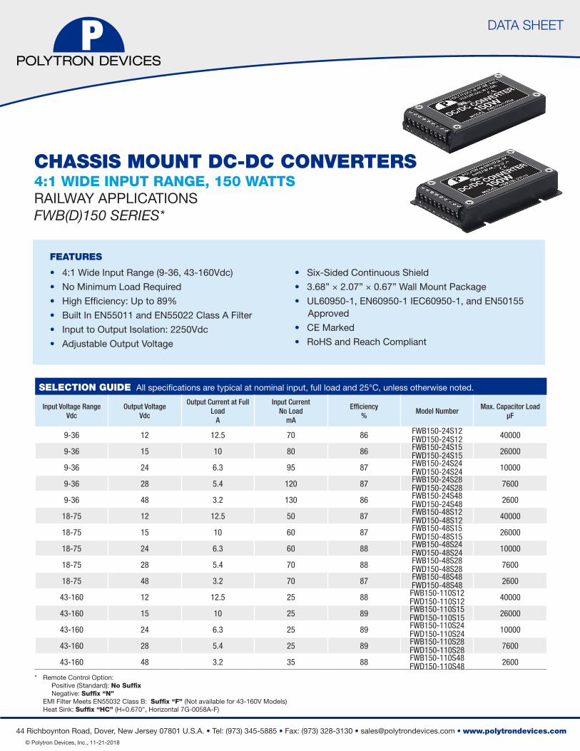
DATA SHEET
44 Richboynton Road, Dover, New Jersey 07801 U.S.A. • Tel: (973) 345-5885 • Fax: (973) 328-3130 • [email protected] • www.polytrondevices.com © Polytron Devices, Inc., 11-21-2018
DATA SHEET
FEATURES
• 4:1 Wide Input Range (9-36, 43-160Vdc)
• No Minimum Load Required
• High Efficiency: Up to 89%
• Built In EN55011 and EN55022 Class A Filter
• Input to Output Isolation: 2250Vdc
• Adjustable Output Voltage
• Six-Sided Continuous Shield
• 3.68” × 2.07” × 0.67” Wall Mount Package
• UL60950-1, EN60950-1 IEC60950-1, and EN50155 Approved
• CE Marked
• RoHS and Reach Compliant
SELECTION GUIDE All specifications are typical at nominal input, full load and 25°C, unless otherwise noted.
Input Voltage RangeVdc
Output VoltageVdc
Output Current at Full Load
A
Input Current No Load
mA
Efficiency%
Model NumberMax. Capacitor Load
μF
9-36 12 12.5 70 86 FWB150-24S12FWD150-24S12 40000
9-36 15 10 80 86 FWB150-24S15FWD150-24S15 26000
9-36 24 6.3 95 87 FWB150-24S24FWD150-24S24 10000
9-36 28 5.4 120 87 FWB150-24S28FWD150-24S28 7600
9-36 48 3.2 130 86 FWB150-24S48FWD150-24S48 2600
18-75 12 12.5 50 87 FWB150-48S12FWD150-48S12 40000
18-75 15 10 60 87 FWB150-48S15FWD150-48S15 26000
18-75 24 6.3 60 88 FWB150-48S24FWD150-48S24 10000
18-75 28 5.4 70 88 FWB150-48S28FWD150-48S28 7600
18-75 48 3.2 70 87 FWB150-48S48FWD150-48S48 2600
43-160 12 12.5 25 88 FWB150-110S12FWD150-110S12 40000
43-160 15 10 25 89 FWB150-110S15FWD150-110S15 26000
43-160 24 6.3 25 89 FWB150-110S24FWD150-110S24 10000
43-160 28 5.4 25 89 FWB150-110S28FWD150-110S28 7600
43-160 48 3.2 35 88 FWB150-110S48FWD150-110S48 2600
Remote Control Option:Positive (Standard): No SuffixNegative: Suffix “N”
EMI Filter Meets EN55032 Class B: Suffix “F” (Not available for 43-160V Models)Heat Sink: Suffix “HC” (H=0.670”, Horizontal 7G-0058A-F)
CHASSIS MOUNT DC-DC CONVERTERS4:1 WIDE INPUT RANGE, 150 WATTS RAILWAY APPLICATIONSFWB(D)150 SERIES*
*

DATA SHEET
44 Richboynton Road, Dover, New Jersey 07801 U.S.A. • Tel: (973) 345-5885 • Fax: (973) 328-3130 • [email protected] • www.polytrondevices.com © Polytron Devices, Inc., 11-21-2018
Input Specifications
Operating input voltage range, Vdc
9 Min., 24 Typ., 36 Max. 24V(nom)
18 Min., 48 Typ., 75 Max. 48V(nom)
43 Min., 110 Typ., 160 Max.
110V(nom)
Start up voltage, Vdc
9 Max. 24V(nom)
18 Max. 48V(nom)
43 Max. 110V(nom)
Shutdown voltage
7.9 Min., 8.5 Max. 24V(nom)
15.6 Min., 16.8 Max. 48V(nom)
33 Min., 36 Max. 110V(nom)
Start up time, ms
35 Typ. Constant resistive load, Power up
35 Typ. Remote ON/OFF
Input surge voltage 1,000mS Max., Vdc
50 Max. 24V(nom)
100 Max. 48V(nom)
185 Max. 110V(nom)
Input filter Pi type
Remote ON/OFF
Referenced to -Vin pin
Open or 3 - 12VdcPositive logic (standard) DC-DC ON
Short or 0 - 1.2VdcPositive logic (standard) DC-DC OFF
Short or 0 - 1.2Vdc Negative logic (option) DC-DC ON
Open or 3 - 12Vdc Negative logic (option) DC-DC OFF
-0.5 Min., 1 Max., mA Input current of Ctrl pin
3.5mA Typ. Remote off input current
Output Specifications
Voltage accuracy, % -1 Min., +1 Max.
Line regulation, % -0.2 Min., +0.2 Max. Low Line to High Line at Full Load
Load regulation, % -0.4 Min., +0.4 Max. No Load to Full Load
Voltage and adjustability, % +20 Max.
Use a resistor aacross on the Trim1 and Trim2 to adjust the output voltage.
Ripple and Noise, mVp-p
Measured by 20MHz bandwidth
100 Typ. With a 12Vout, 15Vout
200 Typ. With a 24Vout, 28Vout
350 Typ. With a 48Vout
Temperature coefficient, %/ºC
-0.02 Min., +0.02 Max.
Transient response recovery time, μs 200 Typ. 25% load step change
Over voltage protection, % 125 Min., 140 Max. % of Vout(nom); Hiccup mode
Over load protection, % 105 Min., 120 Max. % of lout rated; CC mode
Short circuit protection Continuous, automatics recovery
FWB(D)150 SERIES
General Specifications
Isolation voltage, Vdc1 minute Input to Output 2250 Min.1 minute Input (Output) to Case 1600 Min.
Isolation resistance, GΩ 500Vdc 1 Min.Isolation capacitance, pF 3500 Max.
Switching frequency, kHz
24Vdc Input 48Vout 248 Min. 275 Typ. 303 Max.Others 270 Min. 300 Typ. 330 Max.
48Vdc Input 48Vout 248 Min. 275 Typ. 303 Max.Others 270 Min. 300 Typ. 330 Max.
110Vdc Input All 203 Min. 225 Typ. 248 Max.
Environmental Specifications
Operating case temperature, ºC -40 Min. +110 Max.
Over temperature protection, ºC +110 Typ.
Storage temperature range, ºC -55 Min. +125 Max.
Thermal impedance(1), ºC/W
Vertical direction by natural convection (20LFM)
Only mount on the iron base-plate +2.55 Typ.
Mount on the iron base-plate and top side with 7G-0058A Heat-sink +2.0 Typ.
Thermal shock MIL-STD-810F
Shock EN61373, MIL-STD-810F
Vibration EN61373, MIL-STD-810F
Relative humidity 5% to 95% RH

DATA SHEET
44 Richboynton Road, Dover, New Jersey 07801 U.S.A. • Tel: (973) 345-5885 • Fax: (973) 328-3130 • [email protected] • www.polytrondevices.com © Polytron Devices, Inc., 11-21-2018
Note:
1. (1)The iron base-plate dimension is 19” * 3.5” * 0.063” (The height is EIA standard 2U). (2)The heat-sink is optional and P/N is 7G-0058A-F.
2. The standard modules meet EMI Class A without external components.
3. An external input filter capacitor is required if the module has to meet EN61000-4-4, EN61000-4-5. The filter capacitor Polytron suggest: FWB(D)150-24SXX : Nippon chemi-con KY series, 470μF/50V. FWB(D)150-24SXX :: Nippon chemi-con KY series, 220μF/100V. FWB(D)150-110SXX : Nippon chemi-con KXJ series, 150μF/200V.
CAUTION: This power module is not internally fused; an input line fuse must always be used. If the load was having sourcing capability (Ex: Battery or Super Capacitor), an output line fuse must always be used.
FWB(D)150 SERIES
Characteristic Curve
FWB(D)150-48S24 Derating Curve (Note 1) FWB(D)150-48S24 Derating Curve (Note 1)With Heat-sink
FWB(D)150-48S24 Efficiency vs. Input Voltage FWB(D)150-48S24 Efficiency vs. Output Load
AMBIENT TEMPERATURE(ºC) AMBIENT TEMPERATURE(ºC)
AMBIENT TEMPERATURE(ºC) AMBIENT TEMPERATURE(ºC)
Physical Specifications
Design meet safety standard
UL60950-1, EN60950-1, IEC60950-1, EN50155, CE
Case material Aluminum
Base material Aluminum
Potting material Silicon (UL94-V0)
Weight225g (7.94oz.), FWB150
220g (7.76oz.), FWD150
MTBF4.954×105 hrs, MIL-HDBK-217F, Full load
Dimensions 3.68” × 2.07” × 0.67”
EMC Specifications
Specifications Conditions Level
EMI(2)
EN55011, EN55022, EN50121-3-2
DC-DC Module, Class A
ESD EN61000-4-2 Air ±8kV and Contact ±6kV Perf. Criteria A
Radiated immunity EN61000-4-3 10V/m Perf. Criteria A
Fast transient (3) EN61000-4-4 ±2kV Perf. Criteria A
Surge(3) EN61000-4-5 EN55024 ±1kV, EN50155 ±2kV Perf. Criteria A
Conducted immunity EN61000-4-6 10 Vr.m.s Perf. Criteria A

DATA SHEET
44 Richboynton Road, Dover, New Jersey 07801 U.S.A. • Tel: (973) 345-5885 • Fax: (973) 328-3130 • [email protected] • www.polytrondevices.com © Polytron Devices, Inc., 11-21-2018
Characteristic Curve (Continued)
FWB(D)150-XXS12Vout vs. lout
FWB(D)150-XXS15Vout vs. lout
FWB(D)150-XXS24Vout vs. lout
FWB(D)150-XXS28Vout vs. lout
FWB(D)150-XXS48Vout vs. lout
FWB(D)150 SERIES
Note:
1. This series can operated in CC and CV mode, so it can operate at up to 200 watts. The Vout adjustability is 20% of output voltage and the output current can operate 1.1 times and above when in CC mode. Example 1: Vout=15V, full load=10A and normal output =150W. If trim up 20% and in CC mode, the total power will be 198W [(15V*1.2)*(10A*1.1)]. Example 2: Vout=48V and full load=3.2A, but 3.5A when in CC mode. The total power will be up to 201.6 watt. (48V*1.2)*3.5A=201.6W.
2. CV Region: In normal operation. The output current in datasheet Condition: Resistance Load > Vout / Iout (CC Point)
3. CC Region: If the output load current are over rating. The output current will keep in a constant value. And output voltagewill fall. Condition: Resistance Load < Vout / Iout (CC Point)
4. Hiccup Protection: If the output resistance is become short. It will operate in hiccup protection. Condition: FWB(D)150-XXS12, FWB(D)150-XXS15: Vout < 4.3V (typ.) to Output Short. FWB(D)150-XXS24, FWB(D)150-XXS28: Vout < 8.0V (typ.) to Output Short. FWB(D)150-XXS48: Vout < 13V(typ.) to Output Short.

DATA SHEET
44 Richboynton Road, Dover, New Jersey 07801 U.S.A. • Tel: (973) 345-5885 • Fax: (973) 328-3130 • [email protected] • www.polytrondevices.com © Polytron Devices, Inc., 11-21-2018
Mechanical Drawing
FWB150 Dimensions PIN CONNECTION
PIN DEFINE RECOMMEND MATCHING WIRE (AWG)
1 +Vin 14-16
2 +Vin 14-16
3 -Vin 14-16
4 -Vin 14-16
5 Ctrl 14-24
6 +Vout 14-16
7 -Vout 14-16
8 Trim 1 14-24
9 Trim 2 14-24
EXTERNAL OUTPUT TRIMMING
Output can be externally trimmed by using the method shown below.
FWD150 Dimensions
FWB(D)150 SERIES
1. All dimensions in inch (mm)2. Tolerance: x.xx±0.02(x.x±0.5)
x.xxx±0.01 (x.xx±0.25)3. Pole pitch tolerance ±0.01 (0.25)4. Screw locked torque: MAX 5.0kgf-cm(0.49N-m)5. Terminal screw locked torque: MAX 2.5kgf-cm(0.25N-m)
TOP VIEW
2.56(65.0)
2.32(59.0)
1.673(42.50)
1.78(45.2)
2.07(52.5)
0.197(5.00)
Terminal screw
98764 5321
0.67
(17.
0)
0.05
(1.2
)
0.47
(12.
0)
2.20
5(56
.00)
3.18
9(81
.00)
0.83
(21.
0)
0.20
(5.0
)
3.86
(98.
0)S
crew
4-M
3X0.
5
Scr
ew 4
-M3X
0.5
2.07(52.5)
98764 5321
TOP VIEW
Screw 4-M3X0.51.673(42.50)
Terminal screw
0.197(5.00)
0.67
(17.
0)3.
86(9
8.0)
3.18
9(81
.00)
0.47
(12.
0)

DATA SHEET
44 Richboynton Road, Dover, New Jersey 07801 U.S.A. • Tel: (973) 345-5885 • Fax: (973) 328-3130 • [email protected] • www.polytrondevices.com © Polytron Devices, Inc., 11-21-2018
Heat-Sink Type Options
1. All dimensions in inch (mm)
2. Tolerance :x.xx±0.02 (xx.x±0.5)
x.xxx±0.01 (x.xx±0.25)
Mechanical Drawing (Continued)
FWB150-24SXX-F Dimensions FWB150-48SXX-F Dimensions
7G-0058A-F, Suffix:-HC
98764 5321
TOP VIEW
2.323(59.00)
1.673(42.50)
4-M3X0.5 Note 5Screw for Heatsink
1.673(42.50)
2.56(65.0)
2.1(52.5)
Pin Pitch=5.0mm
6.32
(160
.5)
2.10
(52.
9)
1.85
2(47
.05)
3.18
9(81
.00)
0.20
(5.0
)
0.16
(4.0
) 2.46
0(62
.50)
2.20
5(56
.00)
0.83
(21.
0)
6-M
3X0.
5 N
ote
5H
ole
for
Set
up
0.06
2(1.
60)
0.74
(18.
7)
1. All dimensions in inch (mm)2. Tolerance: x.xx±0.02(x.x±0.5)
x.xxx±0.01 (x.xx±0.25)3. Pole pitch tolerance ±0.01 (0.25)4. Screw locked torque: MAX 5.0kgf-cm(0.49N-m)5. Terminal screw locked torque: MAX 2.5kgf-cm(0.25N-m)
PIN DEFINE RECOMMEND MATCHING WIRE (AWG)
1 +Vin 14-16
2 +Vin 14-16
3 -Vin 14-16
4 -Vin 14-16
5 Ctrl 14-24
6 +Vout 14-16
7 -Vout 14-16
8 Trim 1 14-24
9 Trim 2 14-24
PIN CONNECTION


![FAMILY WELLBEING [FWB] NEWSLETTER](https://img.pdfslide.us/doc/110x75/618e6b4e6b8bee219f4eb123/family-wellbeing-fwb-newsletter.jpg)