Embed Size (px)
Citation preview

1
4.1 General Background
Angles in surveying are measured withA transit / theodolite , or
Total station

2
4.2 Reference Directions for Vertical Angles
Vertical angles are referenced to:1. The horizon by up (+), or down (-)2. Zenith3. Nadir
Note:Zenith: is directly above the observerNadir : is directly below the observer
the three reference directions for vertical angles: horizontal, zenith, and nadir.
Figure 4.1

3
4.3 MeridiansA line on the mean surface of
the earth joining north and south poles is called meridian.
Note: Geographic meridians are
fixed, magnetic meridians vary with time and location.
Relationship between “true”meridian and grid meridians
Figure 4.2
latitude
longitude
4.4 Horizons Angles
Horizontal angles are usually measured with a theodolite or total stations whose precision can range from 1 second to 20 seconds
For all closed polygons of n sides, the sum of the interior angles will be (n-2)x 180o
For all closed polygons of n sides, the sum of the exterior angles equal to
(n+2)180ْ
4
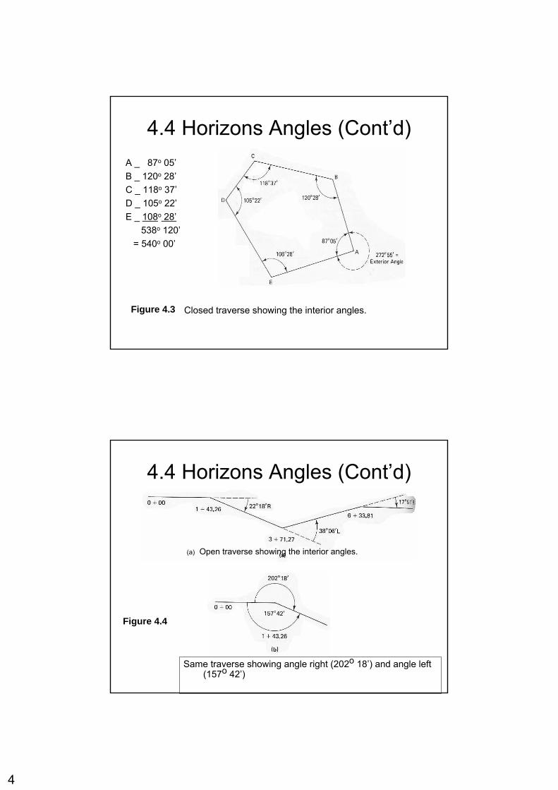
4.4 Horizons Angles (Cont’d)
Closed traverse showing the interior angles.Figure 4.3
A _ 87o 05’B _ 120o 28’C _ 118o 37’D _ 105o 22’E _ 108o 28’
538o 120’= 540o 00’
4.4 Horizons Angles (Cont’d)
Same traverse showing angle right (202o 18’) and angle left (157o 42’)
Figure 4.4
(a) Open traverse showing the interior angles.

5
4.5 Azimuths
An azimuths is direction of line as given by an angle measured clockwise (usually) from the north end of a meridian.Azimuths range is magnitude from 0o to 360o
4.5: Azimuths:
325ْ0-4202ْ0-3121ْ0-252ْ0-1
AzimuthLine

6
4.6 BearingsBearings is the direction of a line as given by the acute angle between the line and a meridian.
The bearing angle, is always accompanied by letters that locate the quadrant in which the line falls (NE, NW, SE, or SW).
4.6 Bearings (Cont’d)
N 10o 45’ W0 – 8S 27o 30’ W0 – 7S 24o 50’ E0 - 6 N 58o 20’ E0 - 5BearingsLine
Figure 4.6Bearings calculated from given data

7
N10ْ00’W0-4S28ْ00’W0-3S25ْ00’E0-2N58ْ00’E0-1BearingLine
4.7 Relationships Between Bearings and Azimuths
• To convert from azimuths to bearings by using this table:
bearing= 360ْ - azimuthNWFrom 270ْ to 360ْbearing= azimuth - 180ْSWFrom 180ْ to 270ْbearing= 180ْ - azimuthSEFrom 90ْ to 180ْbearing = azimuthNEFrom 0ْ to 90ْ
Numerical valuequadrant lettersquadrant

8
4.7 Relationships Between Bearings and Azimuths
• To convert from bearings to azimuths by using this relationships:
1. NE quadrant azimuth = bearing
2. SE quadrant azimuth = 180ْ– bearing
3. SW quadrant azimuth = 180 ْ+ bearing
4. NW quadrant azimuth = 360ْ– bearing
• Example: convert :
1. 200ْ58’ = S20ْ58’W
2. N2ْ21’W = 357ْ39’
4.8: Reverse Directions:
• It can be said that every line has two direction.
• Forward direction is direction that oriented in the direction of fieldwork or computation staging.
• Back direction is direction that oriented in the reverse of the direction fieldwork or computation staging.

9
4.8 Reverse Direction
In figure 4.8 , the line AB has a bearing of N 62o 30’ EBA has a bearing of S 62o 30’ W
To reverse bearing: reverse the direction
Figure 4.7Reverse Directions Figure 4.8
Reverse Bearings
S 62o 30’ WBA
N 62o 30’ EAB
BearingLine
S 62o 30’ WBA
N 62o 30’ EAB
BearingLine
S 60ْ00’ WBA
N 60ْ00’ EABBearingLine
• To reverse a bearing … Reverse the direction letters.
Example:
10
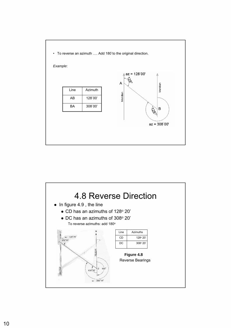
• To reverse an azimuth …. Add 180ْ to the original direction.
Example:
308ْ00’BA
128ْ00’AB
AzimuthLine
4.8 Reverse DirectionIn figure 4.9 , the line
CD has an azimuths of 128o 20’DC has an azimuths of 308o 20’
To reverse azimuths: add 180o
Figure 4.8Reverse Bearings
308o 20’DC
128o 20’CD
AzimuthsLine

11
4.8 Counterclockwise Direction (1)
StartGiven

12
4.8 Counterclockwise Direction (2)
4.8 Counterclockwise Direction (3)

13
4.8 Counterclockwise Direction (4)
4.8 Counterclockwise Direction (5)FinishCheck

14
StartGiven
FinishCheck
4.8 Clockwise Direction (1)
StartGiven

15
4.8 Clockwise Direction (2)
4.8 Clockwise Direction (3)

16
4.8 Clockwise Direction (4)
4.8 Clockwise Direction (5)
FinishCheck

17
StartGiven
FinishCheck
4.9 Azimuths Computation
Counterclockwise direction: add the interior angle to the back azimuth of the previous course
N 30o 00’ W330o 00’ABN 62o 55’ E62o 55’EAS 45o 33’ E134o 27’DE
S 29o 05’ W209o 05’CDN 89o 32’ W270o 28’BC
BearingAzimuths Course

18
4.9 Azimuths Computation
Clockwise direction: subtract the interior angle from the back azimuth of the previous course
S 30o 00’ E150o 00’BAS 89o 32’ E90o 28’CBN 29o 05’ E29o 25’DC
N 45o 33’ W314o 27’EDS 62o 55’ W242o 55’AE
BearingAzimuths Course
4.10 Bearing ComputationComputation can proceed in a Clockwise or counterclockwise
Figure 4.11Sketch for Bearings Computations

19
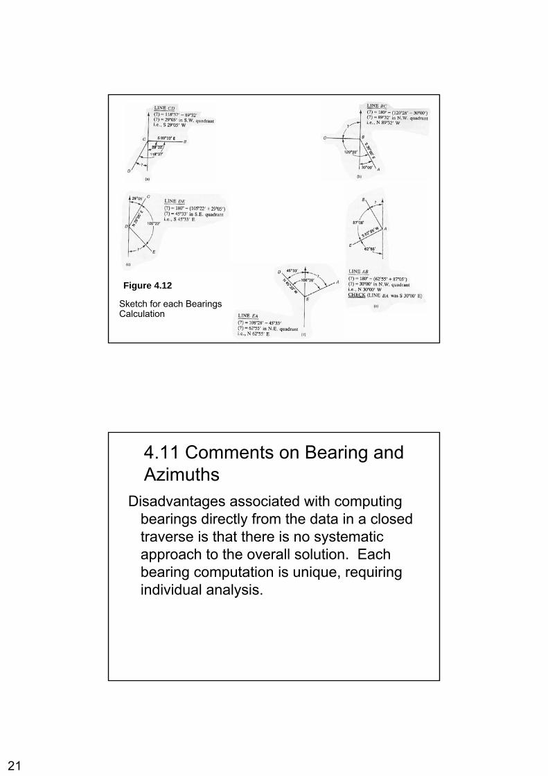
4.10: Bearing Computation:Line BC:
(?)= 180 – (120ْ28’- 30ْ )
(?)= 89ْ32’ in N.W quad.
i.e., N 89ْ32’ W
Line CD:
(?)= 118ْ37’- 89ْ32’
(?)= 29ْ05’ in S.W quad.
i.e., S 29ْ05’ W
Line DE:
(?)= 180ْ– (105ْ22’+29ْ05’)
(?)= 45ْ33’ in S.E. quad.
i.e., S 45ْ33’ E
Line EA:
(?)= 108ْ28’- 45ْ33’
(?)= 62ْ55’ in N.E. quad.
i.e., N 62ْ55’ E

20
Line AB:
(?)= 180ْ– (62ْ55’+ 87ْ05’)
(?)= 30ْ00’ in N.W. quad.
i.e., N 30ْ00’ W
CHECK (Line AB was S 30ْ00’ E )
4.11 Comments on Bearing and Azimuths
Advantage of computing bearings directly from the given data in a closed traverse, is that the final computation provides a check on all the problem, ensuring the correctness of all the computed bearings
21
Figure 4.12
Sketch for each Bearings Calculation
4.11 Comments on Bearing and Azimuths
Disadvantages associated with computing bearings directly from the data in a closed traverse is that there is no systematic approach to the overall solution. Each bearing computation is unique, requiring individual analysis.

22
4.11 Comments on Bearing and Azimuths
The computation of azimuths involves a highly systematic routine: add (subtract) the interior angle from the back azimuths of the previous course.
Figure 4.13
Summery of Results from clockwise and counterclockwise approaches

23
4.12: Magnetic Direction:
• Magnetic Direction is the horizontal angle between magnetic north and geographic north.
• Isogonic chart is line joining points of the earth surface having equal magnetic declination.
Geographic Bearing of survey Line = 18ْ36’+ 10ْ30’


![1. [Group] Slide01 2. background - Friendship Church · 1. [Group] Slide01 2. background 3. background 4. background!!"!!";&$ 5. Minnesota Miracle Reactio… 6. background!Make a](https://img.pdfslide.us/doc/110x75/5f29a750c10e4376fe0a71c0/1-group-slide01-2-background-friendship-church-1-group-slide01-2-background.jpg)