Embed Size (px)
Citation preview
ACCU-GOLD QUICK START MANUAL
Nowincludessupport
forthelightsensor
(AGLS)andAccu‐Gold+
digitizersandsensors
(AGDM+,AGMS‐DM+)
Accu-Gold QUICK START MANUAL
1
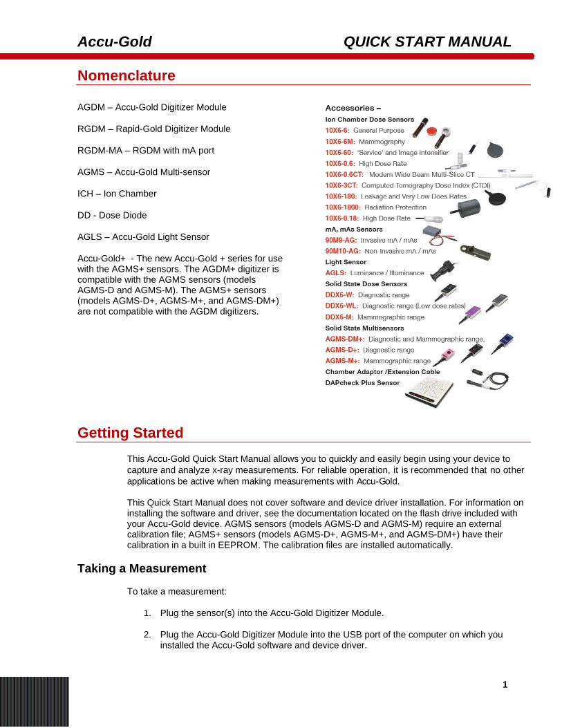
Nomenclature
AGDM – Accu-Gold Digitizer Module
RGDM – Rapid-Gold Digitizer Module
RGDM-MA – RGDM with mA port
AGMS – Accu-Gold Multi-sensor
ICH – Ion Chamber
DD - Dose Diode
AGLS – Accu-Gold Light Sensor
Accu-Gold+ - The new Accu-Gold + series for use with the AGMS+ sensors. The AGDM+ digitizer is compatible with the AGMS sensors (models AGMS-D and AGMS-M). The AGMS+ sensors (models AGMS-D+, AGMS-M+, and AGMS-DM+) are not compatible with the AGDM digitizers.
Getting Started This Accu-Gold Quick Start Manual allows you to quickly and easily begin using your device to capture and analyze x-ray measurements. For reliable operation, it is recommended that no other applications be active when making measurements with Accu-Gold.
This Quick Start Manual does not cover software and device driver installation. For information on installing the software and driver, see the documentation located on the flash drive included with your Accu-Gold device. AGMS sensors (models AGMS-D and AGMS-M) require an external calibration file; AGMS+ sensors (models AGMS-D+, AGMS-M+, and AGMS-DM+) have their calibration in a built in EEPROM. The calibration files are installed automatically.
Taking a Measurement
To take a measurement:
1. Plug the sensor(s) into the Accu-Gold Digitizer Module.
2. Plug the Accu-Gold Digitizer Module into the USB port of the computer on which you installed the Accu-Gold software and device driver.
Accu-Gold QUICK START MANUAL
1
3. Place the sensor in the path of the X-ray beam.
4. Launch the Accu-Gold software. The Accu-Gold screen appears and indicates that the sensor is offline.
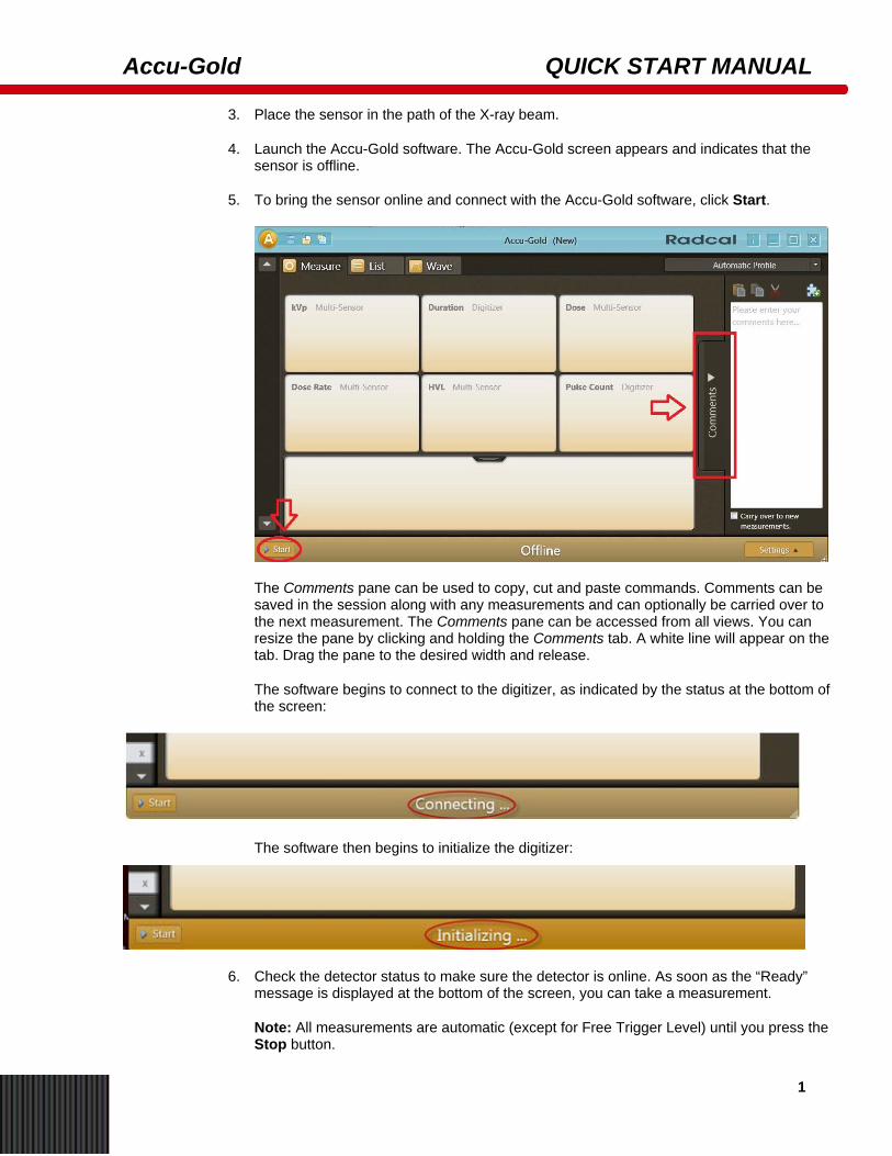
5. To bring the sensor online and connect with the Accu-Gold software, click Start.
The Comments pane can be used to copy, cut and paste commands. Comments can be saved in the session along with any measurements and can optionally be carried over to the next measurement. The Comments pane can be accessed from all views. You can resize the pane by clicking and holding the Comments tab. A white line will appear on the tab. Drag the pane to the desired width and release.
The software begins to connect to the digitizer, as indicated by the status at the bottom of the screen:
The software then begins to initialize the digitizer:
6. Check the detector status to make sure the detector is online. As soon as the “Ready” message is displayed at the bottom of the screen, you can take a measurement.
Note: All measurements are automatic (except for Free Trigger Level) until you press the Stop button.
Accu-Gold QUICK START GUIDE
2
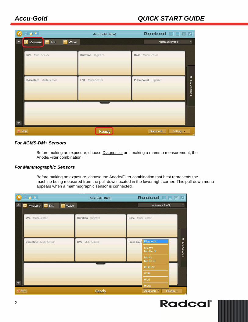
For AGMS-DM+ Sensors
Before making an exposure, choose Diagnostic, or if making a mammo measurement, the Anode/Filter combination.
For Mammographic Sensors
Before making an exposure, choose the Anode/Filter combination that best represents the machine being measured from the pull-down located in the lower right corner. This pull-down menu appears when a mammographic sensor is connected.
Accu-Gold QUICK START MANUAL
3
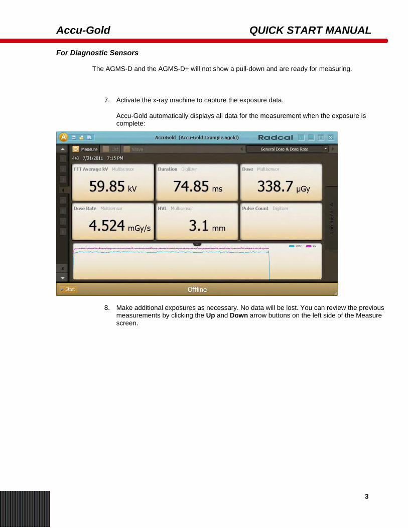
For Diagnostic Sensors
The AGMS-D and the AGMS-D+ will not show a pull-down and are ready for measuring.
7. Activate the x-ray machine to capture the exposure data.
Accu-Gold automatically displays all data for the measurement when the exposure is complete:
8. Make additional exposures as necessary. No data will be lost. You can review the previous measurements by clicking the Up and Down arrow buttons on the left side of the Measure screen.
Accu-Gold QUICK START GUIDE
4
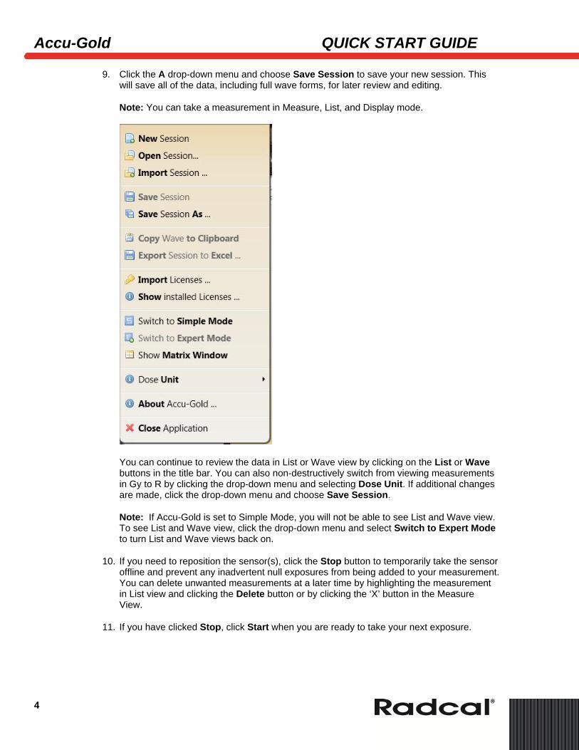
9. Click the A drop-down menu and choose Save Session to save your new session. This will save all of the data, including full wave forms, for later review and editing.
Note: You can take a measurement in Measure, List, and Display mode.
You can continue to review the data in List or Wave view by clicking on the List or Wave buttons in the title bar. You can also non-destructively switch from viewing measurements in Gy to R by clicking the drop-down menu and selecting Dose Unit. If additional changes are made, click the drop-down menu and choose Save Session.
Note: If Accu-Gold is set to Simple Mode, you will not be able to see List and Wave view. To see List and Wave view, click the drop-down menu and select Switch to Expert Mode to turn List and Wave views back on.
10. If you need to reposition the sensor(s), click the Stop button to temporarily take the sensor offline and prevent any inadvertent null exposures from being added to your measurement. You can delete unwanted measurements at a later time by highlighting the measurement in List view and clicking the Delete button or by clicking the ‘X’ button in the Measure View.
11. If you have clicked Stop, click Start when you are ready to take your next exposure.
Accu-Gold QUICK START MANUAL
5
Taking a Measurement with Multiple Sensors Connected
Note: If you click Start and the AG software cannot locate a matching license file, it will provide a dialog box asking you to locate it. The calibration file is found on the flash drive attached to the cable. All AGMS+ sensors have calibration built in.
The Accu-Gold Digitizer Module (AGDM/AGDM+) allows you to connect up to five sensors and take simultaneous measurements. The Rapid-Gold Digitizer Module (RGDM/RGDM+) has only the multi-sensor port. The Rapid-Gold Digitizer Module (RGDM-MA/RGDM+MA) has the multi-sensor and mA port. The five sensor ports are:
• AGMS – Accu-Gold multi-sensor (AGDM/RGDM).
• ICH – Ion Chamber (AGDM only).
• DD – – Dose Diode (AGDM only).
• mA – l 90M9 and 90M10 mA/mAs sensors (AGDM/RGDM-MA).
• AUX – Auxiliary connector for the light sensor, DAP-Check and future sensors (AGDM only).
To take a measurement using more than one sensor:
1. Click Stop in the Accu-Gold software Measurement view to stop the software from taking measurements.
2. Plug any additional sensors into the available ports.
3. Position the new sensors into the X-ray beam.
4. Press Start to bring the sensor on-line. Make an exposure.
Accu-Gold QUICK START GUIDE
6
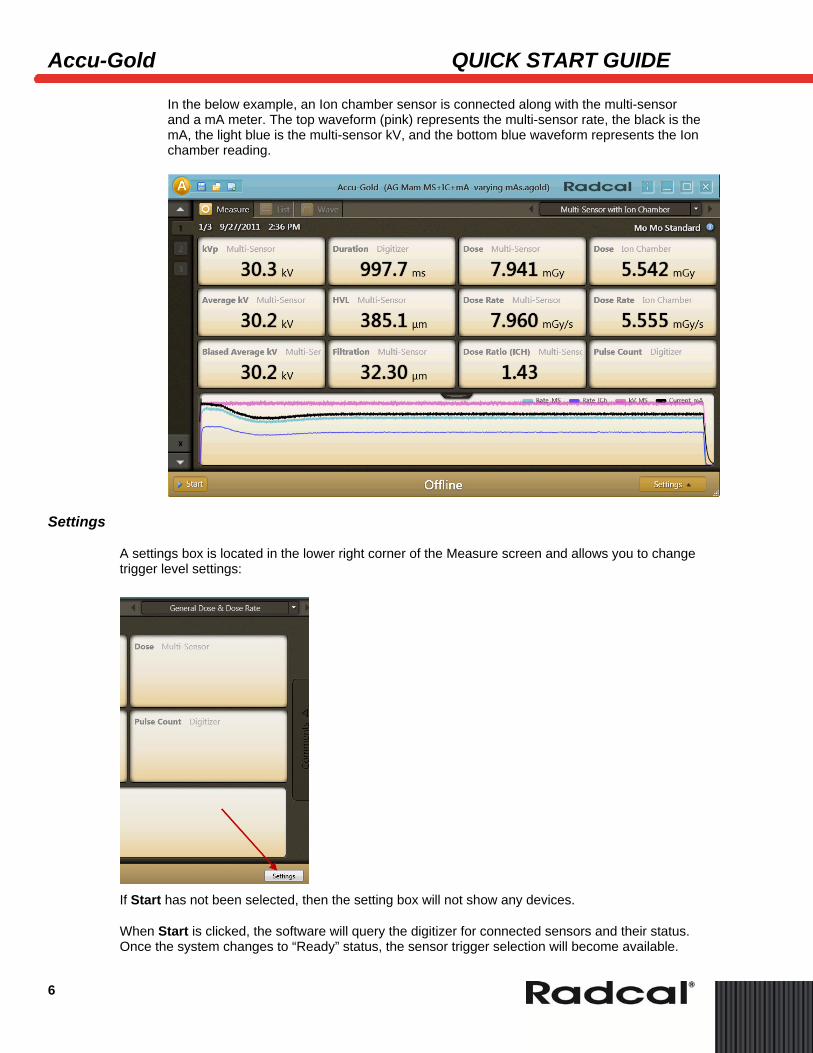
In the below example, an Ion chamber sensor is connected along with the multi-sensor and a mA meter. The top waveform (pink) represents the multi-sensor rate, the black is the mA, the light blue is the multi-sensor kV, and the bottom blue waveform represents the Ion chamber reading.
Settings
A settings box is located in the lower right corner of the Measure screen and allows you to change trigger level settings:
If Start has not been selected, then the setting box will not show any devices.
When Start is clicked, the software will query the digitizer for connected sensors and their status. Once the system changes to “Ready” status, the sensor trigger selection will become available.
Accu-Gold QUICK START MANUAL
7
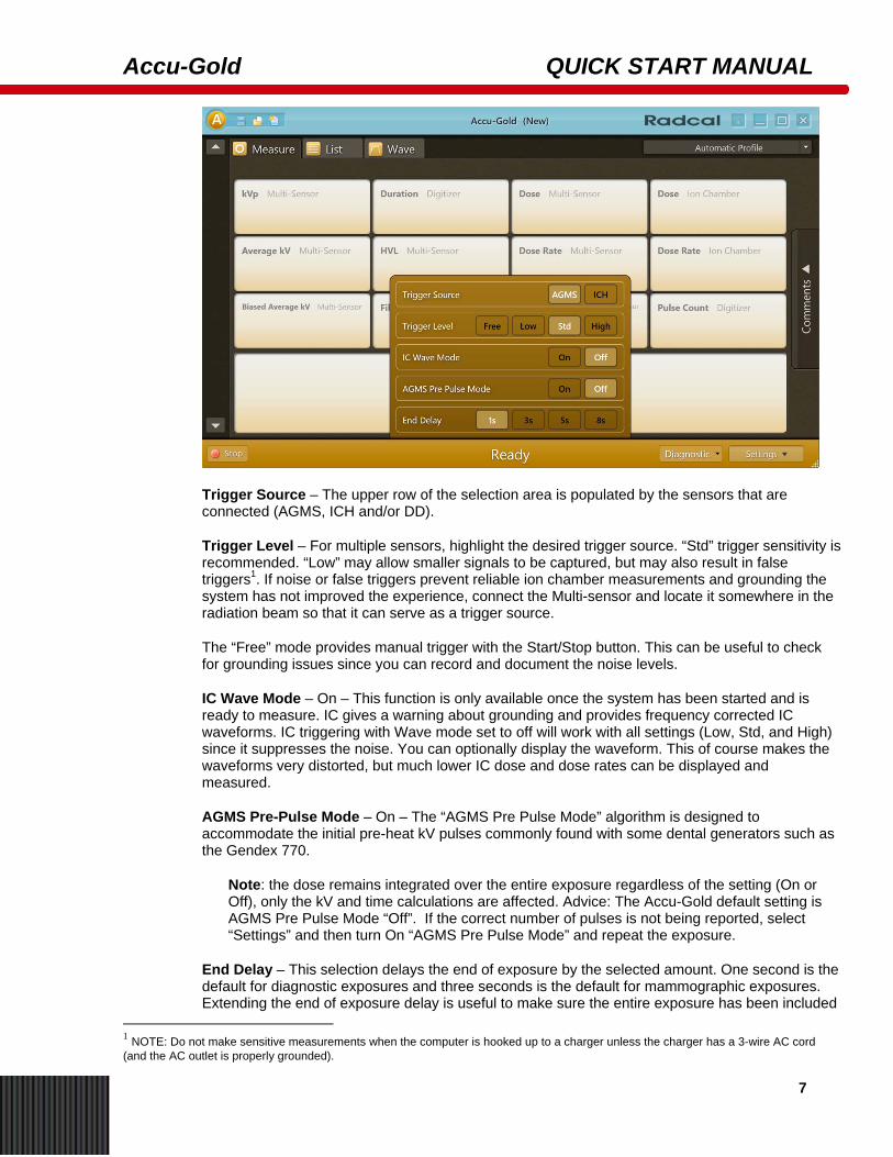
Trigger Source – The upper row of the selection area is populated by the sensors that are connected (AGMS, ICH and/or DD).
Trigger Level – For multiple sensors, highlight the desired trigger source. “Std” trigger sensitivity is recommended. “Low” may allow smaller signals to be captured, but may also result in false triggers1. If noise or false triggers prevent reliable ion chamber measurements and grounding the system has not improved the experience, connect the Multi-sensor and locate it somewhere in the radiation beam so that it can serve as a trigger source.
The “Free” mode provides manual trigger with the Start/Stop button. This can be useful to check for grounding issues since you can record and document the noise levels.
IC Wave Mode – On – This function is only available once the system has been started and is ready to measure. IC gives a warning about grounding and provides frequency corrected IC waveforms. IC triggering with Wave mode set to off will work with all settings (Low, Std, and High) since it suppresses the noise. You can optionally display the waveform. This of course makes the waveforms very distorted, but much lower IC dose and dose rates can be displayed and measured.
AGMS Pre-Pulse Mode – On – The “AGMS Pre Pulse Mode” algorithm is designed to accommodate the initial pre-heat kV pulses commonly found with some dental generators such as the Gendex 770.
Note: the dose remains integrated over the entire exposure regardless of the setting (On or Off), only the kV and time calculations are affected. Advice: The Accu-Gold default setting is AGMS Pre Pulse Mode “Off”. If the correct number of pulses is not being reported, select “Settings” and then turn On “AGMS Pre Pulse Mode” and repeat the exposure.
End Delay – This selection delays the end of exposure by the selected amount. One second is the default for diagnostic exposures and three seconds is the default for mammographic exposures. Extending the end of exposure delay is useful to make sure the entire exposure has been included
1 NOTE: Do not make sensitive measurements when the computer is hooked up to a charger unless the charger has a 3-wire AC cord (and the AC outlet is properly grounded).
Accu-Gold QUICK START GUIDE
8
in the measurement and is particularly useful for exposures with large gaps such as digital mammography or combined mode tomography.
Selecting a Display Profile
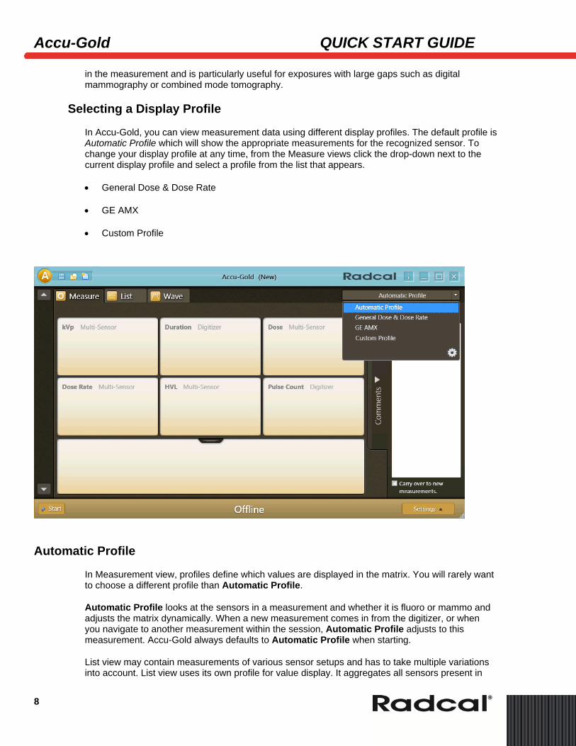
In Accu-Gold, you can view measurement data using different display profiles. The default profile is Automatic Profile which will show the appropriate measurements for the recognized sensor. To change your display profile at any time, from the Measure views click the drop-down next to the current display profile and select a profile from the list that appears.
• General Dose & Dose Rate
• GE AMX
• Custom Profile
Automatic Profile
In Measurement view, profiles define which values are displayed in the matrix. You will rarely want to choose a different profile than Automatic Profile.
Automatic Profile looks at the sensors in a measurement and whether it is fluoro or mammo and adjusts the matrix dynamically. When a new measurement comes in from the digitizer, or when you navigate to another measurement within the session, Automatic Profile adjusts to this measurement. Accu-Gold always defaults to Automatic Profile when starting.
List view may contain measurements of various sensor setups and has to take multiple variations into account. List view uses its own profile for value display. It aggregates all sensors present in
Accu-Gold QUICK START MANUAL
9
the session and selects a profile that contains all of them. The profile choice of Measurement view does not influence List view or Wave view. The profile of List view is used when exporting to a new file.
Custom Profile
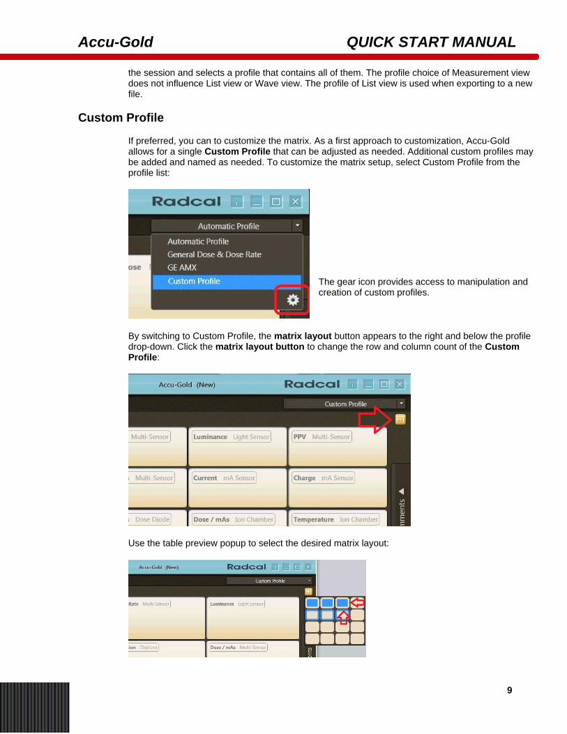
If preferred, you can to customize the matrix. As a first approach to customization, Accu-Gold allows for a single Custom Profile that can be adjusted as needed. Additional custom profiles may be added and named as needed. To customize the matrix setup, select Custom Profile from the profile list:
The gear icon provides access to manipulation and creation of custom profiles.
By switching to Custom Profile, the matrix layout button appears to the right and below the profile drop-down. Click the matrix layout button to change the row and column count of the Custom Profile:
Use the table preview popup to select the desired matrix layout:
Accu-Gold QUICK START GUIDE
10
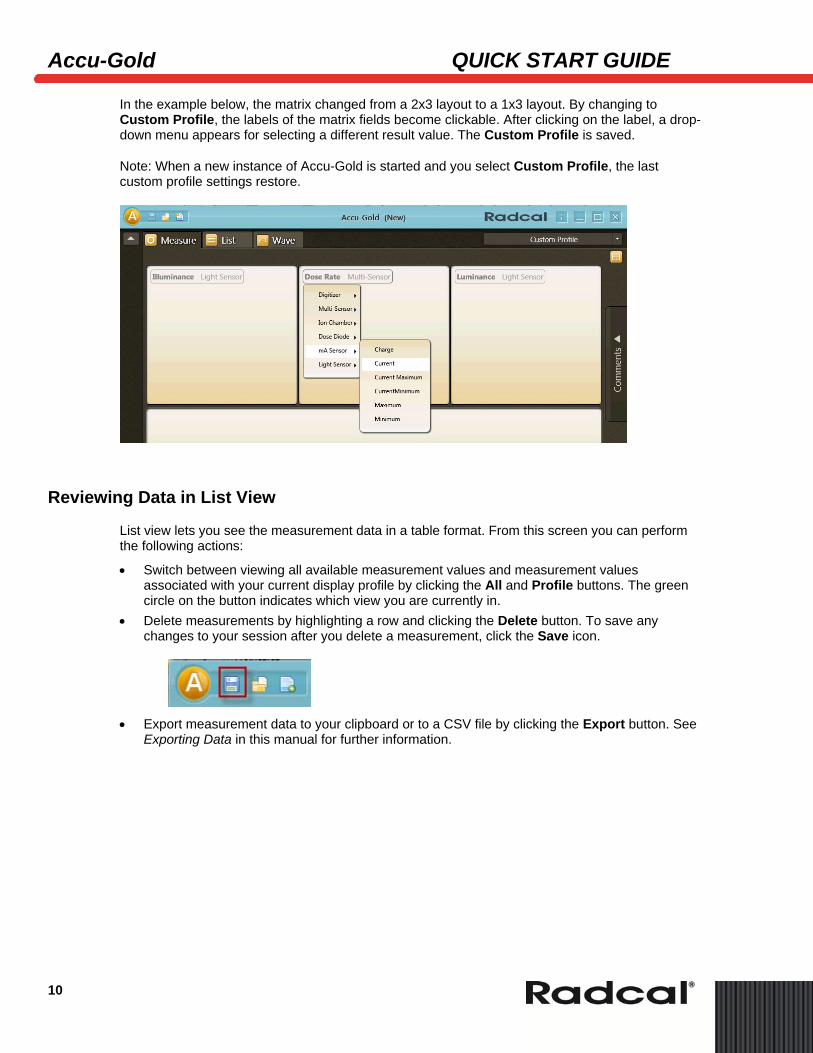
In the example below, the matrix changed from a 2x3 layout to a 1x3 layout. By changing to Custom Profile, the labels of the matrix fields become clickable. After clicking on the label, a drop-down menu appears for selecting a different result value. The Custom Profile is saved.
Note: When a new instance of Accu-Gold is started and you select Custom Profile, the last custom profile settings restore.
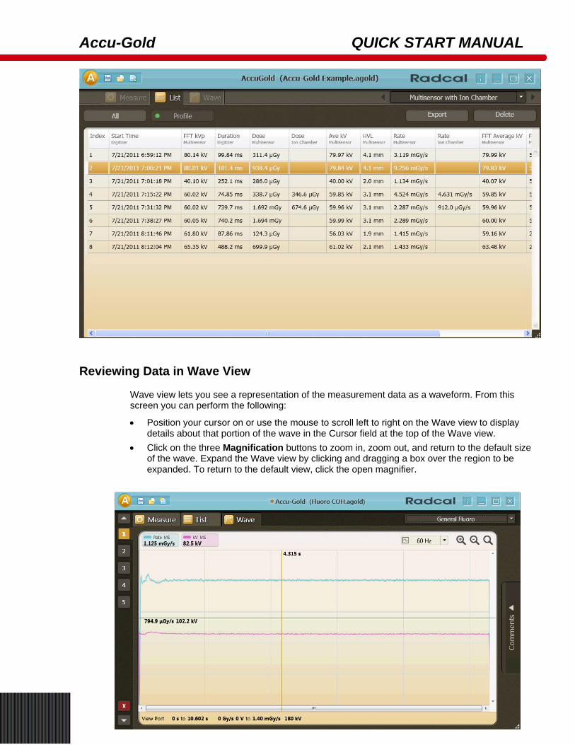
Reviewing Data in List View
List view lets you see the measurement data in a table format. From this screen you can perform the following actions:
• Switch between viewing all available measurement values and measurement values associated with your current display profile by clicking the All and Profile buttons. The green circle on the button indicates which view you are currently in.
• Delete measurements by highlighting a row and clicking the Delete button. To save any changes to your session after you delete a measurement, click the Save icon.
• Export measurement data to your clipboard or to a CSV file by clicking the Export button. See
Exporting Data in this manual for further information.
Accu-Gold QUICK START MANUAL
11
Reviewing Data in Wave View
Wave view lets you see a representation of the measurement data as a waveform. From this screen you can perform the following:
• Position your cursor on or use the mouse to scroll left to right on the Wave view to display details about that portion of the wave in the Cursor field at the top of the Wave view.
• Click on the three Magnification buttons to zoom in, zoom out, and return to the default size of the wave. Expand the Wave view by clicking and dragging a box over the region to be expanded. To return to the default view, click the open magnifier.
Ac
12
Exp
Expo
cu-Gold
porting a SYou can e
• E• E• A• A
Note: ExpWave to C
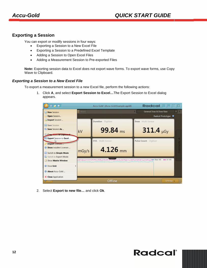
orting a SesTo export
1
2
d
Session export or modxporting a Sexporting a Se
Adding a SessAdding a Meas
porting sessioClipboard.
ssion to a Na measurem
. Click A, anappears.
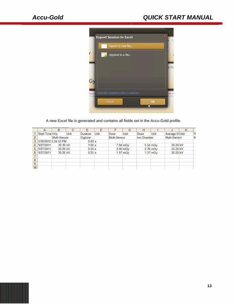
. Select Exp
dify sessions iession to a Neession to a Prsion to Open Esurement Ses
on data to Exc
New Excel Fment session t
nd select Exp
port to new f
in four ways: ew Excel Fileredefined ExcExcel Files ssion to Pre-e
cel does not e
File o a new Exce
port Session
file… and clic
Q
cel Template
exported Files
export wave f
el file, perform
to Excel…Th
ck Ok.
QUICK S
s
forms. To exp
m the following
he Export Ses
START G
port wave form
g actions:
ssion to Exce
GUIDE
ms, use Copy
el dialog
y
Acc
u-Gold
A new Exce
el file is generrated and conntains all fields
QUI
s set in the A
ICK STA
ccu-Gold pro
ART MAN
file.
NUAL
13

See the Accu-Gold User’s Manual for additional information. For questions or troubleshooting, contact Customer Support at (626) 357-7921 x 123 or email [email protected]
Radcal Corporation 426 West Duarte Road Monrovia, CA 91016-4591 USA USA (626) 357-7921 Fax USA (626) 357-8863 email sales@radcal.,com www.radcal.com 4094088 REV:E Printed: March 2014 Copyright© 2012,2013,2014