Embed Size (px)
Citation preview
PROGRAMMING MANUAL
Function/Arbitrary Waveform Generator
MODEL: 4050 Series (4052, 4053, 4054, 4055)


Table of Contents 1.1. About Commands & Queries ______________________________________ 1
1.2. Table of Commands & Queries ____________________________________ 3
1.3. IEEE 488.2 Common Command Introduction ______________________ 4
1.4. Output Command ________________________________________________ 6
1.5. Basic Wave Command ____________________________________________ 7
1.6. Modulate Wave Command ________________________________________ 8
1.7. Sweep Wave Command __________________________________________ 13
1.8. Burst Wave Command ___________________________________________ 15
1.9. Parameter Copy Command ______________________________________ 18
1.10. Arbitrary Wave Command _____________________________________ 18
1.11. Phase Command ______________________________________________ 20
1.12. Sync Command ________________________________________________ 20
1.13. Configuration Command _______________________________________ 21
1.14. Buzzer Command _____________________________________________ 21
1.15. Screen Save Command _________________________________________ 21
1.16. Clock Source Command ________________________________________ 22
1.17. Frequency Counter ____________________________________________ 22
1.18. Store list command ____________________________________________ 24
1.19. Get arbitrary wave data command ______________________________ 25
1.20. Virtual key command __________________________________________ 27
1.21. Index __________________________________________________________ 1


1
1.1. About Commands & Queries
This section lists and describes the remote control commands and queries recognized by the instrument. All commands and queries can be executed in either local or remote state. The description for each command or query, with syntax and other information, begins on a new page. The name (header) is given in both long and short form, and the subject is indicated as a command or query or both. Queries perform actions such as obtaining information, and are recognized by the question mark (?) following the header.
1.1.1. How they are listed
The descriptions are listed in alphabetical order according to their short form.
1.1.2. How they are described
In the descriptions themselves, a brief explanation of the function performed is given. This is followed by a presentation of the formal syntax, with the header given in Upper-and-Lower-Case characters and the short form derived from it in ALL UPPER-CASE characters. Where applicable, the syntax of the query is given with the format of its response.
1.1.3. When can they be used?
The commands and queries listed here can be used for 4050 Series arbitrary/function waveform generators.
1.1.4. Command Notation
The following notation is used in the commands: < > Angular brackets enclose words that are used
2
placeholders, of which there are two types: the header path and the data parameter of a command. := A colon followed by an equals sign separates a placeholder from the description of the type and range of values that may be used in a command instead of the placeholder. { } Braces enclose a list of choices, one of which one must be made. [ ] Square brackets enclose optional items. … An ellipsis indicates that the items both to its left and right may be repeated a number of times.

3
1.2. Table of Commands & Queries
Short Long Form Subsystem What Command/Query dose *IDN *IDN SYSTEM Get identification from
device. *OPC *OPC SYSTEM Get or set the OPC bit (0)
in the Event Status Register (ESR).
CHDR COMM_HEADER Set the format of return data (Long, short, off)
BSWV BASIC_WAVE SIGNAL Set or get basic wave parameters. Turns on or off channel signal.
ARWV ARBWAVE Data SYSTEM
Change arbitrary wave type.
BUZZ BUZZER SYSTEM Set or get buzzer State. S_CFG
SYSTEM_CONFIG SYSTEM Set or get power on
initializing parameter way ROSC ROSCILLATOR SIGNAL Set or get clock source. MOD MODULATION SIGNAL Set or get modulated wave
parameters. OUTP OUTPUT SIGNAL Set or get output state. CHCP CHANNEL_COPY SIGNAL Copy parameters from
channel one to channel two, or from channel two to channel one.
INVT INVERT SIGNAL Set or get output signal phase state.
SCSV SCREEN_SAVE SYSTEM Set or get screen save State. SWE SWEEP SIGNAL Set or get sweep wave. SYNC SYNC SIGNAL Set or get in-phase signal. BTWV BURSTWAVE SIGNAL Set or get burst wave
parameters. MDWV MODULATEWAVE SIGNAL Set or get modulate wave
parameters. STL STORE_LIST SIGNAL Get the list of store wave. WVDT WAVE_DATA SIGNAL Get the wave data of store . VKEY VIRTUALKEY SYSTEM Set the virtual key.

4
1.3. IEEE 488.2 Common Command Introduction
IEEE standard defines the common commands used for querying the basic information of the instrument or executing basic operations. These commands usually start with "*" and the length of the keywords of the command is usually 3 characters.
1.3.1 CHDR
DESCRIPTION This Command is used to change query command return format. SHORT parameter is return short format. LONG parameter is return long
format. Off is that command header and parameter unit will not return. COMMAND SYNTAX Comm_HeaDeR <parameter> <parameter>:= {SHORT,LONG,OFF} QUERY SYNTAX Comm_HeaDeR? RESPONSE FORMAT SYNC <parameter> EXAMPLE 1 Set query command format to long. CHDR LONG EXAMPLE 2 Read query command format. CHDR? return: COMM_HEADER LONG
1.3.2 OPC
DESCRIPTION The *OPC (OPeration Complete) command sets to true the OPC bit (bit 0) in the standard Event Status Register (ESR). The *OPC? query always responds with the ASCII character 1 because the device only responds to the query when the previous command has been entirely executed.
QUERY SYNTAX *OPC? RESPONSE FORMAT *OPC 1
5
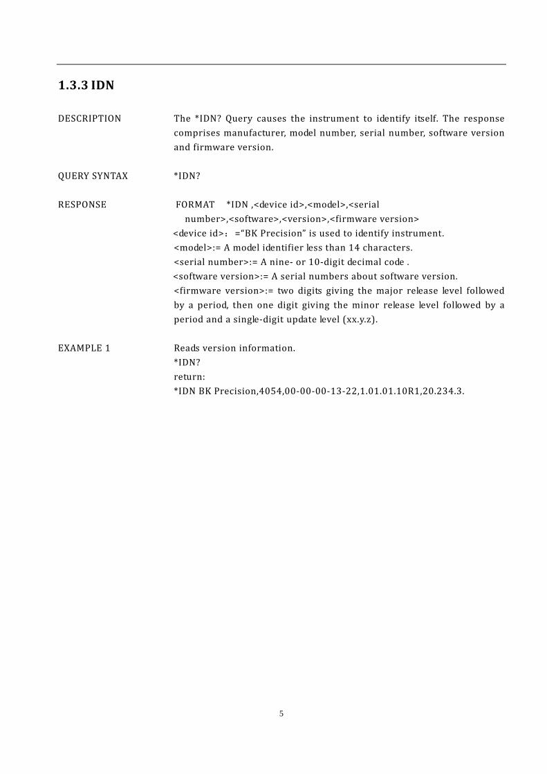
1.3.3 IDN
DESCRIPTION The *IDN? Query causes the instrument to identify itself. The response comprises manufacturer, model number, serial number, software version and firmware version.
QUERY SYNTAX *IDN? RESPONSE FORMAT *IDN ,<device id>,<model>,<serial
number>,<software>,<version>,<firmware version> <device id>:=“BK Precision” is used to identify instrument. <model>:= A model identifier less than 14 characters. <serial number>:= A nine- or 10-digit decimal code . <software version>:= A serial numbers about software version.
<firmware version>:= two digits giving the major release level followed by a period, then one digit giving the minor release level followed by a period and a single-digit update level (xx.y.z).
EXAMPLE 1 Reads version information.
*IDN? return: *IDN BK Precision,4054,00-00-00-13-22,1.01.01.10R1,20.234.3.
6
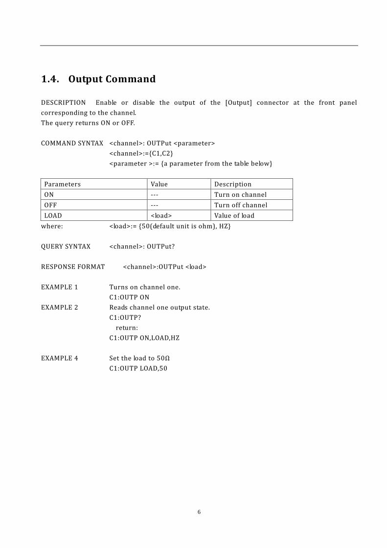
1.4. Output Command
DESCRIPTION Enable or disable the output of the [Output] connector at the front panel corresponding to the channel. The query returns ON or OFF. COMMAND SYNTAX <channel>: OUTPut <parameter> <channel>:={C1,C2}
<parameter >:= {a parameter from the table below}
Parameters Value Description ON --- Turn on channel OFF --- Turn off channel LOAD <load> Value of load
where: <load>:= {50(default unit is ohm), HZ} QUERY SYNTAX <channel>: OUTPut? RESPONSE FORMAT <channel>:OUTPut <load> EXAMPLE 1 Turns on channel one.
C1:OUTP ON EXAMPLE 2 Reads channel one output state.
C1:OUTP? return:
C1:OUTP ON,LOAD,HZ EXAMPLE 4 Set the load to 50Ω C1:OUTP LOAD,50
7
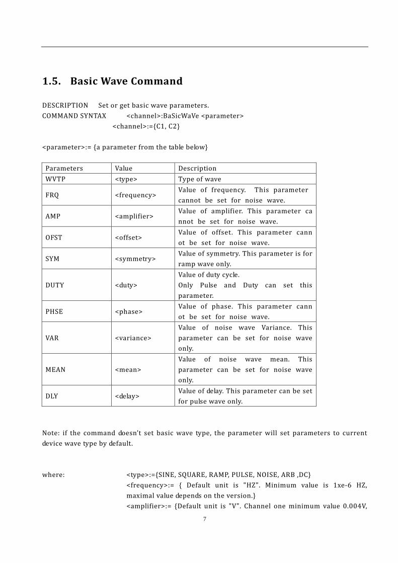
1.5. Basic Wave Command
DESCRIPTION Set or get basic wave parameters. COMMAND SYNTAX <channel>:BaSicWaVe <parameter> <channel>:={C1, C2} <parameter>:= {a parameter from the table below}
Parameters Value Description WVTP <type> Type of wave
FRQ <frequency> Value of frequency. This parameter cannot be set for noise wave.
AMP <amplifier> Value of amplifier. This parameter cannot be set for noise wave.
OFST <offset> Value of offset. This parameter cannot be set for noise wave.
SYM <symmetry> Value of symmetry. This parameter is for ramp wave only.
DUTY <duty> Value of duty cycle. Only Pulse and Duty can set this parameter.
PHSE <phase> Value of phase. This parameter cannot be set for noise wave.
VAR <variance> Value of noise wave Variance. This parameter can be set for noise wave only.
MEAN <mean> Value of noise wave mean. This parameter can be set for noise wave only.
DLY <delay> Value of delay. This parameter can be set for pulse wave only.
Note: if the command doesn’t set basic wave type, the parameter will set parameters to current device wave type by default. where: <type>:={SINE, SQUARE, RAMP, PULSE, NOISE, ARB ,DC}
<frequency>:= { Default unit is "HZ". Minimum value is 1xe-6 HZ, maximal value depends on the version.} <amplifier>:= {Default unit is "V". Channel one minimum value 0.004V,
8
Maximal is 6V. Channel two minimum value 0.004V, Maximal is 20V. } <offset>:= { Default unit is "V". maximal value depends on the maximal value depends on the version.} <duty>:= {If wave type is square, range is from 20% to 80%. if wave type is pulse, range is from 0.1% to 99.9%} <symmetry> :={ 0% to 100%} <phase>:= {0° to 360°} <variance>:= Maximal is 2.222V, minimum value is 0.4mV.The default unit is "V". <mean>:= The range depends on Variance . The default unit is "V". <delay>:= Maximal is Pulse Period, minimum value is 0.Unit is S.
QUERY SYNTAX <channel>:BaSicWaVe? <channel>:={C1, C2}
RESPONSE <channel>:BSWV <type>,<frequency>,<amplifier>,<offset>,<duty>,<symmetry>, <phase>
EXAMPLE 1 change channel one current wave type to ramp. C1:BSWV WVTP,RAMP EXAMPLE 2 Changes current signal frequency of channel one to 2000 Hz.
C1: BSWV FRQ, 2000HZ EXAMPLE 3 set current signal amplifier of channel one. C1: BSWV AMP, 3V EXAMPLE 4 reads channel basic wave parameters from device.
C1:BSWV? Return: C1: BSWV WVTP,SINE,FRQ,1000,AMP,3,OFST,3,PHSE,0
RELATED COMMANDS ARWV, BTWV, CFG, CPL, MDWV, SWWV
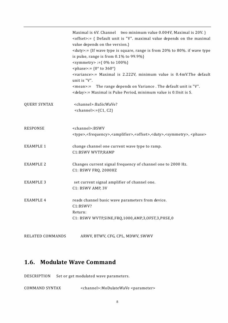
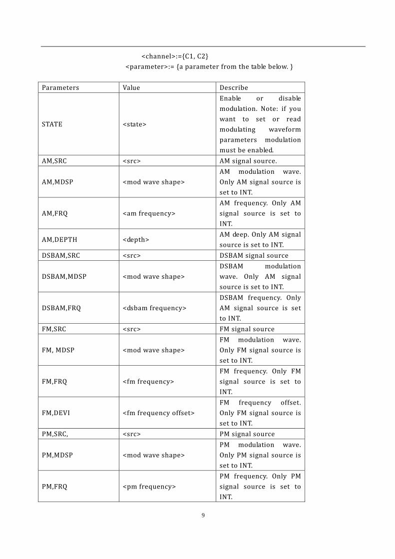
1.6. Modulate Wave Command
DESCRIPTION Set or get modulated wave parameters. COMMAND SYNTAX <channel>:MoDulateWaVe <parameter>
9
<channel>:={C1, C2} <parameter>:= {a parameter from the table below. }
Parameters Value Describe
STATE <state>
Enable or disable modulation. Note: if you want to set or read modulating waveform parameters modulation must be enabled.
AM,SRC <src> AM signal source.
AM,MDSP <mod wave shape> AM modulation wave. Only AM signal source is set to INT.
AM,FRQ <am frequency> AM frequency. Only AM signal source is set to INT.
AM,DEPTH <depth> AM deep. Only AM signal source is set to INT.
DSBAM,SRC <src> DSBAM signal source
DSBAM,MDSP <mod wave shape> DSBAM modulation wave. Only AM signal source is set to INT.
DSBAM,FRQ <dsbam frequency> DSBAM frequency. Only AM signal source is set to INT.
FM,SRC <src> FM signal source
FM, MDSP <mod wave shape> FM modulation wave. Only FM signal source is set to INT.
FM,FRQ <fm frequency> FM frequency. Only FM signal source is set to INT.
FM,DEVI <fm frequency offset> FM frequency offset. Only FM signal source is set to INT.
PM,SRC, <src> PM signal source
PM,MDSP <mod wave shape> PM modulation wave. Only PM signal source is set to INT.
PM,FRQ <pm frequency> PM frequency. Only PM signal source is set to INT.
10
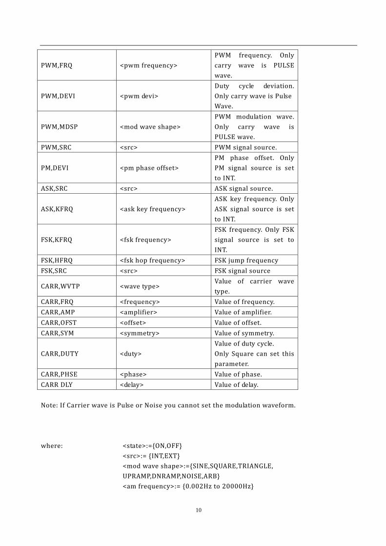
PWM,FRQ <pwm frequency> PWM frequency. Only carry wave is PULSE wave.
PWM,DEVI <pwm devi> Duty cycle deviation. Only carry wave is Pulse Wave.
PWM,MDSP <mod wave shape> PWM modulation wave. Only carry wave is PULSE wave.
PWM,SRC <src> PWM signal source.
PM,DEVI <pm phase offset> PM phase offset. Only PM signal source is set to INT.
ASK,SRC <src> ASK signal source.
ASK,KFRQ <ask key frequency> ASK key frequency. Only ASK signal source is set to INT.
FSK,KFRQ <fsk frequency> FSK frequency. Only FSK signal source is set to INT.
FSK,HFRQ <fsk hop frequency> FSK jump frequency FSK,SRC <src> FSK signal source
CARR,WVTP <wave type> Value of carrier wave type.
CARR,FRQ <frequency> Value of frequency. CARR,AMP <amplifier> Value of amplifier. CARR,OFST <offset> Value of offset. CARR,SYM <symmetry> Value of symmetry.
CARR,DUTY <duty> Value of duty cycle. Only Square can set this parameter.
CARR,PHSE <phase> Value of phase. CARR DLY <delay> Value of delay. Note: If Carrier wave is Pulse or Noise you cannot set the modulation waveform. where: <state>:={ON,OFF} <src>:= {INT,EXT}
<mod wave shape>:={SINE,SQUARE,TRIANGLE, UPRAMP,DNRAMP,NOISE,ARB} <am frequency>:= {0.002Hz to 20000Hz}
11
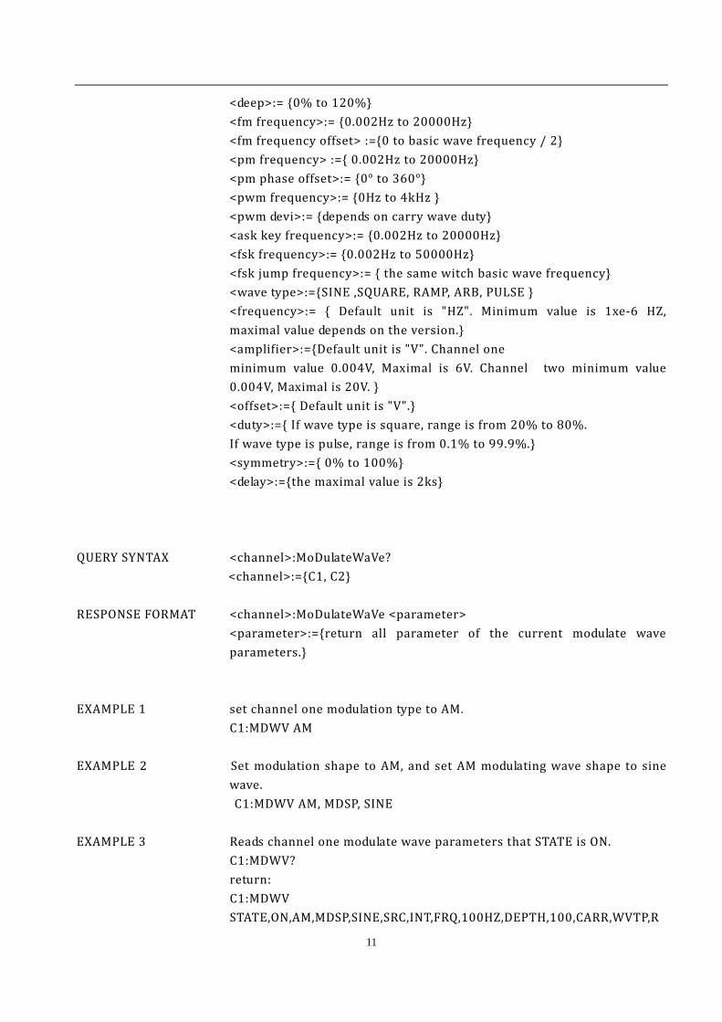
<deep>:= {0% to 120%} <fm frequency>:= {0.002Hz to 20000Hz}
<fm frequency offset> :={0 to basic wave frequency / 2} <pm frequency> :={ 0.002Hz to 20000Hz} <pm phase offset>:= {0° to 360°}
<pwm frequency>:= {0Hz to 4kHz } <pwm devi>:= {depends on carry wave duty}
<ask key frequency>:= {0.002Hz to 20000Hz} <fsk frequency>:= {0.002Hz to 50000Hz}
<fsk jump frequency>:= { the same witch basic wave frequency} <wave type>:={SINE ,SQUARE, RAMP, ARB, PULSE } <frequency>:= { Default unit is "HZ". Minimum value is 1xe-6 HZ, maximal value depends on the version.} <amplifier>:={Default unit is "V". Channel one minimum value 0.004V, Maximal is 6V. Channel two minimum value 0.004V, Maximal is 20V. } <offset>:={ Default unit is "V".} <duty>:={ If wave type is square, range is from 20% to 80%. If wave type is pulse, range is from 0.1% to 99.9%.} <symmetry>:={ 0% to 100%} <delay>:={the maximal value is 2ks}
QUERY SYNTAX <channel>:MoDulateWaVe? <channel>:={C1, C2} RESPONSE FORMAT <channel>:MoDulateWaVe <parameter>
<parameter>:={return all parameter of the current modulate wave parameters.}
EXAMPLE 1 set channel one modulation type to AM. C1:MDWV AM EXAMPLE 2 Set modulation shape to AM, and set AM modulating wave shape to sine
wave. C1:MDWV AM, MDSP, SINE EXAMPLE 3 Reads channel one modulate wave parameters that STATE is ON. C1:MDWV? return:
C1:MDWV STATE,ON,AM,MDSP,SINE,SRC,INT,FRQ,100HZ,DEPTH,100,CARR,WVTP,R
12
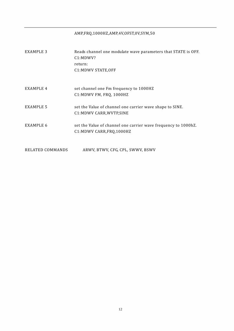
AMP,FRQ,1000HZ,AMP,4V,OFST,0V,SYM,50 EXAMPLE 3 Reads channel one modulate wave parameters that STATE is OFF. C1:MDWV? return:
C1:MDWV STATE,OFF EXAMPLE 4 set channel one Fm frequency to 1000HZ C1:MDWV FM, FRQ, 1000HZ EXAMPLE 5 set the Value of channel one carrier wave shape to SINE. C1:MDWV CARR,WVTP,SINE EXAMPLE 6 set the Value of channel one carrier wave frequency to 1000hZ. C1:MDWV CARR,FRQ,1000HZ RELATED COMMANDS ARWV, BTWV, CFG, CPL, SWWV, BSWV

13
1.7. Sweep Wave Command
DESCRIPTION Set or get sweep wave parameters. COMMAND SYNTAX <channel>:SWeepWaVe <parameter> <channel>:={C1, C2}
<parameter>:= {a parameter from the table below. } Parameters Value Description STATE <state> Turn on or off sweep
wave. Note if you want to set or read sweep wave parameters, you must first enable sweep mode.
TIME <time> Value of sweep time STOP <stop frequency> Value of stop frequency START <start frequency> Value of start frequency TRSR <trigger src> Trigger source TRMD <trigger mode> Value of trigger output. If
TRSR is EXT, the parameter is invalid.
SWMD <sweep mode > Sweep way DIR <direction> Sweep direction EDGE <edge> Value of edge. Only TRSR
is EXT, the parameter is valid.
MTRIG <manual trigger> Make the device once manual trigger. The parameter is valid only when TRSR is set to MAN.
CARR,WVTP <wave type> Value of carrier wave type. CARR,FRQ <frequency> Value of frequency. CARR,AMP <amplifier> Value of amplifier. CARR,OFST <offset> Value of offset. CARR,SYM <symmetry> Value of symmetry.
CARR,DUTY <duty> Value of duty cycle. Only Square can set this parameter.
CARR,PHSE <phase> Value of phase. Note: If Carrier wave is Pulse or Noise, enabling sweep is not allowed.
14
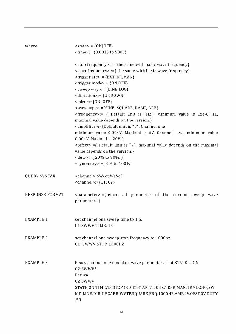
where: <state>:= {ON|OFF} <time>:= {0.001S to 500S}
<stop frequency> :={ the same with basic wave frequency} <start frequency> :={ the same with basic wave frequency}
<trigger src>:= {EXT,INT,MAN} <trigger mode>:= {ON,OFF} <sweep way>:= {LINE,LOG} <direction>:= {UP,DOWN} <edge>:={ON, OFF}
<wave type>:={SINE ,SQUARE, RAMP, ARB} <frequency>:= { Default unit is "HZ". Minimum value is 1xe-6 HZ, maximal value depends on the version.} <amplifier>:={Default unit is "V". Channel one minimum value 0.004V, Maximal is 6V. Channel two minimum value 0.004V, Maximal is 20V. } <offset>:={ Default unit is "V". maximal value depends on the maximal value depends on the version.} <duty>:={ 20% to 80%. } <symmetry>:={ 0% to 100%}
QUERY SYNTAX <channel>:SWeepWaVe? <channel>:={C1, C2} RESPONSE FORMAT <parameter>:={return all parameter of the current sweep wave
parameters.} EXAMPLE 1 set channel one sweep time to 1 S. C1:SWWV TIME, 1S EXAMPLE 2 set channel one sweep stop frequency to 1000hz. C1: SWWV STOP, 1000HZ EXAMPLE 3 Reads channel one modulate wave parameters that STATE is ON. C2:SWWV? Return:
C2:SWWV STATE,ON,TIME,1S,STOP,100HZ,START,100HZ,TRSR,MAN,TRMD,OFF,SWMD,LINE,DIR,UP,CARR,WVTP,SQUARE,FRQ,1000HZ,AMP,4V,OFST,0V,DUTY,50
15
EXAMPLE 4 Reads channel two modulate wave parameters that STATE is OFF. C2:SWWV? Return:
C2:SWWV STATE,OFF
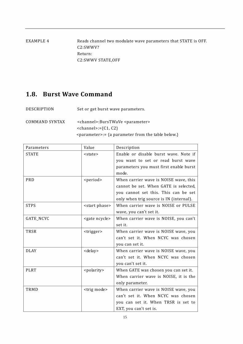
1.8. Burst Wave Command
DESCRIPTION Set or get burst wave parameters. COMMAND SYNTAX <channel>:BursTWaVe <parameter> <channel>:={C1, C2}
<parameter>:= {a parameter from the table below.} Parameters Value Description STATE <state> Enable or disable burst wave. Note if
you want to set or read burst wave parameters you must first enable burst mode.
PRD <period> When carrier wave is NOISE wave, this cannot be set. When GATE is selected, you cannot set this. This can be set only when trig source is IN (internal).
STPS <start phase> When carrier wave is NOISE or PULSE wave, you can’t set it.
GATE_NCYC <gate ncycle> When carrier wave is NOISE, you can’t set it.
TRSR <trigger> When carrier wave is NOISE wave, you can’t set it. When NCYC was chosen you can set it.
DLAY <delay> When carrier wave is NOISE wave, you can’t set it. When NCYC was chosen you can’t set it.
PLRT <polarity> When GATE was chosen you can set it. When carrier wave is NOISE, it is the only parameter.
TRMD <trig mode> When carrier wave is NOISE wave, you can’t set it. When NCYC was chosen you can set it. When TRSR is set to EXT, you can’t set is.

16
EDGE <edge> When carrier wave is NOISE wave, you can’t set it. When NCYC is selected and TRSR is set to EXT, you can set it.
TIME <circle time> When carrier wave is NOISE wave, you can’t set it. When NCYC is selected, you can set it.
MTRIG When TRSR’s parameter be chosen to MAN, that it can be set.
CARR,WVTP <wave type> Value of carrier wave type. CARR,FRQ <frequency> Value of frequency. CARR,AMP <amplifier> Value of amplifier. CARR,OFST <offset> Value of offset. CARR,SYM <symmetry> Value of symmetry.
CARR,DUTY <duty> Value of duty cycle. Only Square can set this parameter.
CARR,PHSE <phase> Value of phase.
CARR,DLY <carr delay> Value of carrier wave delay. This is valid only when the carrier wave is pulse.
CARR VAR <variance> Value of carrier wave variance. This is valid only when the carrier wave is noise.
CARR MEAN <mean> Value of carrier wave mean. This is valid only when the carrier wave is noise.
where: <state>:= {ON,OFF} <period>:= { Default unit is “S ”. 1us to 500s } <start phase>:= {0 to 360} <gate ncycle>:= {GATE,NCYC} <trigger>:= {EXT,INT,MAN} <delay>:= { Default unit is "S". 0s to 500s } <polarity>:= {NEG,POS} <trig mode >:= {RISE,FALL,OFF}
<edge>:= { RISE,FALL} <circle time> :={ 1cycle to 50000 cycle}
<wave type>:={SINE ,SQUARE, RAMP,PULSE,NOISE, ARB} <frequency>:= { Default unit is "HZ". Minimum value is 1xe-6 HZ, maximal value depends on the version.} <amplifier>:={Default unit is "V". Channel one minimum value 0.004V, Maximal is 6V. Channel two minimum value 0.004V, Maximal is 20V. }
17
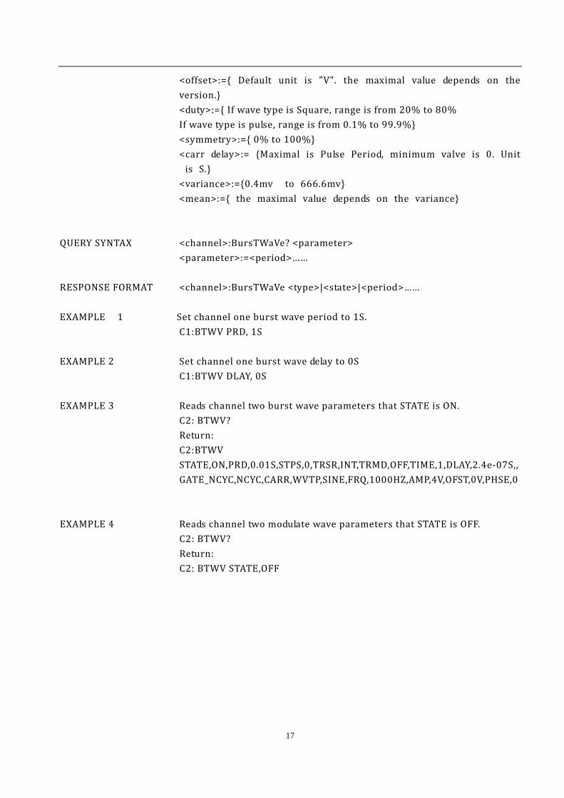
<offset>:={ Default unit is "V". the maximal value depends on the version.} <duty>:={ If wave type is Square, range is from 20% to 80% If wave type is pulse, range is from 0.1% to 99.9%} <symmetry>:={ 0% to 100%} <carr delay>:= {Maximal is Pulse Period, minimum valve is 0. Unit is S.} <variance>:={0.4mv to 666.6mv} <mean>:={ the maximal value depends on the variance}
QUERY SYNTAX <channel>:BursTWaVe? <parameter> <parameter>:=<period>…… RESPONSE FORMAT <channel>:BursTWaVe <type>|<state>|<period>…… EXAMPLE 1 Set channel one burst wave period to 1S. C1:BTWV PRD, 1S EXAMPLE 2 Set channel one burst wave delay to 0S C1:BTWV DLAY, 0S EXAMPLE 3 Reads channel two burst wave parameters that STATE is ON. C2: BTWV? Return:
C2:BTWV STATE,ON,PRD,0.01S,STPS,0,TRSR,INT,TRMD,OFF,TIME,1,DLAY,2.4e-07S,,GATE_NCYC,NCYC,CARR,WVTP,SINE,FRQ,1000HZ,AMP,4V,OFST,0V,PHSE,0
EXAMPLE 4 Reads channel two modulate wave parameters that STATE is OFF. C2: BTWV? Return:
C2: BTWV STATE,OFF

18
1.9. Parameter Copy Command
DESCRIPTION copy channel data. COMMAND SYNTAX PAraCoPy <destinat channle>, <src channle> <destinat channle>:= {C1, C2} <src channle>:= {C1, C2} Note: the parameters C1 and C2 must be set to device together. C1 is destination channel, C2 is source charnel. EXAMPLE 1 Copy parameters from channel one to channel two.
PACP C2,C1 RELATED COMMANDS ARWV, BTWV, CFG, CPL, MDWV, SWWV, BSWV
1.10. Arbitrary Wave Command
DESCRIPTION Change arbitrary wave type. COMMAND SYNTAX <channel>:ARbWaVe {INDEX, NAME} <channel>:={C1, C2}
<index>: 2 to 60 (see blow table what the index number mean.) <name>: see blow table.
Index Name Index Name Index Name Index Name Index Nam
e
2 StairUp 13 LogRise 24 Gmonopu
ls 38 Gausswin 49 Acot
3 StairDn 14 Sqrt 25 Tripuls 39 Triang 50~6
0 User
space
4 StarUD 15 Root3 26 Cardiac 40 blackmanhar
ris
5 PPulse 16 X^2 27 Quake 41 Barthannwin 6 NPulse 17 X^3 28 Chirp 42 Tan 7 Trapezia 18 Sinc 29 Twotone 43 Cot 8 UpRamp 19 Gussian 30 Snr 44 Sec 9 DnRamp 20 Dlorentz 34 Hamming 45 Csc
10 ExpFall 21 Haversi 35 Hanning 46 Asin

19
ne 11 ExpRise 22 Lorentz 36 Kaiser 47 Acos
12 LogFall 23 Gauspul
s 37 BlackMan 48 Atan
QUERY SYNTAX <channel>:ARbWaVe? <channel>:={C1, C2} RESPONSE FORMAT <channel>:ARbWaVe <index> EXAMPLE 1 Set StarUp arbitrary wave output by index.
ARWV INDEX, 2 EXAMPLE 2 Reads system current wave.
ARWV? Return: ARWV INDEX,2,NAME,stairup
EXAMPLE 3 Set Atan arbitrary wave output by name. ARWV NAME, ATAN
RELATED COMMANDS BSWV

20
1.11. Phase Command
DESCRIPTION Set or get phase parameters. COMMAND SYNTAX INVerT <parameter> <parameter>:= {OFF, ON} QUERY SYNTAX INVerT? RESPONSE FORMAT INVERT <parameter> EXAMPLE 1 Set load to invert.
INVT ON
1.12. Sync Command
DESCRIPTION Set signal output from backward panel in phase with forward. COMMAND SYNTAX <channel>: SYNC <parameter> <channel>:={C1,C2} <parameter>:= {ON,OFF} QUERY SYNTAX <channel>:SYNC? RESPONSE FORMAT <channel>:SYNC <parameter> EXAMPLE 1 Sync function on defend of channel one
C1:SYNC ON EXAMPLE 2 Reads channel one sync state.
C1:SYNC? Return: C1:SYNC OFF\n

21
1.13. Configuration Command
DESCRIPTION Changes system load data of power on. COMMAND SYNTAX Sys_CFG<parameter> <parameter>:= {DEFAULT,LAST} QUERY SYNTAX Sys_CFG? RESPONSE FORMAT Sys_CFG <parameter> EXAMPLE 1 Set system load data of power on to last time data.
SCFG LAST
1.14. Buzzer Command
DESCRIPTION Turns on or off buzzer. COMMAND SYNTAX BUZZer <parameter> <parameter>:= {ON,OFF} QUERY SYNTAX BUZZer? RESPONSE FORMAT BUZZer <parameter> EXAMPLE 1 Turns on buzzer.
BUZZ ON
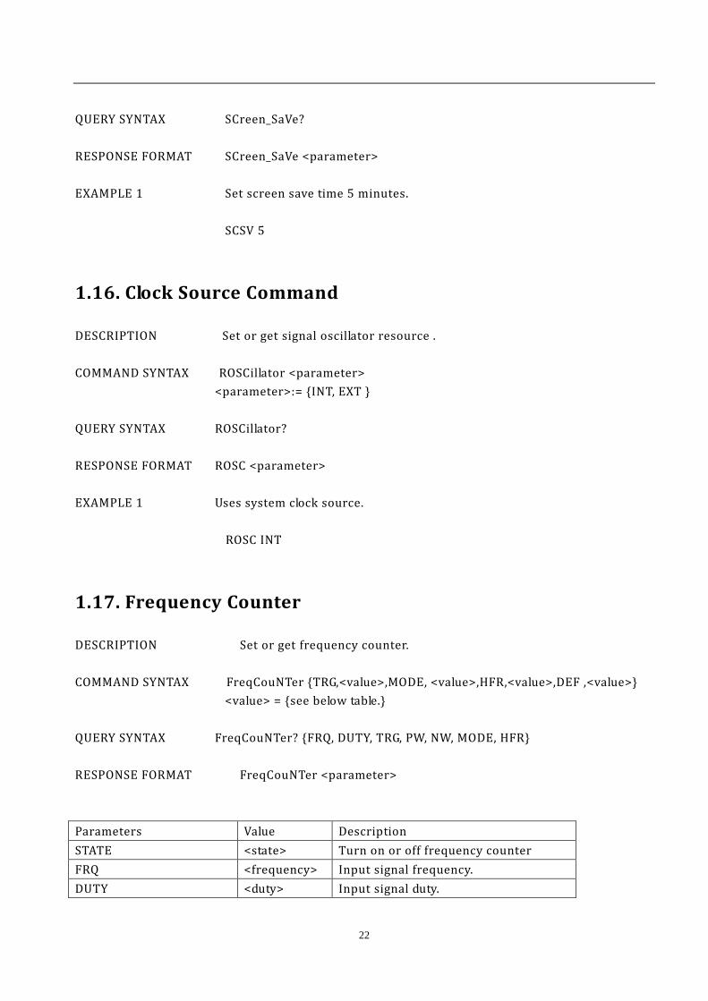
1.15. Screen Save Command
DESCRIPTION Turns on or off Screen Save. COMMAND SYNTAX SCreen_SaVe <parameter> <parameter>:= {OFF,1,5,15,30,60,120,300, Unit is minute}
22
QUERY SYNTAX SCreen_SaVe? RESPONSE FORMAT SCreen_SaVe <parameter> EXAMPLE 1 Set screen save time 5 minutes.
SCSV 5
1.16. Clock Source Command
DESCRIPTION Set or get signal oscillator resource . COMMAND SYNTAX ROSCillator <parameter> <parameter>:= {INT, EXT } QUERY SYNTAX ROSCillator? RESPONSE FORMAT ROSC <parameter> EXAMPLE 1 Uses system clock source.
ROSC INT
1.17. Frequency Counter
DESCRIPTION Set or get frequency counter. COMMAND SYNTAX FreqCouNTer {TRG,<value>,MODE, <value>,HFR,<value>,DEF ,<value>}
<value> = {see below table.} QUERY SYNTAX FreqCouNTer? {FRQ, DUTY, TRG, PW, NW, MODE, HFR} RESPONSE FORMAT FreqCouNTer <parameter> Parameters Value Description STATE <state> Turn on or off frequency counter FRQ <frequency> Input signal frequency. DUTY <duty> Input signal duty.
23
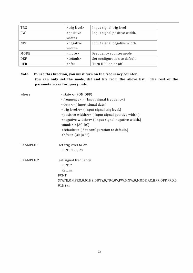
TRG <trig level> Input signal trig level. PW <positive
width> Input signal positive width.
NW <negative width>
Input signal negative width.
MODE <mode> Frequency counter mode. DEF <default> Set configuration to default. HFR <hfr> Turn HFR on or off Note: To use this function, you must turn on the frequency counter. You can only set the mode, def and hfr from the above list. The rest of the
parameters are f or query only.
where: <state>:= {ON|OFF}
<frequency>:= {Input signal frequency.} <duty>:={ Input signal duty.} <trig level>:= { Input signal trig level.} <positive width>:= { Input signal positive width.} <negative width>:= { Input signal negative width.} <mode>:={AC|DC} <default>:= { Set configuration to default.} <hfr>:= {ON|OFF} EXAMPLE 1 set trig level to 2v.
FCNT TRG, 2v EXAMPLE 2 get signal frequency.
FCNT? Return:
FCNT STATE,ON,FRQ,0.01HZ,DUTY,0,TRG,0V,PW,0,NW,0,MODE,AC,HFR,OFF,FRQ,0.01HZ\n
24
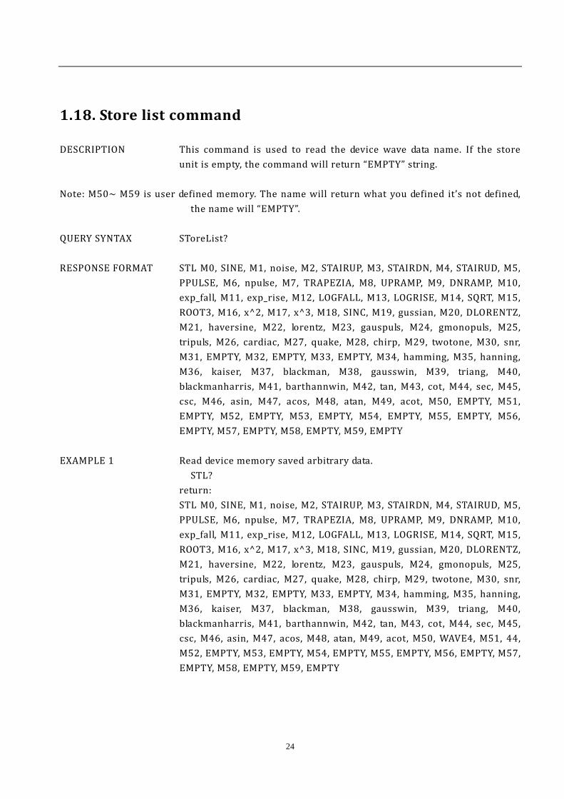
1.18. Store list command
DESCRIPTION This command is used to read the device wave data name. If the store unit is empty, the command will return “EMPTY” string.
Note: M50~ M59 is user defined memory. The name will return what you defined it’s not defined,
the name will “EMPTY”. QUERY SYNTAX SToreList? RESPONSE FORMAT STL M0, SINE, M1, noise, M2, STAIRUP, M3, STAIRDN, M4, STAIRUD, M5,
PPULSE, M6, npulse, M7, TRAPEZIA, M8, UPRAMP, M9, DNRAMP, M10, exp_fall, M11, exp_rise, M12, LOGFALL, M13, LOGRISE, M14, SQRT, M15, ROOT3, M16, x^2, M17, x^3, M18, SINC, M19, gussian, M20, DLORENTZ, M21, haversine, M22, lorentz, M23, gauspuls, M24, gmonopuls, M25, tripuls, M26, cardiac, M27, quake, M28, chirp, M29, twotone, M30, snr, M31, EMPTY, M32, EMPTY, M33, EMPTY, M34, hamming, M35, hanning, M36, kaiser, M37, blackman, M38, gausswin, M39, triang, M40, blackmanharris, M41, barthannwin, M42, tan, M43, cot, M44, sec, M45, csc, M46, asin, M47, acos, M48, atan, M49, acot, M50, EMPTY, M51, EMPTY, M52, EMPTY, M53, EMPTY, M54, EMPTY, M55, EMPTY, M56, EMPTY, M57, EMPTY, M58, EMPTY, M59, EMPTY
EXAMPLE 1 Read device memory saved arbitrary data.
STL? return:
STL M0, SINE, M1, noise, M2, STAIRUP, M3, STAIRDN, M4, STAIRUD, M5, PPULSE, M6, npulse, M7, TRAPEZIA, M8, UPRAMP, M9, DNRAMP, M10, exp_fall, M11, exp_rise, M12, LOGFALL, M13, LOGRISE, M14, SQRT, M15, ROOT3, M16, x^2, M17, x^3, M18, SINC, M19, gussian, M20, DLORENTZ, M21, haversine, M22, lorentz, M23, gauspuls, M24, gmonopuls, M25, tripuls, M26, cardiac, M27, quake, M28, chirp, M29, twotone, M30, snr, M31, EMPTY, M32, EMPTY, M33, EMPTY, M34, hamming, M35, hanning, M36, kaiser, M37, blackman, M38, gausswin, M39, triang, M40, blackmanharris, M41, barthannwin, M42, tan, M43, cot, M44, sec, M45, csc, M46, asin, M47, acos, M48, atan, M49, acot, M50, WAVE4, M51, 44, M52, EMPTY, M53, EMPTY, M54, EMPTY, M55, EMPTY, M56, EMPTY, M57, EMPTY, M58, EMPTY, M59, EMPTY

25
1.19. Get arbitrary wave data command
DESCRIPTION This command changes the user defined memory unit arbitrary wave data.
COMMAND SYNTAX WaVe_DaTa <address>,<parameter> <address>:= {M50~M59}
<parameter>:= {a parameter from the table below. }
Parameters Value Description WVNM <wavename> arbitrary wave name
TYPE <type> Arbitrary wave type .Note the value has to be set to 5.
LENGTH <length> Arbitrary wave data Length. It must be set to "32KB"
FREQ <frequency> Arbitrary wave frequency. AMPL <amplifier> Value of amplify. OFST <offset> Value of offset. PHASE <phase> Value of phase. WAVEDATA <wavedata> Wave data. Not: All parameters must be set in one command. If not, the command will not execute successfully. QUERY SYNTAX WaVe_DaTa RESPONSE FORMAT WaVe_DaTa <parameter> EXAMPLE Read device memory saved arbitrary data.
WVDT M50? return: WVDT POS, M51, WVNM, WAVE02, LENGTH, 32KB, TYPE, 5, WAVEDATA,\x00?\x03\x00\x06\x00\t\x00\f \x00\x0f \x00\x12\x00\x15\x00\x19\x00\x1c\x00\x1f \x00"\x00%\x00(\x00+\x00/\x002\x005\x008\x00;\x00>\x00A\x00E\x00H\x00K\x00N\x00Q\x00T\x00W\x00[\x00^\x00a\x00d\x00g\x00j\x00m\x00q\x00t\x00w\x00z\x00}\x00\x80\x00\x83\x00\x87\x00\x8a\x00\x8d\x00\x90\x00\x93\x00\x96\x00\x99\x00\x9d\x00\xa0\x00\xa3\x00\xa6\x00\xa9\x00\xac\x00\xaf \x00\xb3\x00\xb6\x00\xb9\x00\xbc\x00\xbf \x00\xc2\x00\xc5\x00\xc9\x00\xcc\x00\xcf \x00\xd2\x00\xd5\x00\xd8\x00\xdb\x00\xdf \x00\xe2\x00\xe5\x00\xe8\x00\xeb\x00\xee\x00\xf1\x00\xf 4\x00\xf 8\x00\xfb\x00\xfe\x00\x01\x01\x04\x01\a\x01\n

26
\x01\x0e\x01\x11\x01\x14\x01\x17\x01\x1a\x01\x1d\x01 \x01$\x01'\x01*\x01-\x010\x013\x016\x01:\x01=\x01@\x01C\x01F\x01I\x01L\x01P\x01S\x01V\x01Y\x01\\\x01_\x01b\x01f \x01i\x01l\x01o\x01r\x01u\x01x\x01{\x01\x7f \x01\x82\x01\x85\x01\x88\x01\x8b\x01\x8e\x01\x91\x01\x95\x01\x98\x01\x9b\x01\x9e\x01\xa1\x01\xa4\x01\xa7\x01\xab\x01\xae\x01\xb1\x01\xb4\x01\xb7\x01\xba\x01\xbd\x01\xc0\x01\xc4\x01\xc7\x01\xca\x01\xcd\x01\xd0\x01\xd3\x01\xd6\x01\xda\x01\xdd\x01\xe0\x01\xe3\x01\xe6\x01\xe9\x01\xec\x01\xf0\x01\xf3\x01\xf 6\x01\xf9\x01\xfc\x01\xff \x01\x02\x02\x05\x02\t\x02\f \x02\x0f \x02\x12\x02\x15\x02\x18\x02\x1b\x02\x1f \x02"\x02%\x02(\x02+\x02.\x021\x025\x028\x02;\x02>\x02A\x02D\x02G\x02J\x02N\x02Q\x02T\x02W\x02Z\x02]\x02`\x02d\x02g\x02j\x02m\x02p\x02s\x02v\x02y\x02}\x02\x80\x02\x83\x02\x86\x02\x89\x02\x8c\x02\x8f \x02\x92\x02\x96\x02\x99\x02\x9c\x02\x9f \x02\xa2\x02\xa5\x02\xa8\x02\xac\x02\xaf \x02\xb2\x02\xb5\x02\xb8\x02\xbb\x02\xbe\x02\xc1\x02\xc5\x02\xc8\x02\xcb\x02\xce\x02\xd1\x02\xd4\x02\xd7\x02\xda\x02\xde\x02\xe1\x02\xe4\x02\xe7\x02\xea\x02\xed\x02\xf0\x02\xf 4\x02\xf 7\x02\xfa\x02\xfd\x02\x00\x03\x03\x03\x06\x03\t\x03\r \x03\x10\x03\x13\x03\x16\x03\x19\x03\x1c\x03\x1f \x03"\x03&\x03)\x03,\x03/\x032\x035\x038\x03;\x03?\x03B\x03E\x03H\x03K\x03N\x03Q\x03T\x03X\x03[\x03^\x03a\x03d\x03g\x03j\x03m\x03q\x03t\x03w\x03z\x03}\x03\x80\x03\x83\x03\x86\x03\x8a\x03\x8d\x03\x90\x03\x93\x03\x96\x03\x99\x03\x9c\x03\x9f \x03\xa2\x03\xa6\x03\xa9\x03\xac\x03\xaf\x03\xb2\x03\xb5\x03\xb8\x03\xbb\x03\xbf \x03\xc2\x03\xc5\x03\xc8\x03\xcb\x03\xce\x03\xd1\x03\xd4\x03\xd8\x03\xdb\x03\xde\x03\xe1\x03\xe4\x03\xe7\x03\xea\x03\xed\x03\xf0\x03\xf 4\x03\xf 7\x03\xfa\x03\xfd\x03\x00\x04\x03\x04\x06\x04\t\x04\r \x04\x10\x04\x13\x04\x16\x04\x19\x04\x1c\x04\x1f \x04"\x04%\x04)\x04,\x04/\x042\x045\x048\x04;\x04>\x04A\x04E\x04H\x04K\x04N\x04Q\x04T\x04W\x04Z\x04]\x04a\x04d\x04g\x04j\x04m\x04p\x04s\x04v\x04y\x04}\x04\x80\x04\x83\x04\x86\x04\x89\x04\x8c\x04\x8f \x04\x92\x04\x95\x04\x99\x04\x9c\x04\x9f \x04\xa2\x04\xa5\x04\xa8\x04\xab\x04\xae\x04\xb1\x04\xb5\x04\xb8\x04\xbb\x04\xbe\x04\xc1\x04\xc4\x04\xc7\x04\xca\x04\xcd\x04\xd1\x04\xd4\x04\xd7\x04\xda\x04\xdd\x04\xe0\x04\xe3\x04\xe6\x04\xe9\x04\xec\x04\xf0\x04\xf3\x04\xf 6\x04\xf9\x04\xfc\x04\xff \x04\x02\x05\x05\x05\b\x05\v\x05\x0f \x05\x12\x05\x15\x05\x18\x05\x1b\x05\x1e\x05!\x05$\
27
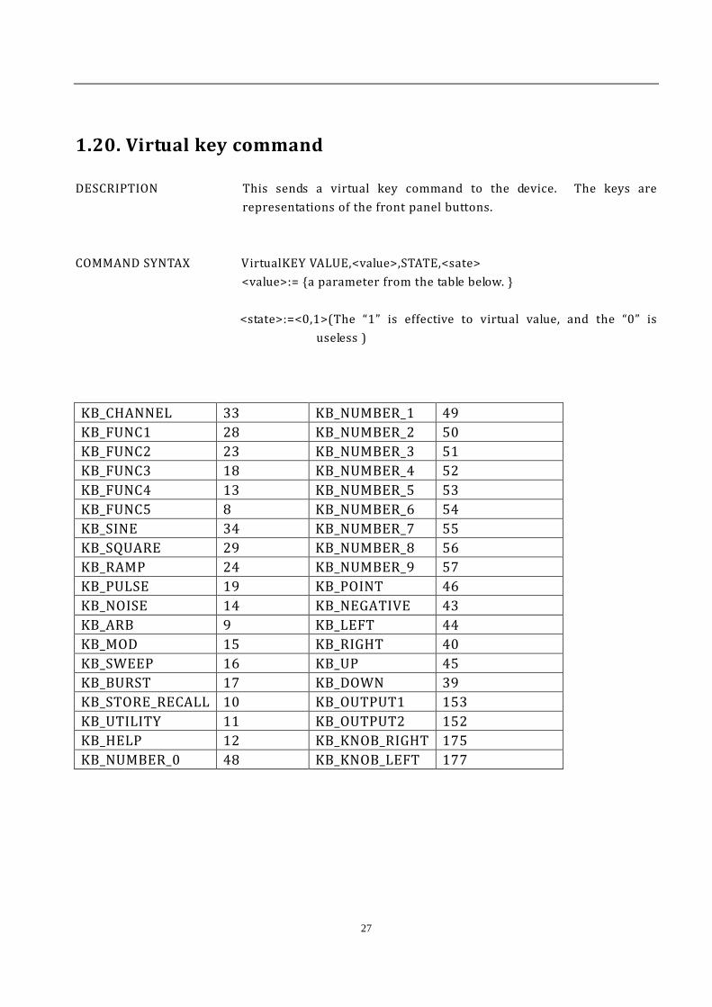
1.20. Virtual key command
DESCRIPTION This sends a virtual key command to the device. The keys are representations of the front panel buttons.
COMMAND SYNTAX VirtualKEY VALUE,<value>,STATE,<sate>
<value>:= {a parameter from the table below. } <state>:=<0,1>(The “1” is effective to virtual value, and the “0” is
useless ) KB_CHANNEL 33 KB_NUMBER_1 49 KB_FUNC1 28 KB_NUMBER_2 50 KB_FUNC2 23 KB_NUMBER_3 51 KB_FUNC3 18 KB_NUMBER_4 52 KB_FUNC4 13 KB_NUMBER_5 53 KB_FUNC5 8 KB_NUMBER_6 54 KB_SINE 34 KB_NUMBER_7 55 KB_SQUARE 29 KB_NUMBER_8 56 KB_RAMP 24 KB_NUMBER_9 57 KB_PULSE 19 KB_POINT 46 KB_NOISE 14 KB_NEGATIVE 43 KB_ARB 9 KB_LEFT 44 KB_MOD 15 KB_RIGHT 40 KB_SWEEP 16 KB_UP 45 KB_BURST 17 KB_DOWN 39 KB_STORE_RECALL 10 KB_OUTPUT1 153 KB_UTILITY 11 KB_OUTPUT2 152 KB_HELP 12 KB_KNOB_RIGHT 175 KB_NUMBER_0 48 KB_KNOB_LEFT 177

V042413
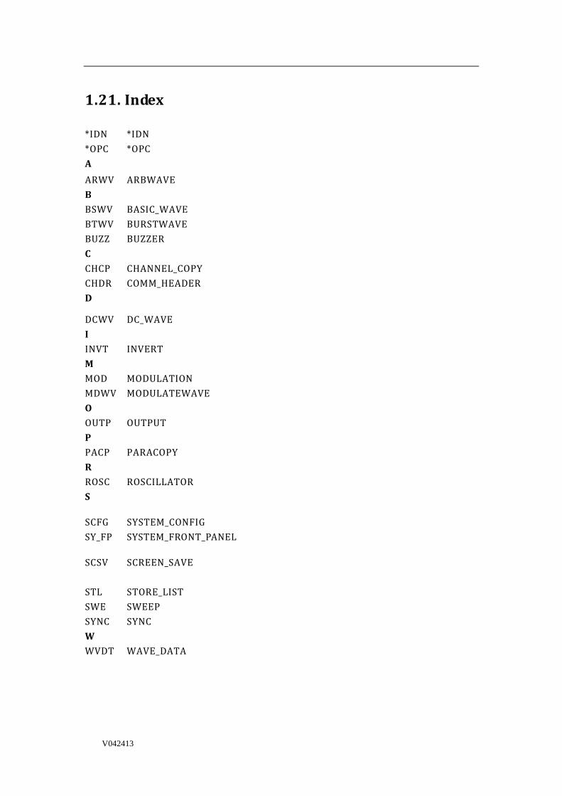
1.21. Index
*IDN *IDN *OPC *OPC A ARWV ARBWAVE B BSWV BASIC_WAVE BTWV BURSTWAVE BUZZ BUZZER C CHCP CHANNEL_COPY CHDR COMM_HEADER D
DCWV DC_WAVE I INVT INVERT M MOD MODULATION MDWV MODULATEWAVE O OUTP OUTPUT P PACP PARACOPY R ROSC ROSCILLATOR S
SCFG SYSTEM_CONFIG SY_FP SYSTEM_FRONT_PANEL
SCSV SCREEN_SAVE STL STORE_LIST SWE SWEEP SYNC SYNC W WVDT WAVE_DATA