Embed Size (px)
Citation preview

66251857 - V1.5 - 31/12/21- 1 -
4000 Series
Art. 4304/4304X - Installation instructions
DC
A B
Fig. 1 Front
ON
1 2 3 4 5 6 7 8
STEEL
MATTE
ALIHIGH BRASS
GUN METAL
4304X-14304X-0
4304X-2
EXPANSIONBUTTONS
NC
VAU
X+CCN
OG
ND
PTE
BU
SB
US
ABGN
D
RS485
4304-14304-0
4304-2
Made in Italy
E
M
F
G
H
L
I
Fig. 2 Back
DESCRIPTIONSpeaker unit module for VX2300 digital system.Art. 4304X versions are also equiped with a built-in proximity key reader and programming modes.The unit circuitry incorporates:• The transmitting amplifier with microphone and volume control;• The receiving amplifier with volume control;• The audio balance circuit with “BALANCE” control;• The enslavement relay to enable the electric lock (3 contacts:
common, normally open and normally closed). It can work also as capacitor discharge to supply directly the electric lock;
• The call buttons from (0, 1 or 2 depending on the module version;• The illumination LEDs for the card name holder.
LEGENDA LoudspeakerB Operation LEDsC Card name holder with built
in-in proximity key reader (only Art. 4304X versions)
D Call push button
E BalanceF Loudspeaker volumeG Microphone volumeH 8 way dip-switchI RS485 connection terminals
(only Art. 4304X versions)L IDC male connectorsM Connection terminals
AVAILABLE VERSIONS
Art. 4304-0 Art. 4304X-0
1
Art. 4304-1Art. 4304X-1
12
Art. 4304-2Art. 4304X-2
LEDSThe first LED (red), if switched ON, indicates that it is not possible to make a call because a call or a conver-sation is in progress (from the outdoor station from which you are calling or from another outdoor station on systems with multiple entrances). The second LED (red), if switched ON, indicates that a call is in progress. The LED will be switched OFF when the call is answered.The third LED (yellow), if switched ON, indicates that it is possible to speak. The LED will be switched OFF at the end of conversation (or at the end of the conversation time).The fourth LED (green), if switched ON, means that the door lock has been operated. It will be switched OFF at the end of the “door opening” time.
CONTROLS
BalancePrevent Larsen effect on bidirectional audio conversation.
Loudspeaker volumeAdjust the loudspeaker volume.Rotate clockwise to increase or anti-clockwise to decrease
Microphone volumeAdjust the microphone volume.Rotate clockwise to increase or anti-clockwise to decrease
Art. 4304 Speaker unit
Art. 4304X Speaker unit with built-in proximity key reader

66251857 - V1.5 - 31/12/21- 2 -
4000 Series
Art. 4304/4304X - Installation instructions
PROGRAMMINGThe programming consists of the following settings:• Unit ID (1..15);• Door opening time (2 or 6 seconds);• Conversation time (1 or 2 minutes);• Addressing order of the buttons.• Programming mode for Art. 4304X versions.The settings are carried out through the 8 way dip-switch (reference H on Fig. 2) accessible from the rear side of the module.
PROGRAMMING THE UNIT IDSwitch Nr.1 Nr.2 Nr.3 Nr.4 ID
ON
1 3 5 72 4 6 8OFF OFF OFF OFF 1
ON
1 3 5 72 4 6 8ON OFF OFF OFF 2
ON
1 3 5 72 4 6 8OFF ON OFF OFF 3
ON
1 3 5 72 4 6 8ON ON OFF OFF 4
ON
1 3 5 72 4 6 8OFF OFF ON OFF 5
ON
1 3 5 72 4 6 8ON OFF ON OFF 6
ON
1 3 5 72 4 6 8OFF ON ON OFF 7
ON
1 3 5 72 4 6 8ON ON ON OFF 8
ON
1 3 5 72 4 6 8OFF OFF OFF ON 9
ON
1 3 5 72 4 6 8ON OFF OFF ON 10
ON
1 3 5 72 4 6 8OFF ON OFF ON 11
ON
1 3 5 72 4 6 8ON OFF ON ON 12
ON
1 3 5 72 4 6 8OFF OFF ON ON 13
ON
1 3 5 72 4 6 8ON OFF ON ON 14
ON
1 3 5 72 4 6 8OFF ON ON ON 15
PROGRAMMING THE DOOR OPENING TIMESwitch Nr.5 Setting Up
ON
1 3 5 72 4 6 8OFF = 2 seconds
ON
1 3 5 72 4 6 8ON = 6 seconds
PROGRAMMING THE CONVERSATION TIMESwitch Nr.6 Setting Up
ON
1 3 5 72 4 6 8OFF = 1 minute
ON
1 3 5 72 4 6 8ON = 2 minutes
PROGRAMMING THE ADDRESSING ORDER OF THE BUTTONS
Switch Nr.7Setting Up
Button matrix Internal buttonsON
1 3 5 72 4 6 8OFF = 1 - 40 = 1, 2
ON
1 3 5 72 4 6 8ON = 41 - 80 = 41, 42
PROGRAMMING MODES (ONLY ART. 4304X VERSIONS)Switch 8 sets the programming mode: "Standard" (switch in OFF position) or "Advanced" (switch in ON position).In "Standard" mode settings are made by switches from 1 to 7.In "Advanced" mode all programming is made via the "VX2X00 Programmer" PC software connected to RS485 via an Art. 481 in-terface. Please note that in this case the programming made by switches from 1 to 7 wil be ignored.
Switch Nr.8 Setting UpON
1 3 5 72 4 6 8OFF "Standard" programming mode
ON
1 3 5 72 4 6 8ON "Advanced" programming mode
Art. 4304 Speaker unit with built-in cameraArt. 4304X Speaker unit with built-in camera & proximity key reader

66251857 - V1.5 - 31/12/21- 3 -
4000 Series
Art. 4304/4304X - Installation instructions
Art. 4304 Speaker unit with built-in cameraArt. 4304X Speaker unit with built-in camera & proximity key reader
RS485 CONNECTIONWith switch 8 in ON position the module can be connected using an RS485 bus connection via an RS485 to USB converter (Art. 481) as shown in Fig. 3.This method of connection can be used for programming and setup of the module.Over distances shorter than 500mt the bus termination jumper on the Art. 481 can be set to the OPEN posi-tion.
ON
1 2 3 4 5 6 7 8
STEEL
MATTE
ALIHIGH BRASS
GUN METAL
4304X-14304X-0
4304X-2
EXPANSIONBUTTONS
NC
VAU
X+CCN
OG
ND
PTE
BU
SB
US
ABGN
D
RS485
4304-14304-0
4304-2
Made in Italy
485 / 232
RS-485
USB-PC
A B GND
RS-232
Art. 481USB-Serial Converter
OpenClose
BUSTermination
switch to RS485 position
RS485 cable
USB cable
PC
BUS termination jumperin the closed position
Fig. 3
404x FLAT CABLE CONNECTIONTo power the button module connect one of the inbuilt IDC male connectors to the IDC male connector of the camera unit mod-ule through the flat cable provided. Further buttons expansion modules can be connected to the free IDC male connector of the previous expansion module (Fig. 4).
ORArt. CFL1717 cm lenght flat cable(Supplied)
Art. CFL4545 cm lenght flat cable(to be ordered separately)
Fig. 4
J2 AND J1 JUMPERS BACKLIT LEDS SETTINGSFor proper functioning please set J2 and J1 jumpers of any connected button expansion module Art. 404x as shown in the table below.NOTE: when more modules are connected, following the connection order, every two modules, the previous must be set as module 1 while the next must be set as module 2.
USING ONE SINGLE EXPANSION BUTTON MODULEJ2 J1
B A B A
USING A COUPLE EXPANSION BUTTON MODULES
1
2
Expansion button module 1J2 J1
B A B A
Art. 4304 - Art. 4304X
Expansion button module 2J2 J1
B A B A
NOTE: to connect more than 2 expansion button modules, please refer also to the installation diagrams.

66251857 - V1.5 - 31/12/21- 4 -
4000 Series
Art. 4304/4304X - Installation instructions
HOW TO CONNECT AN ELECTRIC LOCKThe “door-open” relay can operate either as “dry contact” or “capacitive discharge” mode.• In “dry contact” operation mode the relay works in a traditional way, a power supply or a power source is needed to operate the
lock (12-24Vac/dc 2A max), and activation lasts according to the door opening time programmed.• In “capacitive discharge” operation mode the relay’s contacts, when active, supply directly the lock (12Vac/dc 1A max) for a mo-
ment. You don’t need a power supply for the lock and the door opening time programmed does not affect the activation time.A possibile deterioration of the mechanical performance of the electric lock, might cause the “capacitive discharge” to malfunction in time. In case the electric lock is used in very dusty environments or in peculiar climate conditions, we suggest to use the “open door” relay in “dry contact” mode.
12Vac/dc 1A Max
Fig. 5 Using capacitive discharge
12Vac 1.6A Max using Art. 32124Vac/dc 2A Max using other power supplies
Fig. 6 Using separate P.S.U.
OPERATIONOnce the device has been programmed and connected correctly, it will generate upon each pressing of a push button, a code correspond-ing to the PHONE ID (address programmed on the 8 way dip-switch inside each telephone) of the telephone being called.TO CALL A USERPress the relevant button to call the user: 2 quick beeps will indicate if the system is busy, otherwise the call will be signalled by aslow intermittent acoustic signal until the call is answered, the conversation time expires (programmable time) or the call is inter-rupted by pressing a push button for a minimum of 2 seconds. A short intermittent acoustic signal plus the relevant LED switched ON indicates that the door is open. If a wrong push button is pressed or if there is no answer, a new call will cancel the previous one.
MOUNTING NOTESWhen an expansion button module (Art. 404x) is used combined with speaker units with inbuilt camera (Art. 4304-1, Art. 4304-2, Art. 4304X-1, Art. 4304X-2) remember to set the expansion modules properly in order to avoid overwriting the addresses; indeed the inbuilt buttons ad-dresses are already set (Fig. 7).
1
6
7
8
9
10
1
2
6
7
8
9
10
Art. 4304 -Art. 4304X switch
Nr.7
ON
1 2 3 4 5 6 7 8OFF
Art. 404x jumper
n=5R
Fig. 7
Art. 4304 Speaker unit with built-in cameraArt. 4304X Speaker unit with built-in camera & proximity key reader

66251857 - V1.5 - 31/12/21- 5 -
4000 Series
Art. 4304/4304X - Installation instructions
PROGRAMMING TAGS (ONLY ART. 4304X VERSIONS)MASTER TAGThe external module is supplied with a master tag. The master tag is programmed in-factory, it is white to easily stand out. This tag enables user tags to be programmed or cleared.If the master tag is lost, a new one will have to be ordered and a specific procedure performed to program it on the external module. In this instance, it will be necessary to reprogram all the user tags.
USER TAGThe user tags can be programmed on the external module using the master tag to access programming mode:
1. Place the master tag in front of the tag reader.↪The external module emits two high-pitched “bip”. BIP BIP
2. Press the call button (the lower call button in the case of a 2-button external module). If the speaker unit has no button, press the external button configured as address one: that is the button at the bottom of the extension module configured as addresses interval from 1 to 5.↪The external module emits a low-pitched continuous “beeping” sound. BIIIIIIP
3. Release the call button.↪The low-pitched “beeping” sound stops.
4. Place the user tag to be programmed in front of the tag reader.↪The external module emits a high-pitched “beeping” sound, the tag is programmed. If you do
not remove the tag quickly, may be emitted the alert for an already programmed tag. BIP
5. Repeat the step 4 for each tag to program.
Note: the external module emits three low-pitched “beeping” sounds if an already programmed tag is placed in front of the tag reader. BIP BIP BIP
Note: the external module emits three high-pitched “beeping” sounds to indicate that its memory is full (50 tags maximum). In this instance, it is not possible to program new tags. BIP BIP BIP
6. To exit programming mode: » place the master tag in front of the tag reader, or » wait 10 seconds after the most recent programming operation.↪ The external module emits two low-pitched “beeping” sounds in order to indicate
that it is in operational mode.
BIP BIP
USING TAGSPlace a tag in front of the tag reader:
↪ If the tag is programmed, the external module emits two high-pitched “beeping” sounds and its relay is activated. BIP BIP
↪ If the tag is not programmed, the external module emits three low-pitched “beeping” sounds and its relay is not activated. BIP BIP BIP
CLEARING USER TAGS
The following procedure will clear the programming on all user tags.
Clearing the user tag programming is carried out on the external module using the master tag to run the procedure:
1. Place the master tag in front of the tag reader.↪The external module emits two high-pitched “bip”. BIP BIP
2. Press the call button (the lower call button in the case of an external 2-button module) BIP.↪The external module emits a low-pitched continuous “beeping” sound. BIIIIIIP
3. Release the call button.↪The low-pitched “beeping” sound stops.
4. Press and hold down the call button and place the master tag in front of the tag reader.↪The external module emitts two low-pitched “beeping” sounds, all user tags have been
cleared and the external module exits programming mode.BIP BIP
Art. 4304 Speaker unit with built-in cameraArt. 4304X Speaker unit with built-in camera & proximity key reader

66251857 - V1.5 - 31/12/21- 6 -
4000 Series
Art. 4304/4304X - Installation instructions
REPROGRAMMING A MASTER TAGSIf the master tag is lost or damaged, a new one can be programmed using the following procedure:
1. Switch off the power.
2. Open the external module housing.
3. Bridge the PTE and GND terminals or press and hold down the “press to exit” button, if this is wired to the external module (refer to the external module's instructions).
ON
1 2 3 4 5 6 7 8
STEEL
MATTE
ALIHIGH BRASS
GUN METAL
4304X-14304X-0
4304X-2
EXPANSIONBUTTONS
NC
VAU
X+CCN
OG
ND
PTE
BU
SB
US
ABGN
D
RS485
4304-14304-0
4304-2
Made in Italy
4. Switch the power back on.↪The external module emits a high-pitched “beeping” sound. BIP
5. Remove the short between the PTE and GND terminals or release the “press to exit” button.↪The external module emits a high-pitched "beeping" sound. BIP
6. Place the master tag in front of the tag reader.↪The external module emits two high-pitched “beeping” sounds, then two low-pitched
“beeping” sounds, the master tag is programmed, all user tags have been deprogrammed and the external module exits programming mode.
BIP BIP
BIP BIP
7. Close the external module's housing.
HOW TO REMOVE/INSERT THE CARD NAME HOLDER• To avoid damage to the module front plate, mask the side that
will be in contact with the screwdriver blade;• Insert the screwdriver (flat side) into the card-holder hole as
shown in Fig. 8;• Move the screwdriver to the left as shown in Fig. 9 to extract
the card name holder;• Edit the card name then replace it inside the holder and refit:
insert the holder inside its housing from the left or right side then push the other side until it clips into place. Fig. 8 Fig. 9
ADHESIVE GASKET PLACEMENTApply the Y seal as shown in Fig. 10.
ANTI-TAMPERING LOCKS FIXINGFit the anti-tampering locks W as shown in Fig. 11.
Y
G
Fig. 10
W
Fig. 11
Art. 4304 Speaker unit with built-in cameraArt. 4304X Speaker unit with built-in camera & proximity key reader

66251857 - V1.5 - 31/12/21- 7 -
4000 Series
Art. 4304/4304X - Installation instructions
Art. 4304 Speaker unit with built-in cameraArt. 4304X Speaker unit with built-in camera & proximity key reader
CONNECTION TERMINALS SIGNALSART. 4304 VERSIONS
BUSBUS Connection terminals
BUSPTE “Push to exit” active low input
GND GroundNO Door open relay normally open contact Max 12-24
Vac/dc 2AC Door open relay common contact+C Electric lock capacitor discharge output
VAUX 35Vdc power supply input (if used, the module is powered locally and not from the BUS)
NC Door open relay normally closed contact
Max 12-24Vac/dc 2A
ART. 4304X VERSIONSBUS
BUS Connection terminalsBUSPTE “Push to exit” active low inputGND GroundNO Door open relay normally open contact Max 12-24
Vac/dc 2AC Door open relay common contact+C Electric lock capacitor discharge output
VAUX 35Vdc power supply input (if used, the module is powered locally and not from the BUS)
NC Door open relay normally closed contact
Max 12-24Vac/dc 2A
GND GroundB
RS-485 serial interfaceA
TECHNICAL SPECIFICATIONSCall buttons: Up to 42Power consumption: Stand-by: 60+10mA for each 404x
Operating: 80+10mA for each 404xPeak: 200mA
Working voltage: Supplied by the BUS lineWorking temperature: -20 +60 °C
CLEANING OF THE PLATEUse a clean and soft cloth. Use moderate warm water or non-ag-gressive cleansers.Do not use:• abrasive liquids.• chlorine-based liquids.• metal cleaning products.

66251857 - V1.5 - 31/12/21- 8 -
Serie 4000
Art. 4304/4304X - Istruzioni di installazione
DC
A B
Fig. 1 Fronte
ON
1 2 3 4 5 6 7 8
STEEL
MATTE
ALIHIGH BRASS
GUN METAL
4304X-14304X-0
4304X-2
EXPANSIONBUTTONS
NC
VAU
X+CCN
OG
ND
PTE
BU
SB
US
ABGN
D
RS485
4304-14304-0
4304-2
Made in Italy
E
M
F
G
H
L
I
Fig. 2 Retro
DESCRIZIONEModulo portiere elettrico per sistema digitale VX2300.Le versioni Art. 4304X sono inoltre equipaggiate con un lettore di chiavi di prossimità integrato e l'impostazione di modalità di programmazione.L’elettronica del modulo incorpora:• L’amplificatore di trasmissione con microfono e controllo del vo-
lume;• L’amplificatore di ricezione con controllo del volume;• Il circuito di bilanciamento dell’audio “BALANCE”;• Il relè di asservimento per l’attivazione della serratura elettri-
ca (3 contatti puliti: comune, normalmente aperto e normal-mente chiuso). Il relè può operare anche nel modo “scarica capacitiva” alimentando direttamente la serratura;
• I pulsanti di chiamata (0, 1 o 2 in base alla versione);• I LED di illuminazione del porta cartellino.
LEGENDAA AltoparlanteB LED di funzionamentoC Porta-cartellino con letto-
re di chiavi di prossimità integrato (solo versioni Art. 4304X)
D Pulsante di chiamata
E BilanciamentoF Volume altoparlanteG Volume microfonoH Dip-switch a 8 vieI Morsetteria di connes-
sione RS485 (solo versioni Art. 4304X)
L Connettore IDC maschioM Morsetteria di connessione
VERSIONI DISPONIBILI
Art. 4304-0 Art. 4304X-0
1
Art. 4304-1Art. 4304X-1
12
Art. 4304-2Art. 4304X-2
LEDIl primo LED (rosso) indica, se acceso, che non è possibi-le effettuare la chiamata perché è in corso una chiamata o una conversazione (dall’ingresso dal quale si sta chia-mando o da un altro ingresso in caso d’ingressi multipli). Chiusa la conversazione, il LED si spegne segnalando che è possibile fare una nuova chiamata.Il secondo LED (rosso) indica, se acceso, che è in corso una chiamata. Il LED si spegne alla risposta dell’utente chiamato.Il terzo LED (verde) indica, se acceso, che è possibile parlare con l’utente chiamato. Il LED si spegne a fine conversazione.Il quarto LED (giallo) contrassegnato dal simbolo , se ac-ceso, indica che sta avvenendo l’apertura della porta. Il LED si spegne allo scadere del tempo di apertura porta.
REGOLAZIONI
BilanciamentoPreviene l’effetto Larsen su conversazione audio bidirezionale.
Volume altoparlanteRegolazione del volume dell’altopalralte.Ruotare in senso orario per aumentare o antiorario per diminuire
Volume microfonoRegolazione del volume del microfono.Ruotare in senso orario per aumentare o antiorario per diminuire
Art. 4304X Portiere elettrico con lettore di prossimità incorporatiArt. 4304 Portiere elettrico

66251857 - V1.5 - 31/12/21- 9 -
Serie 4000
Art. 4304/4304X - Istruzioni di installazione
PROGRAMMAZIONELa programmazione consiste nei seguenti settaggi:• Il numero del dispositivo (1..15);• Il tempo di apertura porta (2 o 6 secondi);• Il tempo di apertura porta (1 o 2 minuti);• Ordine indirizzi;• Modalità di programmazione per le versioni Art. 4304X.Le impostazioni vengono effettuate tramite il dip-switch a 8 vie (riferimento H Fig. 2) accessibile nella parte posteriore del modulo.
PROGRAMMAZIONE DEL NUMERO DI DISPOSITIVOSwitch Nr.1 Nr.2 Nr.3 Nr.4 ID
ON
1 3 5 72 4 6 8OFF OFF OFF OFF 1
ON
1 3 5 72 4 6 8ON OFF OFF OFF 2
ON
1 3 5 72 4 6 8OFF ON OFF OFF 3
ON
1 3 5 72 4 6 8ON ON OFF OFF 4
ON
1 3 5 72 4 6 8OFF OFF ON OFF 5
ON
1 3 5 72 4 6 8ON OFF ON OFF 6
ON
1 3 5 72 4 6 8OFF ON ON OFF 7
ON
1 3 5 72 4 6 8ON ON ON OFF 8
ON
1 3 5 72 4 6 8OFF OFF OFF ON 9
ON
1 3 5 72 4 6 8ON OFF OFF ON 10
ON
1 3 5 72 4 6 8OFF ON OFF ON 11
ON
1 3 5 72 4 6 8ON OFF ON ON 12
ON
1 3 5 72 4 6 8OFF OFF ON ON 13
ON
1 3 5 72 4 6 8ON OFF ON ON 14
ON
1 3 5 72 4 6 8OFF ON ON ON 15
PROGRAMMAZIONE DEL TEMPO DI APERTURA PORTASwitch Nr.5 Impostazione
ON
1 3 5 72 4 6 8OFF = 2 secondi
ON
1 3 5 72 4 6 8ON = 6 secondi
PROGRAMMAZIONE DEL TEMPO DI CONVERSAZIONESwitch Nr.6 Impostazione
ON
1 3 5 72 4 6 8OFF = 1 minuto
ON
1 3 5 72 4 6 8ON = 2 minuti
PROGRAMMAZIONE ORDINE INDIRIZZI
Switch Nr.7Impostazione
Matrice pulsanti Pulsanti incorporatiON
1 3 5 72 4 6 8OFF = 1 - 40 = 1, 2
ON
1 3 5 72 4 6 8ON = 41 - 80 = 41, 42
MODALITÀ DI PROGRAMMAZIONE (SOLO VERSIONI ART. 4304X)Switch Nr.8 Impostazione
ON
1 3 5 72 4 6 8OFF Modalità di programmazione
"Standard"
ON
1 3 5 72 4 6 8ON Modalità di programmazione
"Avanzata"
Lo switch 8 imposta la modalità di programmazione: "Standard" (switch in posizione OFF) o "Avanzata" (switch in posizione ON).In modalità "Standard" sono valide le impostazioni effettuate tramite gli switch da 1 a 7.In modalità "Avanzata" sono valide le programmazioni fatte tra-mite il programma per PC "VX2X00 Programmer" collegato via RS485 del dispositivo attraverso l'interfaccia Art. 481.Si prega di notare che nel secondo caso la programmazione effettuata tramite gli switch da 1 a 7 sarà ignorata.
Art. 4304 Portiere elettricoArt. 4304X Portiere elettrico con lettore di prossimità incorporati

66251857 - V1.5 - 31/12/21- 10 -
Serie 4000
Art. 4304/4304X - Istruzioni di installazione
CONNESSIONE RS485Con lo switch 8 in posizione ON il modulo può essere collegato utiliz-zando un collegamento bus RS485 tramite un convertitore RS485 a USB (Art. 481), come mostrato Fig. 3.Questo metodo di connessione può essere utilizzato per la programma-zione e l’impostazione del modulo.Su distanze minori di 500m il jumper di terminazione bus sull’Art. 481 può essere impostato in posizione APERTA.
ON
1 2 3 4 5 6 7 8
STEEL
MATTE
ALIHIGH BRASS
GUN METAL
4304X-14304X-0
4304X-2
EXPANSIONBUTTONS
NC
VAU
X+CCN
OG
ND
PTE
BU
SB
US
ABGN
D
RS485
4304-14304-0
4304-2
Made in Italy
485 / 232
RS-485
USB-PC
A B GND
RS-232
Art. 481USB-Serial Converter
OpenClose
BUSTermination
Passare alla posizione RS485
Cavo RS485
Cavo USB
PC
Jumper di terminazione bus RS485 in posizione
chiusa
Fig. 3
COLLEGAMENTO FLAT CABLE 404xPer dare alimentazione al modulo collegare uno dei connettori maschio IDC al connettore maschio IDC del modulo portiere elettrico attraverso il cavo flat fornito a corredo. Ulteriori moduli di espansione possono essere collegati tramite il connettore mschio IDC libero del precedento modulo d’espansione (Fig. 4).
OArt. CFL17Cavo flat lunghezza 17 cm(fornito a corredo)
Art. CFL45Cavo flat lunghezza 45 cm(da ordinare separatamente)
Fig. 4
IMPOSTAZIONI JUMPER J2 E J1 PER LED DI RETROILLUMINAZIONEPer un corretto funzionamento impostare i jumper J2 e J1 di ogni modulo espansione pulsantiera connesso Art. 404x come mo-strato nelle tabelle sottostante.NOTA: quando più moduli sono collegati, seguendo l'ordine di connessione, ogni due moduli, il precedente deve essere imposto come modulo uno mentre il successivo come modulo 2.
UTILIZZO CON UN SINGOLO MODULO ESPANSIONE PULSANTIERAJ2 J1
B A B A
UTILIZZO CON UNA COPPIA DI MODULI ESPANSIONE PULSANTIERA
1
2
Modulo espansione pulsantiera 1J2 J1
B A B A
Art. 4304 - Art. 4304X
Modulo espansione pulsantiera 2J2 J1
B A B A
NOTA: per collegare più di due moduli di espansione pulsanti-era, fare riferimento agli schemi di installazione.
Art. 4304 Portiere elettricoArt. 4304X Portiere elettrico con lettore di prossimità incorporati

66251857 - V1.5 - 31/12/21- 11 -
Serie 4000
Art. 4304/4304X - Istruzioni di installazione
COME COLLEGARE LA SERRATURA ELETTRICAIl relé “apri-porta” può operare nel modo “contatti puliti” o nel modo “scarica capacitiva”:• Nel modo “contatti puliti” il relé funziona nella maniera classica, è necessario un alimentatore o una fonte di alimentazione per la serratura (12-
24Vac/dc 2A max) e la durata di attivazione dipende dal tempo d’apertura porta programmato.• Nel modo “scarica capacitiva” i contatti del relè, al momento dell’attivazione, alimentano direttamente la serratura (12Vac/dc 1A max) per
un istante. Non è richiesto un alimentatore per la serratura e il tempo d’apertura porta programmato non influisce sul tempo di attivazione.A causa del possibile deterioramento delle prestazioni meccaniche della serratura elettrica, la “scarica capacitiva”, col tempo, può incor-rere in malfunzionamenti dovuti appunto alla serratura. Nel caso in cui la serratura venga impiegata in ambienti particolarmente pol-verosi o comunque particolarmente esposti agli agenti atmosferici, si consiglia di utilizzare il relè “apri-porta” nel modo “contatti puliti”.
12Vac/dc 1A Max
Fig. 5 Utilizzo con scarica capacitiva
12Vac 1.6A Max utilizzando Art. 32124Vac/dc 2A Max utilizzando altri alimentatori
Fig. 6 Utilizzo con alimentatore separato
FUNZIONAMENTOIl dispositivo, dopo le opportune impostazioni e gli adeguati collegamenti dei pulsanti, genera, alla pressione di ciascun pulsante collegato, un codice che corrisponde all’ID CITOFONO (l’indirizzo programmato sul dip-switch ad 8 vie interno alle periferiche) del citofono o videocitofono situato all’interno dell’appartamento che si desidera chiamare.PER CHIAMARE UN UTENTEPremere il pulsante relativo all’utente che si desidera chiamare: se il sistema è occupato sarà segnalato da 5 beep rapidi, altrimenti la chiamata sarà scandita da un segnale acustico a lenta intermittenza, interrotto dalla risposta dell’utente o dallo scadere dell’intervallo del tempo di conversazione (tempo programmabile) o dalla pressione prolungata (2sec circa) di un pulsante di chiamata. L’apertura della porta è segnalata da un breve segnale acustico intermittente e dall’accensione del relativo LED. In caso di pressione di un tasto sbagliato o di mancata risposta, una nuova chiamata può cancellare quella precedente.
NOTE DI INSTALLAZIONEQuando si utilizzano moduli d'espansione pulsantiera (Art. 404x) in abbinamento a portieri con pulsanti incorporati (Art. 4304-1, Art. 4304-2, Art. 4304X-1, Art. 4304X-2), confi-gurare opportunamente i moduli d'espan-sione pulsantiera in maniera tale da evitare sovrapposizione di indirizzi di chiamata in quanto gli indirizzi dei pulsanti incorporati sono fissi (Fig. 7).
1
6
7
8
9
10
1
2
6
7
8
9
10
SwitchArt. 4304 -Art. 4304X
Nr.7
ON
1 2 3 4 5 6 7 8OFF
Jumper Art. 404x
n=5R
Fig. 7
Art. 4304 Portiere elettricoArt. 4304X Portiere elettrico con lettore di prossimità incorporati
66251857 - V1.5 - 31/12/21- 12 -
Serie 4000
Art. 4304/4304X - Istruzioni di installazione
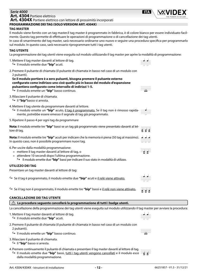
PROGRAMMAZIONE DEI TAG (SOLO VERSIONI ART. 4304X)TAG MASTERIl modulo viene fornito con un tag master.Il tag master è programmato in fabbrica, è di colore bianco per essere individuato facil-mente. Questo tag permette di effettuare le operazioni di programmazione o di cancellazione dei tag utenti.In caso di smarrimento del tag master, sarà necessario ordinarne uno nuovo e seguire una procedura specifica per programmarlo sul modulo. In questo caso, sarà necessario riprogrammare tutti i tag utenti.
TAG UTENTELa programmazione dei tag utenti viene eseguita sul modulo utilizzando il tag master per aprire la modalità di programmazione:
1. Mettere il tag master davanti al lettore di tag.↪ Il modulo emette due “bip” acuti. BIP BIP
2. Premere il pulsante di chiamata (il pulsante di chiamata in basso nel caso di un modulo con 2 pulsanti). Se il modulo portiere è a zero pulsanti, bisogna premere il pulsante esterno configurato come indirizzo uno cioè quello più in basso del modulo d’espansione pulsantiera configurato come intervallo di indirizzi 1-5.↪ Il modulo emette un “bip” basso continuo. BIIIIIIP
3. Rilasciare il pulsante di chiamata.↪ Il “bip”basso si arresta.
4. Mettere il tag utente da programmare davanti al lettore.↪ Il modulo emette un “bip” acuto, il tag è programmato. Se il tag non è rimosso rapida-
mente, potrebbe essere emesso il segnale di tag già programmato. BIP
5. Ripetere il passo 4 per ogni tag da programmare
Nota: il modulo emette tre “bip” bassi se un tag già programmato viene presentato davanti al let-tore di tag. BIP BIP BIP
Nota: Il modulo emette tre “bip” acuti per indicare che la memoria è piena (50 tag al massimo). In questo caso, non è possibile programmare nuovi tag. BIP BIP BIP
6. Per uscire dalla modalità programmazione: » mettere il tag master davanti al lettore di tag, o » attendere 10 secondi dopo l’ultima programmazione.↪ Il modulo emette due “bip” bassi per indicare il suo stato in modalità di utilizzo.
BIP BIP
UTILIZZO DEI TAGPresentare un tag master davanti al lettore di tag:
↪Se il tag è programmato, il modulo emette due “bip” acuti e il relè viene attivato.BIP BIP
↪Se il tag non è programmato, il modulo emette tre “bip” bassi e il relè non viene attivato.BIP BIP BIP
CANCELLAZIONE DEI TAG UTENTE
La procedura seguente cancellerà la programmazione di tutti i badge utenti.
La cancellazione della programmazione dei tag utenti viene eseguita sul modulo utilizzando il tag master per avviare la procedura:
1. Mettere il tag master davanti al lettore di tag.↪ Il modulo emette due “bip” acuti. BIP BIP
2. Premere il pulsante di chiamata (il pulsante di chiamata in basso nel caso di un modulo con 2 pulsanti).↪ Il modulo emette un “bip” basso continuo. BIIIIIIP
3. Rilasciare il pulsante di chiamata.↪ Il “bip” basso si arresta.
4. Premere continuamente il pulsante di chiamata e presentare il tag master davanti al lettore di tag.↪ Il modulo emette due “bip” bassi, tutti i tag utenti vengono cancellati e il modulo esce
dalla modalità programmazione.BIP BIP
Art. 4304 Portiere elettricoArt. 4304X Portiere elettrico con lettore di prossimità incorporati

66251857 - V1.5 - 31/12/21- 13 -
Serie 4000
Art. 4304/4304X - Istruzioni di installazione
RIPROGRAMMAZIONE DI UN TAG MASTERSe il tag master è stato smarrito o danneggiato, è possibile programmarne uno nuovo osservando la seguente procedura:
1. Togliere l’alimentazione.
2. Aprire la scatola del modulo.
3. Fare un ponte tra i morsetti PTE e GND o premere continuamente il pulsante “premere per uscire” se questo è collegato al modulo (vedere la Guida all’installazione del modulo).
ON
1 2 3 4 5 6 7 8
STEEL
MATTE
ALIHIGH BRASS
GUN METAL
4304X-14304X-0
4304X-2
EXPANSIONBUTTONS
NC
VAU
X+CCN
OG
ND
PTE
BU
SB
US
ABGN
D
RS485
4304-14304-0
4304-2
Made in Italy
4. Ripristinare l’alimentazione.↪ Il modulo emette un “bip” acuto. BIP
5. Togliere il ponte tra i morsetti PTE e GND o rilasciare il pulsante “premere per uscire”.↪ Il modulo emette un “bip” acuto. BIP
6. Presentare il nuovo tag master davanti al lettore di tag.↪ Il modulo emette due “bip” acuti, poi due “bip” bassi, il tag master è programmato, la
programmazione di tutti i tag utenti è cancellata e il modulo esce dalla modalità program-mazione.
BIP BIP
BIP BIP
7. Richiudere la scatola del modulo.
RIMOZIONE/INSERIMENTO DEL PORTA-CARTELLINO• Per evitare ammaccature della placca frontale, proteggere il lato che verrà in
contatto con la lama del cacciavite utilizzando una striscia di nastro isolante;• Inserire il cacciavite (lato piatto della lama) nell’apposita fessura del por-
ta cartellino come mostrato in Fig. 8;• Fare leva con il cacciavite come mostrato in Fig. 9 per rimuovere il por-
ta-cartellino (fare attenzione a non ammaccare la placca);• Modificare il cartellino e riporlo all’interno del porta-cartellino quindi
riposizionare lo stesso al suo posto inserendolo nel suo alloggiamento dal lato destro o sinistro e premendo il lato rimasto libero fino all’aggan-cio (compiendo un movimento contrario a quello fatto per estrarlo).
Fig. 8 Fig. 9
APPLICAZIONE GUARNIZIONE ADESIVAApplicare la guarnizione adesiva Y come mostrato in Fig. 10.
INSERIMENTO FERMI ANTI-EFFRAZIONEInserire i fermi anti-effrazione W come mostrato in Fig. 11.
Y
G
Fig. 10
W
Fig. 11
Art. 4304 Portiere elettricoArt. 4304X Portiere elettrico con lettore di prossimità incorporati

66251857 - V1.5 - 31/12/21- 14 -
Serie 4000
Art. 4304/4304X - Istruzioni di installazione
Art. 4304 Portiere elettricoArt. 4304X Portiere elettrico con lettore di prossimità incorporati
SEGNALI MORSETTERIA DI CONNESSIONEVERSIONI ART. 4304
BUSMorsetti di collegamento al BUS
BUS
PTE Ingresso di tipo attivo basso (quando attivo abilita il relé apri-porta)
GND MassaNO Relè apri-porta contatto normalmente aperto Max 12-24
Vac/dc 2AC Relè apri-porta contatto comune+C Uscita per attivazione serratura tramite scarica capacitiva
VAUX Ingresso 35 Vdc per alimentazione locale del posto esterno (l’alimentazione non è più fornita dal BUS)
NC Relè apri-porta contatto normalmente chiuso
Max 12-24Vac/dc 2A
VERSIONI ART. 4304XBUS
Morsetti di collegamento al BUSBUS
PTE Ingresso di tipo attivo basso (quando attivo abilita il relé apri-porta)
GND MassaNO Relè apri-porta contatto normalmente aperto Max 12-24
Vac/dc 2AC Relè apri-porta contatto comune+C Uscita per attivazione serratura tramite scarica capacitiva
VAUX Ingresso 35 Vdc per alimentazione locale del posto esterno (l’alimentazione non è più fornita dal BUS)
NC Relè apri-porta contatto normalmente chiuso
Max 12-24Vac/dc 2A
GND MassaB
Interfaccia seriale RS-485A
SPECIFICHE TECNICHEPulsanti di chiamata: Fino a 42Assorbimenti: Stand-by: 60+10mA per ogni 404x
In funzione: 80+10mA per ogni 404xPicco: 200mA
Tensione di lavoro: Fornita dalla linea BUSTemperatura di lavoro: -20 +60 °C
PULIZIA DELLA PLACCAUsare un panno morbido e pulito. Usare acqua tiepida o un de-tergente non aggressivo.Non usare:• prodotti abrasivi.• prodotti contenenti cloro.• prodotti per la pulizia dei metalli.

66251857 - V1.5 - 31/12/21- 15 -

66251857 - V1.5 - 31/12/21- 16 -

66251857 - V1.5 - 31/12/21- 17 -

66251857 - V1.5 - 31/12/21- 18 -

66251857 - V1.5 - 31/12/21- 19 -
DISPOSALIn accordance with the Legislative Decree no. 49 of 14 March 2014 “Implementation of the Directive 2012/19/EU on waste electrical and electronic equipment (WEEE)”.The crossed-out bin symbol on the equipment or on the packaging indicates that when the product reaches the end of its lifetime, it must be collected separately from mixed municipal waste. The user must, therefore, dispose of the equip-ment at the end of its lifetime in the suitable waste collection centres or bring it to the retailer during the purchase of a new equipment of equivalent type at the ratio of one-to-one. Furthermore, the user is allowed to dispose of the WEEEs of very small size (domestic appliances without any external dimension exceeding 25 cm (9.84 inches) for free to the retailers, without any purchase obligation. The correct waste disposal of the WEEEs contributes to their reuse, recycling and recovery and avoids potential negative effects on the environment and human health due to the possible presence of dangerous substances within them.
SMALTIMENTOAi sensi del Decreto Legislativo 14 marzo 2014, n° 49 “Attuazione della direttiva 2012/19/UE sui rifiuti di apparecchiature elettriche ed elettroniche (RAEE)”.Il simbolo del cassonetto barrato riportato sull’apparecchiatura o sulla sua confezione indica che il prodotto alla fine della propria vita utile deve essere raccolto separatamente dagli altri rifiuti urbani misti. L’utente dovrà, pertanto, conferire l’appa-recchiatura giunta a fine vita presso gli idonei centri di raccolta differenziata oppure riconsegnarla al rivenditore al momento dell’acquisto di una nuova apparecchiatura di tipo equivalente, in ragione di uno a uno. L’utente ha, inoltre, la possibilità di conferire gratuitamente presso i distributori, senza alcun obbligo di acquisto, per i RAEE di piccolissime dimensioni (per le apparecchiature di tipo domestico con nessuna dimensione esterna superiore a 25 cm).L’adeguata raccolta differenziata dei RAEE contribuisce al loro riutilizzo, riciclaggio e recupero ed evita potenziali effetti nega-tivi sull’ambiente e sulla salute umana dovuti alla eventuale presenza di sostanze pericolose al loro interno.
ÉLIMINATIONConformément au décret législatif n ° 49 du 14 mars 2014 relatif à l’ « Application de la directive 2012/19 / UE relative aux déchets d’équipements électriques et électroniques (DEEE) ».Le symbole de la poubelle barrée sur l’équipement ou sur son emballage indique que le produit en fin de vie utile doit être collecté séparément des autres déchets municipaux en mélange. L’utilisateur doit donc remettre l’équipement en fin de vie aux centres de collecte appropriés ou le restituer au revendeur lors de l’achat d’un nouveau type d’équipement équi-valent, dans le rapport de un à un. De plus, l’utilisateur a la possibilité de conférer gratuitement aux distributeurs, sans au-cune obligation d’achat, de très petits DEEE (pour les appareils ménagers sans dimensions extérieures supérieures à 25 cm). La collecte séparée adéquate des DEEE contribue à leur réutilisation, leur recyclage et leur valorisation et évite les éventuels effets négatifs sur l’environnement et la santé humaine en raison de la présence possible de substances dangereuses dans ceux-ci.
ELIMINACIÓNDe conformidad con el Decreto legislativo n. 49 de 14 de marzo 2014 “Aplicación de la Directiva 2012/19/UE relativa a resi-duos de aparatos eléctricos y electrónicos (RAEE)”.El símbolo del contenedor tachado indicado sobre los aparatos o sobre los embalajes señala que el producto al final de su vida útil debe ser recogido separadamente de otros residuos municipales mezclados. Por tanto, el usuario deberà conferir los aparatos al final de su vida útil en los apropriados centros de recogida selectiva o devolverlos al revendedor al momento de la compra de nuevos aparatos equivalentes, en una relación de uno a uno. Además, el usuario tiene la posibilidad de entre-gar sin cargo a los distribuidores, sin ninguna obligación de compra, los RAEEs muy pequeños (para electrodomésticos sin dimensiones externas superiores a 25 cm).La recogida selectiva apropriada de los RAEEs contribuye a su reutilización, reciclaje y valorización y evita potenciales impactos negativos sobre el medio ambiente y la salud humana debidos a la possible presencia de substancias peligrosas dentro de ellos.
ELIMINAÇÃODe acordo com o Decreto Legislativo n.º 49 de 14 de março de 2014 “Implementação da Diretiva 2012/19/UE relativa aos resíduos de equipamentos elétricos e eletrónicos (REEE)”.O símbolo do caixote do lixo riscado no equipamento ou na embalagem indica que quando o produto atinge o fim da sua vida útil, deve ser recolhido separadamente dos resíduos urbanos mistos. O utilizador deve, portanto, elimi-nar o equipamento no final da sua vida útil nos centros de recolha de resíduos adequados ou levá-lo ao vendedor durante a compra de um novo equipamento de tipo equivalente, na proporção de um para um. Além disso, o utili-zador pode eliminar gratuitamente os REEE de dimensões muito reduzidas aos vendedores, sem qualquer obrigação de compra.(só aparelhos domésticos sem qualquer dimensão externa que exceda 25 cm, ou seja 9,84 polegadas). A correta eliminação dos REEE contribui para a sua reutilização, reciclagem e recuperação e evita potenciais efeitos negativos sobre o ambiente e a saúde humana devido à possível presença de substâncias perigosas no seu interior.
VERWIJDERINGIn overeenstemming met het Wetsbesluit nr. 49 van 14 maart 2015 “Implementatie van de Richtlijn 2012/19/EU inzake afgedankte elektrische en elektronische apparaten (AEEA)”.Het doorgekruiste vuilnisbaksymbool op het apparaat of de verpakking geeft aan dat het product aan het einde van zijn levensduur niet samen met het gewone huisvuil weggegooid mag worden. De gebruiker moet het apparaat aan het einde van zijn levensduur inleveren bij een gepast inzamelpunt of de winkel waar hij een nieuw apparaat van een gelijksoortig type zal kopen. De gebruiker kan tevens AEEA’s van een zeer klein formaat (huishoudapparaten met een buitenafmeting kleiner dan 25 cm (9,84 inch) gratis en zonder enige aankoopverplichting bij handelaars inleveren. Een juiste verwijdering van AEEA’s draagt bij tot hergebruik, recycling en terugwinning, en voorkomt potentiële negatieve effecten op het milieu en de menselijke gezondheid door de mogelijke aanwezigheid van gevaarlijke stoffen.

MANUFACTURERFABBRICANTEFABRICANTFABRICANTEFABRIKANTFABRICANTE
كة المصنعة ال�ش
VIDEX ELECTRONICS S.P.A.Via del Lavoro, 163846 Monte Giberto (FM) ItalyTel (+39) 0734 631669Fax (+39) 0734 632475www.videx.it - [email protected]
CUSTOMER SUPPORTSUPPORTO CLIENTISUPPORTS CLIENTSATENCIÓN AL CLIENTEKLANTENDIENSTAPOIO AO CLIENTE
خدمة العملاء
VIDEX ELECTRONICS S.P.A.www.videx.it - [email protected]: +39 0734-631669Fax: +39 0734-632475
UK Customers only:VIDEX SECURITY LTDwww.videxuk.comTech Line: 0191 224 3174Fax: 0191 224 1559
Main UK office:VIDEX SECURITY LTD1 Osprey Trinity ParkTrinity WayLONDON E4 8TDPhone: (+44) 0370 300 1240Fax: (+44) 020 8523 [email protected]
Northern UK office:VIDEX SECURITY LTDUnit 4-7Chillingham Industrial EstateChapman StreetNEWCASTLE UPON TYNE - NE6 2XXTech Line: (+44) 0191 224 3174Phone: (+44) 0370 300 1240Fax: (+44) 0191 224 1559
Greece office:VIDEX HELLAS Electronics48 Filolaou Str.11633 ATHENSPhone: (+30) 210 7521028 (+30) 210 7521998 Fax: (+30) 210 [email protected]
Danish office:VIDEX DANMARKHammershusgade 15DK-2100 COPENHAGENPhone: (+45) 39 29 80 00Fax: (+45) 39 27 77 [email protected]
Benelux office:NESTOR COMPANY NVE3 laan, 93B-9800 DeinzePhone: (+32) 9 380 40 20Fax: (+32) 9 380 40 [email protected]
Dutch office:NESTOR COMPANY BVBusiness Center Twente (BCT)Grotestraat, 64NL-7622 GM [email protected]
The product is CE marked demonstrating its conformity and is for distribution with-in all member states of the EU with no restrictions. This product follows the provi-sions of the European Directives 2014/30/EU (EMC); 2014/35/EU (LVD); 2011/65/EU (RoHS): CE marking 93/68/EEC.
Il prodotto è marchiato CE a dimostrazione della sua conformità e può essere distri-buito liberamente all’interno dei paesi membri dell’Unione Europea UE.Questo prodotto è conforme alle direttive Europee: 2014/30/UE (EMC); 2014/35/UE (LVD); 2011/65/UE (RoHS): marcatura CE 93/68/EEC.
Le produit est marqué CE à preuve de sa conformité et peut être distribué librement à l’intérieur des pays membres de l’union européenne EU.Ce produit est conforme aux directives européennes 2014/30/EU (EMC) ; 2014/35/EU (LVD) ; 2011/65/EU (RoHS): marquage CE 93/68/EEC.
El producto lleva la marca CE que demuestra su conformidad y puede ser distribuido en todos los estados miembros de la unión europea UE.Este producto cumple con las Directivas Europeas 2014/30/EU (EMC); 2014/35/EU (LVD); 2011/65/EU (RoHS): marca CE 93/68/EEC.
Het product heeft de CE-markering om de conformiteit ervan aan te tonen en is be-stemd voor distributie binnen de lidstaten van de EU zonder beperkingen. Dit pro-duct volgt de bepalingen van de Europese Richtlijnen 2014/30/EU (EMC); 2014/35/EU (LVD); 2011/65/EU (RoHS): CE-markering 93/68/EEG.
O produto tem a marca CE que demonstra a sua conformidade e destina-se a dis-tribuição em todos os estados membros da UE, sem restrições. Este produto segue as disposições das Diretivas Europeias 2014/30/UE (EMC); 2014/35/UE (LVD); 2011/65/UE (RoHS): marcação CE 93/68/CEE.
ظهار توافقه مع المواصفات ذات الصلة وإمكانية ي CE لإ يحمل المنتج علامة التوافق الأورو�بي هذا المنتج جميع متطلبات التوجيهات ي بدون أية قيود. يل�ب ة دول التحاد الأورو�ب ي كاف
توزيعه �فالأوروبية EU )LVD/35/2014 ;)EU )EMC/30/2014(; EU/65/2011 ــ )RoHS(: علامة المطابقة
.EEC/68/93 CE للمواصفات الأوروبية


![[4304]101sangamnercollege.edu.in/pdf/arts/previous-exam-question... · 2018-08-14 · Total No. of Questions—4] [Total No. of Printed Pages—4 Seat No. [4304]101 M.A. (Part I)](https://img.pdfslide.us/doc/110x75/5e822deb09298a24ff2febaf/4304-2018-08-14-total-no-of-questionsa4-total-no-of-printed-pagesa4.jpg)