Embed Size (px)
Citation preview

Ver.1.1Ver.1.1Ver.1.1Ver.1.1
400 VAC 550 W- 30 kW
Ver. 2

Contents
Lineup .............................................................p. 5
Features .........................................................p. 7
List of Compatible Servo Ampli�ers
and Servo Motors ..................................... p. 12
Standard Model Number List ..... p. 13
Servo ampli�ers .................................. p. 19
R 3E Model Analog/Pulse Input type .....p. 20
EtherCAT Interface type .....p. 34
Safety Interface type ...........p. 44
Servo motors ..........................................p. 49
Speci�cations - Servo Ampli�ers +
R2 Servo Motors (Medium Inertia) ...p. 50
R1 Servo Motors (Low Inertia) ..........p. 56
Servo Motor Dimensions...............p. 60
Options........................................................p. 67
Selection Guide.....................................p. 85
Motor Protection Rating .................p. 88
Safety Precautions..............................p. 89
Servo amplifier
25, 50, 100, 150, 300 A
Servo motor
100 mm sq., 130 mm sq., 180 mm sq.,
220 mm sq., 275 mm sq.
550 W to 30 kW
Amplifier capacity
Flange size
Rated output
Output capacity 550 W to 30 kWInput voltage 400 VAC

Application ExamplesIts high-precision and accurate positioning features allow it to be used in a wide range of applications.・ Injection molding machines, machine tools, machining centers, semiconductor related equipment, water jet
cutters, laser processing machines, etc.
Machine toolsInjection molding machines
Servo system SANMOTION R
Servo system SANMOTION R
・ What is a servo system?A servo system has an encoder (rotation detector) mounted on the servo motor and provides highly-reliable precise operation by giving feedback to commands from the servo amplifier. It can be used with confidence in applications that require high-speed and large-capacity operations.
The products featured in this catalog are designed to operate with a 400 VAC class main circuit power supply.We also have servo systems for 100 to 200 VAC and 48 VDC inputs available. Refer to our website and catalogs for details.
Controller
System Configurations
SANMOTION R3E Model
SANMOTION R3E Model
Analog/Pulse
Safety
Safety
EtherCAT
High Performance AC Servo Systems
The SANMOTION R series servo systems contribute to the evolution of your devices with a rich product lineup of high-precision servo amplifiers and servo motors.These high-precision and highly reliable systems offer a wide range of products from small to large capacity servo systems.
Servo motor (Rotary motor)
Servo motor (Rotary motor)Servo amplifier
Servo amplifier
SANMOTION CEtherCAT Interface type
Touch panel Controller
4

Servo Amplifier
SANMOTION R 3E Model
Analog/Pulse Input typeMore evolved AC servo amplifiers that provide improved basic performance including high responsiveness, and are more eco-efficient and easier to use.
Lineup: 25, 50, 100, 150, 300 A →p. 20
■ Functional safety specifications Models that facilitate easy integration of safety functions in devices to comply with functional safety are available.
Servo amplifier typeModel no.
Functional safety specificationsAnalog/Pulse EtherCAT
SANMOTION R3E Model
RS3C□□A□□□0 - Models not conforming to the functional safety.
RS3C□□A□□□2 RS3C□□A2H□4These models have the Safe Torque Off function.
IEC/EN 61800-5-2:2016, STO (Safe Torque Off)
SANMOTION R3E ModelSafety→ p. 44
RS3C□□A□□□C RS3C□□A2H□E
This model has integrated extended safety functions in addition to Safe Torque Off function.Maintenance work can be performed without shutting off the power to the device. System restarting after maintenance work has also been made easy.
IEC/EN 61800-5-2:2016, STO (Safe Torque Off), SS1 (Safe Stop 1), SS2 (Safe Stop 2), SOS (Safe Operating Stop), SLS (Safely-Limited Speed), SBC (Safe Brake Control), and SSM (Safe Speed Monitor)
EtherCAT Interface typeWith a 62.5 µs minimum communication cycle, the high-speed EtherCAT fieldbus subdivides position commands, realizing smoother operation of devices.It can be used together with our controller “SANMOTION C EtherCAT Interface type”.
Lineup: 25, 50, 100, 150, 300 A →p. 34
Lineup
5

Servo Amplifier
Servo Motor (Rotary Motor)Rotary servo motors with a wide range of products.
Motor type Flange size, features
R2 Servo MotorMedium inertiaLow ripple
100 mm sq., 130 mm sq., 180 mm sq., 220 mm sq., 275 mm sq.
Medium inertia servo motors with a wide range of
size variation ideal for positioning applications.
R1 Servo MotorLow inertiaHigh power rate
100 mm sq., 130 mm sq., 180 mm sq., 220 mm sq.
Low inertia servo motors that feature high-acceleration
drive and high torque even at high rotational speed.
Ideal for injection molding machines and general
industrial machines.
Our standard servo amplifiers conform to the following safety standards: UL, cUL, and EN standards,
and the KC Mark. Our servo motors conform to the following safety standards: UL, cUL, and EN
standards. In addition, all model numbers manufactured after October 2012 in this catalog conform
with the acceptable values of specific hazardous substances (cadmium, lead, mercury, hexavalent
chrome, PBB, and PBDE) in Appendix II of EU RoHS directive (2011/65/EU).
Conformance to Safety Standards
Safe Torque Off model,Safety model
Lineup
6

Evolved
High Performance AC Servo Systems
The 3rd generation of SANMOTION R servo amplifier series “3E Model” features evolved performance with high responsiveness and are more eco-efficient and easier to use.It contributes to improving the device performance.
Built-in safety functions
The series product lineup includes Safe Torque Off (STO) function models*1 and Safety models*2 that offer even wider range of safety functions. Safety models feature monitoring of position and speed of devices as well as safe operation stop so that workers nearby can concentrate on their work with confidence. With these safety functions, motors can be stopped without shutting down the amplifier power, shortening the device reboot time. These products are suitable for devices that require high levels of safety.*1 Safe Torque Off (STO) is a safety function defined in IEC/EN 61800-5-2:2016.*2 In addition to *1, SS1 (Safe Stop 1), SS2 (Safe Stop 2), SOS (Safe Operating Stop), SLS (Safely-Limited Speed), SBC (Safe Brake Control), and SSM (Safe Speed Monitor)
Cycle time can be shortened by high-speed positioning control
The 3E Model has a speed frequency response of 2.2 kHz, approximately twice that of our conventional product. Additionally, the posi-tion settling time has been shortened to 1/3 of the original time. A function for switching the trajectory control and the positioning control in real time has been incorporated, signifi-cantly reducing the cycle time of the device.
In-position range
Settling time: 1/3 of current model
Conventional model
Position command frequency
0 [Pulse]
0 [Pulse/s]
Position deviation
Disturbance
After adaptation
Starts when vibrations occur
Increased accuracy
Adaptive notch �lter
High-gain control
Vibration suppression by adaptive notch �lter
Speed
Conventional model
Conventional model
The 3E Model is equipped with a gain increase function, a function for suppressing microvi-brations at settling time, an adaptive notch filter for suppressing mechanical resonance, and a feed-forward vibration control function. The improved 5th-order notch filter realizes accurate shaft feeding for machine tools, sig-nificantly enhancing the processing quality.
Improved control accuracy
7

Eco-efficient
Easy to use
Easy troubleshootingEasy servo tuning
With the setup software, the 3E Model amplifiers offer a variety of servo tuning support functions such as the automatic optimal tuning mode selection according to equipment and load conditions, basic tuning mode for 2-parameter adjustment, and application tuning mode for adjustment by purpose. This greatly shortens the time required for servo tuning.
With a 1 ms time stamp and a drive recorder function to record motor and amplifier operating status, details of abnormal state occurrences such as alarms can be accurately checked even at a later time, facilitating troubleshooting.
Holding brake control function incorporated as standard
The holding brake function has been incorporated into servo amplifiers as standard, which eliminates the need to newly establish a brake control circuit. This reduces wiring and costs.
This only applies to 24 VDC brakes.Note: The holding brake holds the motor in position when the power is off, preventing loads from falling.
CND
24 VDCpower supply
Holding brake
Servo ampli�erCNE
B+
B-Relay
Switchpowersupply
Easy startup
“SANMOTION MOTOR SETUP SOFTWARE” (see p. 127) displays the parameters required for operation in an easy-to-understand manner in order to enable fast and easy equipment startup. The 3E Model has a virtual motor operation function to simulate operation of the motor and amplifier without moving the machine, and a jog function for testing the motor and amplifier connection, without the need to connect to a host device.
Minimally required parameters can be set prior to the start of an operation, which are lumped together by categories, to shorten time for startup.
Reduced power consumption Power consumption management
Axis
X
Y
Z
Total
Unit
kWh
kWh
kWh
kWh
Power consumption
0.41
0.75
0.21
1.37
Our new servo amplifiers consume less power; a maximum of 15% reduction in power consumption and a maximum of 29% reduction in standby power consumption have been achieved.
Power consumption of the device can be managed by the monitor-ing function. The servo amplifier calculates power consumption based on the motor current, and displays it on the setup software or digital operator.
Powerconsumption
REDUCED
Note: Compared with a conventional RS1C02A model.
8
Features

Position/speed control Motor/machine model
Position/speed control Motor/machine
Model control system
Feedback control system
Position command
Tuning start Detected velocity value
Velocity command value
Model-based following control Auto-tuning
Model-based following control enables an improved target value response, enhanced disturbance sup-pression, and greater robustness.
The servo amplifier automatically optimizes servo gain and filter frequency in real time.
Position deviation during stop
With vibration suppression controlWithout vibration suppression control
100 ms/divWithout vibration
suppression controlWith vibration
suppression control
Position deviation
Position command
20 ms/div
Feed-forward vibration suppression control Command following control
With feed-forward vibration suppression control, vi-brations at the end effector and base of a machine can be suppressed through simple tuning proce-dures. Vibration control frequencies are selectable.
Newly-employed position and velocity controller has improved the tracking capability to the position com-mands. Position deviation ≈ 0 has been achieved.
5-digit LED, built-in operator
The built-in digital operator allows you to change pa-rameters and monitor amplifier status and alarm traces.
Flat
Torquecontrol
START
GOAL
Positionor
Velocity control
Ascen
ding
All-in-one control
Configurable parameters allow switching between control modes for torque, position or velocity.
9
Features

Maximum 15 axes
USB hub
Load
Multiaxial monitor function Dual position feedback fully-closed loop control
The setup software allows up to 15 axes—that is, 15 sets of a servo motor and a servo amplifier—to be monitored.
Dual position feedback fully-closed loop control is possible by using information from two encoders: a linear encoder mounted on the device (load) and a high resolution motor-mounted encoder.Even when there is high motor shaft torsion from the load, servo gain can be improved and high response achieved.
EtherCAT is a 100 Mbps high-speed fieldbus system.This contributes to reducing equipment cycle time. This highly versatile EtherCAT is compatible with Ethernet, which makes it possible to build a system that co-exists with various devices. The servo amplifier firmware can be updated via EtherCAT network. Also, the EtherCAT conformance test certificate from a trusted third party has been acquired.
Downsized servo motors
Our R2 series servo motors have 22% reduced motor length while achieving high torque and high overall performance compared with our conventional mod-el.*
* Comparing the R2CA18350 model with a conventional Q2CA18350 model.
22% reductionEtherCAT® is a registered trademark and patented technology, licensed by Beckhoff Automation GmbH, Germany.
EtherCAT Interface type
* Except for shaft through-hole and cable ends. Use with a waterproof cannon plug connector. This motor meets the standardized water-proof test conditions. It cannot be used in environments exceeding IP65 or IP67, such as where it is subject to submersion in water for prolonged periods.
* Compared with a conventional SANMOTION Q model.
Cogging torque has been reduced in comparison with our conventional products, achieving smoother movement.
Comparison of cogging torque waveforms
R Motor
Current model
(Waveform image for reference)
Low cogging torque
Water Dust
Our servo motors are highly resistant to water and dust ingress with an IP65 rating, ensuring normal op-eration even in severe environments.IP67 is available as an option.
Waterproof and dustproof
10
Features

No need to worry about battery life
and battery exporting procedures.
Absolute encoder
Type (Encoder model number in parentheses) Classification
Resolution during single
rotation
Total number of rotations
during multiple rotations
Baud rateAbsolute angular
accuracy
Battery-less absolute encoder(Model No. HA035)This is a high-precision, battery-less, optical multi-turn encoder.Because there is no need to replace batteries, the encoder is maintenance free.
Compatible servo amplifiers: R 3E Model
Standard131072 (17 bit)
65536(16 bit)
2.5 Mbps
Approx. 0.167°
Options
1048576 (20 bit)
4.0 Mbps
Under 0.0167°
8388608 (23 bit)
Single-turn absolute encoder(Model No. PA035S)This is a thin, optical single-turn encoder.It achieves wire saving particularly for systems that currently use incremental encoders, and helps downsize the systems.
Standard131072 (17 bit)
-
2.5 Mbps
Approx. 0.167°
Options1048576 (20 bit)
4.0 Mbps
Approx. 0.167°
Battery-backup absolute encoder(Model No. PA035C)This is a thin, battery-backed, optical multi-turn encoder.Because the length of the motor can be shortened, it is ideal for devices with limited motor installation space.It requires an optional battery.
Options
131072 (17 bit)
65536(16 bit)
2.5 Mbps
Approx. 0.167°
1048576 (20 bit)
4.0 Mbps
Approx. 0.167°
Battery-less absolute resolver encoder(Model No. RA035C)This is a resolver method battery-less multi-turn encoder.This is an environmentally durable resolver encoder.
Options131072 (17 bit)
65536(16 bit)
2.5 Mbps
Approx. 0.167°
4.0 Mbps
Approx. 0.167°
Incremental encoder
Type (Encoder model number in parentheses) ClassificationPulse/
rotation
Wire-saving incremental encoder(Model No. PP031H)This is an incremental encoder with A, B, and Z-phase outputs that can easily be combined with a host controller.
OptionsUp to
10000 P/R
Highly precise battery-less absolute encoder
This high-precision battery-less absolute encoder Model No. HA035 comes equipped with our servo motors as standard.Optional higher precision encoders with a resolution of up to 8,388,608 (23-bit) and angular accuracy of up to 0.0167° (1 arcmin) are available.
We offer a variety of optional encoders to meet various encoder needs.Refer to the following table.
11
Features

Standard specification ●S …Output shaft: Straight, Oil seal: None, Connecting method: Cannon plug
●K …Output shaft: With key, Oil seal: Yes, Connecting method: Cannon plug (15 kW or lower), Terminal block (20 kW or higher)
Servo motor Servo amplifierMotor type Rated
outputFlange size Model name Standard
specificationPage
R 3E ModelAnalog/Pulse Input typep. 20
EtherCAT Interface typep. 34
Specifications Dimensions
R2Servo motor
400 V systemMedium inertia
550 W 130 mm sp. R2CA13050D ●K p. 50 p. 60 RS3C02□□《25 A》
750 W 100 mm sp. R2CA10075F ●S p. 50 p. 60 RS3C02□□《25 A》
1.0 kW 100 mm sp. R2CA10100F ●S p. 50 p. 60 RS3C05□□《50 A》
1.2 kW130 mm sp. R2CA13120R ●K p. 50 p. 60 RS3C02□□《25 A》130 mm sp. R2CA13120F ●K p. 51 p. 60 RS3C05□□《50 A》
1.8 kW130 mm sp. R2CA13180H ●K p. 51 p. 60 RS3C02□□《25 A》130 mm sp. R2CA13180D ●K p. 51 p. 60 RS3C05□□《50 A》
2.0 kW130 mm sp. R2CA13200L ●K p. 52 p. 61 RS3C02□□《25 A》130 mm sp. R2CA13200H ●K p. 52 p. 61 RS3C05□□《50 A》
3.5 kW180 mm sp. R2CA18350L ●K p. 52 p. 61 RS3C05□□《50 A》180 mm sp. R2CA18350D ●K p. 53 p. 61 RS3C10□□《100 A》
4.5 kW 180 mm sp. R2CA18450H ●K p. 53 p. 61 RS3C10□□《100 A》
5.5 kW180 mm sp. R2CA18550R ●K p. 53 p. 61 RS3C10□□《100 A》180 mm sp. R2CA18550H ●K p. 54 p. 61 RS3C15□□《150 A》
7.5 kW 180 mm sp. R2CA18750H ●K p. 54 p. 62 RS3C15□□《150 A》
11 kW 220 mm sp. R2CA2211KB ●K p. 54 p. 62 RS3C15□□《150 A》
15 kW 220 mm sp. R2CA2215KV ●K p. 55 p. 62 RS3C15□□《150 A》
20 kW 220 mm sp. R2CA2220KV ●K p. 55 p. 63 RS3C30□□《300 A》
30 kW 275 mm sp. R2CA2830KV ●K p. 55 p. 63 RS3C30□□《300 A》
R1Servo motor
400 V systemLow inertia
1.5 kW 100 mm sp. R1CA10150V ●K p. 56 p. 64 RS3C02□□《25 A》
2.0 kW 100 mm sp. R1CA10200V ●K p. 56 p. 64 RS3C05□□《50 A》
3.0 kW 130 mm sp. R1CA13300V ●K p. 57 p. 64 RS3C05□□《50 A》
5.5 kW 180 mm sp. R1CA18550H ●K p. 57 p. 65 RS3C15□□《150 A》
7.5 kW 180 mm sp. R1CA18750L ●K p. 58 p. 65 RS3C15□□《150 A》
11 kW 180 mm sp. R1CA1811KR ●K p. 58 p. 65 RS3C15□□《150 A》
15 kW 180 mm sp. R1CA1815KB ●K p. 59 p. 65 RS3C15□□《150 A》
21 kW 220 mm sp. R1CA2220KV ●K p. 59 p. 65 RS3C30□□《300 A》
List of Compatible Servo Amplifiers and Servo Motors
List of Compatible
Servo Amplifiers
and Servo Motors
12
List of Compatible Servo Amplifiers and Servo Motors

Standard Model Number List For specifications on other models, contact us for details.
Input voltage 400 VAC List of Compatible Servo Amplifiers and Servo Motors
List of Compatible
Servo Amplifiers
and Servo Motors
Servo Amplifier R 3E Model Analog/Pulse Input typeMain circuit
power supplyControl circuit power supply
Encoder type
General-purpose output
Internal regenerative
resistor
Safe Torque Off function*1 Safety*2 Amplifier
capacity Model no.Page
Specifications Dimensions
400 VAC system380 to 480 VAC
3-phase24 VDC
Absoluteencoder
Sink (NPN)
Yes
No No
25 A RS3C02A0AA0 p. 24 p. 26
50 A RS3C05A0AA0 p. 24 p. 26
100 A RS3C10A0AA0 p. 24 p. 26
No150 A RS3C15A0AL0 p. 24 p. 27
300 A RS3C30A0AM0 p. 24 p. 27
Yes Yes(without delay
circuit)No
25 A RS3C02A0AA2 p. 24 p. 26
50 A RS3C05A0AA2 p. 24 p. 26
100 A RS3C10A0AA2 p. 24 p. 26
No150 A RS3C15A0AL2 p. 24 p. 27
300 A RS3C30A0AM2 p. 24 p. 27
Yes Yes(without delay
circuit)Yes
25 A RS3C02A0AAC pp. 24, 44 p. 46
50 A RS3C05A0AAC pp. 24, 44 p. 46
100 A RS3C10A0AAC pp. 24, 44 p. 46
No150 A RS3C15A0ALC pp. 24, 44 p. 46
300 A RS3C30A0AMC pp. 24, 44 p. 46
Source (PNP)
Yes
No No
25 A RS3C02A0BA0 p. 24 p. 26
50 A RS3C05A0BA0 p. 24 p. 26
100 A RS3C10A0BA0 p. 24 p. 26
No150 A RS3C15A0BL0 p. 24 p. 27
300 A RS3C30A0BM0 p. 24 p. 27
Yes Yes(without delay
circuit)No
25 A RS3C02A0BA2 p. 24 p. 26
50 A RS3C05A0BA2 p. 24 p. 26
100 A RS3C10A0BA2 p. 24 p. 26
No150 A RS3C15A0BL2 p. 24 p. 27
300 A RS3C30A0BM2 p. 24 p. 27
Yes Yes(without delay
circuit)Yes
25 A RS3C02A0BAC pp. 24, 44 p. 46
50 A RS3C05A0BAC pp. 24, 44 p. 46
100 A RS3C10A0BAC pp. 24, 44 p. 46
No150 A RS3C15A0BLC pp. 24, 44 p. 46
300 A RS3C30A0BMC pp. 24, 44 p. 46
Servo Amplifier R 3E Model EtherCAT Interface typeMain circuit
power supplyControl circuit power supply
Encoder type
General-purpose output
Internal regenerative
resistor
Safe Torque Off function*1 Safety*2 Amplifier
capacity Model no.Page
Specifications Dimensions
400 VAC system380 to 480 VAC
3-phase24 VDC
Absoluteencoder
Photorelay
output
Yes Yes(without delay
circuit)No
25 A RS3C02A2HA4 p. 38 p. 40
50 A RS3C05A2HA4 p. 38 p. 40
100 A RS3C10A2HA4 p. 38 p. 40
No150 A RS3C15A2HL4 p. 38 p. 41
300 A RS3C30A2HM4 p. 38 p. 41
Yes Yes(without delay
circuit)Yes
25 A RS3C02A2HAE pp. 38, 44 p. 46
50 A RS3C05A2HAE pp. 38, 44 p. 46
100 A RS3C10A2HAE pp. 38, 44 p. 46
No150 A RS3C15A2HLE pp. 38, 44 p. 46
300 A RS3C30A2HME pp. 38, 44 p. 46
Our standard servo amplifiers conform to UL, c-UL, and EN standards as well as KC mark.*1 Safe Torque Off (STO) is a safety function defined in IEC/EN 61800-5-2:2016.*2 In addition to *1, SS1 (Safe Stop 1), SS2 (Safe Stop 2), SOS (Safe Operating Stop), SLS (Safely-Limited Speed), SBC (Safe Brake Control), and SSM (Safe
Speed Monitor) → p.44
13
Standard M
odel N
umber List

Standard Model Number List For specifications on other models, contact us for details.
Input voltage 400 VAC
Ratedoutput
Motor flangesize
Protectioncode
Holdingbrake
(24 DCV)
Standardspecification
CE and UL
approved
Model no. Page
Battery-lessabsolute encoder
(Model No. HA035)
Single-turn absolute encoder
(Model No. PA035S)Specifications Dimensions
550 W 130 mm sp. IP65No ●K Yes R2CA13050DXR00M R2CA13050DXH00M p. 50 p. 60
Yes ●K Yes R2CA13050DCR00M R2CA13050DCH00M p. 50 p. 60
750 W 100 mm sp. IP65No ●S Yes R2CA10075FXR03M R2CA10075FXH03M p. 50 p. 60
Yes ●S Yes R2CA10075FCR03M R2CA10075FCH03M p. 50 p. 60
1.0 kW 100 mm sp. IP65No ●S Yes R2CA10100FXR03M R2CA10100FXH03M p. 50 p. 60
Yes ●S Yes R2CA10100FCR03M R2CA10100FCH03M p. 50 p. 60
1.2 kW 130 mm sp. IP65
No ●K Yes R2CA13120RXR00M R2CA13120RXH00M p. 50 p. 60
Yes ●K Yes R2CA13120RCR00M R2CA13120RCH00M p. 50 p. 60
No ●K Yes R2CA13120FXR00M R2CA13120FXH00M p. 51 p. 60
Yes ●K Yes R2CA13120FCR00M R2CA13120FCH00M p. 51 p. 60
1.8 kW 130 mm sp. IP65
No ●K Yes R2CA13180HXR00M R2CA13180HXH00M p. 51 p. 60
Yes ●K Yes R2CA13180HCR00M R2CA13180HCH00M p. 51 p. 60
No ●K Yes R2CA13180DXR00M R2CA13180DXH00M p. 51 p. 60
Yes ●K Yes R2CA13180DCR00M R2CA13180DCH00M p. 51 p. 60
2.0 kW 130 mm sp. IP65
No ●K Yes R2CA13200LXR00M R2CA13200LXH00M p. 52 p. 61
Yes ●K Yes R2CA13200LCR00M R2CA13200LCH00M p. 52 p. 61
No ●K Yes R2CA13200HXR00M R2CA13200HXH00M p. 52 p. 61
Yes ●K Yes R2CA13200HCR00M R2CA13200HCH00M p. 52 p. 61
3.5 kW 180 mm sp. IP65
No ●K Yes R2CA18350LXR00M R2CA18350LXH00M p. 52 p. 61
Yes ●K Yes R2CA18350LCR00M R2CA18350LCH00M p. 52 p. 61
No ●K Yes R2CA18350DXR00M R2CA18350DXH00M p. 53 p. 61
Yes ●K Yes R2CA18350DCR00M R2CA18350DCH00M p. 53 p. 61
4.5 kW 180 mm sp. IP65No ●K Yes R2CA18450HXR00M R2CA18450HXH00M p. 53 p. 61
Yes ●K Yes R2CA18450HCR00M R2CA18450HCH00M p. 53 p. 61
5.5 kW 180 mm sp. IP65
No ●K Yes R2CA18550RXR00M R2CA18550RXH00M p. 53 p. 61
Yes ●K Yes R2CA18550RCR00M R2CA18550RCH00M p. 53 p. 61
No ●K Yes R2CA18550HXR00M R2CA18550HXH00M p. 54 p. 61
Yes ●K Yes R2CA18550HCR00M R2CA18550HCH00M p. 54 p. 61
7.5 kW 180 mm sp. IP65No ●K Yes R2CA18750HXR00M R2CA18750HXH00M p. 54 p. 62
Yes ●K Yes R2CA18750HCR00M R2CA18750HCH00M p. 54 p. 62
11 kW 220 mm sp. IP65No ●K Yes R2CA2211KBXR00M R2CA2211KBXH00M p. 54 p. 62
Yes ●K Yes R2CA2211KBCR00M R2CA2211KBCH00M p. 54 p. 62
15 kW 220 mm sp. IP65No ●K Yes R2CA2215KVXR00M R2CA2215KVXH00M p. 55 p. 62
Yes ●K Yes R2CA2215KVCR00M R2CA2215KVCH00M p. 55 p. 62
20 kW 220 mm sp. IP65No ●K No R2CA2220KVXR00 R2CA2220KVXH00 p. 55 p. 63
Yes ●K No R2CA2220KVCR00 R2CA2220KVCH00 p. 55 p. 63
30 kW 275 mm sp. IP65No ●K No R2CA2830KVXR00 R2CA2830KVXH00 p. 55 p. 63
Yes ●K No R2CA2830KVCR00 R2CA2830KVCH00 p. 55 p. 63
R2 Servo MotorStandard specification ●S …Output shaft: Straight, Oil seal: None, Connecting method: Cannon plug
●K …Output shaft: With key, Oil seal: Yes, Connecting method: Cannon plug
14
Standard Model Number List

Standard Model Number List For specifications on other models, contact us for details.
Input voltage 400 VAC
Ratedoutput
Motor flangesize
Protectioncode
Holdingbrake
(24 DCV)
Standardspecification
CE and ULapproved
Model no. Page
Battery-lessabsolute encoder
(Model No. HA035)
Single-turn absolute encoder
(Model No. PA035S)Specifications Dimensions
1.5 kW 100 mm sp. IP65No ●K Yes R1CA10150VXR00M R1CA10150VXH00M p. 56 p. 64
Yes ●K Yes R1CA10150VCR00M R1CA10150VCH00M p. 56 p. 64
2.0 kW 100 mm sp. IP65No ●K Yes R1CA10200VXR00M R1CA10200VXH00M p. 56 p. 64
Yes ●K Yes R1CA10200VCR00M R1CA10200VCH00M p. 56 p. 64
3.0 kW 130 mm sp. IP65No ●K Yes R1CA13300VXR00M R1CA13300VXH00M p. 57 p. 64
Yes ●K Yes R1CA13300VCR00M R1CA13300VCH00M p. 57 p. 64
5.5 kW 180 mm sp. IP65No ●K Yes R1CA18550HXR00M R1CA18550HXH00M p. 57 p. 65
Yes ●K Yes R1CA18550HCR00M R1CA18550HCH00M p. 57 p. 65
7.5 kW 180 mm sp. IP65No ●K Yes R1CA18750LXR00M R1CA18750LXH00M p. 58 p. 65
Yes ●K Yes R1CA18750LCR00M R1CA18750LCH00M p. 58 p. 65
11 kW 180 mm sp. IP65No ●K Yes R1CA1811KRXR00M R1CA1811KRXH00M p. 58 p. 65
Yes ●K Yes R1CA1811KRCR00M R1CA1811KRCH00M p. 58 p. 65
15 kW 180 mm sp. IP65No ●K Yes R1CA1815KBXR00M R1CA1815KBXH00M p. 59 p. 65
Yes ●K Yes R1CA1815KBCR00M R1CA1815KBCH00M p. 59 p. 65
21 kW 220 mm sp. IP65 No ●K No R1CA2220KVXR00 R1CA2220KVXH00 p. 59 p. 65
R1 Servo MotorStandard specification ●S …Output shaft: Straight, Oil seal: None, Connecting method: Cannon plug
●K …Output shaft: With key, Oil seal: Yes, Connecting method: Cannon plug
15
Standard M
odel N
umber List

Standard Model Number List For specifications on other models, contact us for details.
Input voltage 400 VAC Option
R 3E Model Analog/Pulse Input type
Model no. Category Remarks Page
AL-00385594
Servo amplifier connector, individual item
For controller connection (CN1) pp. 70, 71
AL-00632607 For encoder connection (EN1, EN2)Note that this is not a set of two connectors, but a single connector.
pp. 70, 71
AL-00718251-01 For safety function connection [for short-circuiting (CN4)] pp. 70, 71
AL-00723290
Servo amplifier connector set
(For non-STO models)
CN1, EN1 (standard) pp. 70, 71
AL-00966991 CN1, EN1, CNE with connector tool (standard) p. 70
AL-00966993 CN1, EN1, EN2 (for fully closed-loop systems) pp. 70, 71
AL-00966995 CN1, EN1, EN2, CNE with connector tool (for fully closed-loop systems) p. 70
AL-00723159
Servo amplifier connector set
(For STO models)
CN1, EN1, CN4 (standard) pp. 70, 71
AL-00967013 CN1, EN1,CN4, CNE with connector tool (standard) p. 70
AL-00967015 CN1, EN1, EN2, CN4 (for fully closed-loop systems) pp. 70, 71
AL-00967017 CN1, EN1, EN2, CN4, CNE with connector tool (for fully closed-loop systems) p. 70
AL-00911582-01 Communication cable between amplifiers for
tandem operation
0.2 m p. 81
AL-00911582-02 3.0 m p. 81
R 3E Model EtherCAT Interface types
Model no. Category Remarks Page
AL-Y0012504-01
Servo amplifier connector, individual item
To connect to encoders (EN1, EN2)Note that this is not a set of two connectors, but a single connector.
pp. 72, 73
AL-00842383 For general-purpose I/O (CN2) pp. 72, 73
AL-00849548-02 For safety function connection [for short-circuiting (CN4)] pp. 72, 73
AL-01002534 Servo amplifier connector set
(For non-STO models)
EN1, CN2 (standard) pp. 72, 73
AL-01002536 EN1, EN2, CN2 (for fully closed-loop systems) pp. 72, 73
AL-00977732
Servo amplifier connector set
(For STO models)
EN1, CN4, CN2 (standard) pp. 72, 73
AL-00977750 EN1, CNE with connector tool, CN4, CN2 (standard) p. 72
AL-00977752 EN1, EN2, CN4, CN2 (for fully closed-loop systems) pp. 72, 73
AL-00977754 EN1, EN2, CNE with connector tool, CN4, CN2 (for fully closed-loop systems) p. 72
R 3E Model EtherCAT Interface types
Model no. Category Remarks Page
AL-00953863-01
Servo amplifier connector, individual item
For main circuit power supply connection (CNA) pp. 70, 72
AL-00953864-01 For regenerative resistor connection (CNC) pp. 70, 72
AL-00953865-01 Motor power (CNB) pp. 70, 72
AL-00953866-01 Connector tool for CNA, CNB, and CNC pp. 70, 72
AL-00961843-01 For control power supply input (CND) pp. 70, 72
AL-00961844-01 Connector tool for CND pp. 70, 72
AL-00953867-01 For holding brake power output (CNE) pp. 70, 72
AL-00953868-01 Connector tool for CNE pp. 70, 72
AL-00718252-01 For safety function connection [for wiring (CN4)] pp. 70, 72
AL-Y0012189-01 For safety function connection [Safety only (SF-CN1, SF-CN2)]Note that this is not a set of two connectors, but a single connector.
pp. 70 to 73
AL-00896515-01USB communication cable for setup software
1 m p. 81
AL-00896515-02 2 m p. 81
AL-00937694-01
Servo motor encoder cable
1 m p. 81
AL-00937694-02 2 m p. 81
AL-00937694-03 3 m p. 81
AL-00937694-05 5 m p. 81
AL-00937694-10 10 m p. 81
16
Standard Model Number List

Standard Model Number List For specifications on other models, contact us for details.
OptionCommon to R 3E Model Analog/Pulse and EtherCAT Interface types
Model no. Category Remarks Page
AL-00999243-01
Servo motor encoder cable
For 275 mm sq. motors
1 m p. 81
AL-00999243-02 2 m p. 81
AL-00999243-03 3 m p. 81
AL-00999243-05 5 m p. 81
AL-00999243-10 10 m p. 81
AL-00964811-01
Servo motor power cable
For 100 mm sq. motors
Without brake line
1 m p. 74
AL-00964811-02 2 m p. 74
AL-00964811-03 3 m p. 74
AL-00964811-05 5 m p. 74
AL-00964811-10 10 m p. 74
AL-00964812-01
Servo motor power cable
For 100 mm sq. motors
With brake line
1 m p. 74
AL-00964812-02 2 m p. 74
AL-00964812-03 3 m p. 74
AL-00964812-05 5 m p. 74
AL-00964812-10 10 m p. 74
AL-00965739-01 Servo motor power cable
For 130 mm sq. motors
Without brake line
Note: Model numbers differ for different motors.
See the respective pages for details.
1 m p. 74
AL-00965739-02 2 m p. 74
AL-00965739-03 3 m p. 74
AL-00965739-05 5 m p. 74
AL-00965739-10 10 m p. 74
AL-00965740-01 Servo motor power cable
For 130 mm sq. motors
With brake line
Note: Model numbers differ for different motors.
See the respective pages for details.
1 m p. 74
AL-00965740-02 2 m p. 74
AL-00965740-03 3 m p. 74
AL-00965740-05 5 m p. 74
AL-00965740-10 10 m p. 74
AL-00965741-01 Servo motor power cable
For 130/180 mm sq. motors
Without brake line
Note: Model numbers differ for different motors.
See the respective pages for details.
1 m p. 75
AL-00965741-02 2 m p. 75
AL-00965741-03 3 m p. 75
AL-00965741-05 5 m p. 75
AL-00965741-10 10 m p. 75
AL-00965742-01 Servo motor power cable
For 130/180 mm sq. motors
With brake line
Note: Model numbers differ for different motors.
See the respective pages for details.
1 m p. 75
AL-00965742-02 2 m p. 75
AL-00965742-03 3 m p. 75
AL-00965742-05 5 m p. 75
AL-00965742-10 10 m p. 75
AL-00965743-01 Servo motor power cable
For 180 mm sq. motors
Without brake line
Note: Model numbers differ for different motors.
See the respective pages for details.
1 m p. 75
AL-00965743-02 2 m p. 75
AL-00965743-03 3 m p. 75
AL-00965743-05 5 m p. 75
AL-00965743-10 10 m p. 75
AL-00965744-01 Servo motor power cable
For 180 mm sq. motors
With brake line
Note: Model numbers differ for different motors.
See the respective pages for details.
1 m p. 75
AL-00965744-02 2 m p. 75
AL-00965744-03 3 m p. 75
AL-00965744-05 5 m p. 75
AL-00965744-10 10 m p. 75
AL-00997919-01 Servo motor power cable
For 180 mm sq. motors
Without brake line
Note: Model numbers differ for different motors.
See the respective pages for details.
1 m p. 76
AL-00997919-02 2 m p. 76
AL-00997919-03 3 m p. 76
AL-00997919-05 5 m p. 76
AL-00997919-10 10 m p. 76
Input voltage 400 VAC
17
Standard M
odel N
umber List

Model no. Category Remarks Page
AL-00997920-01 Servo motor power cable
For 180 mm sq. motors
With brake line
Note: Model numbers differ for different motors.
See the respective pages for details.
1 m p. 76
AL-00997920-02 2 m p. 76
AL-00997920-03 3 m p. 76
AL-00997920-05 5 m p. 76
AL-00997920-10 10 m p. 76
AL-00997921-01 Servo motor power cable
For 180/220 mm sq. motors
Without brake line
Note: Model numbers differ for different motors.
See the respective pages for details.
1 m p. 77
AL-00997921-02 2 m p. 77
AL-00997921-03 3 m p. 77
AL-00997921-05 5 m p. 77
AL-00997921-10 10 m p. 77
AL-00999240-01Servo motor power cable
For 220/275 mm sq. motors
Note: Model numbers differ for different motors.
See the respective pages for details.
1 m p. 77
AL-00999240-02 2 m p. 77
AL-00999240-03 3 m p. 77
AL-00999240-05 5 m p. 77
AL-00999240-10 10 m p. 77
AL-00997923-01
Servo motor cooling fan power cable
For 180/220 mm sq. motors
1 m p. 82
AL-00997923-02 2 m p. 82
AL-00997923-03 3 m p. 82
AL-00997923-05 5 m p. 82
AL-00997923-10 10 m p. 82
AL-00999241-01
Servo motor cooling fan power cable
For 275 mm sq. motors
1 m p. 82
AL-00999241-02 2 m p. 82
AL-00999241-03 3 m p. 82
AL-00999241-05 5 m p. 82
AL-00999241-10 10 m p. 82
AL-00918630-01
Servo motor brake cable
For 180/220 mm sq. motors
1 m p. 82
AL-00918630-02 2 m p. 82
AL-00918630-03 3 m p. 82
AL-00918630-05 5 m p. 82
AL-00918630-10 10 m p. 82
AL-00999239-01
Servo motor brake cable
For 275 mm sq. motors
1 m p. 82
AL-00999239-02 2 m p. 82
AL-00999239-03 3 m p. 82
AL-00999239-05 5 m p. 82
AL-00999239-10 10 m p. 82
AL-00999242-01
Servo motor cooling fan thermostat cable
For 275 mm sq. motors
1 m p. 83
AL-00999242-02 2 m p. 83
AL-00999242-03 3 m p. 83
AL-00999242-05 5 m p. 83
AL-00999242-10 10 m p. 83
Q-MON-3 Analog monitor box Set of a monitor box + 2 dedicated cables p. 84
AL-00690525-01 Dedicated cable for analog monitor box 1 cable p. 84
REGIST-500CW80B
External regenerative resistor
500 W, 80 Ω p. 84
REGIST-500CW40B 500 W, 40 Ω p. 84
REGIST-500CW20B 500 W, 20 Ω p. 84
REGIST-500CW14B 500 W, 14 Ω p. 84
REGIST-500CW7B 500 W, 7 Ω p. 84
AL-00962547-01 Front mounting brackets For 25 A servo amplifiers p. 84
Standard Model Number List For specifications on other models, contact us for details.
OptionCommon to R 3E Model Analog/Pulse and EtherCAT Interface types
Input voltage 400 VAC
18
Standard Model Number List

■How to read model numbersNote that not all the possible combinations of the numbers and characters below are valid.
Also, some of the numbers/characters listed below are for optional models.
For model numbers valid as standard products, refer to “Standard Model Number List”.
Servo Amplifiers
Servo ampli�er capacity02 … 25 A05 … 50 A10 … 100 A15 … 150 A30 … 300 A
Input voltageC … 400 VAC main power supply, 24 VDC control power supply
3E Model series
0RS3 C 02 A 0 A A
Servo motor typeA … Rotary motor
Servo ampli�er
Interface typeA … Analog/Pulse, Sink (NPN) type general-purpose output (Current �ows from load to output terminal when output is ON)B … Analog/Pulse, Source (PNP) type general-purpose output (Current �ows from output terminal to load when output is ON)H … EtherCAT
0
2
4
C
E
Safe Torque Off function
None
Available (without delay circuit)
Available (with delay circuit)
Available (without delay circuit)
Available (with delay circuit)
Safety
None
None
None
Available
Available
Speed/torque command input circuit
Available
Available
Available
Available
Available
Option 2
Encoder connection type
Option 1A (20 to 100 A) … With built-in regenerative resistor & With DB resistorL (150 A) … Without built-in regenerative resistor & With DB resistorM (300 A) … Without built-in regenerative resistor & Without DB resistor
Absolute encoder
Absolute encoder
Incremental encoderIncremental encoder
0
2
8
A
EN1 (motor encoder)
−
Incremental encoder for motor
External incremental encoder for fully closed-loop systems
−
External incremental encoder for fully closed-loop systems
EN2 (Motor encoder or external encoder)
R 3E ModelAnalog/Pulse Input type EtherCAT Interface typeServo Amplifier Capacity: 25 to 300 AMore evolved AC servo amplifiers that provide improved basic performance such as high responsiveness, and are more eco-effi-cient and easier to use.Safe Torque Off function equipped models are also available. Safe Torque Off (STO) is a safety function defined in IEC/EN 61800-5-2:2016.The product lineup also includes Safety models that have a wider variety of safety functions.
19

Servo ampli�er
Servo motor
CN1
CNA
CNC
CND
CNE
CNB
EN1
Molded case circuit breaker (MCCB)
Setup software
Host device
Encoder connection(Option)
Noise filter
Electromagneticcontactor
Note: Standard motor connection: Cannon plug
External regenerative resistor
24 VDC control power supply
24 VDC brake power supply
USB
EN2
T S R
Option
Option
Option
Option
Safety unit, safety PLC, etc.
CN4
Option
A variety of connector types for host device connection
Option
USB communicationcable
Communication cable between ampli�ers for tandem operation
Option
Option
Servo motor power cable
Servo motor power/brake cable
Servo motor encoder cable
Option
11
3
4
5
6
6
1
2
12
16
1314
15
197
8
9
10
11
18
17
Option
Option
Option
Option
25 to 100 A The photograph shows the 30 A model.
See page 48 for an encoder connection diagram.
System Configuration See page 45 for the system configuration of the Safety models.
20
Servo Amplifiers R 3E Model Analog/Pulse Input type

System Configuration See page 45 for the system configuration of the Safety models.
Options and Peripherals (25 to 100 A)No. Name Model no. Description Page
1 Setup softwareCan be downloaded from Product Information on our website.
Parameters can be set and monitored via communication with a PC.
p. 68
2 USB communication cable AL-00896515-0□ PC communication cable for setup software p. 81
3Communication cable between amplifiers for tandem operation
AL-00911582-0□ Connects between amplifiers for tandem operation (CN5 ⇔ CN5)
p. 81
4 CN1 connector AL-00385594 For controller connection p. 70
5 CN4 connectorAL-00718251-01 (for short-circuiting), AL-00718252-01 (for wiring)
To be connect to safety device (for short-circuiting and wiring)
p. 70
6EN1 connector AL-00632607 For encoder connection
Note that this is not a set of two connectors, but a single connector.
p. 70
EN2 connector AL-00632607 p. 70
7 CNA connector * AL-00953863-01 For main circuit power connection p. 70
8 CNC connector * AL-00953864-01 For regenerative resistor connections p. 70
9 CND connector * AL-00961843-01 For control circuit power supply connection p. 70
10 CNE connector * AL-00953867-01 For brake p. 70
11 CNB connector * AL-00953865-01 To connect to servo motor p. 70
12
Servo motor cables
AL-00937694-□□ For encoder p. 81
13 AL-0096□□□□-□□ For power pp. 74, 75
14 AL-0096□□□□-□□ Power/brake cable pp. 74, 75
15 External regenerative resistor REGIST-500CW□□B
Used for special operations, such as high frequency applications that require greater power dissipation than that provided by the servo amplifier’s built-in regenerative resistor
p. 84
16 Safety unit, safety PLC, etc. To be provided by the customerConnects I/O signals from the Safe Torque Off function to devices such as the safety unit and safety PLC.
-
17Molded case circuit breaker(MCCB)
To be provided by the customer Used to protect the power line. -
18 Noise filter To be provided by the customerUsed to prevent external noise from the power source line.
-
19 Electromagnetic contactor To be provided by the customer Used to switch the power on and off. -
* Wiring on the CNA to CNE connectors requires a connector tool. → p. 70
Connector sets are also available with set model numbers. See respective pages.
21
R 3E
Mo
del A
nalo
g/P
ulse In
pu
t type
Servo Am
plifiers

150 to 300 A The photograph shows the 300 A model.
System Configuration See page 45 for the system configuration of the Safety models.
Servo ampli�er
Servo motor
Molded case circuit breaker (MCCB)
Noise filter
Electromagneticcontactor
Setup software
External regenerativeresistor
24 VDC controlpower supply
Dynamic brake signal terminal block (for 300 A only)
USB
EN2
T S R
Option
Safety unit, safety PLC, etc.
Option
CN1Option
CN4Option
Option
EN1Option
USB communicationcable
Option
Host device
Note:Standard motor connection: Cannon plug
Encoder connection(Option)
Communication cable between ampli�ers for tandem operation
Option
Servo motor encoder cable
Option
5
66
1
2
3
7
4
12
11
15
14
13
15
8
10
9
Dynamic brake resistor
Brake power outputBrake power output
Electromagneticcontactor
Option Servo motor brake cable
Option Servo motorpower cable
Option Servo motor power/brake cable
22
Servo Amplifiers R 3E Model Analog/Pulse Input type

System Configuration See page 45 for the system configuration of the Safety models.
Options and Peripherals (150 A, 300 A)No. Name Model no. Description Page
1 Setup softwareCan be downloaded from Product Information on our website.
Parameters can be set and monitored via communication with a PC.
p. 68
2 USB communication cable AL-00896515-0□ PC communication cable for setup software p. 81
3Communication cable between amplifiers for tandem operation
AL-00911582-0□ Connects between amplifiers for tandem operation (CN5 ⇔ CN5)
p. 81
4 CN1 connector AL-00385594 For controller connection p. 71
5 CN4 connectorAL-00718251-01 (for short-circuiting), AL-00718252-01 (for wiring)
To be connect to safety device (for short-circuiting and wiring)
p. 71
6EN1 connector AL-00632607
For encoder connectionNote that this is not a set of two connectors, but a single connector.
p. 71
EN2 connector AL-00632607 p. 71
7
Servo motor cables
AL-009□□□□□-□□ For encoder p. 81
8 AL-009□□□□□-□□ For power pp. 74 to 77
9 AL-009□□□□□-□□ Power/brake cable pp. 74 to 77
10 AL-009□□□□□-□□ For brake pp. 74 to 77
11 External regenerative resistor REGIST-500CW□□B
Used for special operations, such as high frequency applications that require greater power dissipation than that provided by the servo amplifier’s built-in regenerative resistor
p. 84
12 Safety unit, safety PLC, etc. To be provided by the customerConnects I/O signals from the Safe Torque Off function to devices such as the safety unit and safety PLC.
-
13Molded case circuit breaker(MCCB)
To be provided by the customer Used to protect the power line. -
14 Noise filter To be provided by the customerUsed to prevent external noise from the power source line.
-
15 Electromagnetic contactor To be provided by the customer Used to switch the power on and off. -
Connector sets are also available with set model numbers. See respective pages.
23
R 3E
Mo
del A
nalo
g/P
ulse In
pu
t type
Servo Am
plifiers

General Specifications
■PerformanceSpeed control range 1:5000 (Internal speed command)Frequency characteristics 2200 Hz (In high frequency sampling mode)Permissible load moment of inertia 10 times the motor rotary inertia
■Built-in functions
Protection functions
Overcurrent, Current detection error, Overload, Regeneration error, Overheating, External error, Overvoltage, Main circuit power supply undervoltage, Main circuit power supply open phase, Control circuit power supply undervoltage, Encoder error, Overspeed, Speed control error, Speed feedback error, Excessive position deviation, Position command pulse error, Built-in memory error, Parameter error, Cooling fan error
Digital operator Status display, Monitor display, Alarm display, Parameter setting, Test run, Adjustment modeDynamic brake 25 to 150 A: Built-in, 150 A, 300 A: None
Regenerative resistor25 to 100 A: Built-in, 150 A, 300 A: NoneNote: Optional external regenerative resistors are available (10 to 600 A).
MonitorSpeed monitor (VMON) 2.0 V±10% (at 1000 min-1), Torque (thrust force) command monitor (TCMON) 2.0 V±10% (at 100%)
■Safety standardsServo amplifier type Safety standards
RS3C□□A□□□0
North American safety standards (UL, c-UL) UL 61800-5-1
European directiveLow-voltage directive IEC/EN 61800-5-1EMC directive IEC/EN 61800-3, IEC/EN 61326-3-1
KC Mark (Korea Certification Mark) KN 61000-6-2, KN 61000-6-4
RS3C□□A□□□2(Safe Torque Off function)RS3C□□A□□□C(Safety)
North American safety standards (UL) UL 61800-5-1
European directive
Low-voltage directive IEC/EN 61800-5-1
EMC directiveIEC/EN 61800-3 IEC/EN 61000-6-2IEC/EN 61326-1 IEC 61000-6-7IEC/EN 61000-6-4
KC Mark (Korea Certification Mark) KN 61000-6-2, KN 61000-6-4
■Functional safety specificationsServo amplifier type IEC/EN 61800-5-2: 2016 Description Safety level
RS3C□□A□□□0 RS3C□□A□□□2(Safe Torque Off function)
RS3C□□A□□□C(Safety)
EN 61508IEC/EN 62061
ISO 13849-1: 2015EN ISO 13849-1: 2015
- ○ ○ STO (Safe Torque Off) Safe torque off
SIL3 SILCL3 Cat.3 PL e
- - ○ SS1 (Safe Stop 1) Safe stop 1
- - ○ SS2 (Safe Stop 2) Safe stop 2
- - ○ SOS (Safe Operating Stop) Safe operating stop
- - ○ SLS (Safely-Limited Speed) Safely-limited speed
- - ○ SBC (Safe Brake Control) Safe brake control
- - ○ SSM (Safe Speed Monitor) Safe speed monitor
* Power source voltage should be within the specified range below.Voltage range specifications: 323 to 528 VDC for main power supply, 21.6 to 26.4 VDC for control power supplyThe servo amplifier must be operated under the conditions of overvoltage category III as per EN 61800-5-1. For a 24 VDC control or interface power supply, use a DC power supply with reinforced insulation on I/O terminals.
RoHS
Safe Torque Off model,Safety model
Control functionPosition control, Speed control, Torque control (Parameter switching)
Control system IGBT: PWM control, sinusoidal driveMain Circuit Power Supply * 3-Phase: 380 to 480 VAC (+10, -15%), 50/60 Hz (±3 Hz)Control circuit power supply * 24 VDC ±10%
Environment
Ambient temperature 0 to +55°CStorage temperature -20 to +65°COperation and Storage humidity
Below 90% RH (non-condensing)
Operation altitude Below 1000 mVibration resistance 4.9 m/s2 Impact resistance 19.6m/s2
StructureWith built-in tray type power supply (25 to 100 A), with built-in wall-mount power supply (150, 300 A)
24
Servo Amplifiers R 3E Model Analog/Pulse Input type

General Specifications
Source type (PNP)
Sink type (NPN)
■General-purpose output specifications
Servo ampli�er Host device
load
49
39-46
24
25
OUT-PWR
Out 1 to 8
OUT-COM
OUT-COM
Servo ampli�er Host device
load
49
38
39-46
OUT-PWR
OUT+COM
Out 1 to 8
25
R 3E
Mo
del A
nalo
g/P
ulse In
pu
t type
Servo Am
plifiers

25 AMass: 2.5 kg
75
205
63(6) 6ø6
6
195
(4)
6
(19.
5)
(70)
16.5
235
5
(27)
50 AMass: 4.7 kg
6
50
100
235
522
5
205
15
2
235
(16.5)
(19.
5)
(70)
(27)
100 AMass: 8.5 kg
2
235
(16.5)
(19.
5)
(70)
6
70
175
235
522
5
205
15
70
(27)
Dimensions [Unit: mm] Refer to p. 46 for dimensional drawings of Safety.
26
Servo Amplifiers R 3E Model Analog/Pulse Input type

Dimensions [Unit: mm] Refer to p. 46 for dimensional drawings of Safety.
150 AMass: 11.0 kg
(Safety: 11.1 kg)
Suction
Exhaust 220±1
(41)
(50)(7
7)
(11) 198±1
3.2
3.2
325
25
140
(70)
(16.5)
(19.
5)
217±1
(25)
375±
1
(77)
300 AMass: 18.0 kg
(Safety: 18.1 kg)
Suction
Exhaust 270±1
375±
1
325
25
140
(70)
(50)
(52)(8
3)
(17) 236±1
(16.5)
(19.
5)
(25)
(84)
3.2
3.2
(82)
222±1
27
R 3E
Mo
del A
nalo
g/P
ulse In
pu
t type
Servo Am
plifiers

Servo ampli�er
MC
System error
Start readyON
50/60 Hz
AC power 3ø380 to 480 V
MC
CN1
Start ready OFF
MC
Emergencystop
SG
17
18
SG
Clockwisepulse
SG
Counter-clockwisepulse
SGSG
SG
19
F-PC
F-PC
SG
R-PC
R-PC
SG
Servo motor
EN1
Holding brake(Install only devices with brakes)
Encoder
26
27
47
28
29
48
/T-REF
SG20
21-
+
V-REF
SGSG
SG
+
-23
22
SG
SG
T-COMP
F-TLA
SG
R-TLA
Clockwiseside
Counter-clockwiseside
SGBTP-I
BTN-I
1
2
Lithium battery 3.6 VDC
CONT-COM
CONT15 to 24 VDC
50
37
36 CONT2
35 CONT3
34 CONT4
33 CONT5
32 CONT6
OUT-COM
OUT-COM
46OUT8
OUT7 45
44OUT6
43OUT5
42OUT4
41OUT3
40OUT2
39OUT1
49OUT-PWR
SG
31SG
30MON1
SG
11
12
ZOP
SG
SG
10PS
9PS
8
7
ZO
ZO
6BO
5BO
4
3
AO
AO
Line driverEquivalent to HD26C31
User unit
24
25
*4
*6
24 VDC
SH SH
SH
CNB
5 VDC, 12 to
*8Line driver
Position commandpulse input
Velocity command and Torque command input
Torque compensationinput
Torque control input
Battery input
General-purpose input
General-purpose output
Monitoroutput
Encoderdividedsignaloutput
Shielding
*5
150 Ω
150 Ω
+5 V
+5 V
VT
CONT7
CONT8
13
15
14
16
SH
Shielding
VT
1
2
4
3
6
5
8
NC
NC
HWGOFF1-
HWGOFF1+
HWGOFF2-
HWGOFF2+
7 EDM-
EDM+
CN4
24 VDC
24 VDC
*3
*9
*12
*13
*14
For Safety modelsand Safe Torque Off models only
*14
*14
*14
S
R
24 V
T
0 V
CNA
CND
*2
RB
1
RB
4
Built-inregenerativeresistor
RB
2
+
CNC
External regenerativeresistor
Short cable
24 VDC power supply
CNE
B+ B-
*10
V V V
24 VDC
*11
*15
U
W
V
Clockwiseside
Counter-clockwiseside
Servo ampli�er
MC
System error
Start readyON
AC power 3ø380 to 480 V
50/60 Hz
MC
CN1
Start ready OFF
MC
Emergencystop
SG
17
18
SG
Clockwisepulse
SG
Counter-clockwisepulse
SGSG
SG
19
F-PC
F-PC
SG
R-PC
R-PC
SG
Servo motor
U
W
V
EN1
Holding brake(Install only devices with brakes)
Encoder
26
27
47
28
29
48
/T-REF
SG20
21-
+
V-REF
SG
SG
SG
+
-23
22
SG
SG
T-COMP
F-TLA
SG
R-TLA
SGBTP-I
BTN-I
1
2
Lithium battery 3.6 VDC
CONT-COM
CONT15 to 24 VDC
50
37
36 CONT2
35 CONT3
34 CONT4
33 CONT5
32 CONT6
SG
31SG
30MON1
SG
11
12
ZOP
SG
SG
10PS
9PS
8
7
ZO
ZO
6BO
5BO
4
3
AO
AO
Line driverEquivalent to HD26C31
User unit
*4
*6
SH SH
CNB
*8Line driver
Position commandpulse input
Velocity command andTorque command input
Torque compensationinput
Torque control input
Battery input
General-purpose input
Monitoroutput
Encoderdividedsignaloutput
*5
150 Ω
150 Ω
+5 V
+5 V
VT
CONT7
CONT8
13
15
14
16
SH
Shielding
VT
1
2
4
3
6
5
8
NC
NC
HWGOFF1-
HWGOFF1+
HWGOFF2-
HWGOFF2+
7 EDM-
EDM+
CN4
24 VDC
24 VDC
*3
*9
S
R
24 V
T
0 V
CNA
CND
*2
RB
1
RB
4
Built-inregenerativeresistor
RB
2
+
CNC
External regenerativeresistor
24 VDCpower supply
CNE
B+ B-
*10
V V V
24 VDC
*11
46OUT8
OUT7 45
44OUT6
43OUT5
42OUT4
41OUT3
40OUT2
38
49OUT-PWR 24 VDC
SH
5 VDC, 12 to
General-purposeoutput
Shielding
39OUT1
OUT+COM
For Safety modelsand Safe Torque Off models only
*14
*14
*14
*15
*14
*12
*13
Short cable
External Wiring Diagram25 to 100 A, Sink type (NPN) output
*1 [ ] Use a shielded twisted pair cable.
*2 When using the built-in regenerative resistor, short the circuit “between the RB1 and RB4 terminals”. When using an external regenerative resistor, remove the shorting bar connected between the RB1 and RB4 terminals and then connect the regenerative resistor “between the RB1 and RB2 terminals”.
*3 Do not connect anything to CN4 pin 1 and 2.*4 Connections on the motor side vary depending
on the motor specifications. Perform connections according to the motor specifications.
*5 Refer to the encoder connection figure for the wiring of the connector for the encoder connection.
*6 Be sure to connect SG (signal ground) between the equipment and the servo amplifier when you use a differential input signal.
*7 R, S, T, RB1, RB2, RB4, U, V, and W are high-voltage circuits. All other lines are low-voltage. Ensure that there is sufficient differential between the high- and low-voltage circuits.
*8 Use a line driver with a differential voltage difference (VT) from 2.5 to 3.8 V. If the differential voltage is less than 2.5 V or more than 3.8 V, it may lead to malfunction due to missing pulses.
*9 CN4 is a connector for the Safe Torque Off function. To turn Servo ON (motor in operation), it is required to connect safety equipment to CN4 and get STO enabled. If not using STO, be sure to insert the short-circuiting STO connector (Mfr. part no.: 2040978-1) to CN4.
*10 Only a 24 V brake can be used. The power is supplied by the 24 VDC power supply.
*11 Consult with us when conducting a withstand voltage test.
*12 An earth leakage circuit breaker conforming either to UL, IEC, or EN standards is recommended.
*13 For the 24 VDC power supply, use a safety extra low voltage (SELV) power supply with reinforced insulation on I/O terminals.
*14 The external power supply is to be arranged by the customer.
*15 No wiring is required when using the battery-less absolute encoder.
ConnectorNo.
Name Housing, plug, shell
CNAMain circuit power supply connector
04JFAT-SAGG-G-KK
CNBServo motor power connector
J-FAT-OT(N)
CNCRegenerative resistor connector
02MJFAT-SAGF
Connector tool
Connector tool for CNA, CNB, CNC
MJFAT-OT
CNDControl circuit power supply input connector
03JFAT-SAXGDK-P15
Connector tool
Connector tool for CND
03JFAT-SAZGDK-P15
CNEHolding brake power output connector
03JFAT-SAYGDK-P15
Connector tool
Connector tool for CNE
J-FAT-OT-P
CN1Controller connector (for analog/pulse type only)
Plug: 10150-3000PEShell: 10350-52A0-008
EN1 Encoder connectorConnector: 36210-0100PLShell kit: 36310-3200-008
CN4 STO connectorFor short-circuiting: 2040978-1For wiring: 2013595-3
28
Servo Amplifiers R 3E Model Analog/Pulse Input type

Clockwiseside
Counter-clockwiseside
Servo ampli�er
MC
System error
Start readyON
AC power 3ø380 to 480 V
50/60 Hz
MC
CN1
Start ready OFF
MC
Emergencystop
SG
17
18
SG
Clockwisepulse
SG
Counter-clockwisepulse
SGSG
SG
19
F-PC
F-PC
SG
R-PC
R-PC
SG
Servo motor
U
W
V
EN1
Holding brake(Install only devices with brakes)
Encoder
26
27
47
28
29
48
/T-REF
SG20
21-
+
V-REF
SG
SG
SG
+
-23
22
SG
SG
T-COMP
F-TLA
SG
R-TLA
SGBTP-I
BTN-I
1
2
Lithium battery 3.6 VDC
CONT-COM
CONT15 to 24 VDC
50
37
36 CONT2
35 CONT3
34 CONT4
33 CONT5
32 CONT6
SG
31SG
30MON1
SG
11
12
ZOP
SG
SG
10PS
9PS
8
7
ZO
ZO
6BO
5BO
4
3
AO
AO
Line driverEquivalent to HD26C31
User unit
*4
*6
SH SH
CNB
*8Line driver
Position commandpulse input
Velocity command andTorque command input
Torque compensationinput
Torque control input
Battery input
General-purpose input
Monitoroutput
Encoderdividedsignaloutput
*5
150 Ω
150 Ω
+5 V
+5 V
VT
CONT7
CONT8
13
15
14
16
SH
Shielding
VT
1
2
4
3
6
5
8
NC
NC
HWGOFF1-
HWGOFF1+
HWGOFF2-
HWGOFF2+
7 EDM-
EDM+
CN4
24 VDC
24 VDC
*3
*9
S
R
24 V
T
0 V
CNA
CND
*2
RB
1
RB
4
Built-inregenerativeresistor
RB
2
+
CNC
External regenerativeresistor
24 VDCpower supply
CNE
B+ B-
*10
V V V
24 VDC
*11
46OUT8
OUT7 45
44OUT6
43OUT5
42OUT4
41OUT3
40OUT2
38
49OUT-PWR 24 VDC
SH
5 VDC, 12 to
General-purposeoutput
Shielding
39OUT1
OUT+COM
For Safety modelsand Safe Torque Off models only
*14
*14
*14
*15
*14
*12
*13
Short cable
External Wiring Diagram25 to 100 A, Source type (PNP) output
*1 [ ] Use a shielded twisted pair cable.
*2 When using the built-in regenerative resistor, short the circuit “between the RB1 and RB4 terminals”. When using an external regenerative resistor, remove the shorting bar connected between the RB1 and RB4 terminals and then connect the regenerative resistor “between the RB1 and RB2 terminals”.
*3 Do not connect anything to CN4 pin 1 and 2.*4 Connections on the motor side vary depending
on the motor specifications. Perform connections according to the motor specifications.
*5 Refer to the encoder connection figure for the wiring of the connector for the encoder connection.
*6 Be sure to connect SG (signal ground) between the equipment and the servo amplifier when you use a differential input signal.
*7 R, S, T, RB1, RB2, RB4, U, V, and W are high-voltage circuits. All other lines are low-voltage. Ensure that there is sufficient differential between the high- and low-voltage circuits.
*8 Use a line driver with a differential voltage difference (VT) from 2.5 to 3.8 V. If the differential voltage is less than 2.5 V or more than 3.8 V, it may lead to malfunction due to missing pulses.
*9 CN4 is a connector for the Safe Torque Off function. To turn Servo ON (motor in operation), it is required to connect safety equipment to CN4 and get STO enabled. If not using STO, be sure to insert the short-circuiting STO connector (Mfr. part no.: 2040978-1) to CN4.
*10 Only a 24 V brake can be used. The power is supplied by the 24 VDC power supply.
*11 Consult with us when conducting a withstand voltage test.
*12 An earth leakage circuit breaker conforming either to UL, IEC, or EN standards is recommended.
*13 For the 24 VDC power supply, use a safety extra low voltage (SELV) power supply with reinforced insulation on I/O terminals.
*14 The external power supply is to be arranged by the customer.
*15 No wiring is required when using the battery-less absolute encoder.
ConnectorNo.
Name Housing, plug, shell
CNAMain circuit power supply connector
04JFAT-SAGG-G-KK
CNBServo motor power connector
J-FAT-OT(N)
CNCRegenerative resistor connector
02MJFAT-SAGF
Connector tool
Connector tool for CNA, CNB, CNC
MJFAT-OT
CNDControl circuit power supply input connector
03JFAT-SAXGDK-P15
Connector tool
Connector tool for CND
03JFAT-SAZGDK-P15
CNEHolding brake power output connector
03JFAT-SAYGDK-P15
Connector tool
Connector tool for CNE
J-FAT-OT-P
CN1Controller connector (for analog/pulse type only)
Plug: 10150-3000PEShell: 10350-52A0-008
EN1 Encoder connectorConnector: 36210-0100PLShell kit: 36310-3200-008
CN4 STO connectorFor short-circuiting: 2040978-1For wiring: 2013595-3
29
R 3E
Mo
del A
nalo
g/P
ulse In
pu
t type
Servo Am
plifiers

AC power 3ø400 to 480 V
50/60 Hz
CN1
MC1
SG
17
18
SG
Clockwisepulse
SG
Counter-clockwisepulse
SG
SG
SG
19
F-PC
F-PC
SG
R-PC
R-PC
SG
U
W
V
EN1
Holding brake(Install only devices with brakes)
Encoder
*12
*14
26
27
47
28
29
48
/T-REF
SG20
21 -
+
V-REF
SG
SG
SG
+
-23
22
SG
SG
T-COMP
F-TLA
SG
R-TLA
ClockwisesideCounter-clockwiseside
SGBTP-I
BTN-I
1
2
Lithium battery 3.6 VDC
CONT-COM
CONT15 to 24 VDC
50
37
36 CONT2
35 CONT3
34 CONT4
33 CONT5
32 CONT6
OUT-COM
OUT-COM
46OUT8
OUT7 45
44OUT6
43OUT5
42OUT4
41OUT3
40OUT2
39OUT1
49OUT-PWR
12 to 24 VDC
SG
31SG
30MON1
SG
11
12
ZOP
SG
SG
10PS
9PS
8
7
ZO
ZO
6BO
5BO
4
3
AO
AO
Line driverEquivalent to HD26C31
User unit
24
25
*3
*5
SH SH
SH
TB
5 VDC,
*7Line driver
Position commandpulse input
Velocity command andTorque command input
Torque compensationinput
Torque control input
Battery input
General-purpose input
*14
General-purposeoutput
Monitoroutput
Encoderdividedsignaloutput
Shielding
*4
150 Ω
150 Ω
+5 V
+5 V
VT
CONT7
CONT8
13
15
14
16
SH
Shielding
VT
CN4
*2
*8
S
R
24 V
T
0 V
TB
TB
RB
1
RB
2
+
TB
External regenerativeresistor
24 VDC power supply
TB
B+ B-
*9
V V V
24 VDC
*10
*11
For dynamic brake operation
Dynamic brake resistorthermal
RY
+12 V
-12 VMC2
TH1-1
TH1-2
DB1
DB2
TB
Connect to TH1-1 and TH1-2.
Dynamic brake resistor *11
MC
2
MC
System error
MC1
Emergencystop
1
2
4
3
6
5
8
NC
NC
HWGOFF1-
HWGOFF1+
HWGOFF2-
HWGOFF2+
7 EDM-
EDM+
24 VDC
24 VDC
*13
*14
*14
For Safety modelsand Safe Torque Offmodels only
Servo ampli�er
Servo motor
Start readyON
Start ready OFF
External Wiring Diagram150 A, 300 A, Sink type (NPN) output
*1 [ ] Use a shielded twisted pair cable.
*2 Do not connect anything to CN4 pin 1 and 2.*3 Connections on the motor side vary depending
on the motor specifications. Perform connections according to the motor specifications.
*4 Refer to the encoder connection figure for the wiring of the connector for the encoder connection.
*5 Be sure to connect SG (signal ground) between the equipment and the servo amplifier when you use a differential input signal.
*6 R, S, T, RB1, RB2, U, V, and W are high-voltage circuits. All other lines are low-voltage. Ensure that there is sufficient differential between the high- and low-voltage circuits.
*7 Use a line driver with a differential voltage difference (VT) from 2.5 to 3.8 V. If the differential voltage is less than 2.5 V or more than 3.8 V, it may lead to malfunction due to missing pulses.
*8 CN4 is a connector for the Safe Torque Off function. To turn Servo ON (motor in operation), it is required to connect safety equipment to CN4 and get STO enabled. If not using STO, be sure to insert the short-circuiting STO connector (Mfr. part no.: 2040978-1) to CN4.
*9 Only a 24 V brake can be used. The power is supplied by the 24 VDC power supply.
*10 Consult with us when conducting a withstand voltage test.
*11 For amplifier capacity 150 A:The amplifier does not have the DB1, DB2, TH1-1, and TH1-2 terminals. The amplifier has a built-in dynamic brake circuit, so there is no need for connecting external DB resistors.
For amplifier capacity 300 A:The amplifier does not have a built-in dynamic brake circuit. The DB1 and DB2 are external dynamic brake timing outputs, and the TH1-1 and TH1-2 are external DB resistor thermostat inputs.
When not using a DB resistor thermostat, short-circuit TH1-1 and TH1-2. The electromagnetic contactor, resistor, power supply, and wiring are to be arranged by the customer. For the electromagnetic contactor, arrange a DC drive type. Contact rating 30 VDC, 2 A (COSø = 0.4, L/R = 7 ms)
*12 An earth leakage circuit breaker conforming either to UL, IEC, or EN standards is recommended.
*13 For the 24 VDC power supply, use a safety extra low voltage (SELV) power supply with reinforced insulation on I/O terminals.
*14 The external power supply is to be arranged by the customer.
Connector No.
Name Housing, plug, shell
CN1 Controller connectorPlug: 10150-3000PE Shell: 10350-52A0-008
EN1 Encoder connectorConnector: 36210-0100PL Shell kit: 36310-3200-008
CN4 STO connectorFor short-circuiting: 2040978-1 For wiring: 2013595-3
30
Servo Amplifiers R 3E Model Analog/Pulse Input type

For Safety models and Safe Torque Off models only
Shielding
Shielding
Servo ampli�er
AC power 3ø400 to 480 V
50/60 Hz
CN1
MC1
SG
17
18
SG
Clockwisepulse
SG
Counter-clockwisepulse
SG
SG
SG
19
F-PC
F-PC
SG
R-PC
R-PC
SG
Servo motor
U
W
V
EN1
Holding brake(Install only devices with brakes)
Encoder
*12
*14
26
27
47
28
29
48
/T-REF
SG20
21-
+
V-REF
SG
SG
SG
+
-23
22
SG
SG
T-COMP
F-TLA
SG
R-TLA
Clockwiseside
Counter-clockwiseside
SGBTP-I
BTN-I
1
2
Lithium battery 3.6 VDC
CONT-COM
CONT15 to 24 VDC
50
37
36 CONT2
35 CONT3
34 CONT4
33 CONT5
32 CONT6
SG
31SG
30MON1
SG
11
12
ZOP
SG
SG
10PS
9PS
8
7
ZO
ZO
6BO
5BO
4
3
AO
AO
Line driverEquivalent to HD26C31
User unit
*3
*5
SH SH
TB
5 VDC, 12 to 24 VDC
*7Line driver
Position commandpulse input
Velocity command andTorque command input
Torque compensationinput
Torque control input
Battery input
General-purpose input
*14
General-purposeoutput
Monitoroutput
Encoderdividedsignaloutput
*4
150 Ω
150 Ω
+5 V
+5 V
VT
CONT7
CONT8
13
15
14
16
SH
VT
1
2
4
3
6
5
8
NC
NC
HWGOFF1-
HWGOFF1+
HWGOFF2-
HWGOFF2+
7 EDM-
EDM+
CN4
24 VDC
24 VDC*14
*14
*2
*8
S
R
24 V
T
0 V
TB
TB
RB
1
RB
2
+
TB
External regenerativeresistor
24 VDCpower supply
TB
B+ B-
*13
*9
V V V
24 VDC
*10
*11
For dynamic brakeoperation
Dynamic brake resistorthermal
RY
+12 V
-12 VMC2
TH1-1
TH1-2
DB1
DB2
TB
Connect to TH1-1 and TH1-2.
Dynamic brake resistor *11
46OUT8
OUT7 45
44OUT6
43OUT5
42OUT4
41OUT3
40OUT2
38
49OUT-PWR
SH
39OUT1
OUT+COM
MC
System error
Start readyON
MC1
Start ready OFF
Emergencystop
MC
2
External Wiring Diagram150 A, 30 A, Source type (PNP) output
*1 [ ] Use a shielded twisted pair cable.
*2 Do not connect anything to CN4 pin 1 and 2.*3 Connections on the motor side vary depending
on the motor specifications. Perform connections according to the motor specifications.
*4 Refer to the encoder connection figure for the wiring of the connector for the encoder connection.
*5 Be sure to connect SG (signal ground) between the equipment and the servo amplifier when you use a differential input signal.
*6 R, S, T, RB1, RB2, U, V, and W are high-voltage circuits. All other lines are low-voltage. Ensure that there is sufficient differential between the high- and low-voltage circuits.
*7 Use a line driver with a differential voltage difference (VT) from 2.5 to 3.8 V. If the differential voltage is less than 2.5 V or more than 3.8 V, it may lead to malfunction due to missing pulses.
*8 CN4 is a connector for the Safe Torque Off function. To turn Servo ON (motor in operation), it is required to connect safety equipment to CN4 and get STO enabled. If not using STO, be sure to insert the short-circuiting STO connector (Mfr. part no.: 2040978-1) to CN4.
*9 Only a 24 V brake can be used. The power is supplied by the 24 VDC power supply.
*10 Consult with us when conducting a withstand voltage test.
*11 For amplifier capacity 150 A:The amplifier does not have the DB1, DB2, TH1-1, and TH1-2 terminals. The amplifier has a built-in dynamic brake circuit, so there is no need for connecting external DB resistors.
For amplifier capacity 300 A:The amplifier does not have a built-in dynamic brake circuit. The DB1 and DB2 are external dynamic brake timing outputs, and the TH1-1 and TH1-2 are external DB resistor thermostat inputs.
When not using a DB resistor thermostat, short-circuit TH1-1 and TH1-2. The electromagnetic contactor, resistor, power supply, and wiring are to be arranged by the customer. For the electromagnetic contactor, arrange a DC drive type. Contact rating 30 VDC, 2 A (COSø = 0.4, L/R = 7 ms)
*12 An earth leakage circuit breaker conforming either to UL, IEC, or EN standards is recommended.
*13 For the 24 VDC power supply, use a safety extra low voltage (SELV) power supply with reinforced insulation on I/O terminals.
*14 The external power supply is to be arranged by the customer.
*15 No wiring is required for the battery-less absolute encoder.
Connector No.
Name Housing, plug, shell
CN1 Controller connectorPlug: 10150-3000PE Shell: 10350-52A0-008
EN1 Encoder connectorConnector: 36210-0100PL Shell kit: 36310-3200-008
CN4 STO connectorFor short-circuiting: 2040978-1 For wiring: 2013595-3
31
R 3E
Mo
del A
nalo
g/P
ulse In
pu
t type
Servo Am
plifiers

Cautions for When Replacing with SANMOTION R 3E ModelIf you are replacing our previous models with SANMOTION R 3E Model, please be aware of the following points:
Ampli�er
Line driver
Ampli�er
Host deviceHost device
SANMOTION R, ADVANCED MODEL 3E Model
Open collector output
Host device
Ampli�er
Host device
Line driver
Open collector
27(29)
47(48)
26(28)
14(16)
26(28)
27(29)
Open collector output
47(48)
26(28)
27(29)
47(48)
26(28)
27(29)
Ampli�er
47(48)VceVce
VT
■ Position command pulse inputThere are constraints on the specifications of the available position pulse signals for the SANMOTION R 3E Model.Also, if the host device output is open collector type, a wiring change is necessary.
Pulse output circuit of the host devices
Wiring compatibility
Constraint conditions
Differential output type(Line driver)
YesVoltage difference between
differential signals (VT) : 2.5 to 3.8 V
Open collector type NoSaturation voltage of the
transistor (Vce): 1.5 V max.
■ Setup softwareThe setup software for the SANMOTION R 3E Model series is SANMOTION MOTOR SETUP SOFTWARE.The software is available for download from our website.Beware that SANMOTION R Setup Software cannot be used.Use an optional product or a USB cable available on the market (with USB Mini-B connector on the servo ampli-fier side) for communication cable.
3E ModelADVANCED MODEL
Open collector output
Host device Ampli�er
CONT7 Host device Ampli�er
CONT7
CONT-COM
CONT8
Open collector output
CONT8
16
13
14
SG38
15
50
13
15
■ General-purpose inputFor the SANMOTION R 3E Model, differential (line driver) output type cannot be used as a host device side output circuit.Furthermore, wiring change will be required even if open collector output is used.
General-purpose output circuit of the
host devises
Wiring compatibility
Constraint conditions
Differential output type(Line driver)
–Change to open collector type.
Open collector typeNo
(Refer to the figure)Wire in the same way
as CONT1 to 6.
32
Servo Amplifiers R 3E Model

33

25 to 100 A The photograph shows the 50 A model.
System Configuration See page 45 for the system configuration of the Safety models.
Servo ampli�er
Servo motor
CN2
CNA
CNC
CND
CNE
CNB
EN1
Molded case circuit breaker (MCCB)
Setup software
General-purpose I/O
Encoder connection
Noise filter
Electromagneticcontactor
Note: Standard motor connection: Cannon plug
External regenerative resistor
24 VDC controlpower supply
24 VDC brake power supply
USB
EN2
T S R
Option
Option
Option
Option
Safety unit,safety PLC, etc.
CN4
Option
Option
Option
Option
Option
Option
Option
Option
USB communicationcable
Option
Servo motorpower cable
Servo motor power/brake cable
Servo motor encoder cable
To the next servo ampli�er
Host device
5
6
7
7
1
2
3
4
13
17
1415
16
208
9
10
11
1212
19
18
A variety of connector types for host device connection
Option
34
Servo Amplifiers R 3E Model EtherCAT Interface type

System Configuration See page 45 for the system configuration of the Safety models.
Options and Peripherals (25 to 100 A)No. Name Model no. Description Page
1 Setup softwareCan be downloaded from Product Information on our website.
Parameters can be set and monitored via communication with a PC.
p. 68
2 USB communication cable AL-00896515-0□ PC communication cable for setup software p. 81
3 OUT connector To be provided by the customer EtherCAT OUT (to the next servo amplifier) -
4 IN connector To be provided by the customer EtherCAT IN (host device) -
5 CN2 connector AL-00842383 For general-purpose I/O p. 72
6 CN4 connector AL-00718252-01 To be connect to safety device p. 72
7EN1 connector AL-Y0012504-01 For encoder connection
Note that this is not a set of two connectors, but a single connector.
p. 72
EN2 connector AL-Y0012504-01 p. 72
8 CNA connector * AL-00953863-01 For main circuit power connection p. 72
9 CNC connector * AL-00953864-01 For regenerative resistor connections p. 72
10 CND connector * AL-00961843-01 For control circuit power supply connection p. 72
11 CNE connector * AL-00953867-01 For brake p. 72
12 CNB connector * AL-00953865-01 To connect to servo motor p. 72
13
Servo motor cables
AL-00937694-□□ For encoder p. 81
14 AL-0096□□□□-□□ For power pp. 74, 75
15 AL-0096□□□□-□□ Power/brake cable pp. 74, 75
16 External regenerative resistor REGIST-500CW□□B
Used for special operations, such as high frequency applications that require greater power dissipation than that provided by the servo amplifier’s built-in regenerative resistor
p. 84
17 Safety unit, safety PLC, etc. To be provided by the customerConnects I/O signals from the Safe Torque Off function to devices such as the safety unit and safety PLC.
-
18Molded case circuit breaker(MCCB)
To be provided by the customer Used to protect the power line. -
19 Noise filter To be provided by the customerUsed to prevent external noise from the power source line.
-
20 Electromagnetic contactor To be provided by the customer Used to switch the power on and off. -
* Wiring on the CNA to CNE connectors requires a connector tool. → p. 72
Connector sets are also available with set model numbers. See respective pages.
35
R 3E
Mo
del E
therC
AT
Interface typ
eServo A
mplifiers

150 to 300 A The photograph shows the 300 A model.
System Configuration See page 45 for the system configuration of the Safety models.
Servo ampli�er
Servo motor
Molded case circuit breaker (MCCB)
Noise filter
Electromagnetic contactor
Setup software
General-purpose I/O
Encoder connection
External regenerativeresistor
24 VDC controlpower supply
USB
T S R
Option
Option
Safety unit,safety PLC, etc.
Option
Option
Option
CN2Option
CN4Option
EN1Option
EN2Option
USB communicationcable
Option
Servo motor encoder cable
To the next servo ampli�er
Host device
Note:Standard motor connection: Cannon plug
Dynamic brake resistor
Electromagnetic contactor
16
5
6
77
1
2
3
4
8
13
12
16
15
14
Dynamic brake signal terminal block (for 300 A only)
Brake power output
Option Servo motor brake cable
Option Servo motor power cable
Option Servo motor power/brake cable
911
10
36
Servo Amplifiers R 3E Model EtherCAT Interface type

System Configuration See page 45 for the system configuration of the Safety models.
Options and Peripherals (150 A, 300 A)No. Name Model no. Description Page
1 Setup softwareCan be downloaded from Product Information on our website.
Parameters can be set and monitored via communication with a PC.
p. 68
2 USB communication cable AL-00896515-0□ PC communication cable for setup software p. 81
3 OUT connector To be provided by the customer EtherCAT OUT (to the next servo amplifier) -
4 IN connector To be provided by the customer EtherCAT IN (host device) -
5 CN2 connector AL-00842383 For general-purpose I/O p. 73
6 CN4 connector AL-00718252-01 To be connect to safety device p. 73
7EN1 connector AL-Y0012504-01 For encoder connection
Note that this is not a set of two connectors, but a single connector.
p. 73
EN2 connector AL-Y0012504-01 p. 73
8
Servo motor cables
AL-009□□□□□-□□ For encoder p. 81
9 AL-009□□□□□-□□ For power pp. 74 to 77
10 AL-009□□□□□-□□ Power/brake cable pp. 74 to 77
11 AL-009□□□□□-□□ For brake pp. 74 to 77
12 External regenerative resistor REGIST-500CW□□B
Used for special operations, such as high frequency applications that require greater power dissipation than that provided by the servo amplifier’s built-in regenerative resistor
p. 84
13 Safety unit, safety PLC, etc. To be provided by the customerConnects I/O signals from the Safe Torque Off function to devices such as the safety unit and safety PLC.
-
14Molded case circuit breaker(MCCB)
To be provided by the customer Used to protect the power line. -
15 Noise filter To be provided by the customerUsed to prevent external noise from the power source line.
-
16 Electromagnetic contactor To be provided by the customer Used to switch the power on and off. -
Connector sets are also available with set model numbers. See respective pages.
37
R 3E
Mo
del E
therC
AT
Interface typ
eServo A
mplifiers

General Specifications
■PerformanceSpeed control range 1:5000 (Internal speed command)Frequency characteristics 2200 Hz (In high frequency sampling mode)Permissible load moment of inertia 10 times the motor rotary inertia
■Built-in functions
Protection functions
Overcurrent, Current detection error, Overload, Regeneration error, Overheating, External error, Overvoltage, Main circuit power supply undervoltage, Main circuit power supply open phase, Control circuit power supply undervoltage, Encoder error, Overspeed, Speed control error, Speed feedback error, Excessive position deviation, Position command pulse error, Built-in memory error, Parameter error, Cooling fan error
Digital operator Status display, Monitor display, Alarm display, Parameter setting, Test run, Adjustment modeDynamic brake 25 to 150 A: Built-in, 150 A, 300 A: None
Regenerative resistor25 to 100 A: Built-in, 150 A, 300 A: NoneNote: Optional external regenerative resistors are available (10 to 600 A).
MonitorSpeed monitor (VMON) 2.0 V±10% (at 1000 min-1), Torque (thrust force) command monitor (TCMON) 2.0 V±10% (at 100%)
■Safety standardsServo amplifier type Safety standards
All the EtherCAT models
North American safety standards (UL)
UL 61800-5-1
European directive
Low-voltage directive IEC/EN 61800-5-1
EMC directiveIEC/EN 61800-3 IEC/EN 61000-6-2IEC/EN 61326-1 IEC 61000-6-7IEC/EN 61000-6-4
KC Mark (Korea Certification Mark) KN 61000-6-2, KN 61000-6-4
■Functional safety specificationsServo amplifier type IEC/EN 61800-5-2:2016 Description Safety level
RS3C□□A□H□4(Safe Torque Off function)
RS3C□□A□H□E(Safety)
EN 61508IEC/EN 62061
ISO 13849-1: 2015EN ISO 13849-1: 2015
○ ○ STO (Safe Torque Off) Safe torque off
SIL3 SILCL3 Cat.3 PL e
- ○ SS1 (Safe Stop 1) Safe stop 1
- ○ SS2 (Safe Stop 2) Safe stop 2
- ○ SOS (Safe Operating Stop) Safe operating stop
- ○ SLS (Safely-Limited Speed) Safely-limited speed
- ○ SBC (Safe Brake Control) Safe brake control
- ○ SSM (Safe Speed Monitor) Safe speed monitor
* Power source voltage should be within the specified range below.Voltage range specifications: 323 to 528 VDC for main power supply, 21.6 to 26.4 VDC for control power supplyThe servo amplifier must be operated under the conditions of overvoltage category III as per EN 61800-5-1. For a 24 VDC control or interface power supply, use a DC power supply with reinforced insulation on I/O terminals.
RoHS
Safe Torque Off model,Safety model
Control functionPosition control, Speed control, Torque control (Parameter switching)
Control system IGBT: PWM control, sinusoidal driveMain Circuit Power Supply * 3-Phase: 380 to 480 VAC (+10, -15%), 50/60 Hz (±3 Hz)Control circuit power supply * 24 VDC ±10%
Environment
Ambient temperature 0 to +55°CStorage temperature -20 to +65°COperation and Storage humidity
Below 90% RH (non-condensing)
Operation altitude Below 1000 mVibration resistance 4.9 m/s2 Impact resistance 19.6m/s2
StructureWith built-in tray type power supply (25 to 100 A), with built-in wall-mount power supply (150, 300 A)
38
Servo Amplifiers R 3E Model EtherCAT Interface type

■ EtherCAT interface specifications
Physical layer IEC61158-2, IEEE802.3u 100BASE-TX
Data link layer IEC 61158-3/4 Type 12
Application layer IEC 61158-5/6 Type 12
Device profile IEC 61800-7 Profile Type 1 (CiA 402), CoE (CANopen over EtherCAT), FoE (File access over EtherCAT)
Communication port RJ45 connector (2 ports)
Baud rate 100 Mbps (Full duplex)
Max. no. of nodes 65535 nodes
Transmission distance/topology
Max. 100 m (between nodes)/Line
Communication cable Cat5e twisted pair cable (straight or cross cable)
Communication object SDO (Service Data Object), PDO (Process Data Object)
Minimum communication cycle
125 µs (62.5 µs: Speed and torque control only)
Possible number of PDO-mapped objects
Output: max. 31 objects, Input: max. 31 objects, Total: max. 62 objectsNote: Varies with the communication cycle setting. Max. 20 for 125 µs and max. 10 for 62.5 µs settings.
Synchronization mode SYNC0/1 event synchronization, Asynchronous, SM2 event synchronization
Operation modeProfile Position mode, Profile Velocity mode, Profile Torque mode, Homing mode, Cyclic Synchronous Position mode, Cyclic Synchronous Velocity mode, Cyclic Synchronous Torque mode
LED indicator Port 0/1 link display, RUN display, ERROR display
General-purpose I/O Input x 7, output x 2 (total of 9)
General Specifications
39
R 3E
Mo
del E
therC
AT
Interface typ
eServo A
mplifiers

(16.5)
(19.
5)
(70) 2352
650
100
1520
5
(27)
522
523
5
(20) 215
ø6
6 (4)
(19.
5)
(70)
(16.5)
2355
215202
195
6
205
(27)
75
(6) 63 6
(16.5)
(19.
5)
(70) 2352
67070
175
1520
5
522
523
5
(27)
(20) 215
25 AMass: 2.5 kg
50 AMass: 4.7 kg
100 AMass: 8.5 kg
Dimensions [Unit: mm] Refer to p. 46 for dimensional drawings of Safety.
40
Servo Amplifiers R 3E Model EtherCAT Interface type

Dimensions [Unit: mm] Refer to p. 46 for dimensional drawings of Safety.
150 AMass: 11.0 kg
(Safety: 11.1 kg)
300 AMass: 18.0 kg
(Safety: 18.1 kg)
140Suction
Exhaust 220±1
375±
1
3.2
325
25
3.2
(77)
(70)
(11) 198±1
(16.5)
(19.
5)
217±1
(25)
(41)
(50)(7
7)
Suction
Exhaust 270±1
375±
1
3.2
325
25
3.2
140
(17) 236±1
(16.5)
(19.
5)
222±1
(82) (25)
(70)
(50)
(52)(8
3)
(84)
41
R 3E
Mo
del E
therC
AT
Interface typ
eServo A
mplifiers

RXD+
RXD-
TXD+
TXD-
IN/OUT
SR
T
U
W
V
EN1
Holding brake(Install only devices with brakes)
Servo motor
Encoder
1
2
CONT1+
CONT1-
User unit
*4
SH SH
CNB
CNA
*5
4
5
8
7
6
3
CONT2-
CONT2+
SH
6
5
8
3
4HWGOFF1+
EDM+
HWGOFF1-
HWGOFF2-
HWGOFF2+
SH
Shielding
*8Reserved(Do not connect)
*1024 VDC
*1024 VDC
Lithium battery3.6 VDC
Ethernet I/OEthernet I/OCN4
EDM-
Shielding
SH
3
4
5
6
Shielding
*7
*9
*11
7
General-purposeoutput
16 OUT1+
OUT1-17
CN2
OUT2-
OUT2+
19
18
General-purposeinput
CONT4-10
CONT3-
CONT4+9
8
CONT3+7
CONT6-15
CONT6+
CONT5-
14
12
CONT5+11
20
21
22
23
24
Reserved(Do not connect)
*82
1
SG
13
26
/EN2
*13
*12For tandem operation
25
CONT7+
CONT7-
5 to 24 VDC*10
1
2
CN3
1
2Encoderbatteryinput
24 V0 V
*3
CND
*14
MC
System error
Start readyON
AC power 3ø380 to 480 V50/60 Hz
MC
Start ready OFF
MC
Emergencystop
24 VDC power supplyFor the 24 VDC power supply, use a safety extra low voltage (SELV) power supply with reinforced insulation on I/O terminals.
*2
RB
1
RB
4
Built-inregenerative resistor
RB
2
+
CNC
External regenerativeresistor
V V V
*15
CNE
B+ B-*10
DC24 V
Short cable
For Safety models and Safe Torque Off models only
*16
Servo ampli�er
External Wiring Diagram25 to 100 A
Connector No. Name Housing, plug, shell
CNA Main circuit power supply connector 03JFAT-SAXGDK-P15
CNB Servo motor power connector 03JFAT-SAZGDK-P15CNC Regenerative resistor connector 03JFAT-SAYGDK-P15Connector tool Connector tool for CNA, CNB, CNC J-FAT-OT-P
CND Control circuit power supply input connector 04JFAT-SAGG-G-KK
Connector tool Connector tool for CND J-FAT-OT(N)
CNE Holding brake power output connector 02MJFAT-SAGF
Connector tool Connector tool for CNE MJFAT-OT
EN1/EN2 Encoder connector Connector: 36210-0100PL Shell kit: 36310-3200-008
CN2 General-purpose I/O connector (For EthercCAT model only)
Connector: HDR-E26MSG1+ Shell kit: HDR-E26LPH
CN4 STO connector For short-circuiting: 1971153-2For wiring: 2013595-3
*1 [ ] Use a shielded twisted pair cable.
*2 When using the built-in regenerative resistor, short the circuit “between the RB1 and RB4 terminals”. When using an external regenerative resistor, remove the shorting bar connected between the RB1 and RB4 terminals and then connect the regenerative resistor “between the RB1 and RB2 terminals”.
*3 Be sure to ground the control panel to prevent high voltages from damaging the operation panel or equipment in case of a short circuit. (Class C or better grounding work recommended)
*4 Connections on the motor side vary depending on the motor specifications. Perform connections according to the motor specifications.
*5 Refer to the encoder connection figure for the wiring of the connector for the encoder connection.
*6 R, S, T, P, RB1, RB2, RB4, U, V, and W are high-voltage circuits. All other lines are low-voltage. Ensure that there is sufficient differential between the high- and low-voltage circuits.
*7 Use a category 5e (TIA standards) or above shielded twisted pair cable (STP).*8 Do not connect anything to the CN4-1, CN4-2, CN2-20, and CN2-21 pins.*9 An earth leakage circuit breaker conforming either to UL, IEC, or EN standards
is recommended.*10 The external power supply is to be arranged by the customer.*11 CN4 is a connector for the Safe Torque Off function.
To turn Servo ON (motor in operation), it is required to connect safety equipment to CN4 and get STO enabled. If not using STO, be sure to insert the short-circuiting STO connector (Mfr. part no.: 1971153-2) to CN4.
*12 The CN2-22 to CN2-25 pins are used for tandem operations. Connect compatible amplifiers as below.
22
23
24
25
22
23
24
25
*13 When using an incremental encoder in a semi-closed system, connect to EN2.*14 If the holding brake has a 24 V rated voltage, it can be powered from the
built-in holding brake power output connector (CNE) of the amplifier.*15 Consult with us when conducting a withstand voltage test.*16 No wiring is required when using the battery-less absolute encoder.
42
Servo Amplifiers R 3E Model EtherCAT Interface type

RXD+
RXD-
TXD+
TXD-
IN/OUT
SR
T
U
W
V
EN1
Holding brake(Install only devices with brakes)
Servo motor
Encoder
1
2
CONT1+
CONT1-
User unit
*4
SH SH
CNB
CNA
*5
4
5
8
7
6
3
CONT2-
CONT2+
SH
6
5
8
3
4HWGOFF1+
EDM+
HWGOFF1-
HWGOFF2-
HWGOFF2+
SH
Shielding
*8Reserved(Do not connect)
*1024 VDC
*1024 VDC
Lithium battery3.6 VDC
Ethernet I/OEthernet I/OCN4
EDM-
Shielding
SH
3
4
5
6
Shielding
*7
*9
*11
7
General-purposeoutput
16 OUT1+
OUT1-17
CN2
OUT2-
OUT2+
19
18
General-purposeinput
CONT4-10
CONT3-
CONT4+9
8
CONT3+7
CONT6-15
CONT6+
CONT5-
14
12
CONT5+11
20
21
22
23
24
Reserved(Do not connect)
*82
1
SG
13
26
/EN2
*13
*12For tandem operation
25
CONT7+
CONT7-
5 to 24 VDC*10
1
2
CN3
1
2Encoderbatteryinput
24 V0 V
*3
CND
*14
MC
System error
Start readyON
AC power 3ø380 to 480 V50/60 Hz
MC
Start ready OFF
MC
Emergencystop
24 VDC power supplyFor the 24 VDC power supply, use a safety extra low voltage (SELV) power supply with reinforced insulation on I/O terminals.
*2
RB
1
RB
4
Built-inregenerative resistor
RB
2
+
CNC
External regenerativeresistor
V V V
*15
CNE
B+ B-*10
DC24 V
Short cable
For Safety models and Safe Torque Off models only
*16
Servo ampli�er
RXD+
RXD-
TXD+
TXD-
*8Reserved(Do not connect)
*12For tandem operation
IN/OUT
SR
T Servo motor
U
W
V
EN1
Red
(Green/Yellow)
White
Black
Green Holding brake(Install only devices with brakes)
Orange(yellow)
Encoder
1
2
CONT1+
CONT1-
User unit
*4
SH SH
TB
TB
*5
4
5
8
7
6
3
CONT2-
CONT2+
SH
6
5
8
3
4HWGOFF1+
EDM+
HWGOFF1-
HWGOFF2-
HWGOFF2+
SH
Shielding
24 VDC
*1624 VDC
Lithium battery 3.6 VDC
Ethernet I/O
CN4
EDM-
Shielding
SH
3
4
5
6
Shielding
*7
Cannon plug
Cannon plug
*11
*16
Only Safe TorqueOff function models
7
General-purpose output
16 OUT1+
OUT1-17
CN2
OUT2-
OUT2+
19
18
General-purpose input
CONT4-10
CONT3-
CONT4+9
8
CONT3+7
CONT6-15
CONT6+
CONT5-
14
12
CONT5+11
20
21
22
23
24
Reserved(Do not connect)
*82
1
SG
13
26
/EN2
*13
25
CONT7+
CONT7-
5 to 24 VDC*16
1
2
CN3
1
2
Encoder battery input
24 V0 V
*3
TB
*14
System error
Start readyON
AC power 3ø400 to 480 V
50/60 Hz
MC
Start ready OFF
MC
Emergencystop
An earth leakage circuit breaker conforming eitherto UL, IEC, or EN standards is recommended.
24 VDCpower supply
For the 24 VDC power supply, use a safety extra low voltage (SELV) power supply with reinforced insulation on I/O terminals.
RB
1
RB
2
+
TB
External regenerativeresistor
U U U
*15
TB
B+ B-*10
DC24 V
*2
For dynamic brakeoperation
Dynamic brake resistorthermal
RY
+12 V
-12 VMC2
TH1-1
TH1-2
DB1
DB2
TB
Connect to TH1-1 and TH1-2.
Dynamic brake resistor*2
MC
2
Servo ampli�er
Orange(yellow)
External Wiring Diagram150 A, 300 A
*1 [ ] Use a shielded twisted pair cable.
*2 For amplifier capacity 150 A:The amplifier does not have the DB1, DB2, TH1-1, and TH1-2 terminals. The amplifier has a built-in dynamic brake circuit, so there is no need for connecting external DB resistors.
For amplifier capacity 300 A:The amplifier does not have a built-in dynamic brake circuit. The DB1 and DB2 are external dynamic brake timing outputs, and the TH1-1 and TH1-2 are external DB resistor thermostat inputs. When not using a DB resistor thermostat, short-circuit TH1-1 and TH1-2.
The electromagnetic contactor, resistor, power supply, and wiring are to be arranged by the customer. For the electromagnetic contactor, arrange a DC drive type. Contact rating 30 VDC, 2 A (COSø = 0.4, L/R = 7 ms)
*3 Be sure to ground the control panel to prevent high voltages from damaging the operation panel or equipment in case of a short circuit. (Class C or better grounding work recommended)
*4 Connections on the motor side vary depending on the motor specifications. The indications of red, white, black, green and orange apply when the motor power and brake lines are the lead type. When they are the cannon plug type, perform connections according to the motor specifications.
*5 Refer to the encoder connection figure for the wiring of the connector for the encoder connection.
*6 R, S, T, RB1, RB2, U, V, and W are high-voltage circuits. All other lines are low-voltage. Ensure that there is sufficient differential between the high- and low-voltage circuits.
*7 Use a category 5e (TIA standards) or above shielded twisted pair cable (STP).
*8 Do not connect anything to the CN4-1, CN4-2, CN2-20, and CN2-21 pins.
*9 An earth leakage circuit breaker conforming either to UL, IEC, or EN standards is recommended.
*10 Only a 24 V brake can be used. The power is supplied by the 24 VDC power supply.
*11 CN4 is a connector for the Safe Torque Off function. To turn Servo ON (motor in operation), it is required to connect safety equipment to CN4 and get STO enabled. If not using STO, be sure to insert the short-circuiting STO connector (Mfr. part no.: 1971153-2) to CN4.
*12 The CN2-22 to CN2-25 pins are used for tandem operations. Connect compatible amplifiers as below.
22
23
24
25
22
23
24
25
*13 When using an incremental encoder in a semi-closed system, connect to EN2.
*14 If the holding brake has a 24 V rated voltage, it can be powered from the built-in holding brake power output terminals (B+ and B-) of the amplifier.
*15 Consult with us when conducting a withstand voltage test.
*16 The external power supply is to be arranged by the customer.
Connector No. Name Housing, plug, shell
EN1/EN2 Encoder connector Connector: 36210-0100PL
Shell kit: 36310-3200-008
CN2 General-purpose I/O signal connector
Connector: HDR-E26MSG1+ Shell kit: HDR-E26LPH
CN4 STO connector For short-circuiting: 1971153-2For wiring: 2013595-3
43
R 3E
Mo
del E
therC
AT
Interface typ
eServo A
mplifiers

■ Application Examples Combination with safety components or controllers may be needed for some applications.
Industrial robots Conveyor line
・ By setting a stop area around a robot, the SS1 function can slow down and stop the robot (once stopped the motor power is shut off) when a worker enters the area.
・ By setting a speed limit area, the SLS function can limit the robot’s operation speed to a safe level while a worker is within the area.
・ The STO function can shut off the power of motors without shutting off the conveyor power, enabling workers to safely perform maintenance and other works. Furthermore, the conveyor operation can be resumed right away for im-proved work efficiency.
・ The SLS function can limit the machine operation speed at safe levels, enabling workers to do inspection and setup works without shutting off the conveyor operation.
SafetyBroadly compatible with functional safety, enabling easy integration of safety functions in a device.Functional safety IEC/EN 61800-5-2:2016, STO (Safe Torque Off), SS1 (Safe Stop 1), SS2 (Safe Stop 2), SOS (Safe Operating Stop), SLS (Safely-Limited Speed), SBC (Safe Brake Control), and SSM (Safe Speed Monitor)
The product lineup includes both Analog/Pulse and EtherCAT types.
General Specifications Refer to respective pages that describe Analog/Pulse and EtherCAT types for detailed specifications such as performance, built-in functions, and general-purpose output.
■ Safety standardsServo amplifier type Safety standards
All Safety models
North American safety standards (UL) UL 61800-5-1
European directive
Low-voltage directive IEC/EN 61800-5-1
EMC directiveIEC/EN 61800-3 IEC/EN 61000-6-2IEC/EN 61326-1 IEC 61000-6-7IEC/EN 61000-6-4
KC Mark (Korea Certification Mark) KN 61000-6-2, KN 61000-6-4
■ Functional safety specificationsServo amplifier type IEC/EN 61800-5-2:2016 Description Safety level
EN 61508 IEC/EN 62061 ISO 13849-1:2015 EN ISO 13849-1:2015
All Safety models
STO (Safe Torque Off) Safe torque off
SIL3 SILCL3 Cat.3 PL e
SS1 (Safe Stop 1) Safe stop 1
SS2 (Safe Stop 2) Safe stop 2
SOS (Safe Operating Stop) Safe operating stop
SLS (Safely-Limited Speed) Safely-limited speed
SBC (Safe Brake Control) Safe brake control
SSM (Safe Speed Monitor) Safe speed monitor
44
Servo Amplifiers R 3E Model Safety Interface type

Safety
SF-CN1
SF-CN2
Setup software
USB
Safety unit, safety PLC, etc.
CN4
Option
USB communication cable
Option
ConnectorOption
Option4
1
2
5
3
3
Options and Peripherals (25 to 300 A)No. Name Model no. Description Page
1 Setup softwareCan be downloaded from Product Information on our website.
Parameters can be set and monitored via communication with a PC.
p. 68
2USB communication cable
AL-00896515-0□ PC communication cable for setup software
p. 81
3SF-CN1 connector
AL-Y0012189-01To connect safety deviceNote that this is not a set of two connectors, but
a single connector.
pp. 70 to 73SF-CN2 connector
4 CN4 connectorAL-00718251-01 (For short-circuiting; analog/pulse type), AL-00849548-02 (For short-circuiting; EtherCAT type), AL-00718252-01 (For connecting)
To be connect to safety device (for short-circuiting and wiring)
pp. 70 to 73
5Safety unit, safety PLC, etc.
To be provided by the customerConnects input and output signals of each safety function to such devices as safety units and safety PLCs.
-
System Configuration For unlisted part names, refer to respective pages of Analog/Pulse and EtherCAT models.
25 to 300 A The photograph shows the 100 A model.
45
R 3E
Mo
del S
afety Interface typ
eServo A
mplifiers

ø6
6 (4)
(19.
5)
(70)
(16.5)
2355
215202
195
6
160
(27)
75(6) 63 6
69.2
205
95
(16.5)
(19.
5)
(70) 2352
650
100
1516
0
(27)
522
523
5
(20) 215
69.2120
205
(16.5)
(19.
5)
(70) 2352
67070
175
1516
0
522
523
5
(27)
(20) 215
69.2195
205
25 AMass: 2.6 kg
50 AMass: 4.8 kg
100 AMass: 8.6 kg
Note: The dimensions of 150 A and 300 A amplifiers are the same as those with analog/pulse or EtherCAT interface.
Dimensions [Unit: mm] Below are the dimensions of the Safety module combined with analog/pulse type servo amplifiers. The combinations with EtherCAT type amplifiers have the same dimensions and different connectors.
46
Servo Amplifiers R 3E Model Safety Interface type

Servo ampli�er
A6
B6
A7
B7
A8
B9
B8
A9
B1
Fuse
A2
B2
SF-CN1
A6
B6
A7
B7
A8
B9
B8
A9
B1
A2
B2
SF-CN2
24 VDC±10%
SFIA1
SFIA1-COM
SFIB1
SFIB1-COM
SFIC1
SFIC1-COM
SFID1
SFOA1-POW
SFOA1
SFOA1-DIAG
SFIE1
A3
B3
A4
SFOB1-POW
SFOB1
SFOB1-DIAG
B4
A5
B5
SFOC1-POW
SFOC1
SFOC1-DIAG
SFIA2
SFIA2-COM
SFIB2
SFIB2-COM
SFIC2
SFIC2-COM
SFID2
SFOA2-POW
SFOA2
SFOA2-DIAG
SFIE2
SFOB2-POW
SFOB2
SFOB2-DIAG
SFOC2-POW
SFOC2
SFOC2-DIAG
A3
B3
A4
B4
A5
B5
A1
A10
B10
N.C.
Fuse
Fuse
Fuse
Fuse
Fuse
A1
A10
B10
N.C.
Safety
Safety unit, safety PLC, etc.
External Wiring Diagram Safety For connection diagrams of the servo amplifier part, refer to respective pages of Analog/Pulse and EtherCAT models.
47
R 3E
Mo
del S
afety Interface typ
eServo A
mplifiers

Option: Incremental encoderWire-saving incremental encoder
*1 Use a shielded twisted pair cable.*2 Maximum cable lengths by conductor size of the power
supply cable (5 V, SG) are shown in the table below.
*1
*4
2
1
8
7ES+
ES-
+5 V
SG
ES+
ES-
+5 V
0 V
FG
1
2
9
10
7
(Shielded)
Servo ampli�er Servo motor
EncoderEN1
Connector: 36210-0100PLShell kit: 36310-3200-008
BAT-
BAT+ 910 4
8
EBAT-
EBAT+
*2
*3
Plug
*1
2
1
8
7A
A
+5 V
SG
A
A
+5 V
0V
1
9
10
7FG
Servo ampli�er Servo motor
EN1 Encoder
5
6 5
4
9
10 6
3B
B
Z
Z
B
B
Z
Z
2
(Shielded)
*2
*3
Connector: 36210-0100PLShell kit: 36310-3200-008
Plug
Conductor sizeConductor resistance
(Ω/km) *at 20°CLength
(m)
AWG
26 150 or less 5
24 100 or less 10
22 60 or less 15
20 40 or less 25
18 25 or less 40
SQ (mm2)
0.15 150 or less 5
0.2 100 or less 10
0.3 65 or less 15
0.5 40 or less 25
0.75 28 or less 35
* Conductor resistance differs by conductor specifications.
Plug model no.
Motor: Not R2CA2830KV Motor: R2CA2830KV
JN2DS10SL1-R JN2FS10SL1-R
5557-10RJN2DS10SL2-R JN2FS10SL2-R
JN2DS10SL3-R JN2FS10SL3-R
Plug model no.
Motor: Not R2CA2830KV Motor: R2CA2830KV
JN2DS10SL1-R JN2FS10SL1-R
5557-10RJN2DS10SL2-R JN2FS10SL2-R
JN2DS10SL3-R JN2FS10SL3-R
*3 Battery lines (EBAT+, EBAT-) are necessary only when a battery-backup absolute encoder is used.
*4 The plug pin numbering is as below.
Motor ES+ ES- EBAT- EBAT- +5 V 0 V FG
Not R2CA2830KV 1 2 8*3 4*3 9 10 7
R2CA2830KV 1 2 5*3 9*3 7 8 10
Encoder Wiring DiagramAbsolute encoderBattery-less absolute encoder [Model No. HA035]Single-turn absolute encoder [Model No. PA035S]Option: Battery-backup absolute encoder [Model No. PA035C]
*1 Use a shielded twisted pair cable.*2 Maximum cable lengths by conductor size of the power
supply cable (5 V, SG) are shown in the table below.
Conductor sizeConductor resistance
(Ω/km) *at 20°CLength
(m)
AWG
26 150 or less 5
24 100 or less 10
22 60 or less 15
20 40 or less 25
18 25 or less 40
SQ (mm2)
0.15 150 or less 5
0.2 100 or less 10
0.3 65 or less 15
0.5 40 or less 25
0.75 28 or less 35
* Conductor resistance differs by conductor specifications.
*3 The plug pin numbering is as below.
Motor A A B B Z Z +5 V
Not R2CA2830KV 1 4 2 5 3 6 9
R2CA2830KV 1 2 3 4 5 6 7
Motor 0 V FG
Not R2CA2830KV 10 7
R2CA2830KV 8 10
48
Servo Amplifiers R 3E Model

■How to read model numbersNote that not all the possible combinations of the numbers and characters below are valid.
Also, some of the numbers/characters listed below are for optional models.
For model numbers valid as standard products, refer to “Standard Model Number List”.
Motor shape identi�erA … Standard
C
Power supply voltageC … 400 VAC
R 00A 10 075 F C MAdditional specification identifierM … Conforms to CE and UL
Specification identifier00 … Standard (Not R2CA10□)03 … Standard (R2CA10□)
Motor type2 … Medium inertia1 … Low inertia
R … R series
R 2
Encoder type
Absolute encoderR … Battery-less absolute encoder (Model No. HA035)H … Single-turn absolute encoder (Model No. PA035S)
For encoder details, see p. 11.
Holding brakeX … No brakeC … 24 VDC brake
Max. rotation speedFor the numeric values, see the specification table.
350 … 3.5 kW450 … 4.5 kW550 … 5.5 kW750 … 7.5 kW
22 … 220 mm sq.28 … 275 mm sq.
Flange size10 … 100 mm sq.13 … 130 mm sq.18 … 180 mm sq.
Rated output050 … 550 W075 … 750 W100 … 1.0 kW120 … 1.2 kW
150 … 1.5 kW180 … 1.8 kW 200 … 2.0 kW300 … 3.0 kW
11 K … 11 kW15 K … 15 kW20 K … 20 kW/21 kW30 K … 30 kW
R2·R1Rotary MotorOutput capacity: 550 W to 30 kW
Rotary servo motors with a wide range of products.
Servo Motors
49

Servo Motor Model no.R2CA13050D *3 R2CA10075F
Servo Motor Model no.R2CA13120R R2CA13120F *3 R2CA13180D *3R2CA13180HR2CA10100F
Servo Motor Model no.R2CA13200L R2CA13200H *3
Servo Motor Model no.R2CA18350D *3 R2CA18550RR2CA18450H *3R2CA18350L
0
8
10
6
4
2
6000 7000500040003000
Speed (min-1)
Instantaneous Zone
Continuous Zone
Torq
ue
(N·m
)
200010000
Speed (min-1)
Torq
ue
(N·m
)
Speed (min-1) Speed (min-1)Speed (min-1)
Torq
ue
(N·m
)
10
5
0
15
Instantaneous Zone
Continuous Zone
Speed (min-1)Speed (min-1)
Torq
ue
(N·m
)
0
8
10
6
4
2
6000 7000500040003000
Instantaneous Zone
Continuous Zone
200010000 6000 7000500040003000200010000 0
10
5
0
15
20
25
1000 30002000 4000
Instantaneous Zone
Continuous Zone
0
10
0
20
30
40
1000 30002000 4000
Instantaneous Zone
Continuous Zone
0
10
0
20
30
40
50
60
1000 30002000 4000
Instantaneous Zone
Continuous Zone
Torq
ue
(N·m
)
0
10
5
0
15
20
25
1000 30002000 4000 60005000 7000
Instantaneous Zone
Continuous Zone
Torq
ue
(N·m
)
0
10
5
0
15
20
25
30
10
5
0
15
20
25
30
1000 30002000 4000
Instantaneous Zone
Continuous Zone
Torq
ue
(N·m
)
0 1000 30002000 4000 60005000
Instantaneous Zone
Continuous Zone
Speed (min-1)
Torq
ue
(N·m
)
Speed (min-1)
Torq
ue
(N·m
)
Speed (min-1) Speed (min-1)Speed (min-1)
Torq
ue
(N·m
)
Speed (min-1)
0
40
30
20
10
6000500040003000
Instantaneous Zone
Continuous Zone
200010000
Torq
ue
(N·m
)
0
20
10
0
30
40
50
60
70
1000 30002000 4000 5000
Instantaneous Zone
Continuous Zone
Torq
ue
(N·m
)
0
100
20
30
40
50
60
70
80
1000 30002000 4000
Instantaneous Zone
Continuous Zone
Torq
ue
(N·m
)
00
20
40
60
80
100
1000 30002000 4000
Instantaneous Zone
Continuous Zone
*3 Run motors so that the average speed does not exceed its maximum speed in the continuous zone.
Servo Amplifier Model no. RS3C02□□《25 A》 RS3C05□□《50 A》 RS3C02□□《25 A》 RS3C05□□《50 A》 RS3C02□□《25 A》 RS3C05□□《50 A》 Servo Amplifier Model no.Servo Motor Model no. 《 》indicates flange size R2CA13050D
《130 mm sq.》R2CA10075F《100 mm sq.》
R2CA10100F《100 mm sq.》
R2CA13120R《130 mm sq.》
R2CA13120F《130 mm sq.》
R2CA13180H《130 mm sq.》
R2CA13180D《130 mm sq.》
Servo Motor Model no. 《 》indicates flange sizeStatus Symbol Unit Unit Symbol Status
Rated Output ★ PR kW 0.55 0.75 1.0 1.2 1.2 1.8 1.8 kW PR ★ Rated OutputRated Speed ★ NR min-1 2000 3000 3000 2000 2000 2000 2000 min-1 NR ★ Rated SpeedMaximum Speed ★ Nmax min-1 5000 6000 6000 3000 5000 3500 5000 min-1 Nmax ★ Maximum SpeedRated Torque ★ TR N·m 2.6 2.39 3.18 5.7 5.7 8.6 8.6 N·m TR ★ Rated TorqueContinuous Stall Torque ★ TS N·m 3.0 2.55 3.92 6.0 6.0 9.2 10.0 N·m TS ★ Continuous Stall TorquePeak Stall Torque ★ TP N·m 9.0 8.6 14.3 20.0 20.0 24.0 25.0 N·m TP ★ Peak Stall TorqueRated Armature Current ★ IR Arms 3.2 3.1 5.7 3.6 7.5 4.8 10.2 Arms IR ★ Rated Armature CurrentArmature Stall Current ★ IS Arms 3.5 3.2 6.8 3.7 7.8 4.8 11.0 Arms IS ★ Armature Stall CurrentPeak Armature Stall Current ★ IP Arms 12.0 11.3 25.7 12.9 27.7 12.9 29.2 Arms IP ★ Peak Armature Stall CurrentTorque Constant ☆ KT N·m/Arms 0.92 0.868 0.584 1.69 0.79 2.10 0.94 N·m/Arms KT ☆ Torque ConstantVoltage Constant for each Phase ☆ KEø mV/min-1 32.2 30.3 20.4 59.1 27.7 73.2 32.8 mV/min-1 KEø ☆ Voltage Constant for each PhasePhase Resistance ☆ Rø Ω 1.17 1.55 0.35 1.5 0.34 1.35 0.27 Ω Rø ☆ Phase ResistanceRated Power Rate ★ QR kW/s 22 23 25.9 54 54 82 82 kW/s QR ★ Rated Power RateElectrical Time Constant ☆ te ms 12 6.9 8.3 13 13 15 14 ms te ☆ Electrical Time ConstantMechanical Time Constant (Not including Encoder) ☆ tm ms 1.3 1.5 1.2 0.94 0.97 0.83 0.83 ms tm ☆ Mechanical Time Constant
(Not including Encoder)Rotor Inertia JM ×10-4kg·m2 (GD2/4) 3.1 2.5 3.9 6.0 6.0 9.0 9.0 ×10⁻⁴kg·m2 (GD2/4) JM Rotor InertiaEncoder Inertia *1 JS ×10-4kg·m2 (GD2/4) 0.0042*1 0.0042*1 ×10-4kg·m2 (GD2/4) JS Encoder Inertia *1
Servo Motor Mass *1 We kg 4.5 (6) 3.9 (4.8) 4.7 (5.8) 6.1 (8) 6.1 (8) 8 (9.2) 8 (9.2) kg We Servo Motor Mass *1
Brake Static Friction Torque Tb N·m 3.5 min. 3.92 min. 3.92 min. 9.0 min. 9.0 min. 9.0 min. 9.0 min. N·m Tb Brake Static Friction TorqueBrake Rated Voltage Vb V 90 VDC/24 VDC ±10% 90 VDC/24 VDC ±10% V Vb Brake Rated VoltageBrake Rated Current Ib A 0.15/0.41 0.09/0.30 0.17/0.51 0.17/0.51 0.17/0.51 0.17/0.51 A Ib Brake Rated CurrentRotor Moment of Inertia (Brake) Jb ×10-4kg·m2 (GD2/4) 0.5 0.343 0.5 0.5 0.5 0.5 ×10⁻⁴kg·m2 (GD2/4) Jb Rotor Moment of Inertia (Brake)Servo amplifier power supply capacity (rating) kVA 1.0 1.3 1.8 2.0 2.3 2.9 3.3 kVA Servo amplifier power supply capacity (rating)CE and UL approved servo motors *2 Yes Yes CE and UL approved servo motors *2
Servo motor protection code IP65 IP65 Servo motor protection codeSize of aluminum plates for heat radiation during measurement 305×305×20 mm 305×305×12 mm 400×400×20 mm 400×400×20 mm 470×470×20 mm Size of aluminum plates for heat
radiation during measurementPage for motor dimensions p. 60 p. 60 Page for motor dimensions
■ Speed-Torque Characteristics The instantaneous zone characteristics drop for power supply voltages below 400 VAC.
★ Speed-torque characteristics curves and values in the row with a black star symbol (★) are the values when combined with a standard servo amplifier and after thermal equilibrium is established. All values are typical values.
☆ Indicates a typical value when the winding temperature is 20°C. All values are typical values.
*1 The values for "Encoder inertia" and "servo motor mass" are with a [HA035] battery-less absolute encoder.
Contact us for details on other encoders. Values inside ( ) are with a brake attached.*2 Our standard servo amplifiers are CE and UL approved.
Specifications
R2 Servo Motors Medium Inertia and Low Ripple RoHS
Input voltage 400 VAC
50
Servo Motors Rotary Motor

Servo Motor Model no.R2CA13050D *3 R2CA10075F
Servo Motor Model no.R2CA13120R R2CA13120F *3 R2CA13180D *3R2CA13180HR2CA10100F
Servo Motor Model no.R2CA13200L R2CA13200H *3
Servo Motor Model no.R2CA18350D *3 R2CA18550RR2CA18450H *3R2CA18350L
0
8
10
6
4
2
6000 7000500040003000
Speed (min-1)
Instantaneous Zone
Continuous Zone
Torq
ue
(N·m
)
200010000
Speed (min-1)
Torq
ue
(N·m
)
Speed (min-1) Speed (min-1)Speed (min-1)
Torq
ue
(N·m
)
10
5
0
15
Instantaneous Zone
Continuous Zone
Speed (min-1)Speed (min-1)
Torq
ue
(N·m
)
0
8
10
6
4
2
6000 7000500040003000
Instantaneous Zone
Continuous Zone
200010000 6000 7000500040003000200010000 0
10
5
0
15
20
25
1000 30002000 4000
Instantaneous Zone
Continuous Zone
0
10
0
20
30
40
1000 30002000 4000
Instantaneous Zone
Continuous Zone
0
10
0
20
30
40
50
60
1000 30002000 4000
Instantaneous Zone
Continuous Zone
Torq
ue
(N·m
)
0
10
5
0
15
20
25
1000 30002000 4000 60005000 7000
Instantaneous Zone
Continuous Zone
Torq
ue
(N·m
)
0
10
5
0
15
20
25
30
10
5
0
15
20
25
30
1000 30002000 4000
Instantaneous Zone
Continuous Zone
Torq
ue
(N·m
)
0 1000 30002000 4000 60005000
Instantaneous Zone
Continuous Zone
Speed (min-1)
Torq
ue
(N·m
)
Speed (min-1)
Torq
ue
(N·m
)
Speed (min-1) Speed (min-1)Speed (min-1)
Torq
ue
(N·m
)
Speed (min-1)
0
40
30
20
10
6000500040003000
Instantaneous Zone
Continuous Zone
200010000
Torq
ue
(N·m
)
0
20
10
0
30
40
50
60
70
1000 30002000 4000 5000
Instantaneous Zone
Continuous Zone
Torq
ue
(N·m
)
0
100
20
30
40
50
60
70
80
1000 30002000 4000
Instantaneous Zone
Continuous Zone
Torq
ue
(N·m
)
00
20
40
60
80
100
1000 30002000 4000
Instantaneous Zone
Continuous Zone
Servo Amplifier Model no. RS3C02□□《25 A》 RS3C05□□《50 A》 RS3C02□□《25 A》 RS3C05□□《50 A》 RS3C02□□《25 A》 RS3C05□□《50 A》 Servo Amplifier Model no.Servo Motor Model no. 《 》indicates flange size R2CA13050D
《130 mm sq.》R2CA10075F《100 mm sq.》
R2CA10100F《100 mm sq.》
R2CA13120R《130 mm sq.》
R2CA13120F《130 mm sq.》
R2CA13180H《130 mm sq.》
R2CA13180D《130 mm sq.》
Servo Motor Model no. 《 》indicates flange sizeStatus Symbol Unit Unit Symbol Status
Rated Output ★ PR kW 0.55 0.75 1.0 1.2 1.2 1.8 1.8 kW PR ★ Rated OutputRated Speed ★ NR min-1 2000 3000 3000 2000 2000 2000 2000 min-1 NR ★ Rated SpeedMaximum Speed ★ Nmax min-1 5000 6000 6000 3000 5000 3500 5000 min-1 Nmax ★ Maximum SpeedRated Torque ★ TR N·m 2.6 2.39 3.18 5.7 5.7 8.6 8.6 N·m TR ★ Rated TorqueContinuous Stall Torque ★ TS N·m 3.0 2.55 3.92 6.0 6.0 9.2 10.0 N·m TS ★ Continuous Stall TorquePeak Stall Torque ★ TP N·m 9.0 8.6 14.3 20.0 20.0 24.0 25.0 N·m TP ★ Peak Stall TorqueRated Armature Current ★ IR Arms 3.2 3.1 5.7 3.6 7.5 4.8 10.2 Arms IR ★ Rated Armature CurrentArmature Stall Current ★ IS Arms 3.5 3.2 6.8 3.7 7.8 4.8 11.0 Arms IS ★ Armature Stall CurrentPeak Armature Stall Current ★ IP Arms 12.0 11.3 25.7 12.9 27.7 12.9 29.2 Arms IP ★ Peak Armature Stall CurrentTorque Constant ☆ KT N·m/Arms 0.92 0.868 0.584 1.69 0.79 2.10 0.94 N·m/Arms KT ☆ Torque ConstantVoltage Constant for each Phase ☆ KEø mV/min-1 32.2 30.3 20.4 59.1 27.7 73.2 32.8 mV/min-1 KEø ☆ Voltage Constant for each PhasePhase Resistance ☆ Rø Ω 1.17 1.55 0.35 1.5 0.34 1.35 0.27 Ω Rø ☆ Phase ResistanceRated Power Rate ★ QR kW/s 22 23 25.9 54 54 82 82 kW/s QR ★ Rated Power RateElectrical Time Constant ☆ te ms 12 6.9 8.3 13 13 15 14 ms te ☆ Electrical Time ConstantMechanical Time Constant (Not including Encoder) ☆ tm ms 1.3 1.5 1.2 0.94 0.97 0.83 0.83 ms tm ☆ Mechanical Time Constant
(Not including Encoder)Rotor Inertia JM ×10-4kg·m2 (GD2/4) 3.1 2.5 3.9 6.0 6.0 9.0 9.0 ×10⁻⁴kg·m2 (GD2/4) JM Rotor InertiaEncoder Inertia *1 JS ×10-4kg·m2 (GD2/4) 0.0042*1 0.0042*1 ×10-4kg·m2 (GD2/4) JS Encoder Inertia *1
Servo Motor Mass *1 We kg 4.5 (6) 3.9 (4.8) 4.7 (5.8) 6.1 (8) 6.1 (8) 8 (9.2) 8 (9.2) kg We Servo Motor Mass *1
Brake Static Friction Torque Tb N·m 3.5 min. 3.92 min. 3.92 min. 9.0 min. 9.0 min. 9.0 min. 9.0 min. N·m Tb Brake Static Friction TorqueBrake Rated Voltage Vb V 90 VDC/24 VDC ±10% 90 VDC/24 VDC ±10% V Vb Brake Rated VoltageBrake Rated Current Ib A 0.15/0.41 0.09/0.30 0.17/0.51 0.17/0.51 0.17/0.51 0.17/0.51 A Ib Brake Rated CurrentRotor Moment of Inertia (Brake) Jb ×10-4kg·m2 (GD2/4) 0.5 0.343 0.5 0.5 0.5 0.5 ×10⁻⁴kg·m2 (GD2/4) Jb Rotor Moment of Inertia (Brake)Servo amplifier power supply capacity (rating) kVA 1.0 1.3 1.8 2.0 2.3 2.9 3.3 kVA Servo amplifier power supply capacity (rating)CE and UL approved servo motors *2 Yes Yes CE and UL approved servo motors *2
Servo motor protection code IP65 IP65 Servo motor protection codeSize of aluminum plates for heat radiation during measurement 305×305×20 mm 305×305×12 mm 400×400×20 mm 400×400×20 mm 470×470×20 mm Size of aluminum plates for heat
radiation during measurementPage for motor dimensions p. 60 p. 60 Page for motor dimensions
Specifications
Servo Motor Operating Ambient Conditions
Operating temperature and humidity Temp.: 0 to 40°C. Humidity: 90% max. (non-condensing)Vibration resistance 24.5 m/s2
Shock resistance 98 m/s2, 2 timesOperation altitude 1000 m or lower above sea level
Installation locationIndoor (without direct sunlight)Location where no substance that gives adverse effects on the device and motor, such as corrosive gas, flammable gas, or dust exists
51
Servo
Mo
tors
Ro
tary Mo
tor

Servo Amplifier Model no. RS3C02□□《25 A》 RS3C05□□《50 A》 RS3C10□□《100 A》 Servo Amplifier Model no.Servo Motor Model no. 《 》indicates flange size R2CA13200L
《130 mm sq.》R2CA13200H《130 mm sq.》
R2CA18350L《180 mm sq.》
R2CA18350D《180 mm sq.》
R2CA18450H《180 mm sq.》
R2CA18550R《180 mm sq.》
Servo Motor Model no. 《 》indicates flange sizeStatus Symbol Unit Unit Symbol Status
Rated Output ★ PR kW 2.0 2.0 3.5 3.5 4.5 5.5 kW PR ★ Rated OutputRated Speed ★ NR min-1 2000 2000 2000 2000 2000 1500 min-1 NR ★ Rated SpeedMaximum Speed ★ Nmax min-1 3000 5000 3000 4000 3500 3000 min-1 Nmax ★ Maximum SpeedRated Torque ★ TR N·m 9.5 9.5 17.0 17.0 21.5 35.0 N·m TR ★ Rated TorqueContinuous Stall Torque ★ TS N·m 12.0 12.0 22.0 22.0 30.0 37.3 N·m TS ★ Continuous Stall TorquePeak Stall Torque ★ TP N·m 30.0 30.0 49.0 60.0 75.0 90.0 N·m TP ★ Peak Stall TorqueRated Armature Current ★ IR Arms 4.6 8.0 9.6 14.8 12.8 18.3 Arms IR ★ Rated Armature CurrentArmature Stall Current ★ IS Arms 4.6 9.6 12.0 18.2 17.0 19.5 Arms IS ★ Armature Stall CurrentPeak Armature Stall Current ★ IP Arms 12.0 26.5 29.2 52.8 48 52.8 Arms IP ★ Peak Armature Stall CurrentTorque Constant ☆ KT N·m/Arms 2.83 1.34 1.96 1.42 1.89 2.15 N·m/Arms KT ☆ Torque ConstantVoltage Constant for each Phase ☆ KEø mV/min-1 98.7 46.8 68.4 49.7 65.8 74.9 mV/min-1 KEø ☆ Voltage Constant for each PhasePhase Resistance ☆ Rø Ω 1.70 0.44 0.35 0.17 0.23 0.19 Ω Rø ☆ Phase ResistanceRated Power Rate ★ QR kW/s 74 74 72 72 92 180 kW/s QR ★ Rated Power RateElectrical Time Constant ☆ te ms 15 18 19 18 18 19 ms te ☆ Electrical Time ConstantMechanical Time Constant (Not including Encoder) ☆ tm ms 0.78 0.90 1.1 1.0 0.97 0.84 ms tm ☆ Mechanical Time Constant
(Not including Encoder)Rotor Inertia JM ×10-4kg·m2 (GD2/4) 12.2 12.2 40 40 50 68 ×10-4kg·m2 (GD2/4) JM Rotor InertiaEncoder Inertia *1 JS ×10-4kg·m2 (GD2/4) 0.012*1 0.012*1 ×10-4kg·m2 (GD2/4) JS Encoder Inertia *1
Servo Motor Mass *1 We kg 10 (12) 10 (12) 15.5 (20) 15.5 (20) 20 (24) 26 (31) kg We Servo Motor Mass *1
Brake Static Friction Torque Tb N·m 12 min. 12 min. 22 min. 22 min. 32 min. 42 min. N·m Tb Brake Static Friction TorqueBrake Rated Voltage Vb V 90 VDC/24 VDC ±10% 90 VDC/24 VDC ±10% V Vb Brake Rated VoltageBrake Rated Current Ib A 0.17/0.66 0.17/0.66 0.32/1.2 0.32/1.2 0.27/1.0 0.27/1.0 A Ib Brake Rated CurrentRotor Moment of Inertia (Brake) Jb ×10-4kg·m2 (GD2/4) 0.5 0.5 5.1 5.1 5.1 5.1 ×10⁻⁴kg·m2 (GD2/4) Jb Rotor Moment of Inertia (Brake)Servo amplifier power supply capacity (rating) kVA 3.3 3.7 6.0 6.0 7.6 9.5 kVA Servo amplifier power supply capacity (rating)CE and UL approved servo motors *2 Yes Yes CE and UL approved servo motors *2
Servo motor protection code IP65 IP65 Servo motor protection codeSize of aluminum plates for heat radiation during measurement 470×470×20 mm 470×470×20 mm 540×540×20 mm Size of aluminum plates for heat
radiation during measurementPage for motor dimensions p. 61 p. 61 Page for motor dimensions
Servo Motor Model no.R2CA13050D *3 R2CA10075F
Servo Motor Model no.R2CA13120R R2CA13120F *3 R2CA13180D *3R2CA13180HR2CA10100F
Servo Motor Model no.R2CA13200L R2CA13200H *3
Servo Motor Model no.R2CA18350D *3 R2CA18550RR2CA18450H *3R2CA18350L
0
8
10
6
4
2
6000 7000500040003000
Speed (min-1)
Instantaneous Zone
Continuous Zone
Torq
ue
(N·m
)
200010000
Speed (min-1)
Torq
ue
(N·m
)
Speed (min-1) Speed (min-1)Speed (min-1)
Torq
ue
(N·m
)
10
5
0
15
Instantaneous Zone
Continuous Zone
Speed (min-1)Speed (min-1)
Torq
ue
(N·m
)
0
8
10
6
4
2
6000 7000500040003000
Instantaneous Zone
Continuous Zone
200010000 6000 7000500040003000200010000 0
10
5
0
15
20
25
1000 30002000 4000
Instantaneous Zone
Continuous Zone
0
10
0
20
30
40
1000 30002000 4000
Instantaneous Zone
Continuous Zone
0
10
0
20
30
40
50
60
1000 30002000 4000
Instantaneous Zone
Continuous Zone
Torq
ue
(N·m
)
0
10
5
0
15
20
25
1000 30002000 4000 60005000 7000
Instantaneous Zone
Continuous Zone
Torq
ue
(N·m
)
0
10
5
0
15
20
25
30
10
5
0
15
20
25
30
1000 30002000 4000
Instantaneous Zone
Continuous Zone
Torq
ue
(N·m
)
0 1000 30002000 4000 60005000
Instantaneous Zone
Continuous Zone
Speed (min-1)
Torq
ue
(N·m
)
Speed (min-1)
Torq
ue
(N·m
)
Speed (min-1) Speed (min-1)Speed (min-1)
Torq
ue
(N·m
)
Speed (min-1)
0
40
30
20
10
6000500040003000
Instantaneous Zone
Continuous Zone
200010000
Torq
ue
(N·m
)
0
20
10
0
30
40
50
60
70
1000 30002000 4000 5000
Instantaneous Zone
Continuous Zone
Torq
ue
(N·m
)
0
100
20
30
40
50
60
70
80
1000 30002000 4000
Instantaneous Zone
Continuous Zone
Torq
ue
(N·m
)
00
20
40
60
80
100
1000 30002000 4000
Instantaneous Zone
Continuous Zone
*3 Run motors so that the average speed does not exceed its maximum speed in the continuous zone.
■ Speed-Torque Characteristics The instantaneous zone characteristics drop for power supply voltages below 400 VAC.
★ Speed-torque characteristics curves and values in the row with a black star symbol (★) are the values when combined with a standard servo amplifier and after thermal equilibrium is established. All values are typical values.
☆ Indicates a typical value when the winding temperature is 20°C. All values are typical values.
*1 The values for “Encoder inertia” and “servo motor mass” are with a [HA035] battery-less absolute encoder.
Contact us for details on other encoders. Values inside ( ) are with a brake attached.*2 Our standard servo amplifiers are CE and UL approved.
Specifications
R2 Servo Motors Medium Inertia and Low Ripple RoHS
Input voltage 400 VAC
52
Servo Motors Rotary Motor

Servo Amplifier Model no. RS3C02□□《25 A》 RS3C05□□《50 A》 RS3C10□□《100 A》 Servo Amplifier Model no.Servo Motor Model no. 《 》indicates flange size R2CA13200L
《130 mm sq.》R2CA13200H《130 mm sq.》
R2CA18350L《180 mm sq.》
R2CA18350D《180 mm sq.》
R2CA18450H《180 mm sq.》
R2CA18550R《180 mm sq.》
Servo Motor Model no. 《 》indicates flange sizeStatus Symbol Unit Unit Symbol Status
Rated Output ★ PR kW 2.0 2.0 3.5 3.5 4.5 5.5 kW PR ★ Rated OutputRated Speed ★ NR min-1 2000 2000 2000 2000 2000 1500 min-1 NR ★ Rated SpeedMaximum Speed ★ Nmax min-1 3000 5000 3000 4000 3500 3000 min-1 Nmax ★ Maximum SpeedRated Torque ★ TR N·m 9.5 9.5 17.0 17.0 21.5 35.0 N·m TR ★ Rated TorqueContinuous Stall Torque ★ TS N·m 12.0 12.0 22.0 22.0 30.0 37.3 N·m TS ★ Continuous Stall TorquePeak Stall Torque ★ TP N·m 30.0 30.0 49.0 60.0 75.0 90.0 N·m TP ★ Peak Stall TorqueRated Armature Current ★ IR Arms 4.6 8.0 9.6 14.8 12.8 18.3 Arms IR ★ Rated Armature CurrentArmature Stall Current ★ IS Arms 4.6 9.6 12.0 18.2 17.0 19.5 Arms IS ★ Armature Stall CurrentPeak Armature Stall Current ★ IP Arms 12.0 26.5 29.2 52.8 48 52.8 Arms IP ★ Peak Armature Stall CurrentTorque Constant ☆ KT N·m/Arms 2.83 1.34 1.96 1.42 1.89 2.15 N·m/Arms KT ☆ Torque ConstantVoltage Constant for each Phase ☆ KEø mV/min-1 98.7 46.8 68.4 49.7 65.8 74.9 mV/min-1 KEø ☆ Voltage Constant for each PhasePhase Resistance ☆ Rø Ω 1.70 0.44 0.35 0.17 0.23 0.19 Ω Rø ☆ Phase ResistanceRated Power Rate ★ QR kW/s 74 74 72 72 92 180 kW/s QR ★ Rated Power RateElectrical Time Constant ☆ te ms 15 18 19 18 18 19 ms te ☆ Electrical Time ConstantMechanical Time Constant (Not including Encoder) ☆ tm ms 0.78 0.90 1.1 1.0 0.97 0.84 ms tm ☆ Mechanical Time Constant
(Not including Encoder)Rotor Inertia JM ×10-4kg·m2 (GD2/4) 12.2 12.2 40 40 50 68 ×10-4kg·m2 (GD2/4) JM Rotor InertiaEncoder Inertia *1 JS ×10-4kg·m2 (GD2/4) 0.012*1 0.012*1 ×10-4kg·m2 (GD2/4) JS Encoder Inertia *1
Servo Motor Mass *1 We kg 10 (12) 10 (12) 15.5 (20) 15.5 (20) 20 (24) 26 (31) kg We Servo Motor Mass *1
Brake Static Friction Torque Tb N·m 12 min. 12 min. 22 min. 22 min. 32 min. 42 min. N·m Tb Brake Static Friction TorqueBrake Rated Voltage Vb V 90 VDC/24 VDC ±10% 90 VDC/24 VDC ±10% V Vb Brake Rated VoltageBrake Rated Current Ib A 0.17/0.66 0.17/0.66 0.32/1.2 0.32/1.2 0.27/1.0 0.27/1.0 A Ib Brake Rated CurrentRotor Moment of Inertia (Brake) Jb ×10-4kg·m2 (GD2/4) 0.5 0.5 5.1 5.1 5.1 5.1 ×10⁻⁴kg·m2 (GD2/4) Jb Rotor Moment of Inertia (Brake)Servo amplifier power supply capacity (rating) kVA 3.3 3.7 6.0 6.0 7.6 9.5 kVA Servo amplifier power supply capacity (rating)CE and UL approved servo motors *2 Yes Yes CE and UL approved servo motors *2
Servo motor protection code IP65 IP65 Servo motor protection codeSize of aluminum plates for heat radiation during measurement 470×470×20 mm 470×470×20 mm 540×540×20 mm Size of aluminum plates for heat
radiation during measurementPage for motor dimensions p. 61 p. 61 Page for motor dimensions
Servo Motor Model no.R2CA13050D *3 R2CA10075F
Servo Motor Model no.R2CA13120R R2CA13120F *3 R2CA13180D *3R2CA13180HR2CA10100F
Servo Motor Model no.R2CA13200L R2CA13200H *3
Servo Motor Model no.R2CA18350D *3 R2CA18550RR2CA18450H *3R2CA18350L
0
8
10
6
4
2
6000 7000500040003000
Speed (min-1)
Instantaneous Zone
Continuous Zone
Torq
ue
(N·m
)
200010000
Speed (min-1)
Torq
ue
(N·m
)
Speed (min-1) Speed (min-1)Speed (min-1)
Torq
ue
(N·m
)
10
5
0
15
Instantaneous Zone
Continuous Zone
Speed (min-1)Speed (min-1)
Torq
ue
(N·m
)
0
8
10
6
4
2
6000 7000500040003000
Instantaneous Zone
Continuous Zone
200010000 6000 7000500040003000200010000 0
10
5
0
15
20
25
1000 30002000 4000
Instantaneous Zone
Continuous Zone
0
10
0
20
30
40
1000 30002000 4000
Instantaneous Zone
Continuous Zone
0
10
0
20
30
40
50
60
1000 30002000 4000
Instantaneous Zone
Continuous Zone
Torq
ue
(N·m
)
0
10
5
0
15
20
25
1000 30002000 4000 60005000 7000
Instantaneous Zone
Continuous Zone
Torq
ue
(N·m
)
0
10
5
0
15
20
25
30
10
5
0
15
20
25
30
1000 30002000 4000
Instantaneous Zone
Continuous Zone
Torq
ue
(N·m
)
0 1000 30002000 4000 60005000
Instantaneous Zone
Continuous Zone
Speed (min-1)
Torq
ue
(N·m
)
Speed (min-1)
Torq
ue
(N·m
)
Speed (min-1) Speed (min-1)Speed (min-1)
Torq
ue
(N·m
)
Speed (min-1)
0
40
30
20
10
6000500040003000
Instantaneous Zone
Continuous Zone
200010000
Torq
ue
(N·m
)
0
20
10
0
30
40
50
60
70
1000 30002000 4000 5000
Instantaneous Zone
Continuous Zone
Torq
ue
(N·m
)
0
100
20
30
40
50
60
70
80
1000 30002000 4000
Instantaneous Zone
Continuous Zone
Torq
ue
(N·m
)
00
20
40
60
80
100
1000 30002000 4000
Instantaneous Zone
Continuous Zone
Servo Motor Operating Ambient Conditions
Operating temperature and humidity Temp.: 0 to 40°C. Humidity: 90% max. (non-condensing)Vibration resistance 24.5 m/s2
Shock resistance 98 m/s2, 2 timesOperation altitude 1000 m or lower above sea level
Installation locationIndoor (without direct sunlight)Location where no substance that gives adverse effects on the device and motor, such as corrosive gas, flammable gas, or dust exists
Specifications
53
Servo
Mo
tors
Ro
tary Mo
tor

Specifications
R2 Servo Motors Medium Inertia and Low Ripple RoHS
Servo Motor Model no. Servo Motor Model no.R2CA18550H R2CA18750H R2CA2211KB R2CA2215KV R2CA2220KV R2CA2830KV
0
100
120
80
40
20
40003000
Speed (min-1)
Instantaneous Zone
Torq
ue
(N·m
)
200010000
60
Continuous Zone
0
80
160
60
40
20
40003000
Speed (min-1)
Instantaneous Zone
Continuous Zone
Torq
ue
(N·m
)
200010000
140
120
100
0
160
200
120
80
40
3000
Speed (min-1)
Instantaneous Zone
Continuous ZoneTorq
ue
(N·m
)
200010000
140
180
100
60
200
200
250
150
100
50
40003000
Speed (min-1)
Continuous Zone
Torq
ue
(N·m
)
200010000
Instantaneous Zone
0
250
300
200
150
50
3000
Speed (min-1)
Instantaneous Zone
Continuous ZoneTorq
ue
(N·m
)
200010000
100
0
500
600
400
300
100
Speed (min-1)
Torq
ue
(N·m
)
200010000
200
Instantaneous Zone
Continuous Zone
■ Speed-Torque Characteristics The instantaneous zone characteristics drop for power supply voltages below 400 VAC.
Servo Amplifier Model no. RS3C15□□《150 A》 RS3C15□□《150 A》 RS3C30□□《300 A》 Servo Amplifier Model no.Servo Motor Model no. 《 》indicates flange size R2CA18550H
《180 mm sq.》R2CA18750H《180 mm sq.》
R2CA2211KB《220 mm sq.》
R2CA2215KV《220 mm sq.》
R2CA2220KV《220 mm sq.》
R2CA2830KV《275 mm sq.》
Servo Motor Model no. 《 》indicates flange sizeStatus Symbol Unit Unit Symbol Status
Rated Output ★ PR kW 5.5 7.5 11 15 20 30 kW PR ★ Rated OutputRated Speed ★ NR min-1 1500 1500 1500 1500 1500 1500 min-1 NR ★ Rated SpeedMaximum Speed ★ Nmax min-1 3000 3000 2500 2000 2300 2000 min-1 Nmax ★ Maximum SpeedRated Torque ★ TR N·m 35 48 70 95 125 191.1 N·m TR ★ Rated TorqueContinuous Stall Torque ★ TS N·m 37.5 54.9 80 95 125 191.1 N·m TS ★ Continuous Stall TorquePeak Stall Torque ★ TP N·m 107 140 176 215 280 480 N·m TP ★ Peak Stall TorqueRated Armature Current ★ IR Arms 23.6 27.5 32 34 63.8 61.9 Arms IR ★ Rated Armature CurrentArmature Stall Current ★ IS Arms 24.7 30.6 34 34 61.2 55.8 Arms IS ★ Armature Stall CurrentPeak Armature Stall Current ★ IP Arms 77.5 83 83 83 155 155 Arms IP ★ Peak Armature Stall CurrentTorque Constant ☆ KT N·m/Arms 1.67 1.97 2.63 3.1 2.28 3.8 N·m/Arms KT ☆ Torque ConstantVoltage Constant for each Phase ☆ KEø mV/min-1 58.4 68.8 91.7 108.1 79.5 132.7 mV/min-1 KEø ☆ Voltage Constant for each PhasePhase Resistance ☆ Rø Ω 0.125 0.115 0.078 0.065 0.037 0.057 Ω Rø ☆ Phase ResistanceRated Power Rate ★ QR kW/s 180 235 275 313 543 865 kW/s QR ★ Rated Power RateElectrical Time Constant ☆ te ms 19 21 28 30 30 44 ms te ☆ Electrical Time ConstantMechanical Time Constant (Not including Encoder) ☆ tm ms 0.91 0.87 0.6 0.58 0.62 0.5 ms tm ☆ Mechanical Time Constant
(Not including Encoder)Rotor Inertia JM ×10-4kg·m2 (GD2/4) 68 98 178 288 288 422 ×10-4kg·m2 (GD2/4) JM Rotor InertiaEncoder Inertia *1 JS ×10-4kg·m2 (GD2/4) 0.012 0.012 ×10⁻⁴kg·m2 (GD2/4) JS Encoder Inertia *1
Servo Motor Mass *1 We kg 26 (31) 34 (38) 55 (65) 74 (91) 90 (100) 110 (127) kg We Servo Motor Mass *1
Brake Static Friction Torque Tb N·m 42 min. 54.9 min. 90 min. 170 min. 191.2 min. N·m Tb Brake Static Friction TorqueBrake Rated Voltage Vb V 90 VDC/24 VDC ±10% 24 VDC ±10% V Vb Brake Rated VoltageBrake Rated Current Ib A 0.27/1.0 0.37/1.4 0.44/1.7 1.5 1.5 2.6 A Ib Brake Rated CurrentRotor Moment of Inertia (Brake) Jb ×10-4kg·m2 (GD2/4) 5.1 4.5 24 12 12 11.8 ×10⁻⁴kg·m2 (GD2/4) Jb Rotor Moment of Inertia (Brake)Servo amplifier power supply capacity (rating) kVA 7.0 9.4 13.6 18.4 27.5 36.2 kVA Servo amplifier power supply capacity (rating)Cooling fan power PF W - - - - 65/65 180 to 253 VAC 3-phase 50 Hz/60 Hz W PF Cooling fan powerCE and UL approved servo motors *2 Yes Yes To be certified later CE and UL approved servo motors *2
Servo motor protection code IP65 IP65 IP65 (excluding cooling fan and terminal block) Servo motor protection codeSize of aluminum plates for heat radiation during measurement 540×540×20 mm 610×610×30 mm 610×610×30 mm Size of aluminum plates for heat
radiation during measurementPage for motor dimensions p. 61 p. 62 p. 62 p. 63 Page for motor dimensions
*3 Run motors so that the average speed does not exceed its maximum speed in the continuous zone.
★ Speed-torque characteristics curves and values in the row with a black star symbol (★) are the values when combined with a standard servo amplifier and after thermal equilibrium is established. All values are typical values.
☆ Indicates a typical value when the winding temperature is 20°C. All values are typical values.
*1 The values for "Encoder inertia" and "servo motor mass" are with a [HA035] battery-less absolute encoder.
Contact us for details on other encoders. Values inside ( ) are with a brake attached.*2 Our standard servo amplifiers are CE and UL approved.
Input voltage 400 VAC
54
Servo Motors Rotary Motor

Specifications
Servo Motor Model no. Servo Motor Model no.R2CA18550H R2CA18750H R2CA2211KB R2CA2215KV R2CA2220KV R2CA2830KV
0
100
120
80
40
20
40003000
Speed (min-1)
Instantaneous Zone
Torq
ue
(N·m
)
200010000
60
Continuous Zone
0
80
160
60
40
20
40003000
Speed (min-1)
Instantaneous Zone
Continuous Zone
Torq
ue
(N·m
)
200010000
140
120
100
0
160
200
120
80
40
3000
Speed (min-1)
Instantaneous Zone
Continuous ZoneTorq
ue
(N·m
)
200010000
140
180
100
60
200
200
250
150
100
50
40003000
Speed (min-1)
Continuous Zone
Torq
ue
(N·m
)
200010000
Instantaneous Zone
0
250
300
200
150
50
3000
Speed (min-1)
Instantaneous Zone
Continuous ZoneTorq
ue
(N·m
)
200010000
100
0
500
600
400
300
100
Speed (min-1)
Torq
ue
(N·m
)
200010000
200
Instantaneous Zone
Continuous Zone
Servo Amplifier Model no. RS3C15□□《150 A》 RS3C15□□《150 A》 RS3C30□□《300 A》 Servo Amplifier Model no.Servo Motor Model no. 《 》indicates flange size R2CA18550H
《180 mm sq.》R2CA18750H《180 mm sq.》
R2CA2211KB《220 mm sq.》
R2CA2215KV《220 mm sq.》
R2CA2220KV《220 mm sq.》
R2CA2830KV《275 mm sq.》
Servo Motor Model no. 《 》indicates flange sizeStatus Symbol Unit Unit Symbol Status
Rated Output ★ PR kW 5.5 7.5 11 15 20 30 kW PR ★ Rated OutputRated Speed ★ NR min-1 1500 1500 1500 1500 1500 1500 min-1 NR ★ Rated SpeedMaximum Speed ★ Nmax min-1 3000 3000 2500 2000 2300 2000 min-1 Nmax ★ Maximum SpeedRated Torque ★ TR N·m 35 48 70 95 125 191.1 N·m TR ★ Rated TorqueContinuous Stall Torque ★ TS N·m 37.5 54.9 80 95 125 191.1 N·m TS ★ Continuous Stall TorquePeak Stall Torque ★ TP N·m 107 140 176 215 280 480 N·m TP ★ Peak Stall TorqueRated Armature Current ★ IR Arms 23.6 27.5 32 34 63.8 61.9 Arms IR ★ Rated Armature CurrentArmature Stall Current ★ IS Arms 24.7 30.6 34 34 61.2 55.8 Arms IS ★ Armature Stall CurrentPeak Armature Stall Current ★ IP Arms 77.5 83 83 83 155 155 Arms IP ★ Peak Armature Stall CurrentTorque Constant ☆ KT N·m/Arms 1.67 1.97 2.63 3.1 2.28 3.8 N·m/Arms KT ☆ Torque ConstantVoltage Constant for each Phase ☆ KEø mV/min-1 58.4 68.8 91.7 108.1 79.5 132.7 mV/min-1 KEø ☆ Voltage Constant for each PhasePhase Resistance ☆ Rø Ω 0.125 0.115 0.078 0.065 0.037 0.057 Ω Rø ☆ Phase ResistanceRated Power Rate ★ QR kW/s 180 235 275 313 543 865 kW/s QR ★ Rated Power RateElectrical Time Constant ☆ te ms 19 21 28 30 30 44 ms te ☆ Electrical Time ConstantMechanical Time Constant (Not including Encoder) ☆ tm ms 0.91 0.87 0.6 0.58 0.62 0.5 ms tm ☆ Mechanical Time Constant
(Not including Encoder)Rotor Inertia JM ×10-4kg·m2 (GD2/4) 68 98 178 288 288 422 ×10-4kg·m2 (GD2/4) JM Rotor InertiaEncoder Inertia *1 JS ×10-4kg·m2 (GD2/4) 0.012 0.012 ×10⁻⁴kg·m2 (GD2/4) JS Encoder Inertia *1
Servo Motor Mass *1 We kg 26 (31) 34 (38) 55 (65) 74 (91) 90 (100) 110 (127) kg We Servo Motor Mass *1
Brake Static Friction Torque Tb N·m 42 min. 54.9 min. 90 min. 170 min. 191.2 min. N·m Tb Brake Static Friction TorqueBrake Rated Voltage Vb V 90 VDC/24 VDC ±10% 24 VDC ±10% V Vb Brake Rated VoltageBrake Rated Current Ib A 0.27/1.0 0.37/1.4 0.44/1.7 1.5 1.5 2.6 A Ib Brake Rated CurrentRotor Moment of Inertia (Brake) Jb ×10-4kg·m2 (GD2/4) 5.1 4.5 24 12 12 11.8 ×10⁻⁴kg·m2 (GD2/4) Jb Rotor Moment of Inertia (Brake)Servo amplifier power supply capacity (rating) kVA 7.0 9.4 13.6 18.4 27.5 36.2 kVA Servo amplifier power supply capacity (rating)Cooling fan power PF W - - - - 65/65 180 to 253 VAC 3-phase 50 Hz/60 Hz W PF Cooling fan powerCE and UL approved servo motors *2 Yes Yes To be certified later CE and UL approved servo motors *2
Servo motor protection code IP65 IP65 IP65 (excluding cooling fan and terminal block) Servo motor protection codeSize of aluminum plates for heat radiation during measurement 540×540×20 mm 610×610×30 mm 610×610×30 mm Size of aluminum plates for heat
radiation during measurementPage for motor dimensions p. 61 p. 62 p. 62 p. 63 Page for motor dimensions
Servo Motor Operating Ambient Conditions
Operating temperature and humidity Temp.: 0 to 40°C. Humidity: 90% max. (non-condensing)Vibration resistance 24.5 m/s2
Shock resistance 98 m/s2, 2 timesOperation altitude 1000 m or lower above sea level
Installation locationIndoor (without direct sunlight)Location where no substance that gives adverse effects on the device and motor, such as corrosive gas, flammable gas, or dust exists
55
Servo
Mo
tors
Ro
tary Mo
tor

Specifications
R1 Servo Motors Low Inertia and High Power Rate RoHS
Servo Motor Model no. Servo Motor Model no.R1CA10150V R1CA10200V R1CA13300V R1CA18550H
02468
101214161820
6000500040003000200010000
Speed (min-1)
Torq
ue
(N·m
)
Instantaneous Zone
Continuous Zone 5
10
15
20
25
06000500040003000200010000
Speed (min-1)
Torq
ue
(N·m
) Instantaneous Zone
Continuous Zone
06000500040003000200010000
Speed (min-1)
Torq
ue
(N·m
) Instantaneous Zone
Continuous Zone5
10
15
20
25
30
35
0
80
120
60
40
2
40003000
Speed (min-1)
Instantaneous Zone
Torq
ue
(N·m
)
200010000
10
Continuous Zone
■ Speed-Torque Characteristics The instantaneous zone characteristics drop for power supply voltages below 400 VAC.
Servo Amplifier Model no. RS3C02□□《25 A》 RS3C05□□《50 A》 RS3C05□□《50 A》 RS3C15□□《150 A》 Servo Amplifier Model no.Servo Motor Model no. 《 》indicates flange size R1CA10150V
《100 mm sq.》R1CA10200V《100 mm sq.》
R1CA13300V《130 mm sq.》
R1CA18550H《180 mm sq.》
Servo Motor Model no. 《 》indicates flange sizeStatus Symbol Unit Unit Symbol Status
Rated Output ★ PR kW 1.5 2.0 3.0 5.5 kW PR ★ Rated OutputRated Speed ★ NR min-1 3000 3000 3000 1500 min-1 NR ★ Rated SpeedMaximum Speed ★ Nmax min-1 5000 5000 5000 3000 min-1 Nmax ★ Maximum SpeedRated Torque ★ TR N·m 4.77 6.37 9.55 35 N·m TR ★ Rated TorqueContinuous Stall Torque ★ TS N·m 4.77 6.37 9.55 37 N·m TS ★ Continuous Stall TorquePeak Stall Torque ★ TP N·m 14.3 20.0 29.0 110 N·m TP ★ Peak Stall TorqueRated Armature Current ★ IR Arms 4.5 6.3 8.7 23 Arms IR ★ Rated Armature CurrentArmature Stall Current ★ IS Arms 4.3 6.1 8.3 23.2 Arms IS ★ Armature Stall CurrentPeak Armature Stall Current ★ IP Arms 14.1 20.7 28.0 78 Arms IP ★ Peak Armature Stall CurrentTorque Constant ☆ KT N·m/Arms 1.17 1.15 1.23 1.75 N·m/Arms KT ☆ Torque ConstantVoltage Constant for each Phase ☆ KEø mV/min-1 40.8 40.1 42.8 61 mV/min-1 KEø ☆ Voltage Constant for each PhasePhase Resistance ☆ Rø Ω 1.25 0.95 0.36 0.125 Ω Rø ☆ Phase ResistanceRated Power Rate ★ QR kW/s 108 169 134 371 kW/s QR ★ Rated Power RateElectrical Time Constant ☆ te ms 5.9 6.3 11 22 ms te ☆ Electrical Time ConstantMechanical Time Constant (Not including Encoder) ☆ tm ms 0.58 0.52 0.49 0.4 ms tm ☆ Mechanical Time Constant
(Not including Encoder)Rotor Inertia JM ×10-4kg·m2 (GD2/4) 2.1 2.4 6.8 33 ×10-4kg·m2 (GD2/4) JM Rotor InertiaEncoder Inertia *1 JS ×10-4kg·m2 (GD2/4) 0.0042 0.012 ×10⁻⁴kg·m2 (GD2/4) JS Encoder Inertia *1
Servo Motor Mass *1 We kg 5.0 (6.6) 5.7 (7.2) 9.7 (11.8) 33 (38) kg We Servo Motor Mass *1
Brake Static Friction Torque Tb N·m 9.3 min. 12 min. 53.9 min. N·m Tb Brake Static Friction TorqueBrake Rated Voltage Vb V 24 VDC ±10% 24 VDC ±10% 90 VDC/24 VDC ±10% V Vb Brake Rated VoltageBrake Rated Current Ib A 0.70 0.66 0.37/1.4 A Ib Brake Rated CurrentRotor Moment of Inertia (Brake) Jb ×10-4kg·m2 (GD2/4) 0.30 0.50 5.7 ×10⁻⁴kg·m2 (GD2/4) Jb Rotor Moment of Inertia (Brake)Servo amplifier power supply capacity (rating) kVA 2.5 3.7 5.2 7.0 kVA Servo amplifier power supply capacity (rating)
Cooling fan power PF W - - -30/26 200 VAC ±10%
Single-phase 50 Hz/60 HzFor CE/UL compliant products: 31/29
180 to 253 VAC Single-phase 50 Hz/60 HzW PF Cooling fan power
CE and UL approved servo motors *2 Yes Yes CE and UL approved servo motors *2
Servo motor protection code IP65 IP65 IP65 (excluding the cooling fan) Servo motor protection codeSize of aluminum plates for heat radiation during measurement 400×400×20 mm 470×470×20 mm 470×470×20 mm 540×540×20 mm Size of aluminum plates for heat
radiation during measurementPage for motor dimensions p. 64 p. 64 p. 65 Page for motor dimensions
*3 Run motors so that the average speed does not exceed its maximum speed in the continuous zone.
★ Speed-torque characteristics curves and values in the row with a black star symbol (★) are the values when combined with a standard servo amplifier and after thermal equilibrium is established. All values are typical values.
☆ Indicates a typical value when the winding temperature is 20°C. All values are typical values.
*1 The values for "Encoder inertia" and "servo motor mass" are with a [HA035] battery-less absolute encoder.
Contact us for details on other encoders. Values inside ( ) are with a brake attached.*2 Our standard servo amplifiers are CE and UL approved.
Input voltage 400 VAC
56
Servo Motors Rotary Motor

Specifications
Servo Motor Model no. Servo Motor Model no.R1CA10150V R1CA10200V R1CA13300V R1CA18550H
02468
101214161820
6000500040003000200010000
Speed (min-1)
Torq
ue
(N·m
)
Instantaneous Zone
Continuous Zone 5
10
15
20
25
06000500040003000200010000
Speed (min-1)
Torq
ue
(N·m
) Instantaneous Zone
Continuous Zone
06000500040003000200010000
Speed (min-1)
Torq
ue
(N·m
) Instantaneous Zone
Continuous Zone5
10
15
20
25
30
35
0
80
120
60
40
2
40003000
Speed (min-1)
Instantaneous Zone
Torq
ue
(N·m
)
200010000
10
Continuous Zone
Servo Amplifier Model no. RS3C02□□《25 A》 RS3C05□□《50 A》 RS3C05□□《50 A》 RS3C15□□《150 A》 Servo Amplifier Model no.Servo Motor Model no. 《 》indicates flange size R1CA10150V
《100 mm sq.》R1CA10200V《100 mm sq.》
R1CA13300V《130 mm sq.》
R1CA18550H《180 mm sq.》
Servo Motor Model no. 《 》indicates flange sizeStatus Symbol Unit Unit Symbol Status
Rated Output ★ PR kW 1.5 2.0 3.0 5.5 kW PR ★ Rated OutputRated Speed ★ NR min-1 3000 3000 3000 1500 min-1 NR ★ Rated SpeedMaximum Speed ★ Nmax min-1 5000 5000 5000 3000 min-1 Nmax ★ Maximum SpeedRated Torque ★ TR N·m 4.77 6.37 9.55 35 N·m TR ★ Rated TorqueContinuous Stall Torque ★ TS N·m 4.77 6.37 9.55 37 N·m TS ★ Continuous Stall TorquePeak Stall Torque ★ TP N·m 14.3 20.0 29.0 110 N·m TP ★ Peak Stall TorqueRated Armature Current ★ IR Arms 4.5 6.3 8.7 23 Arms IR ★ Rated Armature CurrentArmature Stall Current ★ IS Arms 4.3 6.1 8.3 23.2 Arms IS ★ Armature Stall CurrentPeak Armature Stall Current ★ IP Arms 14.1 20.7 28.0 78 Arms IP ★ Peak Armature Stall CurrentTorque Constant ☆ KT N·m/Arms 1.17 1.15 1.23 1.75 N·m/Arms KT ☆ Torque ConstantVoltage Constant for each Phase ☆ KEø mV/min-1 40.8 40.1 42.8 61 mV/min-1 KEø ☆ Voltage Constant for each PhasePhase Resistance ☆ Rø Ω 1.25 0.95 0.36 0.125 Ω Rø ☆ Phase ResistanceRated Power Rate ★ QR kW/s 108 169 134 371 kW/s QR ★ Rated Power RateElectrical Time Constant ☆ te ms 5.9 6.3 11 22 ms te ☆ Electrical Time ConstantMechanical Time Constant (Not including Encoder) ☆ tm ms 0.58 0.52 0.49 0.4 ms tm ☆ Mechanical Time Constant
(Not including Encoder)Rotor Inertia JM ×10-4kg·m2 (GD2/4) 2.1 2.4 6.8 33 ×10-4kg·m2 (GD2/4) JM Rotor InertiaEncoder Inertia *1 JS ×10-4kg·m2 (GD2/4) 0.0042 0.012 ×10⁻⁴kg·m2 (GD2/4) JS Encoder Inertia *1
Servo Motor Mass *1 We kg 5.0 (6.6) 5.7 (7.2) 9.7 (11.8) 33 (38) kg We Servo Motor Mass *1
Brake Static Friction Torque Tb N·m 9.3 min. 12 min. 53.9 min. N·m Tb Brake Static Friction TorqueBrake Rated Voltage Vb V 24 VDC ±10% 24 VDC ±10% 90 VDC/24 VDC ±10% V Vb Brake Rated VoltageBrake Rated Current Ib A 0.70 0.66 0.37/1.4 A Ib Brake Rated CurrentRotor Moment of Inertia (Brake) Jb ×10-4kg·m2 (GD2/4) 0.30 0.50 5.7 ×10⁻⁴kg·m2 (GD2/4) Jb Rotor Moment of Inertia (Brake)Servo amplifier power supply capacity (rating) kVA 2.5 3.7 5.2 7.0 kVA Servo amplifier power supply capacity (rating)
Cooling fan power PF W - - -30/26 200 VAC ±10%
Single-phase 50 Hz/60 HzFor CE/UL compliant products: 31/29
180 to 253 VAC Single-phase 50 Hz/60 HzW PF Cooling fan power
CE and UL approved servo motors *2 Yes Yes CE and UL approved servo motors *2
Servo motor protection code IP65 IP65 IP65 (excluding the cooling fan) Servo motor protection codeSize of aluminum plates for heat radiation during measurement 400×400×20 mm 470×470×20 mm 470×470×20 mm 540×540×20 mm Size of aluminum plates for heat
radiation during measurementPage for motor dimensions p. 64 p. 64 p. 65 Page for motor dimensions
Servo Motor Operating Ambient Conditions
Operating temperature and humidity Temp.: 0 to 40°C. Humidity: 90% max. (non-condensing)Vibration resistance [1 to 3 kW] In operation: 49 m/s2 or less, at standstill: 24.5 m/s2 or less [5.5 kW] 24.5 m/s2 or lessShock resistance 98 m/s2, 2 timesOperation altitude 1000 m or lower above sea level
Installation locationIndoor (without direct sunlight)Location where no substance that gives adverse effects on the device and motor, such as corrosive gas, flammable gas, or dust exists
57
Servo
Mo
tors
Ro
tary Mo
tor

Specifications
R1 Servo Motors Low Inertia and High Power Rate RoHS
Servo Motor Model no. Servo Motor Model no.R1CA18750L R1CA1811KR R1CA1815KB R1CA2220KV
0
80
160
60
40
20
40003000
Speed (min-1)
Torq
ue
(N·m
)
200010000
140
120
100
Instantaneous Zone
Continuous Zone
0
160
220
120
80
40
3000
Speed (min-1)
Torq
ue
(N·m
)
200010000
140
180
100
60
20
200
Continuous Zone
Instantaneous Zone
0
200
250
150
100
50
3000
Speed (min-1)
Instantaneous Zone
Continuous ZoneTorq
ue
(N·m
)
200010000
0
300
400
200
100
3000
Speed (min-1)
Torq
ue
(N·m
)
200010000
Instantaneous Zone
Continuous Zone
■ Speed-Torque Characteristics The instantaneous zone characteristics drop for power supply voltages below 400 VAC.
Servo Amplifier Model no. RS3C15□□《150 A》 RS3C15□□《150 A》 RS3C30□□《300 A》 Servo Amplifier Model no.Servo Motor Model no. 《 》indicates flange size R1CA18750L
《180 mm sq.》R1CA1811KR《180 mm sq.》
R1CA1815KB《180 mm sq.》
R1CA2220KV《220 mm sq.》
Servo Motor Model no. 《 》indicates flange sizeStatus Symbol Unit Unit Symbol Status
Rated Output ★ PR kW 7.5 11 15 21 kW PR ★ Rated OutputRated Speed ★ NR min-1 1500 1500 1500 1500 min-1 NR ★ Rated SpeedMaximum Speed ★ Nmax min-1 3000 2500 2000 2000 min-1 Nmax ★ Maximum SpeedRated Torque ★ TR N·m 48 70 95.5 135 N·m TR ★ Rated TorqueContinuous Stall Torque ★ TS N·m 48 70 95.5 135 N·m TS ★ Continuous Stall TorquePeak Stall Torque ★ TP N·m 135 195 230 380 N·m TP ★ Peak Stall TorqueRated Armature Current ★ IR Arms 26.3 28.3 31.3 51 Arms IR ★ Rated Armature CurrentArmature Stall Current ★ IS Arms 25.1 27.5 30.2 49 Arms IS ★ Armature Stall CurrentPeak Armature Stall Current ★ IP Arms 83 83 83 152 Arms IP ★ Peak Armature Stall CurrentTorque Constant ☆ KT N·m/Arms 2.1 2.82 3.37 2.98 N·m/Arms KT ☆ Torque ConstantVoltage Constant for each Phase ☆ KEø mV/min-1 73.3 98.5 117.8 104 mV/min-1 KEø ☆ Voltage Constant for each PhasePhase Resistance ☆ Rø Ω 0.117 0.145 0.15 0.06 Ω Rø ☆ Phase ResistanceRated Power Rate ★ QR kW/s 549 766 1060 1740 kW/s QR ★ Rated Power RateElectrical Time Constant ☆ te ms 25 23 24 43 ms te ☆ Electrical Time ConstantMechanical Time Constant (Not including Encoder) ☆ tm ms 0.33 0.35 0.34 0.21 ms tm ☆ Mechanical Time Constant
(Not including Encoder)Rotor Inertia JM ×10-4kg·m2 (GD2/4) 42 64 86 105 ×10-4kg·m2 (GD2/4) JM Rotor InertiaEncoder Inertia *1 JS ×10-4kg·m2 (GD2/4) 0.012 0.012 ×10⁻⁴kg·m2 (GD2/4) JS Encoder Inertia *1
Servo Motor Mass *1 We kg 39 (44) 52 (59) 64 (73) 107 kg We Servo Motor Mass *1
Brake Static Friction Torque Tb N·m 53.9 min. 75 min. 120 min. - N·m Tb Brake Static Friction TorqueBrake Rated Voltage Vb V 90 VDC/24 VDC ±10% 24 VDC ±10% 24 VDC ±10% - V Vb Brake Rated VoltageBrake Rated Current Ib A 0.37/1.4 1.5 1.9 - A Ib Brake Rated CurrentRotor Moment of Inertia (Brake) Jb ×10-4kg·m2 (GD2/4) 5.7 8.0 9.7 - ×10-4kg·m2 (GD2/4) Jb Rotor Moment of Inertia (Brake)Servo amplifier power supply capacity (rating) kVA 9.5 13.8 18.2 24.2 kVA Servo amplifier power supply capacity (rating)
Cooling fan power PF W 30/26 200 VAC ±10% Single-phase 50 Hz/60 HzFor CE/UL compliant products: 31/29 180 to 253 VAC Single-phase 50 Hz/60 Hz
30/26 200 VAC ±10% Single-phase 50 Hz/60 HzFor CE/UL compliant products: 31/29 180 to 253 VAC Single-phase 50 Hz/60 Hz W PF Cooling fan power
CE and UL approved servo motors *2 Yes Yes To be certified later CE and UL approved servo motors *2
Servo motor protection code IP65 (excluding the cooling fan) IP65 (excluding the cooling fan) IP65 (excluding cooling fan and terminal block) Servo motor protection codeSize of aluminum plates for heat radiation during measurement 540×540×20 mm 610×610×30 mm 610×610×30 mm Size of aluminum plates for heat
radiation during measurementPage for motor dimensions p. 65 p. 65 Page for motor dimensions★ Speed-torque characteristics curves and values in the row with a black
star symbol (★) are the values when combined with a standard servo amplifier and after thermal equilibrium is established. All values are typical values.
☆ Indicates a typical value when the winding temperature is 20°C. All values are typical values.
*1 The values for "Encoder inertia" and "servo motor mass" are with a [HA035] battery-less absolute encoder.
Contact us for details on other encoders. Values inside ( ) are with a brake attached.*2 Our standard servo amplifiers are CE and UL approved.
Input voltage 400 VAC
58
Servo Motors Rotary Motor

Specifications
Servo Motor Model no. Servo Motor Model no.R1CA18750L R1CA1811KR R1CA1815KB R1CA2220KV
0
80
160
60
40
20
40003000
Speed (min-1)
Torq
ue
(N·m
)
200010000
140
120
100
Instantaneous Zone
Continuous Zone
0
160
220
120
80
40
3000
Speed (min-1)
Torq
ue
(N·m
)
200010000
140
180
100
60
20
200
Continuous Zone
Instantaneous Zone
0
200
250
150
100
50
3000
Speed (min-1)
Instantaneous Zone
Continuous ZoneTorq
ue
(N·m
)
200010000
0
300
400
200
100
3000
Speed (min-1)
Torq
ue
(N·m
)
200010000
Instantaneous Zone
Continuous Zone
Servo Amplifier Model no. RS3C15□□《150 A》 RS3C15□□《150 A》 RS3C30□□《300 A》 Servo Amplifier Model no.Servo Motor Model no. 《 》indicates flange size R1CA18750L
《180 mm sq.》R1CA1811KR《180 mm sq.》
R1CA1815KB《180 mm sq.》
R1CA2220KV《220 mm sq.》
Servo Motor Model no. 《 》indicates flange sizeStatus Symbol Unit Unit Symbol Status
Rated Output ★ PR kW 7.5 11 15 21 kW PR ★ Rated OutputRated Speed ★ NR min-1 1500 1500 1500 1500 min-1 NR ★ Rated SpeedMaximum Speed ★ Nmax min-1 3000 2500 2000 2000 min-1 Nmax ★ Maximum SpeedRated Torque ★ TR N·m 48 70 95.5 135 N·m TR ★ Rated TorqueContinuous Stall Torque ★ TS N·m 48 70 95.5 135 N·m TS ★ Continuous Stall TorquePeak Stall Torque ★ TP N·m 135 195 230 380 N·m TP ★ Peak Stall TorqueRated Armature Current ★ IR Arms 26.3 28.3 31.3 51 Arms IR ★ Rated Armature CurrentArmature Stall Current ★ IS Arms 25.1 27.5 30.2 49 Arms IS ★ Armature Stall CurrentPeak Armature Stall Current ★ IP Arms 83 83 83 152 Arms IP ★ Peak Armature Stall CurrentTorque Constant ☆ KT N·m/Arms 2.1 2.82 3.37 2.98 N·m/Arms KT ☆ Torque ConstantVoltage Constant for each Phase ☆ KEø mV/min-1 73.3 98.5 117.8 104 mV/min-1 KEø ☆ Voltage Constant for each PhasePhase Resistance ☆ Rø Ω 0.117 0.145 0.15 0.06 Ω Rø ☆ Phase ResistanceRated Power Rate ★ QR kW/s 549 766 1060 1740 kW/s QR ★ Rated Power RateElectrical Time Constant ☆ te ms 25 23 24 43 ms te ☆ Electrical Time ConstantMechanical Time Constant (Not including Encoder) ☆ tm ms 0.33 0.35 0.34 0.21 ms tm ☆ Mechanical Time Constant
(Not including Encoder)Rotor Inertia JM ×10-4kg·m2 (GD2/4) 42 64 86 105 ×10-4kg·m2 (GD2/4) JM Rotor InertiaEncoder Inertia *1 JS ×10-4kg·m2 (GD2/4) 0.012 0.012 ×10⁻⁴kg·m2 (GD2/4) JS Encoder Inertia *1
Servo Motor Mass *1 We kg 39 (44) 52 (59) 64 (73) 107 kg We Servo Motor Mass *1
Brake Static Friction Torque Tb N·m 53.9 min. 75 min. 120 min. - N·m Tb Brake Static Friction TorqueBrake Rated Voltage Vb V 90 VDC/24 VDC ±10% 24 VDC ±10% 24 VDC ±10% - V Vb Brake Rated VoltageBrake Rated Current Ib A 0.37/1.4 1.5 1.9 - A Ib Brake Rated CurrentRotor Moment of Inertia (Brake) Jb ×10-4kg·m2 (GD2/4) 5.7 8.0 9.7 - ×10-4kg·m2 (GD2/4) Jb Rotor Moment of Inertia (Brake)Servo amplifier power supply capacity (rating) kVA 9.5 13.8 18.2 24.2 kVA Servo amplifier power supply capacity (rating)
Cooling fan power PF W 30/26 200 VAC ±10% Single-phase 50 Hz/60 HzFor CE/UL compliant products: 31/29 180 to 253 VAC Single-phase 50 Hz/60 Hz
30/26 200 VAC ±10% Single-phase 50 Hz/60 HzFor CE/UL compliant products: 31/29 180 to 253 VAC Single-phase 50 Hz/60 Hz W PF Cooling fan power
CE and UL approved servo motors *2 Yes Yes To be certified later CE and UL approved servo motors *2
Servo motor protection code IP65 (excluding the cooling fan) IP65 (excluding the cooling fan) IP65 (excluding cooling fan and terminal block) Servo motor protection codeSize of aluminum plates for heat radiation during measurement 540×540×20 mm 610×610×30 mm 610×610×30 mm Size of aluminum plates for heat
radiation during measurementPage for motor dimensions p. 65 p. 65 Page for motor dimensions
Servo Motor Operating Ambient Conditions
Operating temperature and humidity Temp.: 0 to 40°C. Humidity: 90% max. (non-condensing)Vibration resistance 24.5 m/s2
Shock resistance 98 m/s2, 2 timesOperation altitude 1000 m or lower above sea level
Installation locationIndoor (without direct sunlight)Location where no substance that gives adverse effects on the device and motor, such as corrosive gas, flammable gas, or dust exists
59
Servo
Mo
tors
Ro
tary Mo
tor

This drawing is for a motor equipped with a battery-less absolute encoder with brake.
This drawing is for a motor equipped with a battery-less absolute encoder with brake.
4-øLZ1
2-LZ2
QE TapDepth LT
M
0.02
ø0.08 M
0.08 M
H
H
JL04V-2E24-11PE-B-R(for motor, brake, and ground)
JN2AS10ML2-R(for encoder)
Oil seal
(Tap for removing motor)
Cross section H-H
QA
W
(øLH)
□LC
øLA
øLB
øS
T(KB1)U (KB2)
(7)
(KL3
)
QKQ
LE (LG)LR LL
(KL2
)(K
L1)
Oil seal(Option)
øLZ□LC
(øLH)
øLA
(KL1
)(K
L2)
(KL3
)(6
.6)
QE TapDepth LT
LL±1
(for motor, brake, and ground)JL04V-2E20-15PE-B-R
(KB1)
JN2AS10ML2-R(for encoder)
(KB2)
(LG)LE
øLB
ø0.08
0.08
M0.02
MLR
Q
M
øS
Dimensions [Unit: mm]
Battery-less absolute encoderSingle-turn absolute encoder
W/out brake With brakeModel no. LL KB2 KL3 LL KB2 KL3 LG KL1 KL2 LA LB LE LH LC LZ1 LZ2 LR
R2CA13050 103
44 69
139.5 81
69 12 98 21 145 110 -0.035 4 165 130 9 M6 55R2CA13120 120.5 160 84
R2CA13180 138 179 86
Model no. S Q QA QK W T U KB1 QE LT
R2CA13050
22 -0.013 50 3 42 6 -0.030 6 2.5
46
M6 20R2CA13120 64
R2CA13180 81
0
0 0
Battery-less absolute encoderSingle-turn absolute encoder
W/out brake With brakeModel no. LL KB2 KL3 LL KB2 KL3 LG KL1 KL2 LA LB LE LH LC LZ LR
R2CA10075 134.868.3 37.6
152.385.8 37.6 10 77.8 19.1 115 95 -0.035 3 130 100 4-ø9 45
R2CA10100 151.8 169.3
Model no. S Q KB1 QE LT
R2CA1007522 -0.013 40
52M6 20
R2CA10100 69
0
0
130 mm sq.R2 Servo Motor 550 W to 1.8 kW
100 mm sq.R2 Servo Motor 750 W to 1.0 kW
60
Servo Motors Rotary Motor

Dimensions [Unit: mm]
This drawing is for a motor equipped with a battery-less absolute encoder with brake.
130 mm sq.R2 Servo Motor 2 kW
Battery-less absolute encoderSingle-turn absolute encoder
W/out brake With brakeModel no. LL KB2 KL3 LL KB2 KL3 LG KL1 KL2 LA LB LE LH LC LZ1 LZ2 LR
R2CA13200 171 57 38 216 103 38 12 98 21 145 110 -0.035 4 165 130 9 M6 55
Model no. S Q QA QK W T U KB1 QE LT
R2CA13200 28 -0.013 50 3 42 8 -0.036 7 3 99 M8 25
0
0 0
4-øLZ1
2-LZ2
QE TapDepth LT
0.02
ø0.08
0.08 M
M
M
H
H
JL04V-2E24-11PE-B-R(for motor, brake, and ground)
JN2AS10ML2-R(for encoder)
Oil seal
(Tap for removing motor)Cross section H-H
QA
W(øLH)
□LC
øLA
øLB øS
T(KB1)U (KB2)
(7)
(KL3
)
QKQ
LE (LG)LR LL
(KL2
)(K
L1)
180 mm sq.R2 Servo Motor 3.5 to 5.5 kW
Battery-less absolute encoderSingle-turn absolute encoder
W/out brake With brakeModel no. LL KB2 KL3 LL KB2 KL3 LG KL1 KL2 LA LB LE LH LC LZ1 LZ2 LR S Q
R2CA18350 159
52 38
206
99 38 16 123 21 200 114.3 -0.035 3 230 180 13.5 M865 35 -0.016 60
R2CA18450 176 223
R2CA18550 228 274 79 42 -0.016 75
Model no. QA QK W T U KB1 QE LT IE IF IL1 IL2
R2CA18350
350 10 -0.036
8 3
92M8
25 123 50
4720
R2CA18450 109 57
R2CA18550 67 12 -0.043 161 M10 63 41
00
0
0
0
This drawing is for a motor equipped with a battery-less absolute encoder with brake.
4-øLZ1
M
ø0.08
H
H
JL04V-2E24-11PE-B-R(for motor, brake, and ground)
Cross section H-H
QA
W
(øLH)
øLA
øLB øS
TU
QK
Q
LE
LR
2-LZ2(Tap for removing motor)
QE TapDepth LT
□LCM
M
0.08
0.022-M8
2-M8Eye bolt
(IE
)
LL
(KB2)
(IL1)
(KB1)
(IL2)(IL2)
(KL1
)(K
L2)
(for encoder)JN2AS10ML2-R
(IF)
(7)
(KL3
)
(LG) (IL2)
Oil seal
61
Servo
Mo
tors
Ro
tary Mo
tor

180 mm sq.R2 Servo Motor 7.5 kW
Battery-less absolute encoderSingle-turn absolute encoder
W/out brake With brakeModel no. LL KB2 KB3 KL3 LL KB2 KB3 KL3 LG KL1 KL2 LA LB LE LH
R2CA18750 273 59 - 38 329 117 74 38 19 144 22 200 114.3 -0.035 3 230
Model no. LC LZ1 LZ2 LR S Q QA QK W T U KB1 QE LT IE IF IL1 IL2
R2CA18750 180 13.5 M10 79 42 -0.016 75 3 67 12 -0.036 8 3 198 M10 25 123 50 63 86
0
0 0
220 mm sq.R2 Servo Motor 11 to 15 kW
Eye bolt(IF)
(IE
)
(KB2)
(KL2
)(K
L1)
M0.10
M0.08
0.03
M
ØS
(IL1)
ØLB
QE TapDepth LT
2-LZ2
Oil seal
LR
LE (LG)□LC
LL
(IL2)
JL04V-2E32-17PE-B-R(for motor and ground)
(KB1)
(IL2)
(7)
(KL3
)
JN2AS10ML2-R(for encoder)
Q
(KB3)
(for brake)JL04V-2E10SL-3PE-B-R
ØLA(ØLH)
(QA) QK
2-M8(Tap for removing motor)
W
U
T
Cross section H-H
B
4-ØLZ1
H
H
2-M8
This drawing is for a motor equipped with a battery-less absolute encoder with brake.
Battery-less absolute encoderSingle-turn absolute encoder
W/out brake With brakeModel no. LL KB2 KB3 KL3 LL KB2 KB3 KL3 LG KL1 KL2 LA LB LE LH
R2CA2211K 304 63 -38
364 123 6638 19 162 22 235 200 -0.046 4 270
R2CA2215K 397 78 - 501 182 90
Model no. LC LZ1 LZ2 LR S Q QA QK W T U KB1 QE LT IE IF IL1 IL2
R2CA2211K220 13.5 M10 79 55 -0.019 75 3 67 16 -0.043 10 4
226M10 25 142 60
69 101
R2CA2215K 304 98 150
0
0 0
This drawing is for a motor equipped with a battery-less absolute encoder with brake.
JL04V-2E32-17PE-B-R(for motor and ground)
QE TapDepth LT
2-LZ2(Tap for removing motor) 2-M8
Eye bolt
(for brake)JL04V-2E10SL-3PE-B-R
(for encoder)JN2AS10ML2-R
(7)
(KL3
)
(KL2
)(K
L1)
M
ØLB ØS
Q
LR
QK(QA)H
(IL1)
(KB1)
(IL2)
LL
(IL2)M0.08
0.02
0.08
HM
4-ØLZ1
□LC LE (LG)
(IE
)
(IF)
(KB2)
(KB3)
ØLA
U
T
W
Cross section H-H
Oil seal
(ØLH)
B
2-M8
Dimensions [Unit: mm]
62
Servo Motors Rotary Motor

Dimensions [Unit: mm]
220 mm sq.R2 Servo Motor 20 kW
(ØLH)
ØLA
□LC
(IL2)(IL1)
ØLB ØS
(QA) QK
LR(LE) (LG)
Q
Suction
Exhaust
W
TU
Cross section H-H
Exhaust
LL
2-M8For eye bolt
(132
)
(□230)
(45)
(205
)
(KL1
)(7
)
(118
)(1
9)
(14)
To have a space of 50 mm or wider
4-ØLZ1
2-LZ2
Ø61±0.3
(157
)(4
4)
60
60
4-M5
(Tap for removing motor)
Oil sealQE TapDepth LT
(IF) (IF)
(IE)
Terminal block: UF1005-150A-3P (Made by Fujicon)(for motor, M8, hexagon bolt)
1-M8 bolt
(KB3)(KB2)
JL04V-2E10SL-3PE-B-R(for brake)
(for cooling fan and thermostat)JL04V-2E18-12PE-B-R
(190)(KB1) (32.5) JN2AS10ML2-R(for encoder)
M
0.08 M0.03
M0.10
H
H
V U
W
275 mm sq.R2 Servo Motor 30 kW
□280±3
(Ø340)
(215
)
Suction
LL(238)(KB1)
LE (LG)(IL1) (IL2)
LR
(QA) QK
ØLB ØS
Exhaust
Exhaust
H
HM
0.10
0.04
0.10
M
M
□LC
(ØLH)
ØLA
2-LZ2
4-ØLZ1Oil seal (IL1) (IL2)
(Ø20
5)
2-M10For eye bolt
2-M10Eye bolt
(Tap for removing motor)
W
TU
Q
(163
)
Ø42.5±0.3
(58)(218)
Connector (for thermostat): molex
Encoder cable entry
Plug: 5559-02PTerminal: 5558T2L
Terminal block: F1005-20S-5P(for cooling fan and brake)
for motor: (M8, hexagon bolt)Terminal block: UF1005-150A-3P Ground (M8)
for motor
Power line outlet for motor, brake, thermostat, and fanGround (M4)for cooling fan
(Ø61±0.3)
Connector (for encoder): molex
Terminal: 5558GS2Plug: 5559-10P
QE TapDepth LT To have a space of 50 mm or wider
Cross section H-H
B1
U
FVFW
B2V
FUW
This drawing is for a motor equipped with a battery-less absolute encoder with brake.
Battery-less absolute encoderSingle-turn absolute encoder
W/out brake With brakeModel no. LL KB2 KB3 KL1 LL KB2 KB3 KL1 LG LA LB LE LH
R2CA2220K 550 10 - 81 609 114 22 81 19 235 200 -0.046 4 270
Model no. LC LZ1 LZ2 LR S Q QA QK W T U KB1 QE LT IE IF IL1 IL2
R2CA2220K 220 13.5 M10 110 55 -0.019 106 3 93 16 -0.043 10 4 182 M10 25 142 60 40 117
0
0 0
This drawing is for a motor equipped with a battery-less absolute encoder with brake.
Battery-less absolute encoderSingle-turn absolute encoder
W/out brake With brakeModel no. LL KB1 IL2 LL KB1 IL2 LG LA LB LE LH
R2CA2830K 479 240 50 579 340 151 20 300 200 -0.052 5 345
Model no. LC LZ1 LZ2 LR S Q QA QK W T U QE LT IL1
R2CA2830K 275 18.5 M12 110 55 -0.019 105 3 93 16 -0.043 10 4 M10 25 120
0
0 0
63
Servo
Mo
tors
Ro
tary Mo
tor

100 mm sq.R1 Servo Motor 1.5 to 2.0 kW
ØS
ØLB
M
0.02
0.08 M
0.08 M
(KL3
)
(KL1
)
LL
LE
LR
(KL2
)
(7)
(LG)
TU
W
Oil seal QE TapDepth LT
ØLA
□LC
4-ØLZ1
(ØLH)H
H
(KB2)(KB1)
(QA) QKQ
Cross section H-H JL04V-2E20-15PE-B-R(for motor, brake, and ground)
JN2AS10ML2-R(for encoder)
This drawing is for a motor equipped with a battery-less absolute encoder with brake.
130 mm sq.R1 Servo Motor 3.0 kW
TU
W
ØS
(QA)
ØLB
M
0.02
0.08 M
0.08 M
(KL3
)
(KL1
)
(KB2)(KB1)
H
LE
LR
QKQ
H
(KL2
)
(7)
(ØLH)
ØLA
□LC
QE TapDepth LT
4-ØLZ1 (LG)
LL
JL04V-2E24-11PE-B-R(for motor, brake, and ground)
JN2AS10ML2-R(for encoder)2-LZ2
(Tap for removing motor)
Oil seal
Cross section H-H
This drawing is for a motor equipped with a battery-less absolute encoder with brake.
Battery-less absolute encoderSingle-turn absolute encoder
W/out brake With brakeModel no. LL KB2 KL3 LL KB2 KL3 LG KL1 KL2 LA LB LE LH LC LZ1 LZ2
R1CA13300 184 57 38 230 103 38 12 98 21 145 110 -0.035 4 165 130 9 M6
Model no. LR S Q QA QK W T U KB1 QE LT
R1CA13300 55 28 -0.013 50 3 42 8 -0.036 7 3 112 M8 25
0
0 0
Battery-less absolute encoderSingle-turn absolute encoder
W/out brake With brakeModel no. LL KB2 KL3 LL KB2 KL3 LG KL1 KL2 LA LB LE LH LC LZ1
R1CA10150 16868 38
209109 38 10 78 19 115 95 -0.035 3 130 100 9
R1CA10200 179 220
Model no. LR S Q QA QK W T U KB1 QE LT
R1CA1015045 22 -0.013 40 3 32 6 -0.03 6 2.5
85M6 20
R1CA10200 96
0
0 0
Dimensions [Unit: mm]
64
Servo Motors Rotary Motor

Dimensions [Unit: mm]
180 mm sq.R1 Servo Motor 5.5 to 15 kW
LL
(ØLH)
ØLA
□LC
LE
(IL1) (IL2)
(KL1
)(K
L2)
(LG)
(KL3
)(7
)
(IL2)
(IE
)
ØS
ØLB
(QA) QK
Q
LR
(KB2)
(KB1)(KB3)
(KB4)U
W
T
Suction
To have a space of 50 mm or wider
(IF) (IF)(41)
(15)
(115
)
2-LZ2(Tap for removing motor) Eye bolt
2-M8
4-ØLZ1
(for motor and ground)JL04V-2E32-17PE-B-R
(for cooling fan)MS3102A10SL-4P
Oil seal QE TapDepth LT
Mγα
Mβ
H
HM
JL04V-2E10SL-3PE-B-R
Cross section H-H
(for brake)
(for encoder)JN2AS10ML2-R
This drawing is for a motor equipped with a battery-less absolute encoder with brake.
220 mm sq.R1 Servo Motor 21 kW
This drawing is for a motor equipped with a battery-less absolute encoder with brake.
Battery-less absolute encoderSingle-turn absolute encoder
W/out brake With brakeModel no. LL KB2 KB3 KB4 KL3 LL KB2 KB3 KB4 KL3 LG KL1 KL2 LA LB LE LH LC LZ1 LZ2
R1CA18550 333
80.5 - 79.5 81
383130.5 54 129.5
8119.5
143 23 200 114.3 -0.035 3 230 180 13.5 M8R1CA18750 368 418
R1CA1811K 438 517 149 79 158
R1CA1815K 516 628 182 110 191 19
Model no. LR S Q QA QK W T U KB1 α β γ QE LT IE IF IL1 IL2
R1CA18550
7942 -0.016
75 3 6712 -0.043 8 3
1730.02
0.08
0.08
M10 25 124 50
54 65
R1CA18750 208 68 85
R1CA1811K 2780.03 0.10
68 163
R1CA1815K 55 -0.019 16 -0.043 10 4 356 92 210
0
0 0
0 0
(302)625□220
2-M10
ø20
0 0 -0.
046
4-ø13.5
127
4 (19)
(□230)(□145)
(13
4)
ø55
0 -0.
019
(Tap for removing motor)
(193) (70)
(193) (70)
(60)(60)
(559) (65.5)
To have a space of 50 mm or wider
(190)(170)
(20
5)
(14
2)
Oil seal
933104
(52) (42)
60
4-M560
(ø
61)
(17)
(15
7)
Thru-hole
(44)
16 0 -0.
043
410
Depth 25M10
(87)
Key position
0.08 M0.03
0.10 M
For eye bolt2-M8
Eye bolt2-M8
(for encoder)JN2AS10ML2-R
1-M8(for Ground)
Terminal: UF1005-150A-3P(for motor, M8, hexagon bolt)
MA
A
MS3102A10SL-4P(for cooling fan)Motor lead outlet
1-ø61
W U
V
Cross section H-H
ø61±0.3
ø235±0.23
(ø270) Suction
Exhaust
Exhaust
65
Servo
Mo
tors
Ro
tary Mo
tor

66

Options
67

Please note the following points when replacing our conventional SANMOTION R servo amplifiers with the SANMOTION R 3E Model amplifiers.Be noted that the SANMOTION R Setup Software cannot be used.Use our optional or commercially available USB cable (with Mini USB connector on the amplifier side).
Setup SoftwareThis software allows you to set servo system parameters from a PC.It also allows you to easily start up and run tests for the servo system.The software can be downloaded from Product Information on our website.URL:https://www.sanyodenki.com
■Setup software title
SANMOTION MOTOR SETUP SOFTWARE
■Main functionsParameter settings (settings by group, settings by function)
Diagnosis (alarm display, warning display, alarm cancellation)
Test run execution (speed JOG, positioning operation, motor home po-sition search, absolute encoder clearance)
Servo tuning (notch filter tuning, FF vibration control frequency tuning)
Various measurement functions (operating waveform display, machin-ery frequency response measurement)
Use a USB communication cable (Mini-B) to connect the USB port on the PC and the servo amplifier.
■Supported OS
Windows 7 / 8 / 10
Note: See our website for details on supported OS versions.
Examples of setting screens and functions with SANMOTION R 3E Model
Start-up screen Main screen
Parameter setting for each groupParameters can be set, saved, and more.
Parameter Setting screen
Function Parameter EditMinimum required parameter setting by function can be done.
68
Options

The current and previous 15 alarm occurrences can be checked.
Diagnosis screen
Operation TraceGraphically displays servo motor’s speed, torque and internal status.
Measurement
System AnalysisAnalyzes servo system frequency characteristics.
Simple test run of servo motor by issuing velocity commands and position commands from a PC. (Position JOG in operation shown in screen)
Test run
By setting the mechanical conditions, easy servo adjustment is available with the optimal tuning mode.
Servo adjustment assist
Causes and corrective actions can be checked based on alarm status.
Setup Software
69
Op
tion
s

Connector to Connect Servo Amplifier
Connector no. Description Model no. Manufacturer model no. Manufacturer
CN1 For controller connection AL-00385594 10150-3000PE and 10350-52A0-0083M Japan Limited
EN1, EN2 For encoder connection AL-00632607 36210-0100PL and 36310-3200-008
CN4*To connect safety device (for short-circuiting)
AL-00718251-01 2040978-1Tyco Electronics Japan G.K.
CN4To connect safety device (for wiring)
AL-00718252-01 2013595-3
CNAFor main circuit power supply connection
AL-00953863-01 03JFAT-SAXGDK-P15
J.S.T. Mfg. Co.,Ltd.
CNB To connect to servo motor AL-00953865-01 03JFAT-SAZGDK-P15
CNCFor regenerative resistor connection
AL-00953864-01 03JFAT-SAYGDK-P15
Connector tool For CNA, CNB, and CNC AL-00953866-01 J-FAT-OT-P
CNDFor control circuit power supply connection
AL-00961843-01 04JFAT-SAGG-G-KK
Connector tool For CND AL-00961844-01 J-FAT-OT(N)
CNEFor holding brake power output
AL-00953867-01 02MJFAT-SAGF
Connector tool For CNE AL-00953868-01 MJFAT-OT
SF-CN1, SF-CN2
To connect safety device (Safety only)
AL-Y0012189-01 DFMC 0,5/10-ST-2,54 Phoenix Contact.K.K
* When CN4 is not wired, be sure to insert a safety device connector (for short-circuiting) to CN4 on the servo amplifier. This item is optional and not included with an analog/pulse type amplifier.
Individual connectors
Connector sets (For non-STO models)
Servo amplifier model no.RS3C□□A0□A0RS3C□□A8□A0
RS3C□□A2□A0RS3C□□AA□A0
Built-in regenerative resistor Yes Yes
Connector set no. AL-00723290 AL-00966991 AL-00966993 AL-00966995
Connectorsincluded inthe set
CN1: For controller connection Yes Yes
EN1: For encoder connection Yes Yes
EN2: For encoder connection No Yes
CNE: For holding brake power output
No Yes No Yes
Connector tool: For CNE No Yes No Yes
Remarks For fully-closed control systems
Connector sets (For STO models and Safety models)
Servo amplifier model no.RS3C□□A0□A□RS3C□□A8□A□
RS3C□□A2□A0RS3C□□AA□A0
Built-in regenerative resistor Yes Yes
Connector set no. AL-00723159 AL-00967013 AL-00967015 AL-00967017
Connectorsincluded inthe set
CN1: For controller connection Yes Yes
EN1: For encoder connection Yes Yes
EN2: For encoder connection No Yes
CN4: To connect safety device (for wiring)
Yes Yes
CNE: For holding brake power output
No Yes No Yes
Connector tool: For CNE No Yes No Yes
Remarks For fully-closed control systems
■ Analog/Pulse input type25 to 100 A
70
Options

Connector to Connect Servo Amplifier■ Analog/Pulse input type150 A, 300 A
Connector no. Description Model no. Manufacturer model no. Manufacturer
CN1 For controller connection AL-00385594 10150-3000PE and 10350-52A0-0083M Japan Limited
EN1, EN2 For encoder connection AL-00632607 36210-0100PL and 36310-3200-008
CN4*To connect safety device (for short-circuiting)
AL-00718251-01 2040978-1Tyco Electronics Japan G.K.
CN4To connect safety device (for wiring)
AL-00718252-01 2013595-3
SF-CN1, SF-CN2
To connect safety device (Safety only)
AL-Y0012189-01 DFMC 0,5/10-ST-2,54 Phoenix Contact.K.K
* When CN4 is not wired, be sure to insert a safety device connector (for short-circuiting) to CN4 on the servo amplifier. This item is optional and not included with an analog/pulse type amplifier.
Individual connectors
Connector sets (For non-STO models)
Servo amplifier model no.RS3C□□A0□□0RS3C□□A8□□0
RS3C□□A2□□0RS3C□□AA□□0
Built-in regenerative resistor No No
Connector set no. AL-00723290 AL-00966993
Connectorsincluded inthe set
CN1: For controller connection Yes Yes
EN1: For encoder connection Yes Yes
EN2: For encoder connection No Yes
Remarks For fully-closed control systems
Connector sets (For STO models and Safety models)
Servo amplifier model no.RS3C□□A0□□□RS3C□□A8□□□
RS3C□□A2□□□RS3C□□AA□□□
Built-in regenerative resistor No No
Connector set no. AL-00723159 AL-00967015
Connectorsincluded inthe set
CN1: For controller connection Yes Yes
EN1: For encoder connection Yes Yes
EN2: For encoder connection No Yes
CN4: To connect safety device (for wiring)
Yes Yes
Remarks For fully-closed control systems
71
Op
tion
s

Connector no. Description Model no. Manufacturer model no. Manufacturer
IN, OUTEthernetFor controller connection
Not availableUse a CAT5e standard-compliant shielded type modular plug (RJ-45).
EN1,EN2 For encoder connection AL-Y0012504-01 545991016 Molex Japan Co., Ltd.
CN2 For general-purpose I/O signal AL-00842383 HDR-E26MSG1+ and HDR-E26LPHHONDA TSUSHIN KOGYO CO., LTD
CN4*To connect safety device (for short-circuiting)
AL-00849548-02 1971153-2Tyco Electronics Japan G.K.
CN4To connect safety device (for wiring)
AL-00718252-01 2013595-3
CNAFor main circuit power supply connection
AL-00953863-01 03JFAT-SAXGDK-P15
J.S.T. Mfg. Co.,Ltd.
CNB To connect to servo motor AL-00953865-01 03JFAT-SAZGDK-P15
CNCFor regenerative resistor connection
AL-00953864-01 03JFAT-SAYGDK-P15
Connector tool For CNA, CNB, and CNC AL-00953866-01 J-FAT-OT-P
CNDFor control circuit power supply connection
AL-00961843-01 04JFAT-SAGG-G-KK
Connector tool For CND AL-00961844-01 J-FAT-OT(N)
CNEFor holding brake power output
AL-00953867-01 02MJFAT-SAGF
Connector tool For CNE AL-00953868-01 MJFAT-OT
SF-CN1, SF-CN2
To connect safety device (Safety only)
AL-Y0012189-01 DFMC 0,5/10-ST-2,54 Phoenix Contact.K.K
* When CN4 is not wired, be sure to insert a safety device connector (for short-circuiting) to CN4 on the servo amplifier. One will be included with a servo amplifier.
Individual connectors
Connector sets
Servo amplifier model no. RS3C□□A□HA□
Built-in regenerative resistor Yes
Connector set no. AL-00977732 AL-00977750 AL-01002534 AL-00977752 AL-00977754 AL-01002536
Connectorsincludedin the set
EN1: For encoder connection Yes Yes
EN2: For encoder connection No YesCNE: For holding brake power output
No Yes No No Yes No
Connector tool: For CNE No Yes No No Yes No
CN4: To connect safety device (for wiring)
Yes Yes No Yes Yes No
CN2: For general-purpose I/O Yes Yes
Remarks For fully-closed control systems
Connector to Connect Servo Amplifier■ EtherCAT interface type25 to 100 A
72
Options

Connector to Connect Servo Amplifier
Connector no. Description Model no. Manufacturer model no. Manufacturer
IN, OUTEthernetFor controller connection
Not availableUse a CAT5e standard-compliant shielded type modular plug (RJ-45).
EN1,EN2 For encoder connection AL-Y0012504-01 545991016 Molex Japan Co., Ltd.
CN2 For general-purpose I/O signal AL-00842383 HDR-E26MSG1+ and HDR-E26LPHHONDA TSUSHIN KOGYO CO., LTD
CN4*To connect safety device (for short-circuiting)
AL-00849548-02 1971153-2Tyco Electronics Japan G.K.
CN4To connect safety device (for wiring)
AL-00718252-01 2013595-3
SF-CN1, SF-CN2
To connect safety device (Safety only)
AL-Y0012189-01 DFMC 0,5/10-ST-2,54 Phoenix Contact.K.K
* When CN4 is not wired, be sure to insert a safety device connector (for short-circuiting) to CN4 on the servo amplifier. One will be included with a servo amplifier.
Individual connectors
Connector sets
Servo amplifier model no. RS3C□□A□H□□
Built-in regenerative resistor No
Connector set no. AL-00977732 AL-01002534 AL-00977752 AL-01002536
Connectorsincludedin the set
EN1: For encoder connection Yes Yes
EN2: For encoder connection No Yes
CN4: To connect safety device (for wiring)
Yes No Yes No
CN2: For general-purpose I/O Yes Yes
Remarks For fully-closed control systems
■ EtherCAT interface type150 A, 300 A
73
Op
tion
s

For 100 mm sq. motors, power/brake cableMotors:R2CA10075F, R2CA10100F, R1CA10150V, R1CA10200V
Cable length: L (m)
Model no.Power cable Power/brake cable
1 AL-00964811-01 AL-00964812-012 AL-00964811-02 AL-00964812-023 AL-00964811-03 AL-00964812-035 AL-00964811-05 AL-00964812-0510 AL-00964811-10 AL-00964812-10
Model no. AL-00964811-□□ AL-00964812-□□
(1) PowerWire gauge AWG16 AWG16
Terminal - -
(2) BrakeWire gauge - AWG20
Terminal - -
(3) GroundWire gauge AWG16 AWG16
Terminal N2-M4 N2-M4(4) Cable diameter ø11.6 mm ø11.6 mm
(5) Plug/Clamp JL04V-6A20-15SE-EB-R/ JL04-2022CK(14)-R
JL04V-6A20-15SE-EB-R/ JL04-2022CK(14)-R
Connection
Pin no. Lead wire color Signal name Pin no. Lead wire color Signal nameA Red U A Red UB White V B White VC Black W C Black WD Green GND D Green GND
E Yellow BrakeF Yellow Brake
For 130 mm sq. motors, power/brake cableMotors: R2CA13050D, R2CA13120R, R2CA13120F, R2CA13180H, R2CA13200L, R2CA13200H, R1CA13300V
Cable length: L (m)
Model no.Power cable Power/brake cable
1 AL-00965739-01 AL-00965740-012 AL-00965739-02 AL-00965740-023 AL-00965739-03 AL-00965740-035 AL-00965739-05 AL-00965740-0510 AL-00965739-10 AL-00965740-10
Model no. AL-00965739-□□ AL-00965740-□□
(1) PowerWire gauge AWG16 AWG16
Terminal - -
(2) BrakeWire gauge - AWG20
Terminal - -
(3) GroundWire gauge AWG16 AWG16
Terminal N2-M4 N2-M4(4) Cable diameter ø11.6 mm ø11.6 mm
(5) Plug/Clamp JL04V-6A24-11SE-EB-R / JL04-2428CK(17)-R
JL04V-6A24-11SE-EB-R / JL04-2428CK(17)-R
Connection
Pin no. Lead wire color Signal name Pin no. Lead wire color Signal nameD Red U D Red UE White V E White VF Black W F Black WG Green GND G Green GND
A Yellow BrakeB Yellow Brake
L
Green (ground)(3)
(1)Red, white, black
(3)Green (ground)
(1) Connect power line to the servo ampli�er’s connector CNB.
(2) Connect brake line to the servo ampli�er’s connector CNE.
(2)Yellow, yellow
(4)
This item is also listed in the Power Connector to Connect Motor, Electric Wire Size table in the next chapter.Note: Only straight plugs are available for this cable. Cables with angled plugs are not available.
Plug (straight), cable clamp(5)
Servo Motor Power Cable
74
Options

Servo Motor Power Cable
For 130/180 mm sq. motors, power/brake cableMotors: R2CA13180D, R2CA18350L
Cable length: L (m)
Model no.Power cable Power/brake cable
1 AL-00965741-01 AL-00965742-012 AL-00965741-02 AL-00965742-023 AL-00965741-03 AL-00965742-035 AL-00965741-05 AL-00965742-0510 AL-00965741-10 AL-00965742-10
Model no. AL-00965741-□□ AL-00965742-□□
(1) PowerWire gauge AWG14 AWG14
Terminal - -
(2) BrakeWire gauge - AWG20
Terminal - -
(3) GroundWire gauge AWG14 AWG14
Terminal N2-M4 N2-M4(4) Cable diameter ø12.5 mm ø12.5 mm
(5) Plug/Clamp JL04V-6A24-11SE-EB-R / JL04-2428CK(17)-R
JL04V-6A24-11SE-EB-R / JL04-2428CK(17)-R
Connection
Pin no. Lead wire color Signal name Pin no. Lead wire color Signal nameD Red U D Red UE White V E White VF Black W F Black WG Green GND G Green GND
A Yellow BrakeB Yellow Brake
For 180 mm sq. motors, power/brake cableMotors: R2CA18350D, R2CA18450H, R2CA18550R
Cable length: L (m)
Model no.Power cable Power/brake cable
1 AL-00965743-01 AL-00965744-012 AL-00965743-02 AL-00965744-023 AL-00965743-03 AL-00965744-035 AL-00965743-05 AL-00965744-0510 AL-00965743-10 AL-00965744-10
Model no. AL-00965743-□□ AL-00965744-□□
(1) PowerWire gauge AWG12 AWG12
Terminal - -
(2) BrakeWire gauge - AWG20
Terminal - -
(3) GroundWire gauge AWG12 AWG12
Terminal N5.5-S4 N5.5-S4(4) Cable diameter ø14 mm ø14 mm
(5) Plug/Clamp JL04V-6A24-11SE-EB-R / JL04-2428CK(17)-R
JL04V-6A24-11SE-EB-R / JL04-2428CK(17)-R
Connection
Pin no. Lead wire color Signal name Pin no. Lead wire color Signal nameD Red U D Red UE White V E White VF Black W F Black WG Green GND G Green GND
A Yellow BrakeB Yellow Brake
L
Green (ground)(3)
(1)Red, white, black
(3)Green (ground)
(1) Connect power line to the servo ampli�er’s connector CNB.
(2) Connect brake line to the servo ampli�er’s connector CNE.
(2)Yellow, yellow
(4)
This item is also listed in the Power Connector to Connect Motor, Electric Wire Size table in the next chapter.Note: Only straight plugs are available for this cable. Cables with angled plugs are not available.
Plug (straight), cable clamp(5)
75
Op
tion
s

(5)
Plug, clamp
L
(3)
(1)
(4)
Green (ground)
Red, white, black
For 180 mm sq. motors, power cableMotors: R2CA18550H
Cable length: L (m)Model no.Power cable
1 AL-00997919-012 AL-00997919-023 AL-00997919-035 AL-00997919-0510 AL-00997919-10
Model no. AL-00997919-□□
(1) PowerWire gauge AWG10Terminal N5.5-5
(2) BrakeWire gauge -Terminal -
(3) GroundWire gauge AWG10Terminal N5.5-5
(4) Cable diameter ø15 mm
(5) Plug/Clamp JL04V-6A24-11SE-EB-R / JL04-2428CK(17)-R
Connection
Pin no. Lead wire color Signal nameD Red UE White VF Black WG Green GND
Servo Motor Power Cable
(2)
Yellow, yellow(3)
Green (ground)
(1)
Red, white, black
L
(4)
(5)
Plug, clamp
For 180 mm sq. motors, power/brake cableMotors: R2CA18550H
Cable length: L (m)Model no.Power/brake cable
1 AL-00997920-012 AL-00997920-023 AL-00997920-035 AL-00997920-0510 AL-00997920-10
Model no. AL-00997920-□□
(1) PowerWire gauge AWG10Terminal N5.5-5
(2) BrakeWire gauge AWG20Terminal N1.25-4
(3) GroundWire gauge AWG10Terminal N5.5-5
(4) Cable diameter ø15 mm
(5) Plug/Clamp JL04V-6A24-11SE-EB-R / JL04-2428CK(17)-R
Connection
Pin no. Lead wire color Signal nameD Red UE White VF Black WG Green GNDA Yellow BrakeB Yellow Brake
76
Options
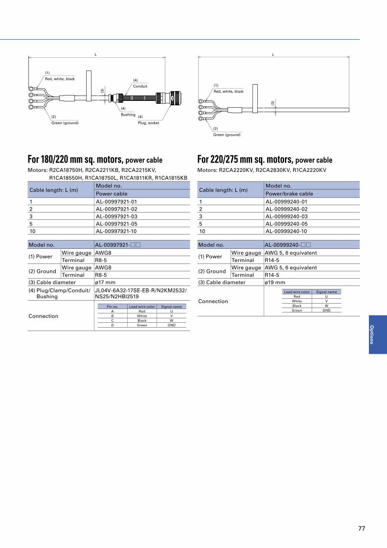
(4)
Plug, socket
(2)
Green (ground)
(4)
Conduit
(1)
Red, white, black
L
(3)
(4)
Bushing
For 180/220 mm sq. motors, power cableMotors: R2CA18750H, R2CA2211KB, R2CA2215KV,
R1CA18550H, R1CA18750L, R1CA1811KR, R1CA1815KB
Cable length: L (m)Model no.Power cable
1 AL-00997921-012 AL-00997921-023 AL-00997921-035 AL-00997921-0510 AL-00997921-10
Model no. AL-00997921-□□
(1) PowerWire gauge AWG8Terminal R8-5
(2) GroundWire gauge AWG8Terminal R8-5
(3) Cable diameter ø17 mm
(4) Plug/Clamp/Conduit/Bushing
JL04V-6A32-17SE-EB-R/N2KM2532/ NS25/N2HBI2519
Connection
Pin no. Lead wire color Signal nameA Red UB White VC Black WD Green GND
Servo Motor Power Cable
(2)
Green (ground)
(1)
Red, white, black
L
(3)
For 220/275 mm sq. motors, power cableMotors: R2CA2220KV, R2CA2830KV, R1CA2220KV
Cable length: L (m)Model no.Power/brake cable
1 AL-00999240-012 AL-00999240-023 AL-00999240-035 AL-00999240-0510 AL-00999240-10
Model no. AL-00999240-□□
(1) PowerWire gauge AWG 5, 6 equivalentTerminal R14-5
(2) GroundWire gauge AWG 5, 6 equivalentTerminal R14-5
(3) Cable diameter ø19 mm
Connection
Lead wire color Signal nameRed U
White VBlack WGreen GND
77
Op
tion
s

Power Connector to Connect Motor, Electric Wire SizeManufacturer: Japan Aviation Electronics Industry, Limited
The connectors listed below are single items. Note that cables are not included.
Flangesize(mm)
Motor modelno.
For power standard specificationFor power waterproofing specification
TÜV standard plugFor brake standard specification waterproof
specification TÜV standard plug(1) Plug (manufacturer model no.)(2) Cable clamp (manufacturer model no.)(3) Plug + cable clamp (SANYO DENKI part numbers)
(1) Plug (manufacturer model no.)(2) Cable clamp (manufacturer model no.)(3) Plug + cable clamp (SANYO DENKI part numbers)
(1) Plug (manufacturer model no.)(2) Cable clamp (manufacturer model no.)(3) Plug + cable clamp (SANYO DENKI part numbers)
Straight Angle Straight Angle Straight Angle
100 sq.R2CA10075F (1) N/MS3106B20-15S
(2) N/MS3057-12A(3) MS06B20-15S-12
(1) N/MS3108B20-15S(2) N/MS3057-12A(3) MS08B20-15S-12
(1) JL04V-6A20-15SE-EB-R(2) JL04-2220CK(14)-R(3) 332706X5
(1) JL04V-8A20-15SE-EBH-R(2) JL04-2220CK(14)-R(3) 332707X5
Same part number as for powerR2CA10100F
130 sq.
R2CA13050D
(1) N/MS3106B24-11S(2) N/MS3057-16A(3) MS06B24-11S-16
(1) N/MS3108B24-11S(2) N/MS3057-16A(3) MS08B24-11S-16
(1) JL04V-6A24-11SE-EB-R(2) JL04-2428CK(17)-R(3) 332706X10
(1) JL04V-8A24-11SE-EBH-R(2) JL04-2428CK(17)-R(3) 332707X10
Same part number as for power
R2CA13120R
R2CA13120F
R2CA13180H
R2CA13180D
R2CA13200L
R2CA13200H
180 sq.
R2CA18350L
(1) N/MS3106B24-11S(2) N/MS3057-16A(3) MS06B24-11S-16
(1) N/MS3108B24-11S(2) N/MS3057-16A(3) MS08B24-11S-16
(1) JL04V-6A24-11SE-EB-R(2) JL04-2428CK(17)-R(3) 332706X10
(1) JL04V-8A24-11SE-EBH-R(2) JL04-2428CK(17)-R(3) 332707X10
Same part number as for power
R2CA18350D
R2CA18450H
R2CA18550R
R2CA18550H
R2CA18750H(1) N/MS3106B32-17S(2) N/MS3057-20A(3) MS06B32-17S-20
(1) N/MS3108B32-17S(2) N/MS3057-20A(3) MS08B32-17S-20
(1) JL04V-6A32-17SE-R (Conduit)
(3) JL04V-6A32-17SE- (1) JL04V-6A10SL-3SE-EB-R
(2) JL04-1012CK(05)-R(3) 332706X1
(1) JL04V-8A10SL-3SE-EBH-R(2) JL04-1012CK(05)-R(3) 332707X1220 sq.
R2CA2211KB
R2CA2215KV
R2CA2220KV Terminal block; therefore, plug is not necessary
275 sq. R2CA2830KV Terminal block; therefore, plug is not necessary
100 sq.R1CA10150V (1) N/MS3106B20-15S
(2) N/MS3057-12A(3) MS06B20-15S-12
(1) N/MS3108B20-15S(2) N/MS3057-12A(3) MS08B20-15S-12
(1) JL04V-6A20-15SE-EB-R(2) JL04-2220CK(14)-R(3) 332706X5
(1) JL04V-8A20-15SE-EBH-R(2) JL04-2220CK(14)-R(3) 332707X5
Same part number as for powerR1CA10200V
130 sq. R1CA13300V(1) N/MS3106B24-11S(2) N/MS3057-16A(3) MS06B24-11S-16
(1) JL04V-8A24-11SE-EBH-R(2) JL04-2428CK(17)-R(3) 332707X10
(1) JL04V-6A24-11SE-EB-R(2) JL04-2428CK(17)-R(3) 332706X10
(1) JL04V-8A24-11SE-EBH-R(2) JL04-2428CK(17)-R(3) 332707X10
Same part number as for power
180 sq.
R1CA18550H
(1) N/MS3106B32-17S(2) N/MS3057-20A(3) MS06B32-17S-20
(1) N/MS3108B32-17S(2) N/MS3057-20A(3) MS08B32-17S-20
(1) JL04V-6A32-17SE-R (Conduit)
(3) JL04V-6A32-17SE-
(1) JL04V-6A10SL-3SE-EB-R(2) JL04-1012CK(05)-R(3) 332706X1
(1) JL04V-8A10SL-3SE-EBH-R(2) JL04-1012CK(05)-R(3) 332707X1
R1CA18750L
R1CA1811KR
R1CA1815KB
220 sq. R1CA2220KV Terminal block; therefore, plug is not necessary -
・ See the catalogs and instruction manuals of the connector manufacturer (Japan Aviation Electronics Industry, Limited) for how to handle the items and precautions.・ Conduit is not provided.
78
Options

Power Connector to Connect Motor, Electric Wire SizeManufacturer: Japan Aviation Electronics Industry, Limited
Flangesize(mm)
Motor modelno.
Pin layout symbol Applicableamplifiercapacity
Recommended motor power wire size(U, V, W, GND)
Wire size of main power supply(R, S, T, GND)
U phase V phase W phase Ground Brake mm2 AWG No. mm2 AWG No.
100 sq.R2CA10075F
A B C D E, F25 A 1.25 #16 1.25 #16
R2CA10100F 50 A 2 #14 2 #14
130 sq.
R2CA13050D
D E F G, H A, B
25 A 1.25 #16 1.25 #16R2CA13120R
R2CA13120F 50 A 2 #14 2 #14
R2CA13180H 25 A 1.25 #16 1.25 #16
R2CA13180D 50 A 2 #14 2 #14
R2CA13200L 25 A 1.25 #16 1.25 #16
R2CA13200H50 A 2 #14 2 #14
180 sq.
R2CA18350L
D E F G, H A, B
R2CA18350D
100 A 3.5 #12 2 #14R2CA18450H
R2CA18550R
R2CA18550H
150 A
5.5 #10
5.5 #10R2CA18750H
A B C D A, B* 8 #8
220 sq.
R2CA2211KB
R2CA2215KV
R2CA2220KV Terminal block A, B*300 A 14 #6 14 #6
275 sq. R2CA2830KV Terminal block
100 sq.R1CA10150V
A B C D E, F25 A 1.25 #16 1.25 #16
R1CA10200V 50 A 2 #14 2 #14
130 sq. R1CA13300V D E F G, H A, B 50 A 2 #14 2 #14
180 sq.
R1CA18550H
A B C D A, B* 150 A 8 #8 5.5 #10R1CA18750L
R1CA1811KR
R1CA1815KB
220 sq. R1CA2220KV Terminal block - 300 A 14 #6 14 #6* The brake connector is separated.
Plug for power and brake (straight)
Plug for power and brake (angle)
Combination plug for encoder (angle) Receptacle for power and brake
Encoder receptacle
Cable clamp for power and brake
Cable clamp for power and brake
Combination plug for encoder (straight)
Cable
Cable
79
Op
tion
s

Encoder ConnectorThe connectors listed below are single items. Note that cables are not included.
Combination plug for encoder(with rubber bushing)
Encoder receptacle model number(motor side)
Applicable cable diameter (bushing color phase)
Pin Layout Symbol RemarksStraight Angle
JN2DS10SL1-R JN2FS10SL1-R
JN2AS10ML2-R
ø5.7 to 7.3 mm (Black)
See the encoder wiring diagram for each servo amplifier.
Japan Aviation Electronics Industry, Limited
JN2DS10SL2-R JN2FS10SL2-Rø6.5 to 8.0 mm (Gray)
JN2DS10SL3-R JN2FS10SL3-Rø3.5 to 5.0 mm (Brick)
5557-10R 5559-10P - Molex Japan Co., Ltd.Select the correct plug and contact for the cable size to use. Our ordering numbers are the same as the manufacturer part numbers.
Applicable contact for encoder plug*1, 2
Contact size CategoryApplicable contact
RemarksSocket contact model no. Applicable wire size
#22Manual crimp tool type *3, 4
JN1-22-20S-R-PKG100 AWG #20
Japan Aviation Electronics Industry, Limited
JN1-22-22S-PKG100 AWG #21 to #25
JN1-22-26S-PKG100 AWG #26 to #28
Solder type JN1-22-22F-PKG100 AWG #20
#28 Manual crimp tool type *3, 45556T2L
AWG #22 to #28 Molex Japan Co., Ltd.5556GS2
*1 Select the correct plug and contact for the cable size to use. Our ordering numbers are the same as the manufacturer part numbers.*2 When removing an inserted contact, use a removal tool. Use a commercially available one.*3 For part numbers of manual crimp tools, see the instruction manuals issued by the connector manufacturer.*4 For semi-automatic crimp tools, purchase from the respective manufacturers.For precautions or how to handle connectors and contacts, refer to the catalogs and instruction manuals of the respective manufacturers.
80
Options

Cable
Cable length: L (m) Model no.
1 AL-00999243-01
2 AL-00999243-02
3 AL-00999243-03
5 AL-00999243-05
10 AL-00999243-10
Type Connector model no. Remarks
Motor side connector - Connector not processed
Amplifier side connector Receptacle: 36210-0100PL Shell kit: 36310-3200-008 3M Japan Limited
Pin no. Lead wire color Signal name1 Red 5 V2 Black 0 V7 Brown ES+8 Blue ES-9 Green EBAT+10 Purple EBAT-
L
(Ø6.
7)
3631
03M
Note: A cable with a plug on the motor side needs to be prepared by the customer.
Motor: R2CA2830KV
■USB communication cable for setup softwarePC communication cable for setup software
Cable length: L (m) Model no.
1.0 AL-00896515-01
2.0 AL-00896515-02
■Communication cable between amplifiers for tandem operationConnects between amplifiers for tandem operation. (CN5⇔CN5)
Cable length: L (m) Model no.
0.2 AL-00911582-01
3.0 AL-00911582-02
Note: Dedicated for Analog/Pulse type amplifiers. Cannot be used with EtherCAT amplifiers.
L
PC side (USB type A) Servo ampli�er side (USB mini B)
B
Specifications and external drawings may be changed without prior notice.
NO.8 NO.1L
NO.8 NO.1
■ Servo motor encoder cableMotor: Not R2CA2830KV
Cable length: L (m) Model no.
1 AL-00937694-01
2 AL-00937694-02
3 AL-00937694-03
5 AL-00937694-05
10 AL-00937694-10
Type Connector model no. Remarks
Motor side connector Straight plug: JN2DS10SL2-RContact: JN1-22-22F-PKG100
Japan Aviation Electronics Industry, Limited
Amplifier side connector Receptacle: 36210-0100PLShell kit: 36310-3200-008 3M Japan Limited
UN
L
(ø6.
7)
Pin no. Lead wire color Signal name1 Brown ES+2 Blue ES-4 Purple EBAT-8 Green EBAT+9 Red 5 V10 Black 0 V7 Shielded GND
Pin no. Lead wire color Signal name1 Red 5 V2 Black 0 V7 Brown ES+8 Blue ES-9 Green EBAT-10 Purple EBAT+
Note: Only straight plugs are available for this cable.Cables with angled plugs are not available.
81
Op
tion
s

■ Servo motor cooling fan power cableMotors: R1CA18550H, R1CA18750L, R1CA1811KR, R1CA1815KB, R1CA2220KV
Cable length: L (m)Model no.
Power cable
1 AL-00997923-01
2 AL-00997923-02
3 AL-00997923-03
5 AL-00997923-05
10 AL-00997923-10
Type Connector model no. Remarks
Motor side connector Plug: N/MS3106B10SL-4S Clamp: N/MS3057-4A Japan Aviation Electronics Industry, Limited
L
White, white
(Ø4.
8)
AWG20
Motor: R2CA2830KV
Cable length: L (m)Model no.
Power cable
1 AL-00999241-01
2 AL-00999241-02
3 AL-00999241-03
5 AL-00999241-05
10 AL-00999241-10
Type Connector model no. Remarks
Motor side crimp terminal - Both end terminals not crimped
L
(Ø6.
1)
■ Servo motor brake cableMotors: R2CA18750H, R2CA2211KB, R2CA2215KV, R2CA2220KV
R1CA18550H, R1CA18750L R1CA1811KR, R1CA1815KB
Cable length: L (m)Model no.
Power cable
1 AL-00918630-01
2 AL-00918630-02
3 AL-00918630-03
5 AL-00918630-05
10 AL-00918630-10
Type Connector model no. Remarks
Motor side connector Plug: JL04V-6A10SL-3SE-EB-R Clamp: JL04-1012CK(05)-R Japan Aviation Electronics Industry, Limited
Motor: R2CA2830KV
Cable length: L (m)Model no.
Power cable
1 AL-00999239-01
2 AL-00999239-02
3 AL-00999239-03
5 AL-00999239-05
10 AL-00999239-10
Type Connector model no. Remarks
Motor side crimp terminal - Motor side terminal not crimped
L
120±7
N1.25-4 by JST
(Ø5.
9)
Straight plug by JAE: JL04V-6A10SL-3SE-EB-RCable clamp: JL04-1012CK(05)-R
L
White, white
(Ø4.
8)
AWG20
Terminal by JST: N1.25-4
Cable
82
Options

Cable■ Servo motor cooling fan thermostat cableMotor: R2CA2830KV
Cable length: L (m)Model no.
Power cable
1 AL-00999242-01
2 AL-00999242-02
3 AL-00999242-03
5 AL-00999242-05
10 AL-00999242-10
Type Connector model no. Remarks
Motor side connector - Motor side terminal not crimped
L
(Ø5.
0)
Terminal by JST: N1.25-4
83
Op
tion
s

Analog Monitor
Op
tion
s
This is an analog monitor that can display velocity waveforms on an oscilloscope for the purpose of system tuning or maintenance.
Name Description Model no.
1) Monitor box Monitor box body2 dedicated cables Q-MON-3
2) Dedicated cable 1 dedicated cable AL-00690525-01
Front Mounting Brackets
4110
506
75R3
2-C5
15
R1 max.
Top and bottom mounting brackets are identical
Dimensions (Unit: mm)
This is a pair of metal brackets for mounting a 25 A servo amplifier on the front face (the face with connectors).50 and 100 A models can be mounted on the front face too by removing the attached back-mounting brackets from the amplifier and using them for front-mounting.
Applicable servo amplifiers Model no. Set contents
25 A (RS3C02) AL-00962547-01 Top/bottom mounting brackets: 1 eachClamping screws: 6
1) Monitor box (Q-MON-3)
29
44
65
20
2) Dedicated cable (AL-00690525-01)
*1 Dedicated cables per above 2) (AL-00690525-01) are included with the monitor box (Q-MON-3).
*2 Power is supplied from the servo amplifier.
2020
421
3
20002020
1A2A2B
1B
Monitor box side Servo ampli�er side
Brown Black
External Regenerative Resistor
Model no. Rated power [PR] ResistanceDetected temperature of thermostat (Contact specifications)
REGIST-500CW80B 500 W 80 Ω 100˚C ±5˚C (contact b)
REGIST-500CW40B 500 W 40 Ω 100˚C ±5˚C (contact b)
REGIST-500CW20B 500 W 20 Ω 100˚C ±5˚C (contact b)
REGIST-500CW14B 500 W 14 Ω 100˚C ±5˚C (contact b)
REGIST-500CW7B 500 W 7 Ω 100˚C ±5˚C (contact b)
8234
250
60
Thermostat
700
8035
4.5
3
350
Lead wire AWG24 0.2 mm2, White
Ground mark
2-ø4.5
2-M3
Solderless terminal (for M5)Lead wire AWG14 2 mm2, WhiteMass: 1.4 kg
84
Options

Analog Monitor
Op
tion
s
Servo Motor Capacity Selection (Rotary Motor)
This is a method of calculating the required capacity of servo motors from the mechanical specifications.Here we have introduced the basic selection procedure focusing on a ball screw (flat) mechanism.
Selection procedure
1. Creation of operation patterns
Create the operation patterns.
2. Calculation of conversion of motor shaft moment of load
inertia JL
Calculate the moment of load inertia from the machine
configuration.
3. Calculation of load torque TL for motor shaft conversion
Calculate the load torque from the machine configuration.
4. Provisional selection of servo motor capacity
Provisionally select a motor in which the load moment of
inertia (JL) is 10 times or less than the rotor moment of inertia
(JM) of servo motor, while the load torque (TL) is 80% or less
(TR x 0.8) of rated torque of motor (TR).
JL ≤ JM × 10
TL ≤ TR × 0.8
5. Calculation of acceleration/deceleration torque
Calculate the required acceleration/deceleration torque from
the operation patterns.
6. Calculation of effective torque
Calculate the effective torque from the torque patterns.
7. Judgment
Determine whether the acceleration and deceleration torque
(Ta, Tb) are 80% (Tp x 0.8) or less than the peak stall torque (Tp)
of the servo motor; and the effective torque (Trms) is 80% (TR
x 0.8) or less than the rated torque (TR) of the servo motor.
Ta ≤ Tp × 0.8
Tb ≤ Tp × 0.8
Trms ≤ TR × 0.8
If the judgment results cannot be applied in the aforementioned
equation, reconsider the servo motor capacity, for example
increasing the capacity.
8. Calculation of regenerative power
Calculate the regenerative power and select an external
regenerative resistor if necessary.
1. Creation of operation patterns
First, determine the equipment mechanism, dimensions of all
parts, positioning amount, positioning time, gear ratio, etc. An
operation pattern is the determined driving force plotted on the
speed/time axis.
Speed [min-1]
Time [s]
N2
N1ta tr
tc tst
tb
ta = Acceleration time [s]
tb = Deceleration time [s]
tr = Constant speed-time [s]
ts = Downtime [s]
t = 1 cycle [s]
2. Calculation of conversion of motor shaft moment of load inertia JL
Load moment of inertia is the quantity showing inertia of a
rotating object.
Given below is the calculation method used in case of ball screw
(flat) mechanism.
■ Ball screw moment of inertia
[kg∙m2]
[kg∙m2]
[N∙m]
[N∙m]
[N∙m]
[N∙m]
JL1=
JL2= W
1 2
G×
32
π×ρ×D4×L( )
1 2
G× ×
× × × 9.8
( )P 2
2π
TL=
Ta=
P
2π
1
G
(F+μW)
η
+ TL2π(N2-N1)×(JL+JM)
60×ta
Tb=
Trms=
EM = Ehb = × N × 3 × Keø × × tb - × 3 × Rø × tb
- TL2π(N2-N1)×(JL+JM)
60×tb
(Ta2×ta) + (TL2×tr) + (Tb2×tb)
t
( )
1
2
Tb
KT
Tb
KT
2
G: Gear ratio
ρ: Ball screw specific gravity [kg/m3] [Iron: 7.8 × 10³]
D: Ball screw diameter [m]
L: Ball screw length [m]
■ Work + table moment of inertia
[kg∙m2]
[kg∙m2]
[N∙m]
[N∙m]
[N∙m]
[N∙m]
JL1=
JL2= W
1 2
G×
32
π×ρ×D4×L( )
1 2
G× ×
× × × 9.8
( )P 2
2π
TL=
Ta=
P
2π
1
G
(F+μW)
η
+ TL2π(N2-N1)×(JL+JM)
60×ta
Tb=
Trms=
EM = Ehb = × N × 3 × Keø × × tb - × 3 × Rø × tb
- TL2π(N2-N1)×(JL+JM)
60×tb
(Ta2×ta) + (TL2×tr) + (Tb2×tb)
t
( )
1
2
Tb
KT
Tb
KT
2
G: Gear ratio
W: Work + table mass [kg]
P: Ball screw pitch [m]
■ Conversion of motor shaft moment of load inertia.
JL=JL1+JL2
* Moments of inertia of reducer and coupling are assumed to be
negligible and have therefore been omitted.
85
Selectio
n
Gu
ide

Servo Motor Capacity Selection (Rotary Motor)
3. Calculation of load torque TL for motor shaft conversion
Load torque is the power generated from the friction of the driving part or from the gravity that is converted on the motor shaft. When activated, this torque always acts as the load.Given below is the calculation method used in the case of a ball screw (flat) mechanism.
[kg∙m2]
[kg∙m2]
[N∙m]
[N∙m]
[N∙m]
[N∙m]
JL1=
JL2= W
1 2
G×
32
π×ρ×D4×L( )
1 2
G× ×
× × × 9.8
( )P 2
2π
TL=
Ta=
P
2π
1
G
(F+μW)
η
+ TL2π(N2-N1)×(JL+JM)
60×ta
Tb=
Trms=
EM = Ehb = × N × 3 × Keø × × tb - × 3 × Rø × tb
- TL2π(N2-N1)×(JL+JM)
60×tb
(Ta2×ta) + (TL2×tr) + (Tb2×tb)
t
( )
1
2
Tb
KT
Tb
KT
2
F: External force [kg]η: Machine efficiencyμ: Coefficient of frictionW: Work + table mass [kg]P: Ball screw lead [m]G: Gear ratio
4. Provisional selection of servo motor capacity
Provisionally select the motors that apply to the following 2 conditions.・ Load moment of inertia (JL) calculated in step 2 is 10 times or
less than the rotor moment of inertia (JM) of servo motor JL ≤ JM × 10・ Load torque (TL) calculated in step 3 is 80% or less (TR × 0.8) of
rated torque (TR) of servo motor TL ≤ TR × 0.8
5. Calculation of acceleration/deceleration torque
Acceleration/deceleration torque is necessary for accelerating and decelerating the motor and load.
■ Method of obtaining acceleration torque (Ta)
[kg∙m2]
[kg∙m2]
[N∙m]
[N∙m]
[N∙m]
[N∙m]
JL1=
JL2= W
1 2
G×
32
π×ρ×D4×L( )
1 2
G× ×
× × × 9.8
( )P 2
2π
TL=
Ta=
P
2π
1
G
(F+μW)
η
+ TL2π(N2-N1)×(JL+JM)
60×ta
Tb=
Trms=
EM = Ehb = × N × 3 × Keø × × tb - × 3 × Rø × tb
- TL2π(N2-N1)×(JL+JM)
60×tb
(Ta2×ta) + (TL2×tr) + (Tb2×tb)
t
( )
1
2
Tb
KT
Tb
KT
2
N2: Servo motor rotary speed after acceleration [min-1]N1: Servo motor rotary speed before acceleration [min-1]JL: Conversion of motor shaft moment of load inertia [kg∙m2]JM: Conversion of servo motor moment of rotor inertia [kg∙m2]TL: Calculation of load torque for motor shaft conversion [N∙m]ta: Acceleration time [s]
■ Method of obtaining deceleration torque (Tb)
[kg∙m2]
[kg∙m2]
[N∙m]
[N∙m]
[N∙m]
[N∙m]
JL1=
JL2= W
1 2
G×
32
π×ρ×D4×L( )
1 2
G× ×
× × × 9.8
( )P 2
2π
TL=
Ta=
P
2π
1
G
(F+μW)
η
+ TL2π(N2-N1)×(JL+JM)
60×ta
Tb=
Trms=
EM = Ehb = × N × 3 × Keø × × tb - × 3 × Rø × tb
- TL2π(N2-N1)×(JL+JM)
60×tb
(Ta2×ta) + (TL2×tr) + (Tb2×tb)
t
( )
1
2
Tb
KT
Tb
KT
2
N2: Servo motor rotary speed before deceleration [min-1]N1: Servo motor rotary speed after deceleration [min-1]JL: Conversion of motor shaft moment of load inertia [kg∙m2]JM: Conversion of servo motor moment of rotor inertia [kg∙m2]TL: Calculation of load torque for motor shaft conversion [N∙m]tb: Deceleration time [s]
6. Calculation of effective torque
Effective torque is the value per unit time obtained from root mean square of load torque / acceleration torque / deceleration torque .
[kg∙m2]
[kg∙m2]
[N∙m]
[N∙m]
[N∙m]
[N∙m]
JL1=
JL2= W
1 2
G×
32
π×ρ×D4×L( )
1 2
G× ×
× × × 9.8
( )P 2
2π
TL=
Ta=
P
2π
1
G
(F+μW)
η
+ TL2π(N2-N1)×(JL+JM)
60×ta
Tb=
Trms=
EM = Ehb = × N × 3 × Keø × × tb - × 3 × Rø × tb
- TL2π(N2-N1)×(JL+JM)
60×tb
(Ta2×ta) + (TL2×tr) + (Tb2×tb)
t
( )
1
2
Tb
KT
Tb
KT
2
7. Judgment
Our company’s judgment criteria are as follows.・ Load torque load factor TL ≤ TR × 0.8 (Load torque is 80% or less of rated torque)
・ Acceleration torque load factor Ta ≤ TP × 0.8 (Acceleration torque is 80% or less of peak stall torque) TP: Peak stall torque
・ Deceleration torque load factor Tb ≤ TP × 0.8 (Deceleration torque is 80% or less of peak torque at stall) TP: Peak stall torque
・ Effective torque load factor Trms ≤ TR × 0.8 (Effective torque is 80% less than rated torque)
・Moment of inertia ratio JL ≤ JM × 10 (Load moment of inertia is 10 times or less than the rotor
moment of inertia of motor)
Rise in motor temperature can be suppressed by keeping a large margin in torque load factor. The moment of inertia ratio can be controlled at 10 times or more, for example, by slowly rotating the table mechanism. Testing with an actual machine is recommended.
8. Calculation of regenerative power
Calculate the regenerative efficient power (PM) to determine the regenerative resistor to be used. From the calculation results, determine whether a built-in regenerative resistor can be used.
■ Method of obtaining regenerative efficient power (PM) of horizontal drive shaftDerive the regenerative energy.
[kg∙m2]
[kg∙m2]
[N∙m]
[N∙m]
[N∙m]
[N∙m]
JL1=
JL2= W
1 2
G×
32
π×ρ×D4×L( )
1 2
G× ×
× × × 9.8
( )P 2
2π
TL=
Ta=
P
2π
1
G
(F+μW)
η
+ TL2π(N2-N1)×(JL+JM)
60×ta
Tb=
Trms=
EM = Ehb = × N × 3 × Keø × × tb - × 3 × Rø × tb
- TL2π(N2-N1)×(JL+JM)
60×tb
(Ta2×ta) + (TL2×tr) + (Tb2×tb)
t
( )
1
2
Tb
KT
Tb
KT
2
EM: Regenerative energy in case of horizontal drive shaft [J]Ehb: Regenerative energy during deceleration [J]Keø: Induced voltage constant [Vrms/min-1] (motor constant)KT: Torque constant [N∙m/Arms] (motor constant)N: Motor rotary speed [min-1]Rø: Armature resistance [Ω] (motor constant)tb: Deceleration time [s]Tb: Deceleration torque [N∙m]
Derive the regenerative efficient power from regenerative energy.
PM =EM
t
PM: Regenerative efficient power [W]EM: Regenerative energy [J]t: Cycle time [s]
■ Selection of regenerative resistorSelect a regenerative resistor that meets the following conditions.・ In case of servo amplifiers with a built-in regenerative resistor:
Permissible regenerative power [PR] that is less than efficient regenerative power [PM] and can be used with built-in regenerative resistors
・ In case of external regenerative resistor:Permissible regenerative power [PRO] that is less than efficient regenerative power [PM] and can be used with external regenerative resistors
Note that we have servo amplifier models both with and without built-in regenerative resistors for absorbing regenerative power. Select the model accordingly.
86
Selection Guide

Ball screw Rack & pinion
External force F N
W: Work + table mass W kg
Ball screw diameter D m
Ball screw length L m
Ball screw lead P m
Ball screw material specific gravity ρ kg/m3
Coefficient of friction μ
Gear ratio * G
Machine efficiency η
External force F N
Work + rack mass W kg
Pinion diameter D m
Pinion thickness L m
Pinion material specific gravity ρ kg/m3
Coefficient of friction μ
Gear ratio * G
Machine efficiency η
Belt drive Roll feed
External force F N
Work + belt mass W kg
Pulley diameter D m
Pulley width L m
Pulley material specific gravity ρ kg/m3
Pulley moment of inertia J kg∙m2
Gear ratio * G
Machine efficiency η
Sheet tension F N
Roll diameter D m
Roll width L m
Roll material specific gravity ρ kg/m3
Roll moment of inertia J kg∙m2
Gear ratio * G
Machine efficiency η
Rotary table
Table mass W kg
Table diameter Dt m
Table support diameter Dh m
Table moment of inertia J kg∙m2
Support part coefficient of friction μ
Gear ratio * G
Machine efficiency η
Typical examples of mechanisms and items that require selection are shown below. Provide this information when placing an order.
D
Work
Work
Timing belt
L
Work
Rack
Pinion
Table
L
External force External force
F
D
PM
M
M
D
D
M
LExternal force
M
Dt
Dh
D
Work
Work
Timing belt
L
Work
Rack
Pinion
Table
L
External force External force
F
D
PM
M
M
D
D
M
LExternal force
M
Dt
Dh
* Derivation of gear ratio (G)
MG1
G=Ball screw gear teeth (G2)
Motor gear teeth (G1)
G2 Ball screw
D
Work
Work
Timing belt
L
Work
Rack
Pinion
Table
L
External force External force
F
D
PM
M
M
D
D
M
LExternal force
M
Dt
Dh
Selection Data for Each Mechanism
87
Selectio
n
Gu
ide

Motor Protection Rating
Code character (Ingress Protection)
Second digit(A number from 0 to 8 or the letter X)
First digit(A number from 0 to 6 or the letter X)
SANYO DENKI servo motor protection ratings are determined in accordance with IEC Standard (IEC 60529, IEC 60034-5) and JIS Standard (JIS C 0920, JIS C 4034-5)
The protection rating (IP code), is defined by IEC (International Electrotechnical Commission) 60529 "DEGREES OF PROTECTION PROVIDED BY ENCLOSURES (IP Code)."Note: IEC 60529
I P 6 5
First digit Description Definition
0 No protection -
1 Protection against solid objects > 50 mm A spherical 50 mm diameter solid probe shall not completely penetrate
2 Protection against solid objects > 12.5 mm A spherical 12.5 mm diameter solid probe shall not completely penetrate
3 Protection against solid objects > 2.5 mm A spherical 2.5 mm diameter solid probe shall not penetrate at all
4 Protection against solid objects > 1 mm A spherical 1 mm diameter solid probe shall not penetrate at all
5Protection against a level of dust that could hinder operation or impair safety
Although it is impossible to completely prevent the penetration of dust, there should be no intrusion of an amount of dust that could impede the prescribed operation and safety of the electrical equipment
6 Complete protection against dust Completely protected against dust
Second digit Description Definition
0 No protection -
1Protected against vertically falling drops of water
Vertically dripping water shall have no harmful effect.
2Protected against vertically falling drops of water even if inclined up to 15°
Vertically dripping water shall have no harmful effect when the enclosure is tilted at an angle up to 15° from its normal position.
3 Protected against spraying waterWater falling as a spray at any angle up to 60° from the vertical shall have no harmful effect.
4 Protected against splashing waterWater splashing against the enclosure from any direction shall have no harmful effect.
5 Protected against water jetsWater projected by a nozzle against enclosure from any direction shall have no harmful effects.
6 Protected against powerful water jetsWater projected in powerful jets against the enclosure from any direction shall have no harmful effects.
7Protected against temporary immersion in water
Ingress of water in harmful quantity shall not be possible when the enclosure is immersed in water under defined conditions of pressure and time.
8 Protected against submersion in waterThe equipment is suitable for continuous immersion in water under conditions which negotiated with stakeholders. The test conditions are expected to be greater than the requirements for IPx7, and other environmental effects may be added.
· According to the standard, "the liquid used for the test is to be fresh water," and liquids other than water such as oil are not included in the test conditions.
Separate evaluation is necessary when used in environments where machine tool cutting oil is present. Our servo motors have a proven track record for machine tool applications, and we can respond with options, so please contact us as
necessary.· For the second digit, values of 6 and under indicate compliance with all lower conditions, however when the second digit is 7 it does not
indicate protection against jets (indicated by a second digit of 5 or 6) Select a protection rating suitable for your environment.
Protection rating
88

Safety PrecautionsThe products in this catalog are designed to be used with general industrial devices.Pay sufficient attention to the following:
・ Read the Instruction Manual carefully prior to installation, assembly, or operation for the correct usage. The Instruction Manual is available for download from our website.・Refrain from modifying or processing the product in any way.・Contact your point of sale or specialized service provider for installation or maintenance services of the product.・ Consult with us when using the product for the following uses, as these require special considerations for operations, maintenance,
and management such as redundancy and emergency power generators.
❶ Use in medical equipment or other devices that may directly affect people’s lives or cause bodily injury❷ Use in transportation systems or transport-related equipment such as trains or elevators, that may affect people’s lives or
cause bodily injury❸ Use in computer systems that may have a major impact on society or on the public❹ Use in other devices that have a significant impact on human safety or on maintaining public operations
・Consult with us when using the product in an environment where vibrations occur, such as in a moving vehicle or during transportation.・Use the product only after becoming thoroughly proficient with relevant product knowledge, safety information, and precautions.
Warning Labels on ProductsProducts bear the following Warning Labels to indicate the situations as below, depending on the model.
This label is attached in the vicinity of high-voltage portions such as charging or cover-protected parts, to indicate locations with risk of electric shock.
This label is attached in the vicinity of grounding terminals to indicate that grounding is required.
Safety Ranks of the CautionsThe following five safety symbols are used in the manual.
Indicates immediate hazards that will cause severe bodily injury or death as a result of failure to follow the instructions.
Indicates hazards that could cause severe bodily injury or death as a result of failure to follow the instructions.
Indicates possible hazards that could cause moderate bodily injury or only property damage as a result of failure to follow the instructions.
Note that even items with the symbol could potentially lead to serious outcomes, depending on the situation.They all indicate important situations, so be sure to observe them.
Indicates actions that must not be taken.
Indicates actions that must be taken.
89

WARNING
Precautions on Use1. Do not use the product in explosive environments. Failure to follow this
may cause injury or fire.2. Do not work on wiring, maintenance servicing, or inspection with the
power on. After turning off the power, wait at least 15 minutes and confirm extinction of CHARGE-LED for the main circuit power supply, and then start working. Failure to follow this may cause electric shock or product damage.
3. Make sure to ground protective grounding terminals of servo amplifiers to equipment or control board. The grounding terminals of servo motors must be connected to protective grounding terminals of servo amplifiers. Failure to follow this may cause electrical shock.
4. Never touch inside of servo amplifiers with hands. Electrical shock may result.
5. Do not damage, apply excessive stresses, put heavy things on, or tuck down cables. Failure to follow this may cause electrical shock.
6. Never touch the rotating part of servo motors during operation. Failure to follow this may cause injury.
CAUTION
Precautions on Use1. Use servo amplifiers and servo motors in specified combinations. Failure to
follow this may cause fire or product malfunctions.2. Only technically qualified personnel should transport, install, wire, operate,
or perform maintenance and inspection on the product. Failure to follow this may cause electric shock, injury, or fire.
3. Never install the product in a location exposed to water, in a corrosive or flammable gas atmosphere, or in the vicinity of flammable materials. Failure to follow this may cause fire or product malfunctions.
4. Be careful of the high temperatures generated by the servo amplifier/motor and the peripherals. Failure to follow this may cause burns.
5. Never touch regenerative resistors, servo motors, and the radiation fin of servo amplifiers as such equipment reach high temperatures in operation and remain hot for a while after the power is turned off. Failure to follow this may cause burns.
6. When designing a safety system that utilizes Safe Torque Off function, it must be designed by individuals who have specialized knowledge on relevant safety standards after reading and understanding the descriptions of the Instruction Manual. Failure to follow this may cause injury or product failures.
7. Be sure to read the Instruction Manual in advance, and follow the instructions when performing installation, operation, maintenance, and inspection work. Failure to follow this may cause electric shock, injury, or fire.
8. Do not use servo amplifiers and servo motors outside their specified operating ranges. Failure to follow this may cause electric shock, injury, or product damage.
9. For use in high inertial moment or high-speed applications that require high regenerative power that excesses the capability of the wires in the regenerative resistor, consult us.
Transportation10. When transporting, do not hold the cables, servo motor shafts, or detector
parts. Failure to follow this may cause product damage or injury.11. Handle the product with care during transportation to prevent it from
dropping or falling. Failure to follow this may cause injury.
Installation12. Do not stand on the product or place heavy objects on top of it. Failure to
follow this may cause injury.13. Make sure that the mounting orientation is correct. Failure to follow this
may cause fire or product malfunctions.14. Do not drop the product or subject it to excessive shock of any kind. Failure
to follow this may cause product failures.15. Do not obstruct the air intake and exhaust vents. Failure to follow this may
cause fire.16. Follow the Instruction Manual and give sufficient spacing within the servo
amplifier control board. Failure to follow this may cause fire or product malfunctions.
17. Unpack the box right side up. Failure to follow this may cause injury.18. Verify that the product you receive is the same product you ordered. Failure
to follow this may cause injury or product damage.19. Take care of falling or overturning of the product during installation. Use
eyebolts, if included, for transporting servo motors. Failure to follow this may cause injury.
20. Install the product to incombustible materials such as metals. Failure to follow this may cause fire.
21. For anti-collision devices, use ones that can withstand the maximum output of the system. Failure to follow this may cause injury.
Wiring22. Perform wiring correctly and securely. Failure to follow this may cause
injury.23. Perform wiring work according to the wiring diagrams or the Instruction
Manual. Failure to follow this may cause electric shock or fire.24. Perform wiring work according to local standards of electrical installations.
Failure to follow this may cause motor burnout or fire.
25. Do not connect commercial power supply to the U, V and W terminals of servo motors. Failure to follow this may cause fire or product malfunctions.
26. Install safety devices such as circuit breakers in preparation for short circuiting of external wiring. Failure to follow this may cause fire.
27. Do not bind or band the power cable, input/output signal cable and/or encoder cable together or pass through the same duct or conduit. Failure to follow this may cause faulty operation.
28. When connecting an inductive load such as a relay to the control output signal of the servo amplifier, be sure to connect a surge absorbing diode. Be aware that reverse-connecting the diode polarity may cause servo amplifier malfunctions.
29. Do not connect an AC or 90 VDC power supply to 24 VDC servo motor brakes. Furthermore, do not connect 400 VAC power supply to 200 VAC servo motor cooling fans. Failure to follow this may cause motor burnout or fire.
30. Arrange a relay sequence taking into consideration the delay in hold braking caused by surge absorbers for holding brake relays. Failure to follow this may result in falls or injury.
31. Do not use half-wave rectifier circuits in power supplies of 24 VDC or 90 VDC brakes. Failure to follow this may cause excessive heating or product failures.
Controls & Operations32. Do not perform drastic setting changes as such changes may cause
unstable operation. Failure to follow this may cause injury.33. Test-run a servo motor with the motor position fixed in isolation from the
machinery system. Install the motor to the machinery system only after verifying the motor operation. Failure to follow this may cause injury.
34. The holding brake cannot be used as a dynamic brake for achieving the safety of machinery. For that purpose, install stop devices. Failure to follow this may cause injury.
35. In the case of an alarm, make sure to eliminate the cause and ensure safety before resuming operations. Failure to follow this may cause injury.
36. Verify that the input power supply voltage is within the specified range. Failure to follow this may cause product failures.
37. After a power interruption, avoid getting close to a stopped device as it may restart suddenly. (Design a safety system to prepare for such an event.) Failure to follow this may cause injury.
38. Do not use servo amplifiers or servo motors that have failed, damaged, or burnt out. Failure to follow this may cause injury or fire.
39. Immediately stop operation in case of anomaly. Failure to follow this may cause electric shock, injury, or fire.
40. When using servo motors in vertical axes, install safety devices to prevent a workpiece from falling even in the event of an alarm. Failure to follow this may cause injury or product damage.
Maintenance & Inspection41. Parts and components used in servo amplifiers (such as electrolytic
capacitors, cooling fans, lithium batteries for encoders, fuses, relays, and the like) deteriorate by aging. Considering the standard replacement period, replace these parts and components with new ones for preventive maintenance. Failure to follow this may cause product failures. Contact us when replacing such parts and components.
42. Never touch terminals and connectors while electricity is supplied. Failure to follow this may cause electrical shock.
43. Since the frame of servo amplifiers becomes high in temperature, be careful when conducting maintenance and inspection work. Failure to follow this may cause burns.
44. Contact us for repairs. Disassembling the product by yourself may result in product failures and render it inoperable.
PROHIBITED
Storage1. Avoid storing the product in places exposed to rain or water drops, or in an
environment with hazardous gas or liquid. Failure to follow this may cause malfunctions.
Controls & Operations2. Brakes equipped with servo motors are intended for holding and must
not be used for dynamic braking. Failure to follow this may cause product damage or malfunctions.
3. Do not apply static electricity or excessively high voltage to servo motor encoder cables. Failure to follow this may cause malfunctions.
4. Never rotate servo motors continuously by external force when the amplifier is at "Servo OFF", because it will heat up the motor's standardly-equipped dynamic brake resistor, which is dangerous. Failure to follow this may cause fire or burns.
5. Never use the product with voltages exceeding the specified input voltage range. Failure to follow this may cause component failures, product damage, or injury.
6. Do not turn the power supply on and off frequently. Turning the power supply on and off more than 30 times a day or 5 times per hour may cause premature malfunctions of internal components.
Maintenance & Inspection7. Do not disassemble or repair the product by yourself. Failure to follow this
may cause fire or electric shock.8. Do not perform measurements of insulation resistance or dielectric voltage.
Failure to follow this may cause product damage.
90

Table 1
Servo amplifier model no. Power supply Circuit classification Circuit type Conversion factor Ki
RS3C02□□RS3C05□□RS3C10□□RS3C15□□RS3C30□□
3-Phase 3 3-Phase bridge(Condenser smooth)
3-1 6-pulse converter without reactor K31=3.4
3-2 6-pulse converter with reactor (AC side) K32=1.8
9. Never plug or unplug connectors with the power on (hot swapping) as the resulting surge voltage may cause electronic components malfunctions. Failure to follow this may cause electric shock or product damage.
10. Do not remove the product name plate.
MANDATORY
Storage1. Store the product where it is not exposed to direct sunlight, and within the
specified temperature and humidity ranges [ -20 to +65°C, below 90% RH (non-condensing)]. Failure to follow this may cause product malfunctions.
2. If servo amplifiers have been stored for a long period (3 years or longer), contact us. The capacitance of electrolytic capacitors can decrease due to the long period storage, which may cause malfunctions.
3. If servo motors have been stored for a long period (3 years or longer), contact us. Check on bearings and brakes will be needed.
Transportation4. Follow the instructions written on the package box and avoid excessively
stacking the boxes. Failure to follow this may cause injury.5. For transporting servo motors, use the included eyebolts. Do not use them
for transporting the device in which servo motors are embedded in. Failure to follow this may cause injury or product failures.
Wiring6. Install an external emergency stop circuit that can stop machinery and cut
off the power instantaneously. Also, install an external protective circuit to the amplifier to cut off the power from the main circuit in the case of an alarm. Failure to follow this may cause injury, fire, motor runaway, motor burnout, or secondary damage.
Controls & Operations7. Install an external emergency stop circuit that can stop machinery and cut
off the power instantaneously. Also, install an external protective circuit to the amplifier to cut off the power from the main circuit in the case of an alarm. Failure to follow this may cause injury, fire, motor runaway, motor burnout, or secondary damage.
8. Protection devices are not supplied with servo motors. Prepare an overvoltage protection device, earth leakage breaker, overheat protection device, and emergency stop device to ensure safe operation. Failure to follow this may cause injury or fire.
9. Use the products within the specified temperature and humidity ranges. For servo amplifiers: temperature: 0 to 55°C; humidity: 90% RH or less (no
condensation) For servo motors: temperature: 0 to 40°C; humidity: 90% RH or less (no
condensation) Failure to follow this may cause burnout or malfunction.
Disposal10. Dispose of servo amplifiers and servo motors as industrial waste.
Harmonic Suppression Measures GuidelinesHarmonic current generated by equipment such as servo amplifiers can potentially have adversely impact on other power consumers, if it flows out. For that reason, the “How to Calculate Harmonic Current of Servo Amplifiers for Specific Users” was stipulated by the Japan Ministry of International Trade and Industry (current Ministry of Economy, Trade and Industry).
Servo amplifiers used by specific power consumers fall in the category of “harmonic wave generating devices” that are subject to these guidelines.Those power consumers who are subject to these guidelines must determine whether or not any measures for harmonics suppression are required and if so, the measures must be implemented to ensure that the harmonic current emissions are within the limit values stipulated by the contract demand.Implementation of harmonic suppression measures are recommended to prevent impediments arising from harmonics, even for users not subject to the guidelines.
Servo amplifiers we supply are equivalent to the circuit classification shown in Table 1 of the “Application Guide for Evaluation of Harmonic Currents Emitted by Consumers of Middle- or High-Voltage Power Supply”.
Refer to the document described below for calculation method of harmonic currents.
• “How to Calculate Harmonic Current of Servo Amplifiers for Specific Power Consumers” (JEM-TR225), Japan Electrical Manufacturers’ Association
Determine whether or not any harmonics suppression measures are required on the converter (AC-DC converter) side if the servo amplifier has a DC input power supply of DC type.
When countermeasures must be implemented for harmonic suppression of servo amplifiers, connect a harmonic suppression reactor.Contact us for the harmonic suppression reactor.
Commercial power supply
AC reactor Servo amplifierServo motor
M
References
・ “Guidelines of Harmonics Reduction for Consumers of High or Ultra-High Voltage Power” (September 1994) Japan Ministry of International Trade and Industry (current Japan Ministry of Economy, Trade and Industry)・“Technical Guidelines for Suppressing Harmonics” (JEAG 9702-2013), The Japan Electric Association・“Measures for Suppressing Servo Amplifier Harmonics” (February 2015), Japan Electrical Manufacturers’ Association・ “How to Calculate Harmonic Current of Servo Amplifiers for Specific Power Consumers” (JEM-TR225), Japan Electrical Manufacturers’
Association・ “Guidelines for Suppressing Servo Amplifier (input current of 20 A or less) Harmonics” (JEM-TR227), Japan Electrical Manufacturers’
Association
91

The names of companies and/or their products speci�ed in this catalog are the trade names, and/or trademarks and/or registered trademarks of such respective companies.
Speci�cations are subject to change without notice.
3-33-1 Minami-Otsuka, Toshima-ku, Tokyo 170-8451, Japan TEL: +81 3 5927 1020 https://www.sanyodenki.com
Notes before PurchaseThe products in this catalog are designed to be used with general industrial devices.Always follow the following precautions.
・ Read the accompanying Instruction Manual carefully prior to using the product. ・ If applying to medical devices and other equipment affecting people’s lives,
please contact us beforehand and take appropriate safety measures.・ If applying to equipment that can have significant effects on society and the
general public, please contact us beforehand.
・ Do not use this product in an environment where vibration is present, such as in a moving vehicle or shipping vessel.・ Do not perform any retrofitting, re-engineering, or modification to this
equipment.・ The products presented in this catalog are meant to be used for general
industrial applications. If using for special applications related to aviation and space, nuclear power, electric power, submarine repeaters, and the like, please contact us beforehand.
CATALOG No. S1042B003 '19.5.IT