Embed Size (px)
Citation preview

400 Series
Installation
Operation and
Maintenance Manual
S16AC-4 04/06/17
Jensen Mixers Int.
5354 South Garnett Rd.
Tulsa, OK. 74146

2
When mixers are delivered, check for shipping damage.
Report damage to carrier and Jensen Mixers.
Installation, Operation, Maintenance
Installation Series 400 Fixed and Vari-Angle Mixers • Remove blank manway plate from tank nozzle and check Jensen supplied mixer mount for
correct size, hole location and orientation.
• Clean gasket surface on tank nozzle and mating flange on mixer mount.
• Mount propeller on shaft (secure both setscrews on propeller lock assembly) confirm manway is
large enough for propeller to roll through opening. (See page 4 for propeller roll through
opening specs.)
• Install gasket and bolt mixer mount to manway. No additional supports are necessary.
• For units with factory mounted motors, the installation is now complete.
• For units with the motor shipped separately or customers supplying their own motor; mount
the motor to the mounting plate and loosely position the drive pulley on the motor shaft. Install
belts and check alignment and belt tension as described on page 5.
• Re-install all belt guards.
Startup Recommended Operation, Periodic Maintenance
• Make up the electrical wiring in such a manner that there is enough flexible cable from the
rigid conduit to the mixer to allow the VA mixer, if VA mixer is being installed, full swing.
Electrical hookup must be in accordance with existing electrical code for the area.
• Remove belt guards and check belt deflection and alignment before startup. See (Page 5.)
• Turn motor on for 5 seconds maximum, to check shaft or propeller rotation. The mixer shaft
must turn clockwise when viewing mixer from behind, looking towards the tank.
• Once tank fluid is above mixer shaft, open AIR RELEASE valve (Pg. 10) to vent the trapped air
and allow tank product to lubricate the seal.
• Start mixer after tank contents is 10 feet (3 meters) above the propeller. The only noise one
should hear is that of the propeller moving the fluid in the tank and the hum of the motor. If
any other noise is heard, shut down motor, investigate and correct.
• Be sure the latch bar bolts are tight, if VA mixer was installed. If any excessive vibration is
detected, make sure the propeller tips are not less than 8” (203 mm) from any obstruction.
• Check the motor current with an amp meter. Check both electrical legs to be sure that the
amperage is less than that printed on the motor name tag.
• Recheck belt deflection and tension after the first 8 hours of operation.
• Units with factory installed actuator, see actuator operation sheet.
• Units should be checked at least once within 24 hours of startup.

3
Recommended Operation: • Mixers installed on tanks with existing sediment accumulation should be operated continuously as
long as oil level is above 10 feet (3 meters) and sediment content in outgoing stream is acceptable.
Angle variation from full left to full right and to the off center should be made periodically – once each
month during continuous running. Recommended positions –30º to –5º to 30º then repeat
• For effective sediment control on clean tanks, start mixer 8 hours before pump-out. Continue until
tank is half full. This procedure will need to be modified to suit climate and conditions. In controlling
sediment, angle variation need be made only about once each month.
Periodic Maintenance: • WEEKLY: Observe Center Sight Glass on Sentry System for fluid, this will be indication of seal issues.
• WEEKLY: Check external moving parts for abnormal wear.
• MONTHLY: With the mixer running, check for noise and vibration. (See Troubleshooting if occurs)
• MONTHLY or AS NEEDED: Check belt defection and wear. Be sure the pulleys are not worn and are clean.
• QUARTERLY: Grease hinge zerk if Jensen Actuator is installed.

4
Propeller Clearance & Fluid Levels
Almost every vibration problem experienced with Jensen Mixers has proved to be a result of too little clearance
between tank walls or floors and the mixer propeller. Operation of mixers with low fluid levels in the tank will
cause air to be drawn into the propeller flow stream and will also cause vibration.
Manway
depth
H 20 23 26 29 32 35
4 14 16 17 19 20 22
5 15 16 18 19 21 22
6 16 17 19 20 22 24
7 16 17 19 22 24 25
8 18 19 20 23 25 26
9 18 19 20 24 26 28
10 18 20 22 24 27 29
11 18 21 22 25 27 30
12 19 21 22 25 28 30
13 19 21 22 26 29 32
14 21 22 24 27 30 34
15 21 22 25 28 30 34
Propeller size /Manway I.D.
Example: A 29” propeller will rotate through a 23”
opening provided the depth of opening is 8” or less
H
Man
way
ID
Propeller Manway Roll Through Clearances. “H” Dimension is the measurement from the inside of the tank wall to the edge of manway.
Tighten both
set screws
after Bolt is
installed.

5
Motor Belt Alignment V-Belt and Cog Belt Drive Maintenance:
• Check alignment of pulleys.
• Maintain uniform tension.
• Avoid heat above 140ºF. (60ºC)
• Keep drives well ventilated.
• Never use belt dressing.
• Worn sheaves reduce belt life.
• Do not allow oil on belts.
• Never force belts onto sheaves.
• Equalize slack before tightening by marking
one side of each nut to aid in tracking nut
turns.
Model Deflection V-Belt Force V-Belt Size Cog Belt Size Cog Belt Force
420 3/16 (4.5 mm) 3.3 to 4.8 lbs 3V450 NA NA
450 ¼ (6 mm) 5.0 to 7.5 lbs 3V710 8MGT-1792-21 8 to 10 Lbs
480 3/8 (9.5 mm) 5.0 to 7.5 lbs 5VX1000 14MGT-2520-37 18 to 20 Lbs
BELT DEFLECTION SHOWN
6
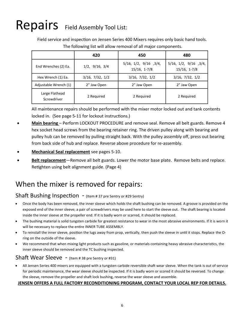
Repairs Field Assembly Tool List:
Field service and inspection on Jensen Series 400 Mixers requires only basic hand tools.
The following list will allow removal of all major components.
All maintenance repairs should be performed with the mixer motor locked out and tank contents
locked in. (See page 5-11 for lockout instructions.)
• Main bearing – Perform LOCKOUT PROCEDURE and remove seal. Remove all belt guards. Remove 4
hex socket head screws from the bearing retainer ring. The driven pulley along with bearing and
pulley hub can be removed by pulling straight back. With the pulley assembly off, press out bearing
from back side of hub and replace. Reverse above procedure for re-assembly.
• Mechanical Seal replacement see pages 5-10.
• Belt replacement—Remove all belt guards. Lower the motor base plate. Remove belts and replace.
Retighten using belt alignment guide. (Page 4)
When the mixer is removed for repairs: Shaft Bushing Inspection - (Item # 37 pre Sentry or #29 Sentry) • Once the body has been removed, the inner sleeve which holds the shaft bushing can be removed. A groove is provided on the
exposed end of the inner sleeve; a pair of screwdrivers may be used here to start the sleeve out. The shaft bearing is located
inside the inner sleeve at the propeller end. If it is badly worn or scarred, it should be replaced.
• The bushing material is solid tungsten carbide for greatest resistance to wear in the most abrasive environments. If it is worn it
will be necessary to replace the entire INNER TUBE ASSEMBLY.
• To reinstall the inner sleeve, position the lugs away from prop, vertically, then push the sleeve in until it stops. Replace the O-
ring on the outside of the sleeve.
• We recommend that when mixing light products such as gasoline, or materials containing heavy abrasive characteristics, the
inner sleeve should be removed and the TC bushing inspected.
Shaft Wear Sleeve - (Item # 38 pre Sentry or #31) • All Jensen Series 400 mixers are equipped with a tungsten carbide reversible shaft wear sleeve. When the tank is out of service
for periodic maintenance, the wear sleeve should be inspected. If it is badly worn or scored it should be reversed. To change
the sleeve, remove the propeller and shaft lock bushing, reverse the wear sleeve and assemble.
JENSEN OFFERS A FULL FACTORY RECONDITIONING PROGRAM, CONTACT YOUR LOCAL REP FOR DETAILS.
420 450 480
End Wrenches (2) Ea. 1/2, 9/16, 3/4 5/16, 1/2, 9/16 ,3/4,
15/16, 1-7/8
5/16, 1/2, 9/16 ,3/4,
15/16, 1-7/8
Hex Wrench (1) Ea. 3/16, 7/32, 1/2 3/16, 7/32, 1/2 3/16, 7/32, 1/2
Adjustable Wrench (1) 2” Jaw Open 2” Jaw Open 2” Jaw Open
Large Flathead
Screwdriver 2 Required 2 Required 2 Required

7
400 (Pre 2014 Sentry System) MECHANICAL SEAL CHANGE
Jensen Serial Numbers before 480 Mixer DR-101 to DR-1123 450 Mixer DO-101 to DO-781

8
Jen
sen
40
0 s
erie
s 2
01
4-O
lder
(P
re-S
entr
y Sy
stem
)
Jen
sen
Ser
ial N
um
ber
s
48
0 M
ixer
DR
-10
1 t
o D
R-1
12
3
45
0 M
ixer
DO
-10
1 t
o D
O-7
81

9

10 S16BR –Rev5 Pg 1 of 2
Jensen Serial Numbers AFTER DR-1123 (480 Mixer) DO-781 (450 Mixer)
1. If tank product is
noticed in one of
the TOP TWO sight
glasses follow the
steps below.
4. Drain RESERVOIR by removing the plug and open the
release VALVE HANDLE. A
5. Remove VENT PLUG in front of the Mixer Bulkhead.
This will accelerate draining the Reservoir tank. B
2. Remove YOKE COVER. (½ OPEN WRENCH)
Remove YOKE bolts. (¾ OPEN WRENCH )
Position YOKE with SEAL PIN HOLE at 12 O'clock Position.
3. Perform Lock-Off by
A. Pulling the YOKE back to stop. (Approximately 1 inch). TANK PRODUCT MAY BLEED DURING THIS OPERATION.
B. Turn YOKE counter-clockwise until SHAFT stops (Approximately 90º). Placing pin at 9 o’clock position.
Mixer will be LOCKED OFF at this point AND CAN BE CONFIRMED BY OPENING THE AIR RELEASE VALVE. (Pg 11.)
6. Remove SHAFT BOLT (¾ OPEN WRENCH ) , YOKE, and KEY
Remove SEAL DRIVE RING. (A solid pull by hand will generally be sufficient.) Two 1/4-20 tapped holes are provided to aid in removal.
MECHANICAL SEAL can normally be reached and replaced at this point. Two 1/4-20 holes have been drilled and tapped into MECHANICAL SEAL Body to aid in removal.
NOTE: Use caution to avoid damage of Lip Seal when removing MECHANICAL SEAL.
• Extreme caution should be taken to not damage the Inner LIP-SEAL, failure will require replacement of LIP-SEAL.
• Reverse steps after installation of new MECHANICAL SEAL. • WARNING: YOU MUST ALIGN SEAL DRIVE RING HOLE WITH SEAL DRIVE PIN. • PERFORM SYSTEM FLUSH OF SENTRY SYSTEM Pg. 11 • If debris is unreachable continue with steps 8-12 SEAL CHAMBER CLEANING.
A.
B.
NOTE: Complete seal exchange can be aided by removal of all covers. TAKE NECESSARY STEPS TO CONTAIN PRODUCT
A
B
2.
3.
6.
4. 5.
7A NOTE;
TOOLS REQUIRED 2” ADJUSTABLE WRENCH
½ OPEN ENDED WRENCH OR SOCKET
¾ OPEN ENDED WRENCH OR SOCKET LARGE FLAT HEAD SCREWDRIVER
Two ¼-20 3”-4” BOLTS

11
9.Partially thread in 1/4-20 bolts (shown with arrows) to aid in turning RETAINING RING with screwdriver.
UNSCREW BY TURNING TO LEFT 4-5 ROTATIONS
10.With RETAINER RING removed Remove foreign matter. Replace LIP SEAL if necessary.
Fluid ports can be checked and cleaned.
11. Install NEW MECHANICAL SEAL noting the stationary pin on SEAL.
8.Locate BEARING LOCK WASHER and pry TAB up clearing the RETAINING RING.
NOTE: TAB may not be in locked the 0º position and may be reinstalled in any of the 8 locking positions.
NOTES AFTER NEW SEAL INSTALLATION: • RETAINER RING is tightened to 1/8 turn after snugged. • Refill lubrication reservoir with 32Oz. of lubrication
fluid. (Royal Purple FDA 46 or similar). SEE SENTRY STARTUP AND FLUSH PROCEDURE. Pg. 11
SEAL CHAMBER CLEANING REMOVE BELT HOUSING COVER
MECHANICAL SEAL stationary pin should be in contact with either anti-rotation pins located at the 3 or 9 O'clock position in the seal chamber.

12
Jensen Sentry System Recharge/Flush Procedure
SYSTEM FLUSH
The purpose of a System Flush is to clean the seal area of debris and other unwanted contaminants that may have collected in the Seal area.
To perform the system flush a containment vessel (bucket) and an adjust-able wrench will be needed. Mixer unit must be powered down.
1) Remove the plug from the Leak Detection Fill Inlet. Item 10
2) Remove the plug from the base of the Valve (Item 7). Place contain-
ment vessel under the Reservoir Valve and raise the valve handle to the open position and empty contents into containment vessel.
3) With valve open, pour FLUSHING fluid into Leak Detection Fill Inlet
(Jensen recommends flushing with the Royal Purple Poly Guard FDA 46) . Add approximately 2-3 quarts and let the system drain.
4) Close Reservoir Valve and replace Inlet plug. Refill Reservoir to cen-
ter of lower sight-glass. Power up mixer for 3-5 minutes.
5) Remove Inlet plug and open Reservoir Valve to drain contents.
Add 2-3 quarts and let the contents drain. Close Reservoir Valve, replace Reservoir Valve plug and fill to center of the lower sight-glass. Replace inlet plug and power up Mixer. This will complete the System Flush.
This will also be the Fill Point for a Sys-tem Flush. A System Flush should be performed at every Lubrication Oil change and every Seal change.
Jensen recommends changing the Seal Lubrication Oil every 6 months. More or Less time between oil change intervals may be possible depending on climate, run time, product, and other factors. Oil quality should be checked monthly.
This is the fill point for adding seal lubrication. FILL WITH : ROYAL PURPLE POLY GUARD FDA 46 (OR COMPARABLE )
Leak Detection Inlet
Removing the pipe plug provides access to
the Seal Cavity and Lubrication Reservoir.
Air Release Valve
MODEL 480 is shown here.
This Valve opens to the “Tank Product Side” of the Sentry System. It is used to “bleed” the Shaft Tube of air and prevent Air Lock during a new installation or if Tank has been lowered below the Shaft Tube. (Removal of pipe plug is necessary.)
NOTE: Model 450 Air Release Valve
and Leak Detection Inlet are swapped left to right. Air Release Valve is pointed in a downward direction.)
Jensen's dual purpose Sentry System is designed to provide lubrication to the Seal area and provide a visual notification of a Seal failure.
Know your system
Upper Leak Detection Glass. If product is visible a leak is present.
Lower Lubrication Level Glass. Fill with lubrication until visible in the center this glass.
*Some models may possess a 3rd port for automated
detection capabilities.
Lubrication Reservoir
Vent\Breather Assembly
Reservoir Drain Valve

13
Fastener Location 420
Bolt Size/Torque
450
Bolt Size/Torque
480
Bolt Size/Torque
Belt Cover 5/16 75 in-lb ⅜ 120 in-lb ⅜ 120 in-lb
Yoke / Hub ½ 30 ft-lb ½ 30 ft-lb ½ 30 ft-lb
Pulley / Hub ½ 30 ft-lb ½ 30 ft-lb
Body / Adapter ½ 30 ft-lb ½ 30 ft-lb ⅝ 70 ft-lb
Yoke & Prop / Shaft ½ 30 ft-lb ½ 30 ft-lb ½ 30 ft-lb
Bearing Retainer / Body 5/16 6ft-lb ⅜ 10 ft-lb 5/16 75 in-lb
TORQUES
1. Oil leakage from belt covers A. Faulty or worn mechanical seal.
B. Faulty O-Ring.
2. Noisy Belts A. Misaligned motor.
B. Oil on belt wearing surface.
C. Loose belt.
3. Vibration
If Vibration above .5 IN/SEC PEAK
LEVELS is observed shut unit
down.
A. Not enough clearance between propeller and tank wall.
B. Bent or damaged propeller blade.
C. Not enough fluid above mixer shaft.
D. Bad main bearing.
E. Worn shaft bearing.
F. Motor running backwards.
G. Diffuser or other inlet pointed toward mixer.
H. Change of Tank fluid conditions.
4. Excessive belt wear A. Check for belt slip or worn pulley.
B. Check for oil or rubber solvent on belt pulleys.
C. Check for heat or chemical fumes. Belt should not get above 140 F. (60 C)
D. Check motor misalignment.
E. Check Belt Tension.
5. Hot electric motor A. Current overload.
B. Bad motor bearing.
C. Change of Tank fluid conditions.
Trouble Shooting Guide

14
Parts & Materials American British German
Cover & Housing
Aluminum Casting 356-T6 ASTM B108 CI. SG70A DIN 1725
Aluminum Casting 319F ASTM B108 CI. SC64D DIN 1725
Body
Iron Casting ASTM A48 CI. 25 DIN 1693
Adapter
Carbon Steel Plate ASTM A283 Gr. D BS.4360 DIN 17100
Round Electric Weld Tube ASTM A500 Gr. B
Weld Filler Rod ASTM A233 Type 7024
Weld Filler Rod ASTM A316 Type 7018
Motor Mount
Carbon Steel Plate ASTM A283 Gr. D BS.4360 DIN17100
Caron Steel Square Type ASTM A500 Gr. B
Weld Filler Rod ASTM A233 Type 24
Mixer Mount
Carbon Steel Plate ASTM A283 Gr.D BS.4360 DIN 17100
Shaft
Stainless Steel Rod ASTM A182
Propeller
Cast Steel ASTM 216 Gr. 70
Weld Filler Rod ASTM A233 Type 7024
Lock Ring & End Bushings
Stainless Steel Type 316SS ASTM A351 Gr. CF8M
Bolts & Nuts ASTM A307
Stainless Steel Gr.2 ASTM A449 DIN 1711
Alloy Steel Gr.5
O-Rings
Viton GFLT ASTM D2000-7B
Spec. AMS 7278
Material Standards
15
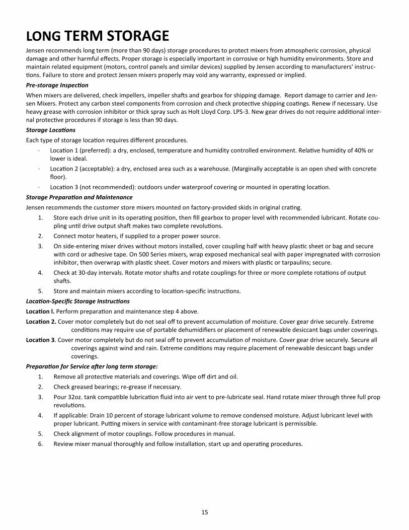
LONG TERM STORAGE Jensen recommends long term (more than 90 days) storage procedures to protect mixers from atmospheric corrosion, physical damage and other harmful effects. Proper storage is especially important in corrosive or high humidity environments. Store and maintain related equipment (motors, control panels and similar devices) supplied by Jensen according to manufacturers' instruc-tions. Failure to store and protect Jensen mixers properly may void any warranty, expressed or implied.
Pre-storage Inspection
When mixers are delivered, check impellers, impeller shafts and gearbox for shipping damage. Report damage to carrier and Jen-sen Mixers. Protect any carbon steel components from corrosion and check protective shipping coatings. Renew if necessary. Use heavy grease with corrosion inhibitor or thick spray such as Holt Lloyd Corp. LPS-3. New gear drives do not require additional inter-nal protective procedures if storage is less than 90 days.
Storage Locations
Each type of storage location requires different procedures.
· Location 1 (preferred): a dry, enclosed, temperature and humidity controlled environment. Relative humidity of 40% or lower is ideal.
· Location 2 (acceptable): a dry, enclosed area such as a warehouse. (Marginally acceptable is an open shed with concrete floor).
· Location 3 (not recommended): outdoors under waterproof covering or mounted in operating location.
Storage Preparation and Maintenance
Jensen recommends the customer store mixers mounted on factory-provided skids in original crating.
1. Store each drive unit in its operating position, then fill gearbox to proper level with recommended lubricant. Rotate cou-pling until drive output shaft makes two complete revolutions.
2. Connect motor heaters, if supplied to a proper power source.
3. On side-entering mixer drives without motors installed, cover coupling half with heavy plastic sheet or bag and secure with cord or adhesive tape. On 500 Series mixers, wrap exposed mechanical seal with paper impregnated with corrosion inhibitor, then overwrap with plastic sheet. Cover motors and mixers with plastic or tarpaulins; secure.
4. Check at 30-day intervals. Rotate motor shafts and rotate couplings for three or more complete rotations of output shafts.
5. Store and maintain mixers according to location-specific instructions.
Location-Specific Storage Instructions
Location l. Perform preparation and maintenance step 4 above.
Location 2. Cover motor completely but do not seal off to prevent accumulation of moisture. Cover gear drive securely. Extreme conditions may require use of portable dehumidifiers or placement of renewable desiccant bags under coverings.
Location 3. Cover motor completely but do not seal off to prevent accumulation of moisture. Cover gear drive securely. Secure all coverings against wind and rain. Extreme conditions may require placement of renewable desiccant bags under coverings.
Preparation for Service after long term storage:
1. Remove all protective materials and coverings. Wipe off dirt and oil.
2. Check greased bearings; re-grease if necessary.
3. Pour 32oz. tank compatible lubrication fluid into air vent to pre-lubricate seal. Hand rotate mixer through three full prop revolutions.
4. If applicable: Drain 10 percent of storage lubricant volume to remove condensed moisture. Adjust lubricant level with proper lubricant. Putting mixers in service with contaminant-free storage lubricant is permissible.
5. Check alignment of motor couplings. Follow procedures in manual.
6. Review mixer manual thoroughly and follow installation, start up and operating procedures.
16
LIMITED WARRANTY Jensen Mixers are warranted against defects in materials or workmanship for a
period of 12 months following date of purchase. This warranty is limited to
replacement or repair of the agitator by Jensen only and does not cover
consequential damages, removal, freight or re-installation. Electric motors are
warranted by their respective manufacturers and are excluded from the Jensen
warranty.
• Jensen will repair or replace, without charge, any part or parts which prove to be
defective, under normal and proper use, within twelve months from the date of
shipment.
• Jensen will not be held liable for any claims or charges for labor and/or parts
resulting from repair or modification of Jensen products without prior written
approval.
• Sub-assemblies installed on Jensen mixers, but not manufactured by Jensen, are
covered by the original manufacturer's guarantee and are excluded from the
guarantee.
• In no case shall Jensen's liability exceed the cost of repair or replacement of the
mixer involved.
• Jensen will supply increased horsepower or additional mixers, without charge,
should any mixer fail to satisfactorily perform the process for which it was
recommended.
• Mixers must be installed and operated in accordance with Jensen's formal
recommendation.
• All pertinent process data must be supplied to Jensen prior to the issuance of a
formal recommendation.
• Recommendations issued by Jensen representatives, or agents, shall not be binding
unless confirmed, in writing, by Jensen.
• It shall be Jensen's prerogative to determine what course of action is most
satisfactory in the event of a claim on the process guarantee.
• The process guarantee shall be valid for twenty-four months following the date of
shipment.
• In no event shall Jensen be liable for special or consequential damages.
• No other guarantees ,express or implied, shall be applicable.
• This guarantee applies only to mixers manufactured after July 1, 1969.

17
NOTES
ATEX NOTES:
• If units are operated in ATEX Zone1 Belts should be checked weekly.
• Maximum RPM430 @ 60Hrz
• Maximum RPM360 @ 50Hrz
• Maximum Torque 680/480 221 Lbs-Ft
• Maximum Torque 450 118 Lbs-Ft
• Caution: Ambient temperature range of -20ºC to 40ºC
• 1a Caution: Units must be operated submerged
• 1b Bearing technical sheets are included in document packet.
• Caution: Bearings have a L10 calculation of 120,000 hours and should be changed based on duty cycle.
• 1c Caution: When operated in Zone 1 gearbox oil level or belt alignment should be checked weekly, otherwise check monthly.
• 1d Caution: Do not allow objects to obstruct the rotation of the propeller
• 2b Caution: Lubrication must be >150C flash point with a weight of 70-90
MIXER
MODEL
MAXIMUM RPM
50Hz/60Hz.
MAX HP
SIZE
HORSEPOWER-
RANGE
MAXIMUM
TORQUE
480 1475/1720 75 40-75HP 221 LBS-FT
450 1475/1720 30 5-30 118 LBS-FT
420 1475/1720 10 5-10 88 LBS-FT
THIS EQUIPMENT HAS BEEN EVALUATED TO THE FOLLOWING STANDARDS.
EN 13463-1: 2009, EN13463-5: 2011
9/2/2016
MOTOR SPECIFICATIONS
MIXER SPECIFICATIONS

18
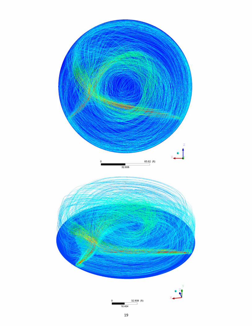
Locating the mixer(s) approximately 15 degrees to the left of the Fill Line compliments mixer performance and encourages product to be pulled into the mixer propeller and quickly dispersed into the tank. NOTE: ALL MIXERS MUST BE SET IN SAME DIRECTION.
Locating the mixer(s) at the opposite side of the Suction Line the allows the user to take advantage of the natural cleaning that will occur due to product being drawn from the tank. NOTE: ALL MIXERS MUST BE SET IN SAME DIRECTION.
Placement for Jensen Mixers
19

20
WWW.JENSENMIXERS.COM