Embed Size (px)
Citation preview

Republic of Kenya Lot 1 –Kenya 132kV Transmission Lines
Kenya Electricity Transmission Company Volume 1 – Section VI - Employer’s
Requirements
Kenya Power Transmission System Improvement Project /PROJECT NO: P- KE-FA0-004 | March 2012
4. SCHEDULES OF TECHNICAL INFORMATION
Kenya Power Transmission System Improvement Project /PROJECT NO: P- KE-FA0-004 March 2012
4.1 132kV OHL PTSIP LOT 1
Republic of Kenya Lot 1 –Kenya 132kV Transmission Lines Kenya Electricity Transmission Company Volume 1 – Section VI - Employer’s Requirements
Kenya Power Transmission System Improvement Project /PROJECT NO: P- KE-FA0-004 March 2012
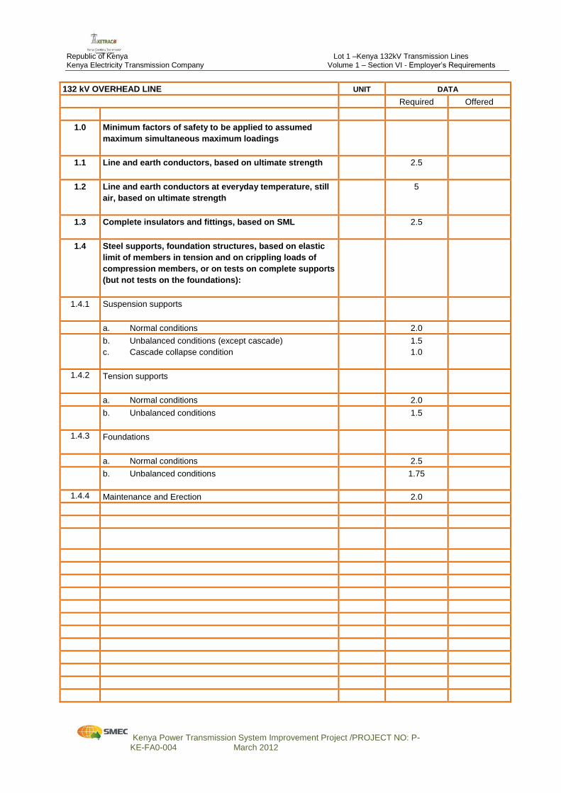
132 kV OVERHEAD LINE UNIT DATA
Required Offered
1.0 Minimum factors of safety to be applied to assumed
maximum simultaneous maximum loadings
1.1 Line and earth conductors, based on ultimate strength
2.5
1.2 Line and earth conductors at everyday temperature, still
air, based on ultimate strength
5
1.3 Complete insulators and fittings, based on SML
2.5
1.4 Steel supports, foundation structures, based on elastic
limit of members in tension and on crippling loads of
compression members, or on tests on complete supports
(but not tests on the foundations):
1.4.1 Suspension supports
a. Normal conditions 2.0
b. Unbalanced conditions (except cascade)
c. Cascade collapse condition
1.5
1.0
1.4.2 Tension supports
a. Normal conditions 2.0
b. Unbalanced conditions
1.5
1.4.3 Foundations
a. Normal conditions 2.5
b. Unbalanced conditions 1.75
1.4.4 Maintenance and Erection 2.0
Republic of Kenya Lot 1 –Kenya 132kV Transmission Lines Kenya Electricity Transmission Company Volume 1 – Section VI - Employer’s Requirements
Kenya Power Transmission System Improvement Project /PROJECT NO: P- KE-FA0-004 March 2012
132 kV OVERHEAD LINE UNIT DATA
Required Offered
132 kV OVERHEAD LINE UNIT DATA
Required Offered
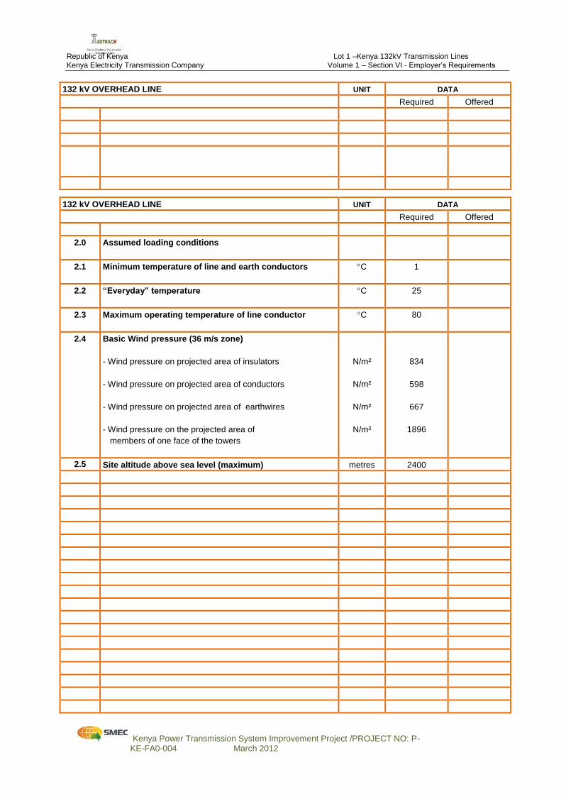
2.0 Assumed loading conditions
2.1 Minimum temperature of line and earth conductors
C 1
2.2 “Everyday” temperature
C 25
2.3 Maximum operating temperature of line conductor
C 80
2.4 Basic Wind pressure (36 m/s zone)
- Wind pressure on projected area of insulators
- Wind pressure on projected area of conductors
- Wind pressure on projected area of earthwires
- Wind pressure on the projected area of
members of one face of the towers
N/m²
N/m²
N/m²
N/m²
834
598
667
1896
2.5 Site altitude above sea level (maximum) metres 2400
Republic of Kenya Lot 1 –Kenya 132kV Transmission Lines Kenya Electricity Transmission Company Volume 1 – Section VI - Employer’s Requirements
Kenya Power Transmission System Improvement Project /PROJECT NO: P- KE-FA0-004 March 2012
132 kV OVERHEAD LINE UNIT DATA
Required Offered
132 kV OVERHEAD LINE UNIT DATA
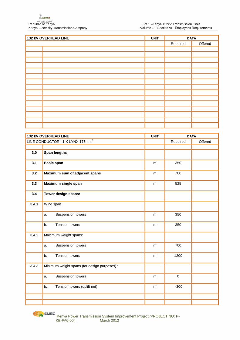
LINE CONDUCTOR: 1 X LYNX 175mm2 Required Offered
3.0 Span lengths
3.1 Basic span
m 350
3.2 Maximum sum of adjacent spans
m 700
3.3 Maximum single span
m 525
3.4 Tower design spans:
3.4.1 Wind span
a. Suspension towers
m 350
b. Tension towers
m 350
3.4.2
Maximum weight spans:
a. Suspension towers
m 700
b. Tension towers
m 1200
3.4.3 Minimum weight spans (for design purposes) :
a. Suspension towers
m 0
b. Tension towers (uplift net)
m -300
Republic of Kenya Lot 1 –Kenya 132kV Transmission Lines Kenya Electricity Transmission Company Volume 1 – Section VI - Employer’s Requirements
Kenya Power Transmission System Improvement Project /PROJECT NO: P- KE-FA0-004 March 2012
132 kV OVERHEAD LINE UNIT DATA
LINE CONDUCTOR: 1 X LYNX 175mm2 Required Offered
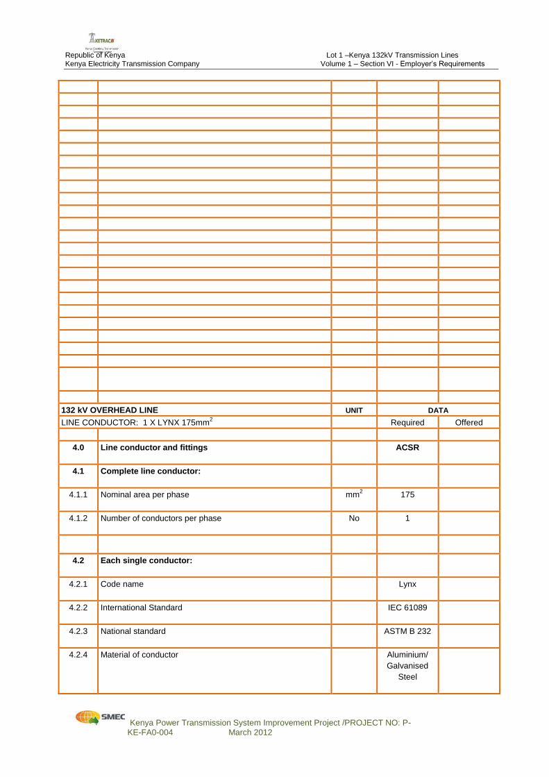
4.0 Line conductor and fittings
ACSR
4.1 Complete line conductor:
4.1.1 Nominal area per phase
mm2
175
4.1.2 Number of conductors per phase
No 1
4.2 Each single conductor:
4.2.1 Code name
Lynx
4.2.2 International Standard
IEC 61089
4.2.3 National standard
ASTM B 232
4.2.4 Material of conductor
Aluminium/
Galvanised
Steel
Republic of Kenya Lot 1 –Kenya 132kV Transmission Lines Kenya Electricity Transmission Company Volume 1 – Section VI - Employer’s Requirements
Kenya Power Transmission System Improvement Project /PROJECT NO: P- KE-FA0-004 March 2012
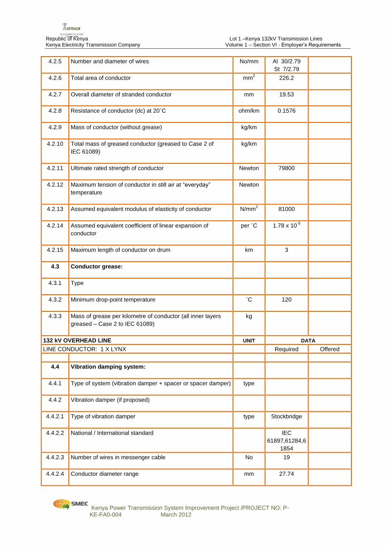
4.2.5 Number and diameter of wires
No/mm Al 30/2.79
St 7/2.79
4.2.6 Total area of conductor
mm2 226.2
4.2.7 Overall diameter of stranded conductor
mm 19.53
4.2.8 Resistance of conductor (dc) at 20˚C
ohm/km 0.1576
4.2.9 Mass of conductor (without grease)
kg/km
4.2.10 Total mass of greased conductor (greased to Case 2 of
IEC 61089)
kg/km
4.2.11 Ultimate rated strength of conductor
Newton 79800
4.2.12 Maximum tension of conductor in still air at “everyday”
temperature
Newton
4.2.13 Assumed equivalent modulus of elasticity of conductor
N/mm2
81000
4.2.14 Assumed equivalent coefficient of linear expansion of
conductor
per ˚C 1.78 x 10⁻⁵
4.2.15 Maximum length of conductor on drum
km 3
4.3 Conductor grease:
4.3.1 Type
4.3.2 Minimum drop-point temperature
˚C 120
4.3.3 Mass of grease per kilometre of conductor (all inner layers
greased – Case 2 to IEC 61089)
kg
132 kV OVERHEAD LINE UNIT DATA
LINE CONDUCTOR: 1 X LYNX Required Offered
4.4 Vibration damping system:
4.4.1 Type of system (vibration damper + spacer or spacer damper)
type
4.4.2 Vibration damper (if proposed)
4.4.2.1 Type of vibration damper
type Stockbridge
4.4.2.2 National / International standard
IEC
61897,61284,6
1854
4.4.2.3 Number of wires in messenger cable
No 19
4.4.2.4 Conductor diameter range
mm 27.74
Republic of Kenya Lot 1 –Kenya 132kV Transmission Lines Kenya Electricity Transmission Company Volume 1 – Section VI - Employer’s Requirements
Kenya Power Transmission System Improvement Project /PROJECT NO: P- KE-FA0-004 March 2012
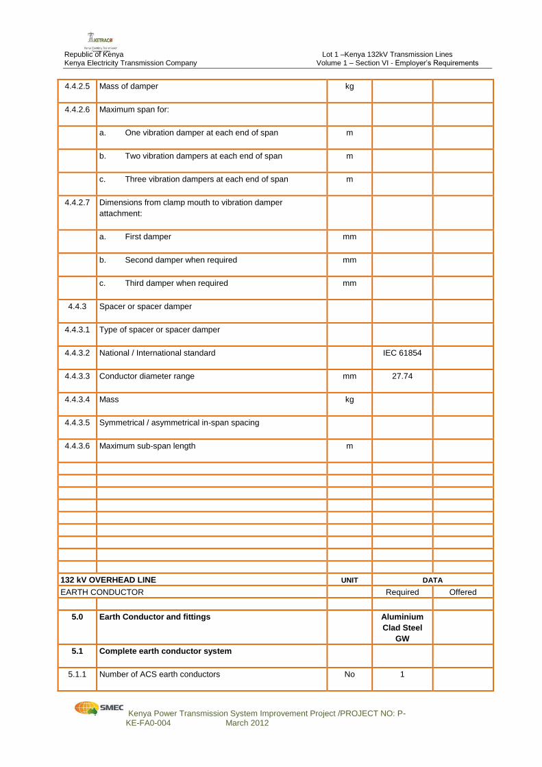
4.4.2.5 Mass of damper
kg
4.4.2.6 Maximum span for:
a. One vibration damper at each end of span
m
b. Two vibration dampers at each end of span
m
c. Three vibration dampers at each end of span
m
4.4.2.7 Dimensions from clamp mouth to vibration damper
attachment:
a. First damper
mm
b. Second damper when required
mm
c. Third damper when required
mm
4.4.3 Spacer or spacer damper
4.4.3.1 Type of spacer or spacer damper
4.4.3.2 National / International standard
IEC 61854
4.4.3.3 Conductor diameter range
mm 27.74
4.4.3.4 Mass
kg
4.4.3.5 Symmetrical / asymmetrical in-span spacing
4.4.3.6 Maximum sub-span length
m
132 kV OVERHEAD LINE UNIT DATA
EARTH CONDUCTOR Required Offered
5.0 Earth Conductor and fittings
Aluminium
Clad Steel
GW
5.1 Complete earth conductor system
5.1.1 Number of ACS earth conductors
No 1
Republic of Kenya Lot 1 –Kenya 132kV Transmission Lines Kenya Electricity Transmission Company Volume 1 – Section VI - Employer’s Requirements
Kenya Power Transmission System Improvement Project /PROJECT NO: P- KE-FA0-004 March 2012
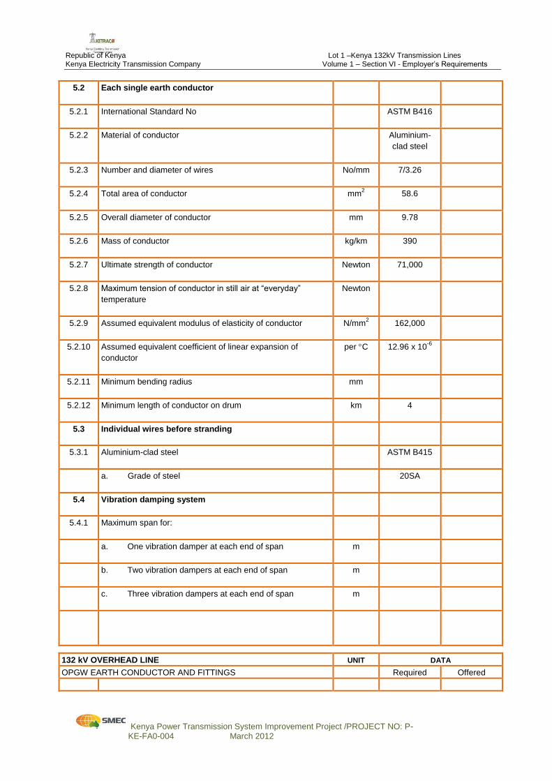
5.2 Each single earth conductor
5.2.1 International Standard No
ASTM B416
5.2.2 Material of conductor
Aluminium-
clad steel
5.2.3 Number and diameter of wires
No/mm 7/3.26
5.2.4 Total area of conductor
mm2 58.6
5.2.5 Overall diameter of conductor
mm 9.78
5.2.6 Mass of conductor
kg/km 390
5.2.7 Ultimate strength of conductor
Newton 71,000
5.2.8 Maximum tension of conductor in still air at “everyday”
temperature
Newton
5.2.9 Assumed equivalent modulus of elasticity of conductor
N/mm2 162,000
5.2.10 Assumed equivalent coefficient of linear expansion of
conductor
per C 12.96 x 10⁻⁶
5.2.11 Minimum bending radius
mm
5.2.12 Minimum length of conductor on drum
km 4
5.3 Individual wires before stranding
5.3.1 Aluminium-clad steel
ASTM B415
a. Grade of steel
20SA
5.4 Vibration damping system
5.4.1 Maximum span for:
a. One vibration damper at each end of span
m
b. Two vibration dampers at each end of span
m
c. Three vibration dampers at each end of span
m
132 kV OVERHEAD LINE UNIT DATA
OPGW EARTH CONDUCTOR AND FITTINGS Required Offered
Republic of Kenya Lot 1 –Kenya 132kV Transmission Lines Kenya Electricity Transmission Company Volume 1 – Section VI - Employer’s Requirements
Kenya Power Transmission System Improvement Project /PROJECT NO: P- KE-FA0-004 March 2012
132 kV OVERHEAD LINE UNIT DATA
OPGW EARTH CONDUCTOR AND FITTINGS Required Offered
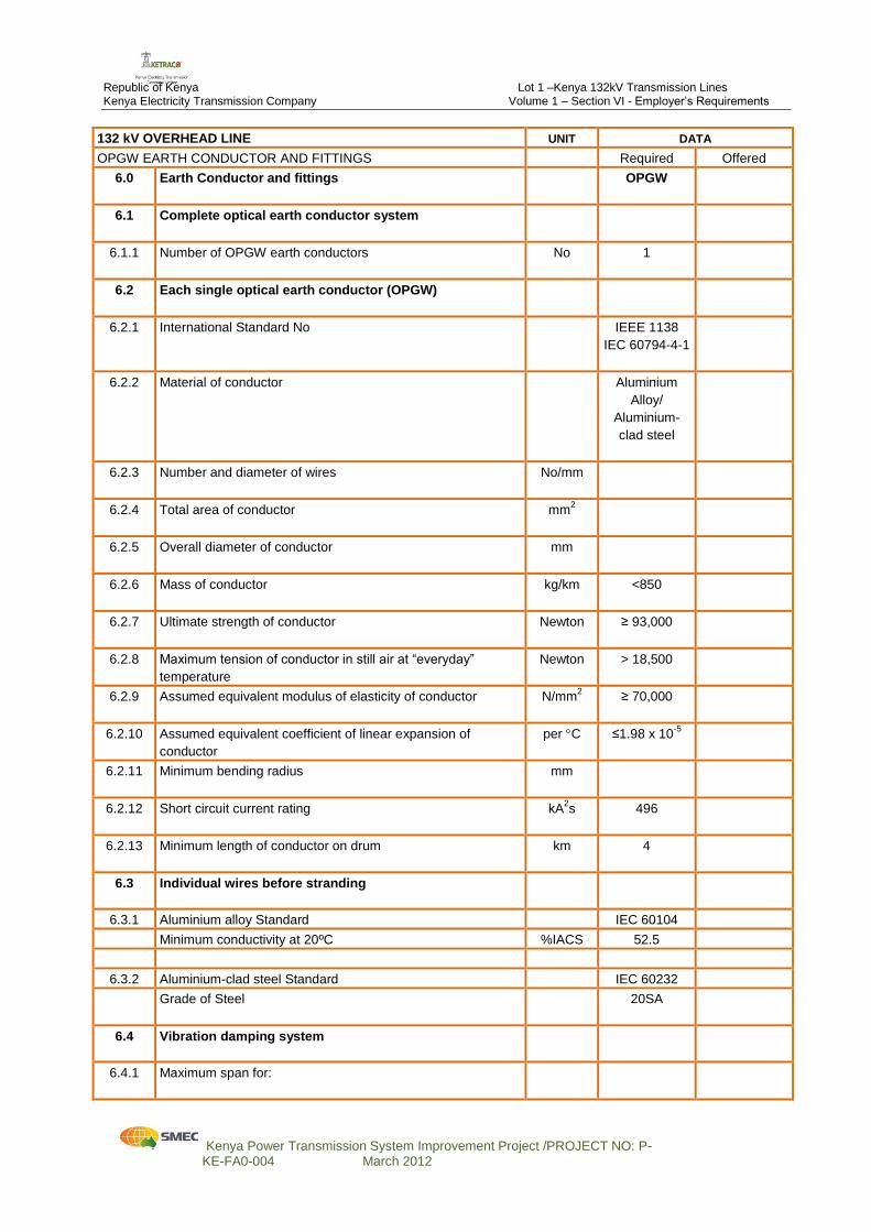
6.0 Earth Conductor and fittings
OPGW
6.1 Complete optical earth conductor system
6.1.1 Number of OPGW earth conductors
No 1
6.2 Each single optical earth conductor (OPGW)
6.2.1 International Standard No
IEEE 1138
IEC 60794-4-1
6.2.2 Material of conductor
Aluminium
Alloy/
Aluminium-
clad steel
6.2.3 Number and diameter of wires
No/mm
6.2.4 Total area of conductor
mm2
6.2.5 Overall diameter of conductor
mm
6.2.6 Mass of conductor
kg/km <850
6.2.7 Ultimate strength of conductor
Newton ≥ 93,000
6.2.8 Maximum tension of conductor in still air at “everyday”
temperature
Newton > 18,500
6.2.9 Assumed equivalent modulus of elasticity of conductor
N/mm2 ≥ 70,000
6.2.10 Assumed equivalent coefficient of linear expansion of
conductor
per C ≤1.98 x 10⁻⁵
6.2.11 Minimum bending radius
mm
6.2.12 Short circuit current rating
kA2s 496
6.2.13 Minimum length of conductor on drum
km 4
6.3 Individual wires before stranding
6.3.1 Aluminium alloy Standard IEC 60104
Minimum conductivity at 20ºC %IACS 52.5
6.3.2 Aluminium-clad steel Standard IEC 60232
Grade of Steel
20SA
6.4 Vibration damping system
6.4.1 Maximum span for:
Republic of Kenya Lot 1 –Kenya 132kV Transmission Lines Kenya Electricity Transmission Company Volume 1 – Section VI - Employer’s Requirements
Kenya Power Transmission System Improvement Project /PROJECT NO: P- KE-FA0-004 March 2012
132 kV OVERHEAD LINE UNIT DATA
OPGW EARTH CONDUCTOR AND FITTINGS Required Offered
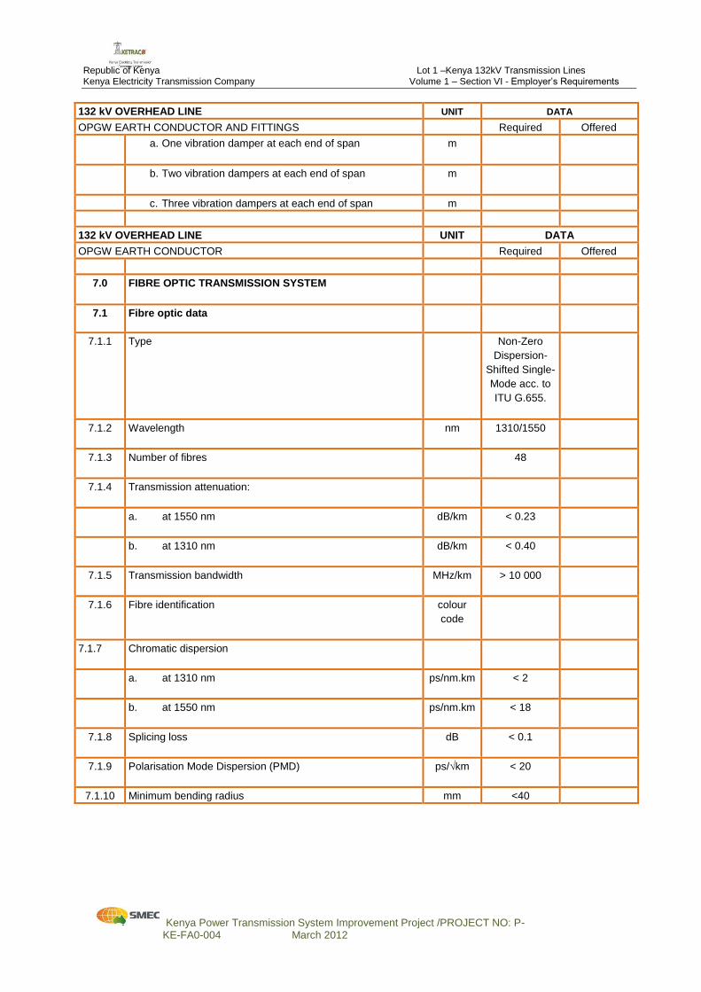
a. One vibration damper at each end of span
m
b. Two vibration dampers at each end of span
m
c. Three vibration dampers at each end of span m
132 kV OVERHEAD LINE UNIT DATA
OPGW EARTH CONDUCTOR Required Offered
7.0 FIBRE OPTIC TRANSMISSION SYSTEM
7.1 Fibre optic data
7.1.1 Type
Non-Zero
Dispersion-
Shifted Single-
Mode acc. to
ITU G.655.
7.1.2 Wavelength
nm 1310/1550
7.1.3 Number of fibres
48
7.1.4 Transmission attenuation:
a. at 1550 nm
dB/km < 0.23
b. at 1310 nm
dB/km < 0.40
7.1.5 Transmission bandwidth
MHz/km > 10 000
7.1.6 Fibre identification colour
code
7.1.7 Chromatic dispersion
a. at 1310 nm
ps/nm.km < 2
b. at 1550 nm
ps/nm.km < 18
7.1.8 Splicing loss
dB < 0.1
7.1.9 Polarisation Mode Dispersion (PMD)
ps/√km < 20
7.1.10 Minimum bending radius mm <40
Republic of Kenya Lot 1 –Kenya 132kV Transmission Lines Kenya Electricity Transmission Company Volume 1 – Section VI - Employer’s Requirements
Kenya Power Transmission System Improvement Project /PROJECT NO: P- KE-FA0-004 March 2012
132 kV OVERHEAD LINE UNIT DATA
OPGW EARTH CONDUCTOR AND FITTINGS Required Offered
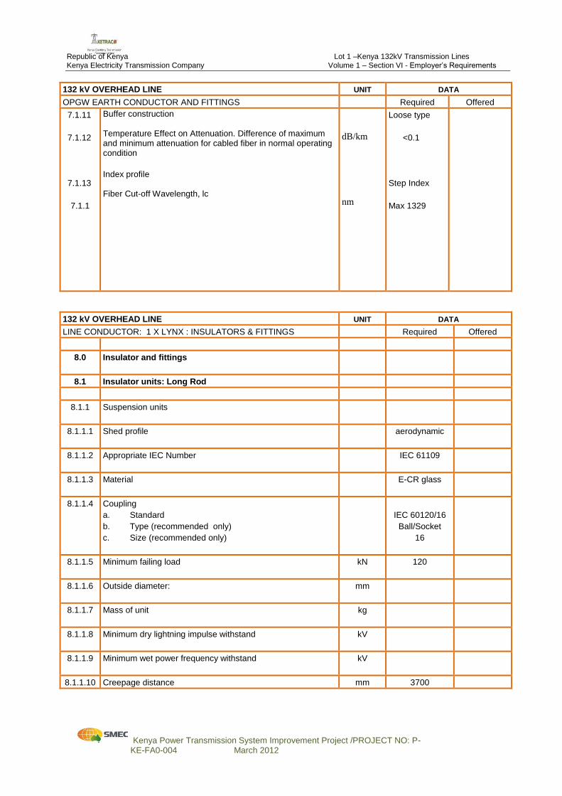
7.1.11
7.1.12
7.1.13
7.1.1
Buffer construction Temperature Effect on Attenuation. Difference of maximum and minimum attenuation for cabled fiber in normal operating condition
Index profile Fiber Cut-off Wavelength, lc
dB/km
nm
Loose type
<0.1
Step Index
Max 1329
132 kV OVERHEAD LINE UNIT DATA
LINE CONDUCTOR: 1 X LYNX : INSULATORS & FITTINGS Required Offered
8.0 Insulator and fittings
8.1 Insulator units: Long Rod
8.1.1 Suspension units
8.1.1.1 Shed profile
aerodynamic
8.1.1.2 Appropriate IEC Number
IEC 61109
8.1.1.3 Material
E-CR glass
8.1.1.4
Coupling
a. Standard
b. Type (recommended only)
c. Size (recommended only)
IEC 60120/16
Ball/Socket
16
8.1.1.5 Minimum failing load
kN 120
8.1.1.6 Outside diameter:
mm
8.1.1.7 Mass of unit
kg
8.1.1.8 Minimum dry lightning impulse withstand
kV
8.1.1.9 Minimum wet power frequency withstand
kV
8.1.1.10 Creepage distance mm 3700
Republic of Kenya Lot 1 –Kenya 132kV Transmission Lines Kenya Electricity Transmission Company Volume 1 – Section VI - Employer’s Requirements
Kenya Power Transmission System Improvement Project /PROJECT NO: P- KE-FA0-004 March 2012
132 kV OVERHEAD LINE UNIT DATA
LINE CONDUCTOR: 1 X LYNX : INSULATORS & FITTINGS Required Offered
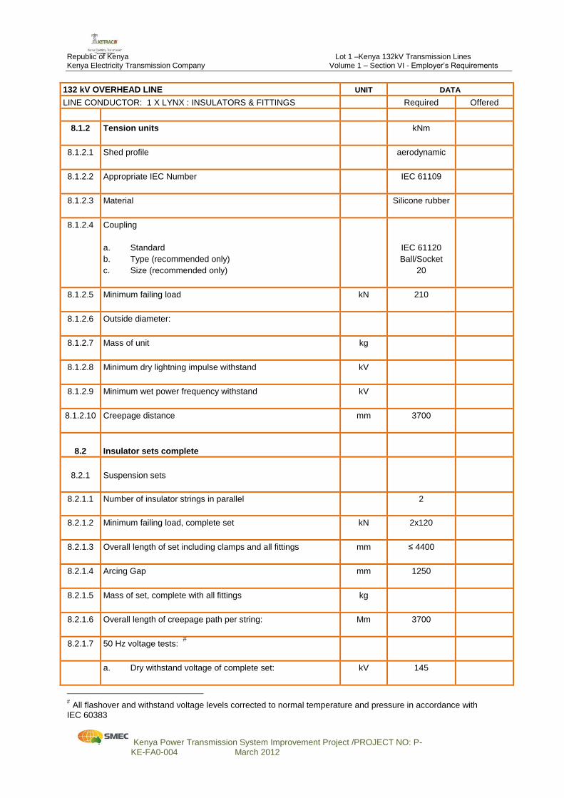
8.1.2 Tension units
kNm
8.1.2.1 Shed profile
aerodynamic
8.1.2.2 Appropriate IEC Number
IEC 61109
8.1.2.3 Material
Silicone rubber
8.1.2.4 Coupling
a. Standard
b. Type (recommended only)
c. Size (recommended only)
IEC 61120
Ball/Socket
20
8.1.2.5 Minimum failing load
kN 210
8.1.2.6 Outside diameter:
8.1.2.7 Mass of unit
kg
8.1.2.8 Minimum dry lightning impulse withstand
kV
8.1.2.9 Minimum wet power frequency withstand
kV
8.1.2.10 Creepage distance
mm 3700
8.2
Insulator sets complete
8.2.1
Suspension sets
8.2.1.1 Number of insulator strings in parallel
2
8.2.1.2 Minimum failing load, complete set
kN 2x120
8.2.1.3 Overall length of set including clamps and all fittings
mm ≤ 4400
8.2.1.4 Arcing Gap
mm 1250
8.2.1.5 Mass of set, complete with all fittings
kg
8.2.1.6 Overall length of creepage path per string:
Mm 3700
8.2.1.7 50 Hz voltage tests:
a. Dry withstand voltage of complete set:
kV 145
All flashover and withstand voltage levels corrected to normal temperature and pressure in accordance with
IEC 60383
Republic of Kenya Lot 1 –Kenya 132kV Transmission Lines Kenya Electricity Transmission Company Volume 1 – Section VI - Employer’s Requirements
Kenya Power Transmission System Improvement Project /PROJECT NO: P- KE-FA0-004 March 2012
132 kV OVERHEAD LINE UNIT DATA
LINE CONDUCTOR: 1 X LYNX : INSULATORS & FITTINGS Required Offered
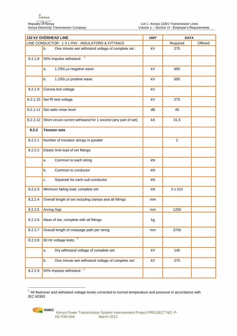
b. One minute wet withstand voltage of complete set :
kV 275
8.2.1.8 50% Impulse withstand:
a. 1.2/50 s negative wave:
kV 650
b. 1.2/50 s positive wave:
kV 650
8.2.1.9 Corona test voltage
kV
8.2.1.10 Set RI test voltage
kV 275
8.2.1.11 Set radio noise level
dB 45
8.2.2.12
Short circuit current withstand for 1 second (any part of set) kA 31.5
8.2.2 Tension sets
8.2.2.1 Number of insulator strings in parallel
2
8.2.2.2 Elastic limit load of set fittings:
a. Common to each string
kN
b. Common to conductor
kN
c. Separate for each sub-conductor
kN
8.2.2.3 Minimum failing load, complete set
kN 2 x 210
8.2.2.4 Overall length of set including clamps and all fittings
mm
8.2.2.5 Arcing Gap mm 1250
8.2.2.6
Mass of set, complete with all fittings
kg
8.2.2.7 Overall length of creepage path per string:
mm 3700
8.2.2.8 50 Hz voltage tests:
a. Dry withstand voltage of complete set:
kV 145
b. One minute wet withstand voltage of complete set:
kV 275
8.2.2.9 50% Impulse withstand:
All flashover and withstand voltage levels corrected to normal temperature and pressure in accordance with
IEC 60383
Republic of Kenya Lot 1 –Kenya 132kV Transmission Lines Kenya Electricity Transmission Company Volume 1 – Section VI - Employer’s Requirements
Kenya Power Transmission System Improvement Project /PROJECT NO: P- KE-FA0-004 March 2012
132 kV OVERHEAD LINE UNIT DATA
LINE CONDUCTOR: 1 X LYNX : INSULATORS & FITTINGS Required Offered
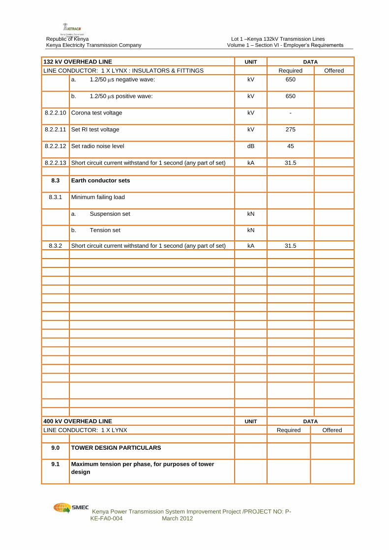
a. 1.2/50 s negative wave:
kV 650
b. 1.2/50 s positive wave:
kV 650
8.2.2.10 Corona test voltage
kV -
8.2.2.11 Set RI test voltage
kV 275
8.2.2.12 Set radio noise level
dB 45
8.2.2.13 Short circuit current withstand for 1 second (any part of set) kA 31.5
8.3 Earth conductor sets
8.3.1 Minimum failing load
a. Suspension set
kN
b. Tension set
kN
8.3.2 Short circuit current withstand for 1 second (any part of set) kA 31.5
400 kV OVERHEAD LINE UNIT DATA
LINE CONDUCTOR: 1 X LYNX Required Offered
9.0 TOWER DESIGN PARTICULARS
9.1 Maximum tension per phase, for purposes of tower
design

Republic of Kenya Lot 1 –Kenya 132kV Transmission Lines Kenya Electricity Transmission Company Volume 1 – Section VI - Employer’s Requirements
Kenya Power Transmission System Improvement Project /PROJECT NO: P- KE-FA0-004 March 2012
132 kV OVERHEAD LINE UNIT DATA
LINE CONDUCTOR: 1 X LYNX : INSULATORS & FITTINGS Required Offered
a. Suspension towers
Newton
b. Tension towers
Newton
c. Downleads per conductor bundle
Newton
9.1.1 Maximum tension per earth conductor for purpose of tower
design and application: ACS Earthwire
a. Suspension towers
Newton
b. Tension towers
Newton
c. Earth conductor downleads
Newton
9.1.2 Maximum tension per earth conductor for purpose of tower
design and application: OPGW
a. Suspension towers
Newton
b. Tension towers
Newton
c. OPGW downleads
Newton
9.2 Minimum clearance between live metal and tower
steelwork:-
a. with suspension insulator set swing, at 65º
mm 1100
b. with suspension insulator set swing, 0 - 10º
mm 3100
c. with suspension insulator set swing 10 - 35º
mm 1800
9.3 Minimum clearance to steelwork on which a man may
stand for live line maintenance (crossarm floor)
m 5.0
9.4 Downleads – minimum clearances:
a. phase to phase clearance in still air
mm 4400
b. phase to phase clearance under conditions of
maximum (opposing) swing and sag
mm 3700
9.5 Earth conductor suspension clamps, unobstructed
transverse swing angle from vertical
degrees 0 – 50
9.6 Earth conductor maximum shielding angle from vertical
at tower attachment point over outer line conductors
degrees 17
Republic of Kenya Lot 1 –Kenya 132kV Transmission Lines Kenya Electricity Transmission Company Volume 1 – Section VI - Employer’s Requirements
Kenya Power Transmission System Improvement Project /PROJECT NO: P- KE-FA0-004 March 2012
132 kV OVERHEAD LINE UNIT DATA
LINE CONDUCTOR: 1 X LYNX : INSULATORS & FITTINGS Required Offered
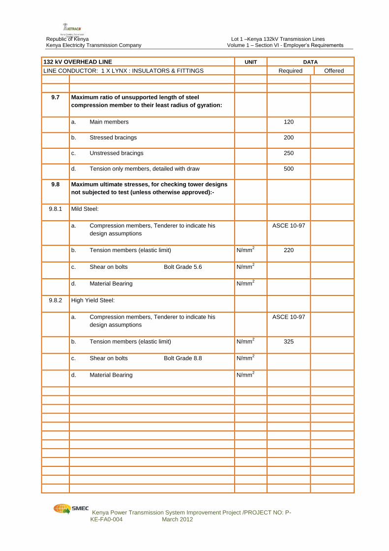
9.7 Maximum ratio of unsupported length of steel
compression member to their least radius of gyration:
a. Main members
120
b. Stressed bracings
200
c. Unstressed bracings
250
d. Tension only members, detailed with draw
500
9.8 Maximum ultimate stresses, for checking tower designs
not subjected to test (unless otherwise approved):-
9.8.1 Mild Steel:
a. Compression members, Tenderer to indicate his
design assumptions
ASCE 10-97
b. Tension members (elastic limit)
N/mm2 220
c. Shear on bolts Bolt Grade 5.6
N/mm2
d. Material Bearing
N/mm2
9.8.2 High Yield Steel:
a. Compression members, Tenderer to indicate his
design assumptions
ASCE 10-97
b. Tension members (elastic limit)
N/mm2 325
c. Shear on bolts Bolt Grade 8.8
N/mm2
d. Material Bearing
N/mm2
Republic of Kenya Lot 1 –Kenya 132kV Transmission Lines Kenya Electricity Transmission Company Volume 1 – Section VI - Employer’s Requirements
Kenya Power Transmission System Improvement Project /PROJECT NO: P- KE-FA0-004 March 2012
132 kV OVERHEAD LINE UNIT DATA
LINE CONDUCTOR: 1 X LYNX : INSULATORS & FITTINGS Required Offered
132 kV OVERHEAD LINE UNIT DATA
LINE CONDUCTOR: 1 X LYNX Required Offered
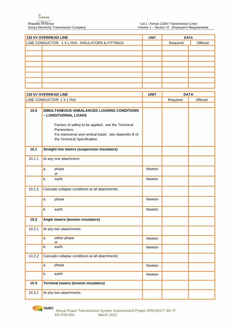
10.0 SIMULTANEOUS UNBALANCED LOADING CONDITIONS
– LONGITUDINAL LOADS
Factors of safety to be applied: see the Technical
Parameters.
For transverse and vertical loads: see Appendix B of
the Technical Specification.
10.1 Straight line towers (suspension insulators)
10.1.1 At any one attachment:
a. phase
or
Newton
b. earth
Newton
10.1.2 Cascade collapse conditions at all attachments:
a. phase
Newton
b. earth
Newton
10.2 Angle towers (tension insulators)
10.2.1 At any two attachments:
a. either phase or
Newton
b. earth
Newton
10.2.2 Cascade collapse conditions at all attachments:
a. phase
Newton
b. earth
Newton
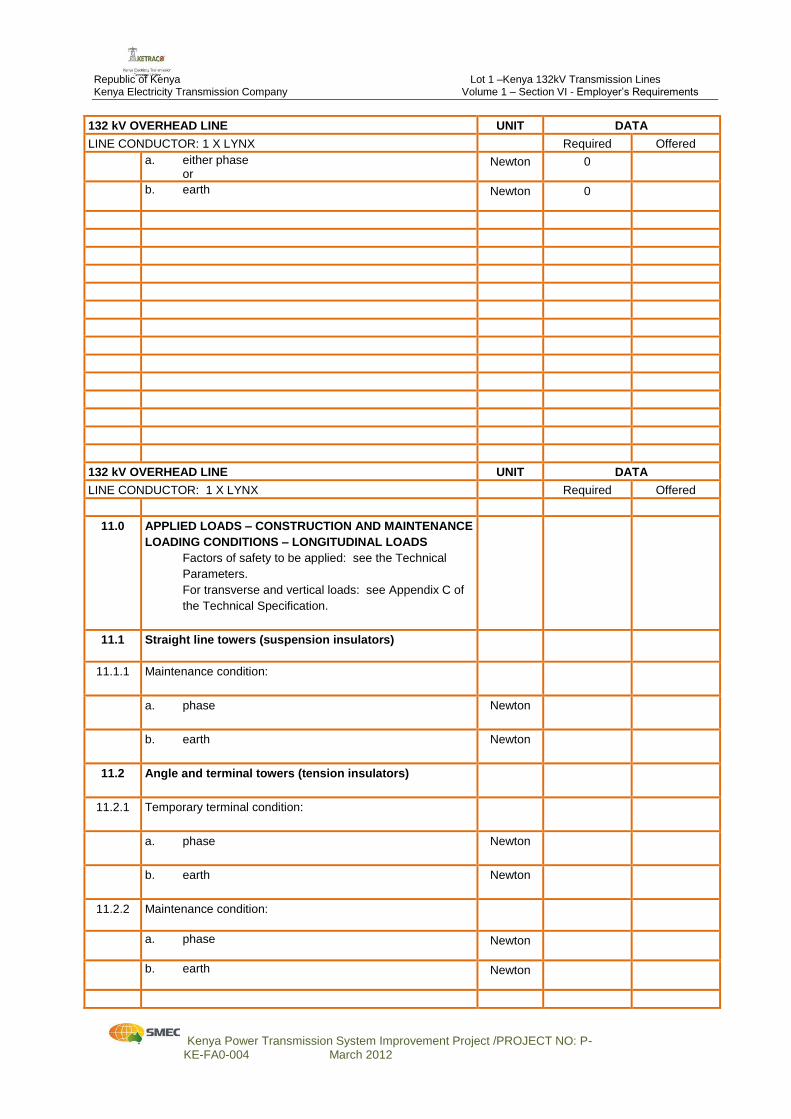
10.3 Terminal towers (tension insulators)
10.3.1 At any two attachments:
Republic of Kenya Lot 1 –Kenya 132kV Transmission Lines Kenya Electricity Transmission Company Volume 1 – Section VI - Employer’s Requirements
Kenya Power Transmission System Improvement Project /PROJECT NO: P- KE-FA0-004 March 2012
132 kV OVERHEAD LINE UNIT DATA
LINE CONDUCTOR: 1 X LYNX Required Offered
a. either phase or
Newton 0
b. earth
Newton 0
132 kV OVERHEAD LINE UNIT DATA
LINE CONDUCTOR: 1 X LYNX Required Offered
11.0 APPLIED LOADS – CONSTRUCTION AND MAINTENANCE
LOADING CONDITIONS – LONGITUDINAL LOADS
Factors of safety to be applied: see the Technical
Parameters.
For transverse and vertical loads: see Appendix C of
the Technical Specification.
11.1 Straight line towers (suspension insulators)
11.1.1 Maintenance condition:
a. phase
Newton
b. earth
Newton
11.2 Angle and terminal towers (tension insulators)
11.2.1
Temporary terminal condition:
a. phase
Newton
b. earth
Newton
11.2.2 Maintenance condition:
a. phase
Newton
b. earth
Newton
Republic of Kenya Lot 1 –Kenya 132kV Transmission Lines Kenya Electricity Transmission Company Volume 1 – Section VI - Employer’s Requirements
Kenya Power Transmission System Improvement Project /PROJECT NO: P- KE-FA0-004 March 2012
132 kV OVERHEAD LINE UNIT DATA
LINE CONDUCTOR: 1 X LYNX Required Offered
132 kV OVERHEAD LINE UNIT DATA
LINE CONDUCTOR: 1 X LYNX Required Offered
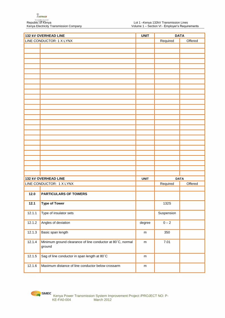
12.0 PARTICULARS OF TOWERS
12.1 Type of Tower
132S
12.1.1 Type of insulator sets
Suspension
12.1.2 Angles of deviation
degree 0 – 2
12.1.3 Basic span length
m 350
12.1.4 Minimum ground clearance of line conductor at 80˚C, normal
ground
m 7.01
12.1.5 Sag of line conductor in span length at 80˚C
m
12.1.6 Maximum distance of line conductor below crossarm
m
Republic of Kenya Lot 1 –Kenya 132kV Transmission Lines Kenya Electricity Transmission Company Volume 1 – Section VI - Employer’s Requirements
Kenya Power Transmission System Improvement Project /PROJECT NO: P- KE-FA0-004 March 2012
132 kV OVERHEAD LINE UNIT DATA
LINE CONDUCTOR: 1 X LYNX Required Offered
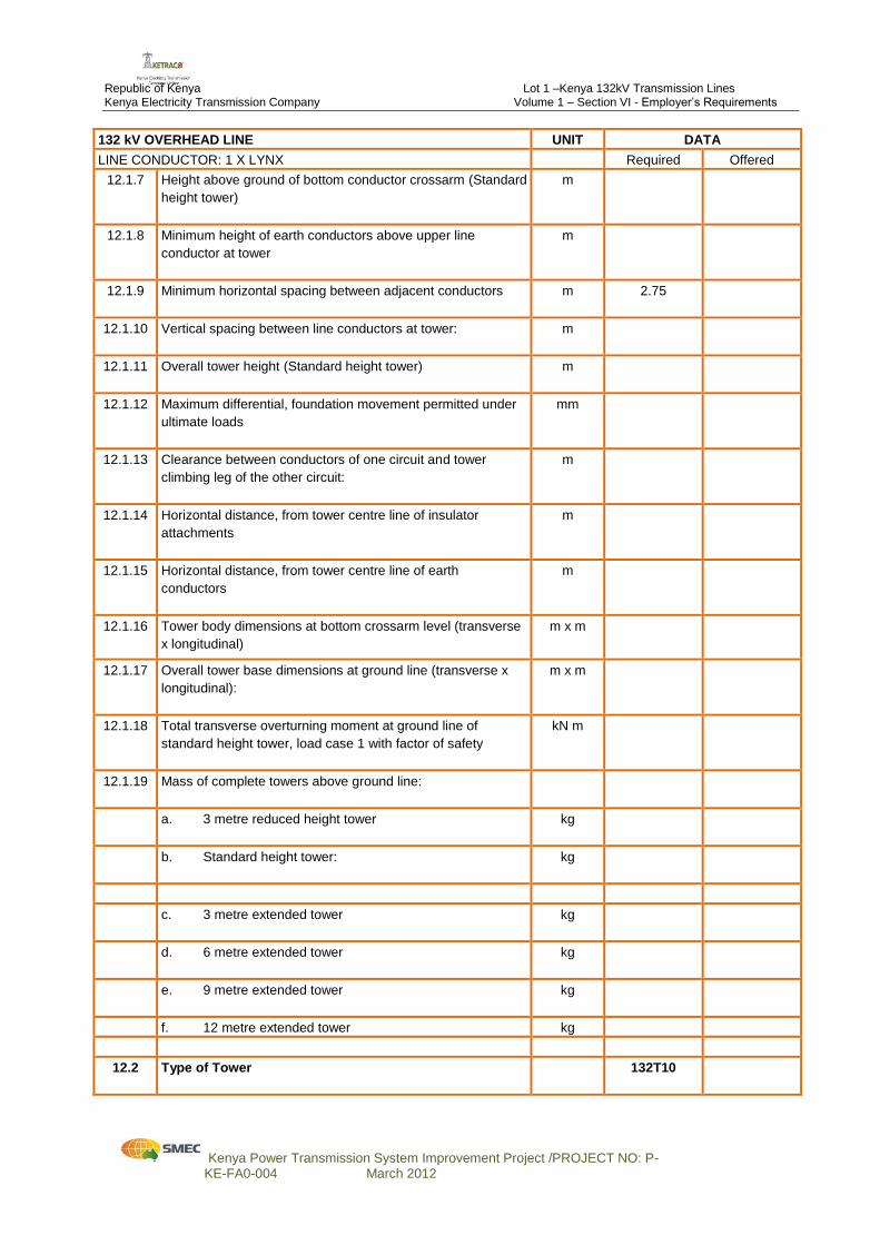
12.1.7 Height above ground of bottom conductor crossarm (Standard
height tower)
m
12.1.8 Minimum height of earth conductors above upper line
conductor at tower
m
12.1.9 Minimum horizontal spacing between adjacent conductors
m 2.75
12.1.10 Vertical spacing between line conductors at tower:
m
12.1.11 Overall tower height (Standard height tower)
m
12.1.12 Maximum differential, foundation movement permitted under
ultimate loads
mm
12.1.13 Clearance between conductors of one circuit and tower
climbing leg of the other circuit:
m
12.1.14 Horizontal distance, from tower centre line of insulator
attachments
m
12.1.15 Horizontal distance, from tower centre line of earth
conductors
m
12.1.16 Tower body dimensions at bottom crossarm level (transverse
x longitudinal)
m x m
12.1.17 Overall tower base dimensions at ground line (transverse x
longitudinal):
m x m
12.1.18 Total transverse overturning moment at ground line of
standard height tower, load case 1 with factor of safety
kN m
12.1.19 Mass of complete towers above ground line:
a. 3 metre reduced height tower
kg
b. Standard height tower:
kg
c. 3 metre extended tower
kg
d. 6 metre extended tower
kg
e. 9 metre extended tower
kg
f. 12 metre extended tower kg
12.2 Type of Tower
132T10

Republic of Kenya Lot 1 –Kenya 132kV Transmission Lines Kenya Electricity Transmission Company Volume 1 – Section VI - Employer’s Requirements
Kenya Power Transmission System Improvement Project /PROJECT NO: P- KE-FA0-004 March 2012
132 kV OVERHEAD LINE UNIT DATA
LINE CONDUCTOR: 1 X LYNX Required Offered
12.2.1 Type of insulator set
Tension
12.2.2 Angles of deviation
degree 0 – 10
12.2.3 Basic span length
m
12.2.4 Minimum ground clearance of line conductor at 80˚C, normal
ground
m
12.2.5 Sag of line conductor in span length at 80˚C
m
12.2.6 Maximum distance of line conductor below crossarm
m
12.2.7 Height above ground of bottom conductor crossarm
m
12.2.8 Minimum height of earth conductors above upper line
conductor at tower
m
12.2.9 Minimum horizontal spacing between adjacent conductors
m
12.2.10 Vertical spacing between line conductors at tower:
m
12.2.11 Overall tower height
m
12.2.12 Maximum differential, foundation movement permitted under
ultimate loads
mm
12.2.13 Clearance between conductors of one circuit and tower
climbing leg of the other circuit:
m
12.2.14 Horizontal distance, from tower centre line of insulator
attachments
m
12.2.15 Horizontal distance, from tower centre line of earth
conductors
m
12.2.16 Tower body dimensions at bottom crossarm level (transverse
x longitudinal)
m x m
12.2.17
Overall tower base dimensions at ground line (transverse x
longitudinal):
m x m
Republic of Kenya Lot 1 –Kenya 132kV Transmission Lines Kenya Electricity Transmission Company Volume 1 – Section VI - Employer’s Requirements
Kenya Power Transmission System Improvement Project /PROJECT NO: P- KE-FA0-004 March 2012
132 kV OVERHEAD LINE UNIT DATA
LINE CONDUCTOR: 1 X LYNX Required Offered
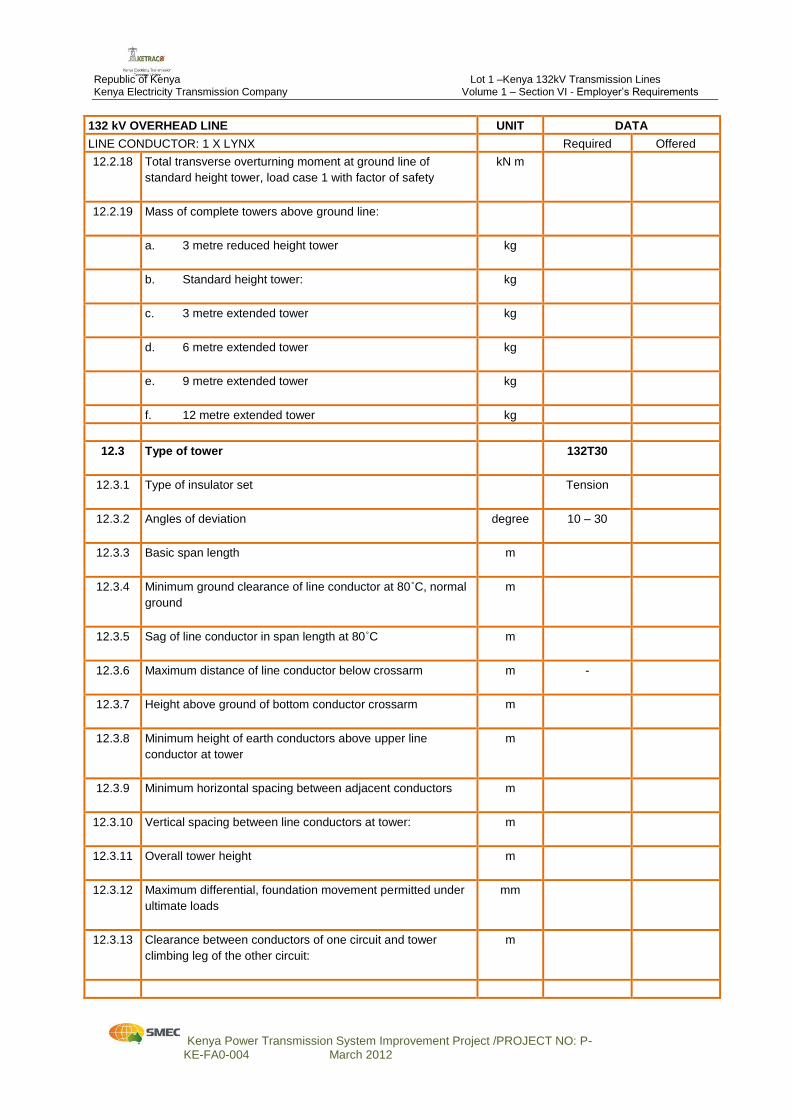
12.2.18 Total transverse overturning moment at ground line of
standard height tower, load case 1 with factor of safety
kN m
12.2.19 Mass of complete towers above ground line:
a. 3 metre reduced height tower
kg
b. Standard height tower:
kg
c. 3 metre extended tower
kg
d. 6 metre extended tower
kg
e. 9 metre extended tower
kg
f. 12 metre extended tower kg
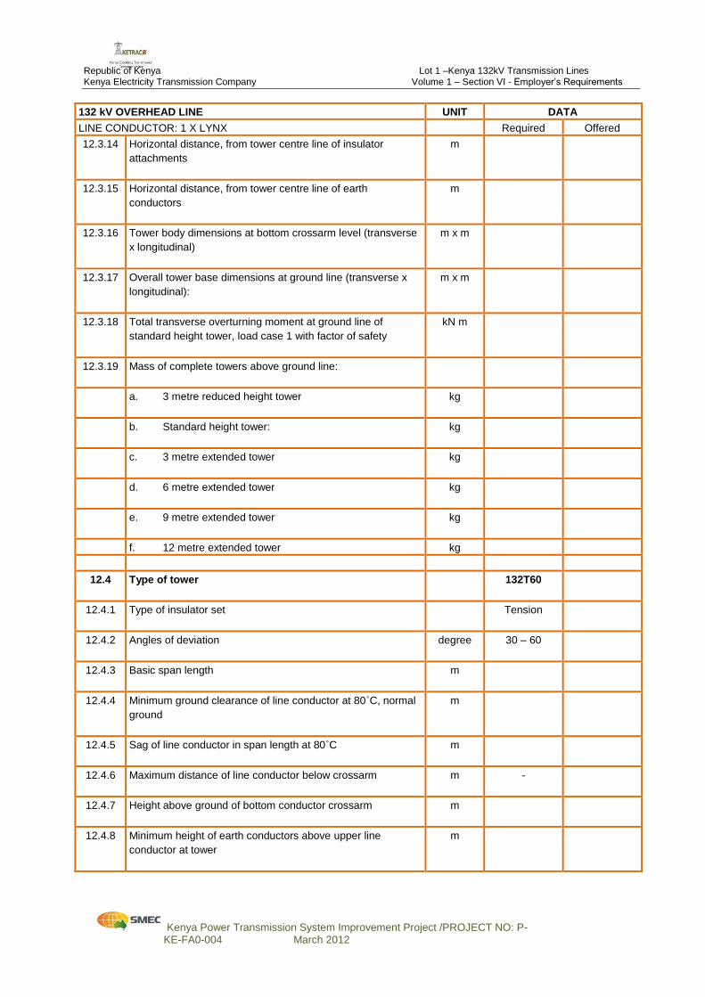
12.3 Type of tower
132T30
12.3.1 Type of insulator set
Tension
12.3.2 Angles of deviation
degree 10 – 30
12.3.3 Basic span length
m
12.3.4 Minimum ground clearance of line conductor at 80˚C, normal
ground
m
12.3.5 Sag of line conductor in span length at 80˚C
m
12.3.6 Maximum distance of line conductor below crossarm
m -
12.3.7 Height above ground of bottom conductor crossarm
m
12.3.8 Minimum height of earth conductors above upper line
conductor at tower
m
12.3.9 Minimum horizontal spacing between adjacent conductors
m
12.3.10 Vertical spacing between line conductors at tower:
m
12.3.11 Overall tower height
m
12.3.12 Maximum differential, foundation movement permitted under
ultimate loads
mm
12.3.13 Clearance between conductors of one circuit and tower
climbing leg of the other circuit:
m
Republic of Kenya Lot 1 –Kenya 132kV Transmission Lines Kenya Electricity Transmission Company Volume 1 – Section VI - Employer’s Requirements
Kenya Power Transmission System Improvement Project /PROJECT NO: P- KE-FA0-004 March 2012
132 kV OVERHEAD LINE UNIT DATA
LINE CONDUCTOR: 1 X LYNX Required Offered
12.3.14 Horizontal distance, from tower centre line of insulator
attachments
m
12.3.15 Horizontal distance, from tower centre line of earth
conductors
m
12.3.16 Tower body dimensions at bottom crossarm level (transverse
x longitudinal)
m x m
12.3.17 Overall tower base dimensions at ground line (transverse x
longitudinal):
m x m
12.3.18 Total transverse overturning moment at ground line of
standard height tower, load case 1 with factor of safety
kN m
12.3.19 Mass of complete towers above ground line:
a. 3 metre reduced height tower
kg
b. Standard height tower:
kg
c. 3 metre extended tower
kg
d. 6 metre extended tower
kg
e. 9 metre extended tower
kg
f. 12 metre extended tower kg
12.4 Type of tower
132T60
12.4.1 Type of insulator set
Tension
12.4.2 Angles of deviation
degree 30 – 60
12.4.3 Basic span length
m
12.4.4 Minimum ground clearance of line conductor at 80˚C, normal
ground
m
12.4.5 Sag of line conductor in span length at 80˚C
m
12.4.6 Maximum distance of line conductor below crossarm
m -
12.4.7 Height above ground of bottom conductor crossarm
m
12.4.8 Minimum height of earth conductors above upper line
conductor at tower
m
Republic of Kenya Lot 1 –Kenya 132kV Transmission Lines Kenya Electricity Transmission Company Volume 1 – Section VI - Employer’s Requirements
Kenya Power Transmission System Improvement Project /PROJECT NO: P- KE-FA0-004 March 2012
132 kV OVERHEAD LINE UNIT DATA
LINE CONDUCTOR: 1 X LYNX Required Offered
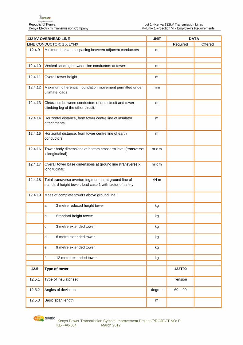
12.4.9 Minimum horizontal spacing between adjacent conductors
m
12.4.10 Vertical spacing between line conductors at tower: m
12.4.11 Overall tower height
m
12.4.12 Maximum differential, foundation movement permitted under
ultimate loads
mm
12.4.13 Clearance between conductors of one circuit and tower
climbing leg of the other circuit:
m
12.4.14 Horizontal distance, from tower centre line of insulator
attachments
m
12.4.15 Horizontal distance, from tower centre line of earth
conductors
m
12.4.16 Tower body dimensions at bottom crossarm level (transverse
x longitudinal)
m x m
12.4.17 Overall tower base dimensions at ground line (transverse x
longitudinal):
m x m
12.4.18 Total transverse overturning moment at ground line of
standard height tower, load case 1 with factor of safety
kN m
12.4.19 Mass of complete towers above ground line:
a. 3 metre reduced height tower
kg
b. Standard height tower:
kg
c. 3 metre extended tower
kg
d. 6 metre extended tower
kg
e. 9 metre extended tower
kg
f. 12 metre extended tower kg
12.5 Type of tower
132T90
12.5.1 Type of insulator set
Tension
12.5.2 Angles of deviation
degree 60 – 90
12.5.3 Basic span length
m
Republic of Kenya Lot 1 –Kenya 132kV Transmission Lines Kenya Electricity Transmission Company Volume 1 – Section VI - Employer’s Requirements
Kenya Power Transmission System Improvement Project /PROJECT NO: P- KE-FA0-004 March 2012
132 kV OVERHEAD LINE UNIT DATA
LINE CONDUCTOR: 1 X LYNX Required Offered
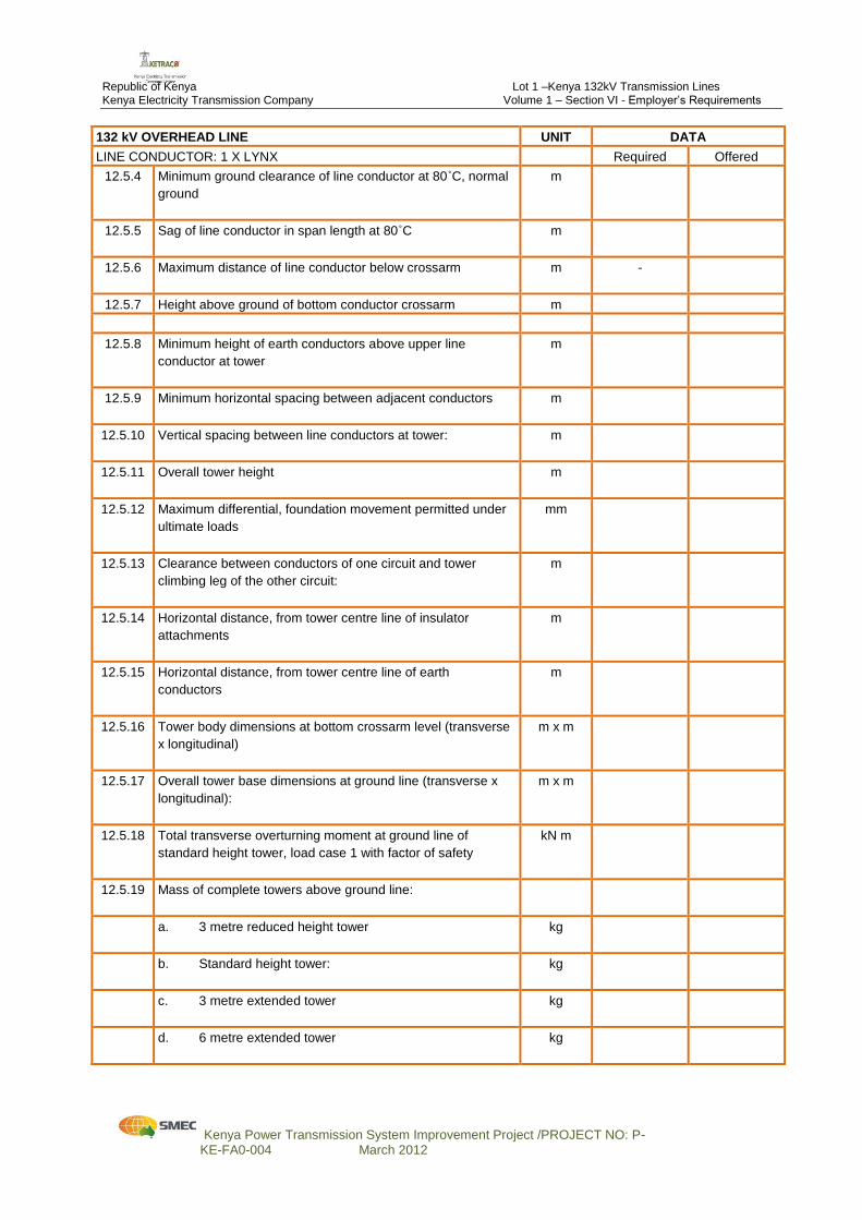
12.5.4 Minimum ground clearance of line conductor at 80˚C, normal
ground
m
12.5.5 Sag of line conductor in span length at 80˚C
m
12.5.6 Maximum distance of line conductor below crossarm
m -
12.5.7 Height above ground of bottom conductor crossarm m
12.5.8 Minimum height of earth conductors above upper line
conductor at tower
m
12.5.9 Minimum horizontal spacing between adjacent conductors
m
12.5.10 Vertical spacing between line conductors at tower:
m
12.5.11 Overall tower height
m
12.5.12 Maximum differential, foundation movement permitted under
ultimate loads
mm
12.5.13 Clearance between conductors of one circuit and tower
climbing leg of the other circuit:
m
12.5.14 Horizontal distance, from tower centre line of insulator
attachments
m
12.5.15 Horizontal distance, from tower centre line of earth
conductors
m
12.5.16 Tower body dimensions at bottom crossarm level (transverse
x longitudinal)
m x m
12.5.17 Overall tower base dimensions at ground line (transverse x
longitudinal):
m x m
12.5.18 Total transverse overturning moment at ground line of
standard height tower, load case 1 with factor of safety
kN m
12.5.19 Mass of complete towers above ground line:
a. 3 metre reduced height tower
kg
b. Standard height tower:
kg
c. 3 metre extended tower
kg
d. 6 metre extended tower
kg
Republic of Kenya Lot 1 –Kenya 132kV Transmission Lines Kenya Electricity Transmission Company Volume 1 – Section VI - Employer’s Requirements
Kenya Power Transmission System Improvement Project /PROJECT NO: P- KE-FA0-004 March 2012
132 kV OVERHEAD LINE UNIT DATA
LINE CONDUCTOR: 1 X LYNX Required Offered
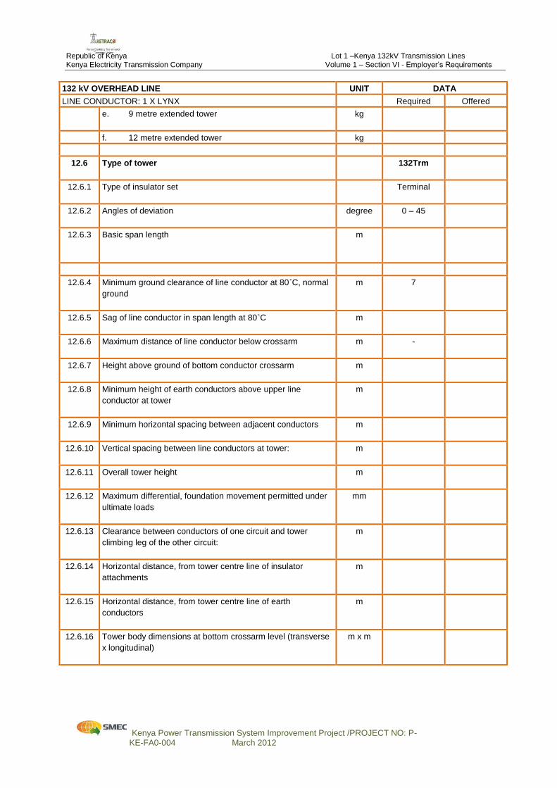
e. 9 metre extended tower
kg
f. 12 metre extended tower kg
12.6 Type of tower
132Trm
12.6.1 Type of insulator set
Terminal
12.6.2 Angles of deviation
degree 0 – 45
12.6.3 Basic span length
m
12.6.4 Minimum ground clearance of line conductor at 80˚C, normal
ground
m 7
12.6.5 Sag of line conductor in span length at 80˚C
m
12.6.6 Maximum distance of line conductor below crossarm
m -
12.6.7 Height above ground of bottom conductor crossarm
m
12.6.8 Minimum height of earth conductors above upper line
conductor at tower
m
12.6.9 Minimum horizontal spacing between adjacent conductors
m
12.6.10 Vertical spacing between line conductors at tower:
m
12.6.11 Overall tower height
m
12.6.12 Maximum differential, foundation movement permitted under
ultimate loads
mm
12.6.13 Clearance between conductors of one circuit and tower
climbing leg of the other circuit:
m
12.6.14 Horizontal distance, from tower centre line of insulator
attachments
m
12.6.15 Horizontal distance, from tower centre line of earth
conductors
m
12.6.16 Tower body dimensions at bottom crossarm level (transverse
x longitudinal)
m x m
Republic of Kenya Lot 1 –Kenya 132kV Transmission Lines Kenya Electricity Transmission Company Volume 1 – Section VI - Employer’s Requirements
Kenya Power Transmission System Improvement Project /PROJECT NO: P- KE-FA0-004 March 2012
132 kV OVERHEAD LINE UNIT DATA
LINE CONDUCTOR: 1 X LYNX Required Offered
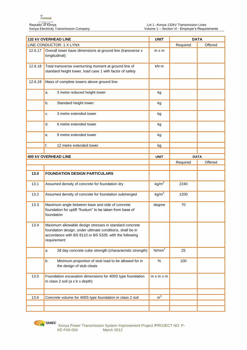
12.6.17 Overall tower base dimensions at ground line (transverse x
longitudinal):
m x m
12.6.18 Total transverse overturning moment at ground line of
standard height tower, load case 1 with factor of safety
kN m
12.6.19 Mass of complete towers above ground line:
a. 3 metre reduced height tower
kg
b. Standard height tower:
kg
c. 3 metre extended tower
kg
d. 6 metre extended tower
kg
e. 9 metre extended tower
kg
f. 12 metre extended tower kg
400 kV OVERHEAD LINE UNIT DATA
Required Offered
13.0 FOUNDATION DESIGN PARTICULARS
13.1 Assumed density of concrete for foundation dry
kg/m3 2240
13.2 Assumed density of concrete for foundation submerged
kg/m3 1200
13.3 Maximum angle between base and side of concrete
foundation for uplift “frustum” to be taken from base of
foundation
degree 70
13.4 Maximum allowable design stresses in standard concrete
foundation design, under ultimate conditions, shall be in
accordance with BS 8110 or BS 5328, with the following
requirement:
a. 28 day concrete cube strength (characteristic strength)
N/mm2 25
b. Minimum proportion of stub load to be allowed for in
the design of stub cleats
% 100
13.5 Foundation excavation dimensions for 400S type foundation
in class 2 soil (a x b x depth)
m x m x m
13.6 Concrete volume for 400S type foundation in class 2 soil m3
Republic of Kenya Lot 1 –Kenya 132kV Transmission Lines Kenya Electricity Transmission Company Volume 1 – Section VI - Employer’s Requirements
Kenya Power Transmission System Improvement Project /PROJECT NO: P- KE-FA0-004 March 2012
132 kV OVERHEAD LINE UNIT DATA
LINE CONDUCTOR: 1 X LYNX Required Offered
400 kV OVERHEAD LINE UNIT DATA
Required Offered
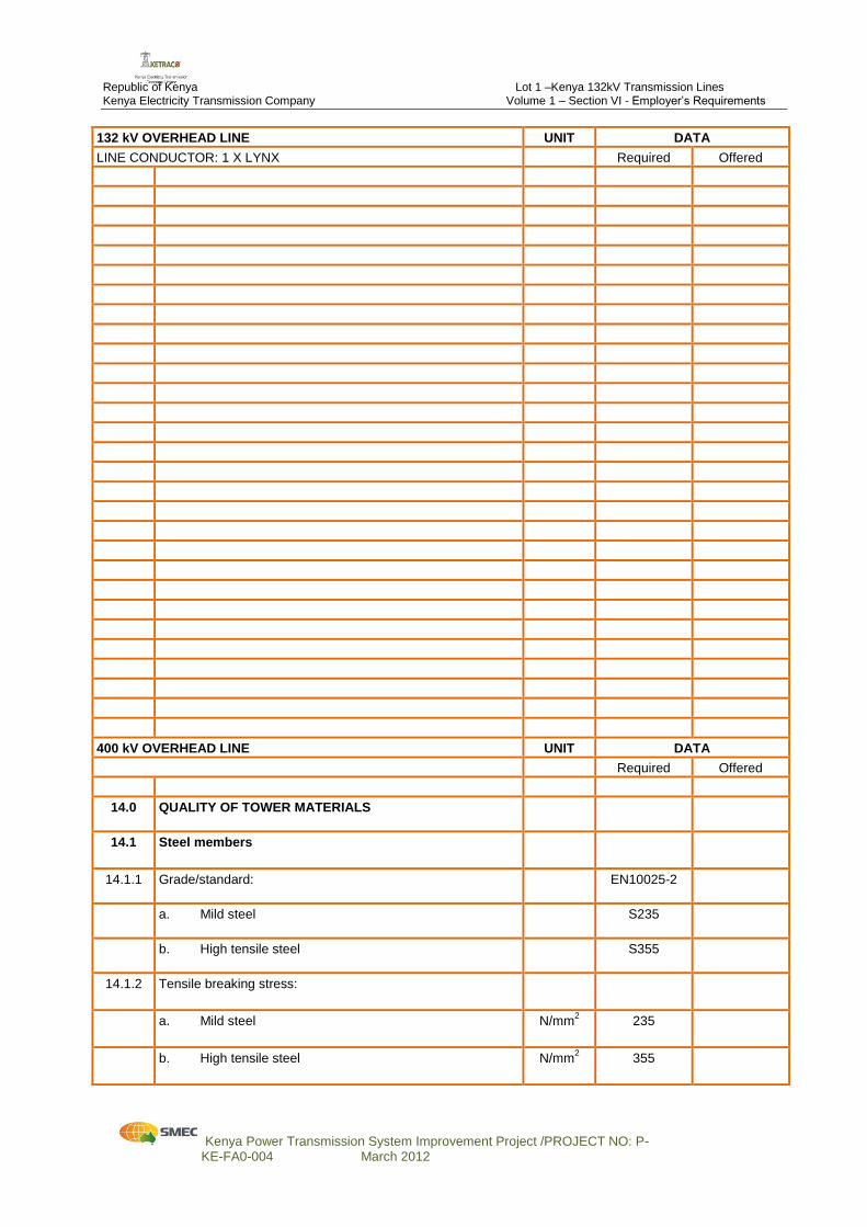
14.0 QUALITY OF TOWER MATERIALS
14.1 Steel members
14.1.1 Grade/standard:
EN10025-2
a. Mild steel
S235
b. High tensile steel
S355
14.1.2 Tensile breaking stress:
a. Mild steel
N/mm2 235
b. High tensile steel
N/mm2 355
Republic of Kenya Lot 1 –Kenya 132kV Transmission Lines Kenya Electricity Transmission Company Volume 1 – Section VI - Employer’s Requirements
Kenya Power Transmission System Improvement Project /PROJECT NO: P- KE-FA0-004 March 2012
132 kV OVERHEAD LINE UNIT DATA
LINE CONDUCTOR: 1 X LYNX Required Offered
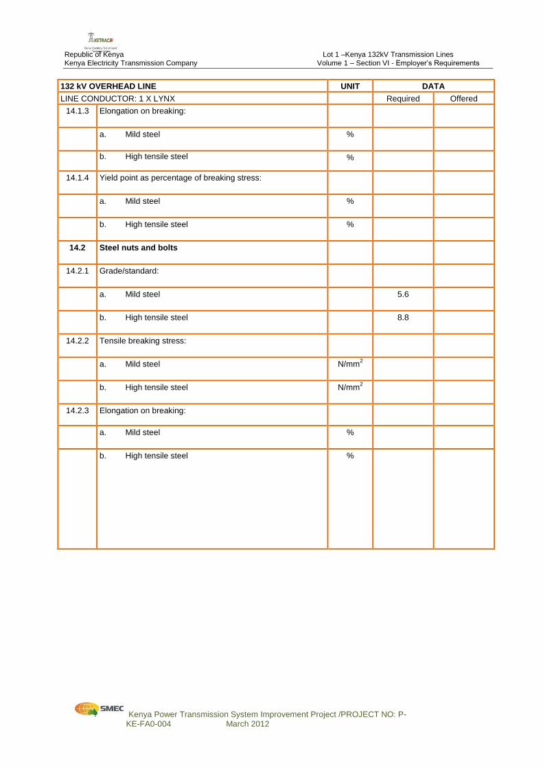
14.1.3 Elongation on breaking:
a. Mild steel
%
b. High tensile steel
%
14.1.4 Yield point as percentage of breaking stress:
a. Mild steel
%
b. High tensile steel
%
14.2 Steel nuts and bolts
14.2.1 Grade/standard:
a. Mild steel
5.6
b. High tensile steel
8.8
14.2.2 Tensile breaking stress:
a. Mild steel
N/mm2
b. High tensile steel
N/mm2
14.2.3 Elongation on breaking:
a. Mild steel
%
b. High tensile steel
%


![TOWARD EFFECTIVE STRUCTURAL IDENTIFICATION OF …eprints.usq.edu.au/34552/2/Nguyen_revised.pdfsuch as footbridges, long-span highway bridges, bridge towers and tall buildings [13-20]](https://img.pdfslide.us/doc/110x75/5fae5fa4cada98311313e5a1/toward-effective-structural-identification-of-such-as-footbridges-long-span-highway.jpg)