Embed Size (px)
Citation preview

Cisco OL-8834-04
C H A P T E R 7
4-Port Channelized OC-3/STM-1 Line Card ConfigurationThis chapter describes the procedures for configuring the Cisco 10000 series 4-Port Channelized OC-3/STM-1 line card, hereafter known as the 4-Port Channelized OC-3/STM-1 line card.
The 4-Port Channelized OC-3/STM-1 line card uses fractional T1 (n x DS0), DS-1, E1, fractional E1 (n x DS0) and DS3 IP services to connect ISP customers to the network backbone. It provides full duplex operation at OC-3 bandwidth rates using a (single-mode) fiber optic port that provides the Cisco 10000 series router with a single interface that connects up to 768 individual channelized options.
This chapter contains the following sections:
• Software Support, page 7-2
• SONET Channelization, page 7-2
• SDH Channelization, page 7-3
• Default Values, page 7-4
• Interface Syntax, page 7-8
• SONET-Framed Interface Configuration Sample, page 7-8
• SDH-Framed Interface Configuration Sample, page 7-10
• Configuring the SONET Controller for SONET or SDH Framing, page 7-14
• Creating a T3, VT, or AUG Controller, page 7-15
7-110000 Series Router Line Card Configuaration Guide

Chapter 7 4-Port Channelized OC-3/STM-1 Line Card Configuration Software Support
Software SupportTable 7-1 shows the minimum Cisco IOS release on each release train that supports the 4-Port Channelized OC-3/STM-1 line card.
Checking Hardware and Software CompatibilityThe PRE installed in the Cisco 10000 series router chassis must support the Cisco IOS software running on the router. Use the show version command to check the PRE version installed.
To see if a feature is supported by a Cisco IOS release, to locate the software document for that feature, or to check the minimum software requirements of Cisco IOS software with the hardware installed on your router, Cisco maintains the Software Advisor tool on Cisco.com at http://www.cisco.com/cgi-bin/Support/CompNav/Index.pl
This tool does not verify whether line cards within a system are compatible, but does provide the minimum Cisco IOS requirements for individual hardware line cards, modules, or options.
You must be a registered user on Cisco.com to access this tool.
SONET ChannelizationThe 4-Port Channelized OC-3/STM-1 line card supports the following SONET channelization modes:
• STS-1 > DS3/T3
• STS-1 > DS3/T3 > DS1
• STS-1 > DS3/T3 > DS3 subrate
• STS-1 > VT1.5 > DS1
• STS-1 > VT2 > E1
Table 7-2 shows serial interface examples for SONET channelizations on a previously-configured SONET-framed controller on the 4-Port Channelized OC-3/STM-1 line card.
Table 7-1 4-Port Channelized OC-3/STM-1 Line Card Software Support
Required PRE Minimum Cisco IOS Releases
PRE1 Cisco IOS Release 12.0(15)SL and later releases of Cisco IOS 12.0SLCisco IOS Release 12.0(17)ST and later releases of Cisco IOS 12.0STCisco IOS Release 12.0(22)S and later releases of Cisco IOS 12.0SCisco IOS Release 12.2(8)BZ and later releases of Cisco IOS 12.2BZ for SDH mode.For both SONET and SDH mode, use Cisco IOS Release 12.0(23)S and later releases of Cisco IOS 12.0S.
PRE2 Cisco IOS Release 12.3(7)XI and later releases of Cisco IOS 12.3XIFor both SONET and SDH mode, the use Cisco IOS Release 12.2(15)BX and later releases of Cisco IOS 12.2BX.Cisco IOS Release 12.2(28)SB and later releases of Cisco IOS 12.2SB
7-2Cisco 10000 Series Router Line Card Configuaration Guide
OL-8834-04

Chapter 7 4-Port Channelized OC-3/STM-1 Line Card Configuration SDH Channelization
SDH ChannelizationThe 4-Port Channelized OC-3/STM-1 line card supports the following SDH channelization modes:
• STM-1 > AU-3 > DS3/T3
• STM-1 > AU-3 > DS3/T3 > DS3 subrate
• STM-1 > AU-3 > TUG-2 > C-11 > DS1/T1
• STM-1 > AU-3 > TUG-2 > C-12 > E1
• STM-1 > AU-4 > TUG-3 > TUG-2 > C-11 > DS1/T1
• STM-1 > AU-4 > TUG-3 > TUG-2 > C-12 > E1
Table 7-3 shows serial interface examples for SDH channelizations on a previously-configured SDH-framed controller on the 4-Port Channelized OC-3/STM-1 line card.
Table 7-2 SONET Interface Examples for a SONET-Framed Controller
Interface Type Syntax
STS-1,over DS3/T3
Router(config)# interface serial<slot>/<subslot>/<port>.<T3#>
STS-1,over DS3/T3,channelized to DS1
Router(config)# interface serial <slot>/<subslot>/<port>.<T3#>:[chan]
STS-1,over subrated DS3/T3
Router(config)# interface serial<slot>/<subslot>/<port>.<T3#>
STS-1,over VT1.5,channelized to DS1
Router(config)# interface serial <slot>/<subslot>/<port>.<VT#>:[chan]
STS-1,over VT2, channelized to E1
Router(config)# interface serial<slot>/<subslot>/<port>.<VT#>:[chan]
Table 7-3 SDH Interface Examples for an SDH-Framed Controller
Interface Type Syntax
STM-4,over STM-1over AU-3,over DS3/T3
Router(config)# interface serial<slot>/<subslot>/<port>.<AU-3#>/<T3#>
STM-4,over STM-1over AU-3,over a subrated DS3/T3
Router(config)# interface serial<slot>/<subslot>/<port>.<AU-3#>/<T3#>
7-3Cisco 10000 Series Router Line Card Configuaration Guide
OL-8834-04

Chapter 7 4-Port Channelized OC-3/STM-1 Line Card Configuration Default Values
Default ValuesThe 4-Port Channelized OC-3/STM-1 line card has two sets of command default values. The set of default values in use is determined by the framing command—either SONET framing or SDH framing.
The following tables contains command default values, and indicate which configuration mode you need to be in to enter a command. Where applicable, the tables also indicate which commands apply to which line types. The tables include the commands used for modifying a default value and indicates whether a value needs to be the same (or opposite) on the remote end of the connection.
Default Values for SONET FramingThis section contains tables of command default values that apply when the 4-Port Channelized OC-3/STM-1 line card is configured for SONET framing.
Table 7-4 lists the default values for commands that are available in SONET controller configuration mode when the 4-Port Channelized OC-3/STM-1 line card is configured for SONET framing.
Table 7-5 lists the default values for commands that are available in T3 controller configuration mode when the 4-Port Channelized OC-3/STM-1 line card is configured for SONET framing.
Table 7-6 lists the default values for commands that are available in T1 controller configuration mode, under a T3 controller, when the 4-port STM-4 line card is configured for SONET framing.
STM-4,over STM-1over AU-3,over TUG-2,over C-11 (DS1/T1)
Router(config)# interface serial <slot>/<subslot>/<port>.<AU-3#>/<TUG-2>/<C-11>:[chan]
STM-4,over STM-1over AU-3,over TUG-2,over C-12 (E1)
Router(config)# interface serial <slot>/<subslot>/<port>.<AU-3#>/<TUG-2>/<C-12>:[chan]
STM-4,over STM-1over AU-4,over TUG-3,over TUG-2,over C-11 (DS1/T1)
Router(config)# interface serial<slot>/<subslot>/<port>.<AU-4#>/<TUG-3>/<TUG-2>/<C-11>:[chan]
STM-4,over STM-1over AU-4,over TUG-3,over TUG-2,over C-12 (E1)
Router(config)# interface serial<slot>/<subslot>/<port>.<AU-4#>/<TUG-3>/<TUG-2>/<C-12>:[chan]
Table 7-3 SDH Interface Examples for an SDH-Framed Controller (continued)
Interface Type Syntax
7-4Cisco 10000 Series Router Line Card Configuaration Guide
OL-8834-04

Chapter 7 4-Port Channelized OC-3/STM-1 Line Card Configuration Default Values
Table 7-7 lists the default values for commands that are available in VT controller configuration mode when the 4-Port Channelized OC-3/STM-1 line card is configured for SONET framing.
Table 7-4 Default Values for SONET Controller Configuration Commands under SONET
Framing
Command NameDefault Setting Command Syntax Remote Side Setting
SONET Controller Configuration Mode
clock source1
1. The default value for SONET clock source is line. At least one side of the connection must be set to internal.
line clock source {internal | line} One side set to internal
framing sdh framing {sonet | sdh} Same
loopback no loopback [no] loopback {internal | line} —
overhead 1 for J00 for S1S0
overhead {j0 | s1s0} —
Table 7-5 Default Values for T3 Controller Configuration Commands under SONET Framing
Command NameDefault Setting Command Syntax Remote Side Setting
T3 Controller Configuration Mode
cablelength 0 cablelength length —
channelized channelized [no] channelized —
clock source internal clock source {line | internal} One side set to internal
framing auto-detect framing {auto-detect | c-bit | m23} Same
idle pattern 0X7e (flags) idle pattern {0x0 to 0xFF} Same
overhead 4 for c264 for j1
overhead {c2 | j1} —
Table 7-6 Default Values for VT Controller Configuration Commands under SONET Framing
Command NameDefault Setting Command Syntax
Remote Side Setting
VT Controller Configuration Mode
overhead 2 for c264 for j1
overhead {c2 | j1} —
7-5Cisco 10000 Series Router Line Card Configuaration Guide
OL-8834-04

Chapter 7 4-Port Channelized OC-3/STM-1 Line Card Configuration Default Values
Default Values for SDH FramingThis section contains tables of command default values that apply when the 4-Port Channelized OC-3/STM-1 line card is configured for SDH framing.
Table 7-8 lists the default values for commands that are available in SONET controller configuration mode when the 4-Port Channelized OC-3/STM-1 line card is configured for SDH framing.
Table 7-9 lists the default values for commands that are available in AU-3 controller configuration mode for both AU-3 and AU-4-TUG-3 when the 4-Port Channelized OC-3/STM-1 line card is configured for SDH framing.
Table 7-10 lists the default values for T3 commands when the 4-Port Channelized OC-3/STM-1 line card is configured for SDH framing.
Table 7-11 lists default values for T1 and E1 commands when the 4-Port Channelized OC-3/STM-1 line card is configured for either SONET or SDH framing.
Table 7-7 Default Values for T1 and E1 Configuration Commands under SONET Framing
Command NameDefault Setting Command Syntax Remote Side Setting
t1 clock source internal t1 ch_group_number clock source{line | internal}
One side set to internal
t1 framing esf t1 t1-number framing {esf | sf} Same
e1 clock source internal e1 ch_group_number clock source{line |internal}
One side set to internal
e1 framing crc4 e1 e1-number framing [crc4 | no-crc4] Same
Table 7-8 Default Values for SONET Controller Configuration Commands under SDH Framing
Command Name Default Setting Command Syntax Remote Side Setting
SONET Controller Configuration Mode under SDH
clock source1
1. The default value for SDH clock source is line. At least one side of the connection must be set to internal.
line [no] clock source {internal|line}
One side set to internal
framing sdh framing {sonet | sdh} Same
loopback no loopback [no] loopback {internal | line} —
overhead 1 for j02 for S1S0
overhead {j0 | s1s0} —
aug controller no aug controller [no] aug controller <au-3|au-4-tug-3>
—
7-6Cisco 10000 Series Router Line Card Configuaration Guide
OL-8834-04
Chapter 7 4-Port Channelized OC-3/STM-1 Line Card Configuration Default Values
Table 7-9 Default Values for AU-3/AU-4-TUG-3 Controller Configuration Commands for AU-3
and AU-4-TUG-3 under SDH Framing
Command Name Default Setting Command Syntax Remote Side Setting
AU-3/AU-4-TUG-3 Controller Configuration Mode under SDH
clock source internal clock source {line | internal} One side set to internal
overhead 0 for c216 for j1
overhead {c2 | j1} —
Table 7-10 Default Values for T3 Configuration Commands under SDH Framing
Command Name Default Setting Command SyntaxRemote Side Setting
crc 16 crc {16 | 32} —
encapsulation HDLC encapsulation {frame-relay | hdlc | ppp} Same
idle-character flags (0x7e) idle-character {flags | marks} —
keepalive 10 seconds keepalive period —
Table 7-11 Default Values for T1 and E1 Interface Configuration Commands
Command NameDefault Setting Command Syntax Remote Side Setting
T1 Interface Configuration Mode
crc 16 [no] crc [16 | 32] Same
DSU bandwidth 44210 dsu bandwidth bandwidth Same
DSU mode cisco dsu mode mode Same
encapsulation HDLC encapsulation [hdlc | ppp] Same
framing c-bit framing [c-bit | m13] Same
idle character flags (0x7e) idle character [flags | marks] Same
keepalive 10 seconds keepalive seconds Same
mtu 4470 mtu size Same
E1 Interface Configuration Mode
crc 16 [no] crc [16 | 32] Same
encapsulation HDLC encapsulation [hdlc | ppp] Same
framing c-bit framing [c-bit | m13] Same
idle character flags (0x7e) idle character [flags | marks] Same
keepalive 10 seconds keepalive Same
mtu 4470 mtu size Same
7-7Cisco 10000 Series Router Line Card Configuaration Guide
OL-8834-04

Chapter 7 4-Port Channelized OC-3/STM-1 Line Card Configuration Interface Syntax
Interface SyntaxTo specify an unchannelized or channelized interface on the 4-port STM-1 line card in a configuration command, use the syntax shown in Table 7-12.
Examples:
• Modifying T1 interface 6 in controller configuration mode:
Router(config)# controller t3 2/0/0.1Router(config-controller)# t1 6 command
• Modifying T1 interface 6, channel group number 8 in interface configuration mode:
Router(config)# interface serial 2/0/0.1/6:8Router(config-if)
SONET-Framed Interface Configuration SampleYou can configure up to 12 STS-1 connections on a 4-Port Channelized OC-3/STM-1 line card. Each STS-1 connection can be configured as a T3 controller or as a VT controller.
The following procedure walks you through the basic steps for creating full-rate and subrate T3 interfaces, as well as T1 and fractional T1 interfaces. Each T3 controller can be configured as a single T3 interface (full or subrate), as 28 T1 interfaces, or as an even larger number of fractional T1s.
Step 1 Set the framing type to SONET using the framing command.
Router(config)# controller sonet 2/0/0Router(config-controller)# framing sonet
Step 2 Assign an STS-1 path to a T3 interface. In this example, the path command is used to set up four T3 interfaces:
Router(config-controller)# path 1 controller t3Router(config-controller)# path 2 controller t3Router(config-controller)# path 3 controller t3Router(config-controller)# exit
Step 3 Create an interface. In the following examples, each type of interface is created in a different T3 controller (4/0/0.1 through 4/0/0.4).
Full-Rate T3 Interface
a. Enter controller configuration mode.
Router(config)# controller t3 2/0/0.1Router(config-controller)#
Table 7-12 Interface Syntax for the 4-Port Channelized OC-3/STM-1 Line Card
Type of Interface Slot Sub-slot Port STS-1 Path (T3)T1 or E1 Number
Channel Group Number
Unchannelized 1 to 8/ 0/ 0 to 3. 1 to 12 — —
Channelized 1 to 8/ 0/ 0 to 3. 1 to 12/ 1 to 28: for T11 to 32: for E1
0 to 23 for T10 to 31 for E1
7-8Cisco 10000 Series Router Line Card Configuaration Guide
OL-8834-04

Chapter 7 4-Port Channelized OC-3/STM-1 Line Card Configuration SONET-Framed Interface Configuration Sample
b. To create a full-rate T3 interface, you must eliminate the T1 interfaces by entering the no channelized command.
Router(config-controller)# no channelizedRouter(config-controller)# exitRouter(config)#
c. Enter interface configuration mode.
Router(config)# interface serial 2/0/0.1
d. Go to Step 4.
Subrate T3 Interface
a. Enter controller configuration mode.
Router(config)# controller t3 2/0/0.2Router(config-controller)#
b. To create a subrate T3 interface, first create a full-rate one.
Router(config-controller)# no channelizedRouter(config-controller)# exitRouter(config)#
c. Enter interface configuration mode, where you can use the dsu bandwidth command to create a subrate T3 interface. In this example, a subrate T3 interface is created that has a bandwidth of 16000 kbps.
Router(config)# interface serial 2/0/0.2Router(config-if)# dsu bandwidth 16000
d. Go to Step 4.
Channelized T3 with a Full T1 Interface
a. Enter controller configuration mode.
Router(config)# controller t3 2/0/0.3Router(config-controller)#
b. Use the t1 channel group command to create a T1 interface. In the following example, T1 interface 1 (of 28) is defined as being made up of a single channel group, number 20 (any number between 0 and 23). This channel group consists of all 24 DS0 timeslots.
Router(config-controller)# t1 1 channel-group 20 timeslots 1-24
c. Go to interface configuration mode for the channel group you just created.
Router(config)# interface serial 2/0/0.3/1:20
d. Go to Step 4.
Channelized T3 with a Fractional T1 Interface
a. Enter controller configuration mode.
Router(config)# controller t3 2/0/0.4Router(config-controller)#
7-9Cisco 10000 Series Router Line Card Configuaration Guide
OL-8834-04

Chapter 7 4-Port Channelized OC-3/STM-1 Line Card Configuration SDH-Framed Interface Configuration Sample
b. Use the t1 channel group command to create fractional T1 interfaces. In the following example, T1 interface 3 (of 28) is defined as being made up of three channel groups, numbers 19, 20, and 21 (any numbers between 0 and 23). The channel groups consist of a total of 24 DS0 timeslots. Each channel group represents a separate interface.
Router(config-controller) t1 3 channel-group 19 timeslots 1-6, 10Router(config-controller) t1 3 channel-group 20 timeslots 7,8,9Router(config-controller) t1 3 channel-group 21 timeslots 11-24
c. Go to interface configuration mode for one of the channel groups. For example:
Router(config)# interface serial 2/0/0.4/3:19
d. Go to Step 4.
Step 4 Enter the encapsulation method. This example shows the command for using Frame Relay encapsulation. You can also choose PPP or HDLC.
Router(config-if)# encapsulation frame-relay
Step 5 If IP routing is enabled on the system, you can assign an IP address and subnet mask. For example:
Router(config-if)# ip address 172.16.32.49 255.255.0.0
Step 6 Add any configuration subcommands required to enable routing protocols and set the interface line characteristics.
Step 7 Change the shutdown state to up, which enables the interface.
Router(config-if)# no shutdown
Step 8 When you have entered all of the configuration subcommands to complete the configuration, press Ctrl-Z to exit configuration mode.
Step 9 Write the new configuration to NVRAM.
Router# copy running-config startup-config
After you create an interface configuration, you can modify it at any time by using the appropriate Cisco IOS configuration commands.
SDH-Framed Interface Configuration SampleIf you configure the 4-port STM-1 line card for SDH framing, each OC-3/STM-1 port can be configured as:
• Three AU-3 controllers, each of which can be configured as a T3 interface or as 28 T1 interfaces or 21 E1 interfaces. These interfaces can be channelized into fractional T1s or E1s.
• Three AU-4-TUG-3 controllers, each of which can be configured as 28 T1 interfaces or up to 21 E1 interfaces. These interfaces can be channelized into fractional T1s or E1s.
Note AU-3 and AU-4-TUG-3s are based on the higher order path, and do not operate independently, but operate in groups of three. If you shutdown any AU-3 or AU-4-TUG-3 controller, the other two controllers on the same SONET port are also shut down.
7-10Cisco 10000 Series Router Line Card Configuaration Guide
OL-8834-04

Chapter 7 4-Port Channelized OC-3/STM-1 Line Card Configuration SDH-Framed Interface Configuration Sample
The SONET controller command specifies the mode, and creates three [sub]controllers of that type, which you can configure like any other controller.
The format created adds a subport extension to the controller SONET name. The form of the subport extension is different for AU-3 and AU-4-TUG-3 controllers as the following examples show:
AU-3 Controller Syntaxcontroller au-3 <slot>/<subslot>/<port>.<AU-3#>
For example, the controller command for AU-3 #3 on port 0 of a 4-Port Channelized OC-3/STM-1 line card in slot 2 is:
controller au-3 2/0/0.3
AU-4-TUG-3 Controller Syntaxcontroller au-4-tug-3 <slot>/<subslot>/<port>.<AU-4#>/<TUG-3#>
For example, the command for a controller created for TUG-3 #3 on AU-4 of port 0 of a 4-Port Channelized OC-3/STM-1 line card in slot 2 is:
controller au-4-tug-3 2/0/0.1/3
Show Controller Command SyntaxTo display the settings for specific on AU-3 and AU-4-TUG-3 controllers, use the show controller command.
For AU-3:
show controller au-3 <slot>/<subslot>/<port>.<AU-3#>[/<tug-2>/<t1>]
For AU-4-TUG-3:
show controller au-4-tug-3<slot>/<subslot>/<port>.<AU-4#>/<TUG-3#>[/<tug-2>/<t1 or e1>]
Where:
• slot is 1 to 8
• subslot is 0
• port is always 0
• AU-3# is 1 to 12
• AU-4# is always 1
• TUG-3# is 1 to 12
• tug-2 is 1 to 7
• t1 is 1 to 4 or e1 is 1 to 3
Note The [/<tug-2>/<t1>] options are only available if a mode (C-11 or C-12) is configured on the controller.
For example, for T1 over AU-3, the command to display the settings for AU-3 #3 for a line card in slot 2 is:
show controller au-3 2/0/0.3
7-11Cisco 10000 Series Router Line Card Configuaration Guide
OL-8834-04

Chapter 7 4-Port Channelized OC-3/STM-1 Line Card Configuration SDH-Framed Interface Configuration Sample
For AU-4-TUG-3, the command to display the settings for TUG-3 #3 on AU-4 of a 4-Port Channelized OC-3/STM-1 line card in slot 2 is:
show controller au-4-tug-3 2/0/0.1/3
To display a specific TUG-2 and E1 on the same AU-4-TUG-3, use the command:
show controller au-4-tug-3 2/0/0-1/3/1/3
AU-3 Controller InterfacesUse the following procedure to create T3 and T1 interfaces using AU-3 controllers.
Step 1 Enter SONET controller configuration mode from global configuration mode.
In this example, the 4-port STM-1 line card is in slot 1.
Router(config)# controller sonet 2/0/0Router(config-controller)#
Step 2 Use the aug controller command to specify the mode of operation for an OC-3/STM-1 port (for an AU-3, twelve controllers are created: 2/0/0.1 to 2/0/0.12).
Router(config-controller)# aug controller au-3Router(config-controller)#
Full-Rate T3 Interface
Note T3 lines can only operate over AU-3 controllers.
a. Configure the controller on the port.
This example shows AU-3 controller #3 configured for a line card in slot 2.
Router(config-controller)# controller au-3 2/0/0.3Router(config-controller)#
b. Set the container mode to C-3 to establish a T3 interface.
Router(config-controller)# mode c-3Router(config-controller)# exitRouter(config)#
C-3 mode creates a serial interface at the unchannelized T3 level.
T1 Channel Group Interface
a. Configure the controller on the STM-1 port.
This example shows AU-3 controller #2 configured on the STM-1 port for a line card in slot 2.
Router(config)# controller au-3 2/0/0.2Router(config-controller)#
b. Set the container mode to C-11 to establish a T1 interface.
Router(config-controller)# mode c-11Router(config-controller)#
c. Create a T1 interface.
7-12Cisco 10000 Series Router Line Card Configuaration Guide
OL-8834-04

Chapter 7 4-Port Channelized OC-3/STM-1 Line Card Configuration SDH-Framed Interface Configuration Sample
In the following example, the TUG-2 interface is defined as 1 (any number between 1 and 7), the T1 interface is 2 (any number between 1 and 4), and is made up of a single channel group, 5 (any number between 0 and 23). This channel group consists of all 24 DS0 timeslots.
Router(config-controller)# tug-2 1 t1 2 channel-group 5 timeslots 1-24Router(config-controller)#
AU-4-TUG-3 Controller InterfacesUse the following procedure to create T1 and E1 interfaces using AU-4-TUG-3 controllers.
Caution The three AU-4-TUG-3 controllers created on a port are based on the same higher order path and do not operate independently from one another. In other words, when you “shutdown” any AU-4-TUG-3 controller, the other two controllers on the same SONET port are also shut down.
Step 1 Enter SONET controller-configuration mode.
In this example, the line card is in slot 2.
Router(config)# controller sonet 2/0/0Router(config-controller)#
Step 2 Use the aug controller command to specify the mode of operation for the STM-1 port (for an AU-4, three controllers are created).
Router(config-controller)# aug controller au-4-tug-3Router(config-controller)#
T1 Channel Group Interface over AU-4-TUG-3/TUG-2
a. Configure the controller on an STM-4 port. This example shows AU-4-TUG-3 controller #2 configured on port 0for a line card in slot 2.
Router(config-controller)# controller au-4-tug-3 2/0/0.1/2Router(config-controller)#
b. Set the container mode to C-11 to establish a T1 interface.
Router(config-controller)# mode c-11Router(config-controller)#
c. Create a T1 interface.
In the following example, the TUG-2 interface is 1 (any number between 1 and 7), the T1 interface is 2 (any number between 1 and 4,) and is defined as a single channel group, 5 (any number between 0 and 23). This channel group consists of all 24 DS0 timeslots.
Router(config-controller)# tug-2 1 t1 2 channel-group 5 timeslots 1-24Router(config-controller)#
E1 Channel Group Interface over AU-4-TUG-3/TUG-2
a. Configure the controller on an STM-4 port.
This example shows AU-4-TUG-3 controller #2 configured on port 0 of a line card in slot 2.
Router(config-controller)# controller au-4-tug-3 2/0/0.1/2Router(config-controller)#
7-13Cisco 10000 Series Router Line Card Configuaration Guide
OL-8834-04

Chapter 7 4-Port Channelized OC-3/STM-1 Line Card Configuration Configuring the SONET Controller for SONET or SDH Framing
b. Set the container mode to C-12 to establish an E1 interface.
Router(config-controller)# mode c-12Router(config-controller)#
c. Create an E1 interface.
In the following example, the TUG-2 interface is 1 (any number between 1 and 7), the E1 interface is 2 (any number between 1 and 3), and is defined as a single channel group, 5 (any number between 0 and 31). This channel group consists of all 31 DS0 time slots.
Router(config-controller)# tug-2 1 e1 2 channel-group 5 timeslots 1-31Router(config-controller)#
Configuring the SONET Controller for SONET or SDH FramingBy default, the 4-port STM-1 line card consists of 12 STS-1 connections. To set up the 4-port STM-1 line card, you must configure each STS-1 as a T3 or VT interface. This section describes the commands used to create T3 and VT interfaces and test STS-1 connections. This section describes the following:
• Entering Controller-Configuration Mode, page 7-14
• Selecting SONET or SDH Framing, page 7-14
• Configuring the SONET Controller Loopback Mode, page 7-15
Entering Controller-Configuration ModeUse the controller sonet command to enter controller-configuration mode, where you can configure the controller:
controller sonet slot/subslot/port
Where slot is 1 to 8, and subslot and port are both 0.
The following example shows you how to enter SONET controller configuration mode for a card in slot 2:
Router(config)# controller sonet 2/0/0ROuter(config-controller)#
Selecting SONET or SDH FramingTo configure the 4-port STM-1 line card for SONET, you must first set the framing type to either SONET or SDH using the framing command.
If the 4-port STM-1 line card framing was previously configured for either SONET or SDH, and you wish to change the framing, you must enter the no framing command to return the line card to the default values. Then use the framing <framing type> command to set the new framing.
Caution If you enter the no framing command, the line card configuration is erased, and all default line card values are restored. Use the command with caution.
framing {sonet | sdh}[no] framing
7-14Cisco 10000 Series Router Line Card Configuaration Guide
OL-8834-04

Chapter 7 4-Port Channelized OC-3/STM-1 Line Card Configuration Creating a T3, VT, or AUG Controller
The default is SONET.
Use the no form of the command to remove framing and return the line card to the default values.
The following example shows you how to specify SONET framing for the 4-port STM-1 line card in slot 2:
Router(config)# controller sonet 2/0/0Router(config-controller)# framing sonet
Configuring the SONET Controller Loopback ModeYou can enable SONET controller loopbacks by using the loopback command.
loopback [internal | line][no] loopback [internal | line]
The default is no loopback.
Use the no form of the command to stop a loopback.
For more information on the loopback command, refer to the online Cisco 10000 Series ESR Troubleshooting Guide.
The commands in this example run an internal loopback on the 4-Port Channelized OC-3/STM-1 line card in slot 2:
Router(config)# controller sonet 2/0/0Router(config-controller)# loopback internal
Creating a T3, VT, or AUG ControllerThis section shows you how to create and configure T3, VT, or AUG controllers, and contains the following sections:
• Designating an STS-1 Path as a T3 or VT under SONET Framing, page 7-15
• Designating an STM-4 Port as an AU-3 or AU-4-TUG-3 Controller under SDH Framing, page 7-16
• Configuring the SONET Controller Loopback Mode, page 7-15
• VT Commands under SONET Framing, page 7-17
• Unchannelized T3 Commands under SONET or SDH Framing, page 7-17
• Channelized T3 Commands under SONET or SDH Framing, page 7-21
• Creating T1 or E1 Channel Groups under SONET or SDH Framing, page 7-26
• Channelized T1 Commands under SONET or SDH Framing, page 7-29
Designating an STS-1 Path as a T3 or VT under SONET FramingWhen the 4-port STM-1 line card is configured for SONET framing, you can use the path command to designate an STS-1 path as a T3 or VT controller. You can designate up to 12 STS-1 channels. (Figure 7-1 on page 7-22 shows the relationship between the STM-1, T3 interfaces, VT interfaces, and T1 interfaces.
path STS_number controller {t3 | vt}
7-15Cisco 10000 Series Router Line Card Configuaration Guide
OL-8834-04

Chapter 7 4-Port Channelized OC-3/STM-1 Line Card Configuration Creating a T3, VT, or AUG Controller
Where STS_number is the virtual T3 or VT controller. Enter a value from 1 to 12.
Use the no form of the command to remove a T3 or VT controller.
In the following example, STS-1 number 1 is defined as a T3 line and controller T3 number 2/0/0.1 is generated:
Router(config)# controller sonet 2/0/0Router(config-controller)# path 1 controller t3
In the next example, STS-1 number 1 is defined as a VT line and a VT controller 2/0/0.1 is generated:
Router(config)# controller sonet 2/0/0Router(config-controller)# path 1 controller vt
Designating an STM-4 Port as an AU-3 or AU-4-TUG-3 Controller under SDH Framing
When the 4-port STM-1 line card is configured for SDH framing, you can use the aug controller command to specify the mode of operation for an STM-4 port as an AU-3 controller or an AU-4-TUG-3 controller. This command creates 12 subcontrollers of the designated type, which you can then configure like any other controller.
[no] aug controller <au-3|au-4-tug-3>
Where au-3 and au-4-tug-3 designate the type of controller. Enter a value from 1 to 12.
Use the no form of the command to remove an AU-3 or AU-4-TUG-3 controller.
The format of the name for these controllers requires you to add a subport extension to the SONET controller name. The subport extension is different for AU-3 and AU-4-TUG-3 controllers.
AU-3 Controller
For an AU-3 controller, the syntax is:
controller au-3 <slot>/<subslot>/<port>.<AU-3#>
For example, the following command Uses AU-3 controller #3 on port 0 of a line card in slot 2.
Router(config-controller)# controller au-3 2/0/0.3
AU-4-TUG-3 Controller
For an AU-4-TUG-3 controller, the syntax is:
Router(config-controller)# controller au-4-tug-3 <slot>/<subslot>/<port>.<AU-4#>/<TUG-3#>
Note The twelve AU-4-TUG-3 controllers created on an SDH-framed SONET port are based on the same higher order path and do not operate independently from one another. In other words, when you “shutdown” any AU-4-TUG-3 controller, the other two controllers on the same SDH-framed SONET port are also shut down.
For example, the following command uses TUG-3 #3 on AU-4 of port 0 of an 4-port STM-1 line card in slot 2.
Router(config-controller)# controller au-4-tug-3 2/0/0.1/3
7-16Cisco 10000 Series Router Line Card Configuaration Guide
OL-8834-04

Chapter 7 4-Port Channelized OC-3/STM-1 Line Card Configuration Creating a T3, VT, or AUG Controller
VT Commands under SONET FramingThis section describes how to use the controller vt command to further channelize the SONET-framed STS-1 controller of the 4-port STM-1 line card.
Entering Controller Configuration Mode for VT
A virtual tributary (VT) controller on a 4-port STM-1 line card can be channelized into 28 T1 (VT1.5) interfaces or 21 E1 (VT2) interfaces. You can use the controller vt command to shut down a VT link or to change the settings for a T1 or E1 interface.
For information about T1 configuration settings, see “Creating T1 or E1 Channel Groups under SONET or SDH Framing” section on page 7-26, and the “Channelized T1 Commands under SONET or SDH Framing” section on page 7-29.
You can configure a VT link by entering the controller vt command.
slot/sub-slot/port.path
Where path is a value from 1 to 12. Each number represents a VT that houses 28 T1 lines or 21 E1 lines.
For example:
Router# configure terminalEnter configuration commands, one per line. End with CNTL/Z.Router(config)# controller vt 1/0/0.1Router(config-controller)#
Unchannelized T3 Commands under SONET or SDH FramingThis section shows you how to configure an unchannelized T3 on a SONET-framed or SDH-framed controller.
If the 4-port STM-1 line card is configured for SONET framing, a T3 interface is channelized into 28 T1 interfaces by default. You must unchannelize the T3 interface to create a full-rate or subrate T3 interface.
If the 4-Port Channelized OC-3/STM-1 line card is configured for SDH framing, C-3 container mode automatically creates an unchannelized T3 serial interface.
This section describes the commands you use to create, customize, and test full-rate and subrate T3 interfaces. This section describes the following:
• Entering Controller Configuration Mode for T3, page 7-18
• Configuring a T3 Interface on a SONET-Framed Controller as Unchannelized, page 7-18
• Implementing Subrate T3, page 7-18
• Setting a Framing Type, page 7-19
• Specifying a DSU Mode, page 7-19
• Enabling Scrambling, page 7-19
• Specifying the Idle Character, page 7-19
• Running a T3 BER Test under SONET or SDH Framing, page 7-20
You can also use the following commands, described in the “Channelized T3 Commands under SONET or SDH Framing” section on page 7-21, when you configure unchannelized T3: clock source, mdl, equipment, and loopback.
7-17Cisco 10000 Series Router Line Card Configuaration Guide
OL-8834-04

Chapter 7 4-Port Channelized OC-3/STM-1 Line Card Configuration Creating a T3, VT, or AUG Controller
Entering Controller Configuration Mode for T3
To create an unchannelized T3 interface, you must first enter controller configuration mode for the T3 controller you want to configure.
controller T3 slot/sub-slot/port.path
Where path specifies the T3 interface number.
The following example shows how to enter controller configuration mode:
Router(config)# controller T3 1/0/0.1Router(config-controller)#
Configuring a T3 Interface on a SONET-Framed Controller as Unchannelized
If the 4-Port Channelized OC-3/STM-1 line card is configured for SONET framing, you must unchannelize the T3 interface to create a full-rate or subrate T3 interface.
You can configure the T3 interface as unchannelized (clear channel) by entering the no channelized command.
[no] channelized
Caution The no channelized command removes all channel groups from a channelized T3 interface. If you have already configured channel groups, use this command with caution.
Use the channelized command to return the interface to its default. The default value for a T3 interface is channelized.
In the following example, an unchannelized T3 interface is created:
Router(config)# controller T3 1/0/0.1Router(config-controller)# no channelized
Implementing Subrate T3
You can implement subrate T3 by specifying the bandwidth for an unchannelized T3 interface. To do so, use the dsu bandwidth bandwidth command from interface configuration mode.
dsu bandwidth bandwidth[no] bandwidth bandwidth
Where bandwidth is a numeric value between 0 and 44,210 kbps.
The default bandwidth is 44,210 kbps.
To return to the default bandwidth, use the no form of this command.
When you specify a value, the software sets the bandwidth to the closest acceptable bandwidth based on the timeslot size for the current DSU mode.
For you to properly use this command, the remote side of the connection must have a Cisco 7200 router or Cisco 7500 router with a PA-T3 or PA-2T3 port adapter or a T3 DSU supported by the dsu mode command.
In the following example, a bandwidth of 16,000 kbps is specified:
Router(config)# interface serial 1/0/0.1Router(config-if)# dsu bandwidth 16000
7-18Cisco 10000 Series Router Line Card Configuaration Guide
OL-8834-04

Chapter 7 4-Port Channelized OC-3/STM-1 Line Card Configuration Creating a T3, VT, or AUG Controller
Setting a Framing Type
To specify a framing type for the unchannelized T3 controller, use the framing command.
framing [c-bit | m13][no] framing [c-bit | m13]
The default framing type is c-bit.
Use the no form of this command to restore the default framing type.
In the following example, framing is set to m13:
Router(config)# interface serial 1/0/0.1Router(config-if)# framing m13
Specifying a DSU Mode
To specify a DSU mode for a selected T3 interface, use the dsu mode command from interface configuration mode. This command configures the line card to emulate a manufacturer’s proprietary multiplexing scheme.
dsu mode [Adtran | cisco | Digital-link | Kentrox | Larscom | verilink-highbit | verilink-lowbit][no] dsu mode
The default DSU mode is cisco.
Use the no form of the command to return the DSU mode to its default.
In the following example, the DSU mode is set to cisco:
Router(config)# interface serial 1/0/0.1Router(config-if)# dsu mode cisco
Enabling Scrambling
To enable scrambling on an unchannelized T3 interface, use the scramble command from interface configuration mode.
scramble[no] scramble
The default setting for this command is no scramble (scrambling disabled).
Ensure that both sides of the link have the same scrambling setting.
In the following example, scrambling is enabled on the specified T3 interface:
Router(config)# interface serial 1/0/0.1Router(config-if)# scramble
Specifying the Idle Character
To set a specific character on the unchannelized T3 interface to be transmitted between HDLC packets, use the idle character command from interface configuration mode.
idle-character [flags | marks][no] idle-character [flags | marks]
7-19Cisco 10000 Series Router Line Card Configuaration Guide
OL-8834-04

Chapter 7 4-Port Channelized OC-3/STM-1 Line Card Configuration Creating a T3, VT, or AUG Controller
Where:
• flags sets an idle character of 0x7e
• marks sets an idle character of all 0xff
The default idle character is 0x7e.
Use the no form of the command to return the idle character to its default.
In the following example, the idle character is set to flags:
Router(config)# interface serial 1/0/0.1Router(config-if)# idle-character flags
Note Some systems interpret marks, 0xff, as an abort signal. Therefore, flags, 0x7e, is preferred.
Running a T3 BER Test under SONET or SDH Framing
You can configure an unchannelized T3 interface to run a bit error rate (BER) test. The test is used to check cables and solve signal problems in the field. To send a BER test pattern on an unchannelized T3 interface, use the following interface configuration command:
bert [errors number | pattern pattern] interval time[no] bert
Where:
• errors number is 1 to 255
• pattern pattern is
– 0s—repetitive test pattern of all zeros (00000…)
– 1s—repetitive test pattern of all ones (11111…)
– 2^15—pseudorandom O.151 test pattern (32,768 bits in length)
– 2^20-O153—pseudorandom O.153 test pattern (1,048,575 bits in length)
– QRSS-2^20—pseudorandom QRSS O.151 test pattern (1,048,575 bits in length)
– 2^23—pseudorandom O.151 test pattern (8,388,607 bits in length)
• interval time is 1 to 1440 minutes
You can terminate a BER test at any time using the no bert command.
For more information, refer to the online Cisco 10000 Series Internet Router Troubleshooting Guide.
Examples:
• Send a BER test pseudorandom pattern of 2^20 through T3 line 1 for 5 minutes.
Router(config)# interface serial 1/0/0.1Router(config-if)# bert pattern 2^20 interval 5
• Send a repetitive pattern of all 1s through T3 line 1 for 1440 minutes.
Router(config)# interface serial 1/0/0.1Router(config-if)# bert pattern 1s interval 1440
7-20Cisco 10000 Series Router Line Card Configuaration Guide
OL-8834-04

Chapter 7 4-Port Channelized OC-3/STM-1 Line Card Configuration Creating a T3, VT, or AUG Controller
Channelized T3 Commands under SONET or SDH FramingThis section shows you how to configure a channelized T3 on a SONET-framed or SDH-framed controller.
By default, a T3 interface on a 4-Port Channelized OC-3/STM-1 line card is channelized into 28 T1 interfaces. This section describes the commands you use to customize and test a channelized T3 interface. This section describes procedures for
• Entering Controller Configuration Mode for T3, page 7-21
• Configuring a T3 Interface as Channelized, page 7-22
• Setting the Framing Type, page 7-22
• Entering MDL Messages, page 7-23
• Specifying the Idle Pattern, page 7-24
• Setting the T3 Clock Source, page 7-24
• Configuring the Loopback Mode for a T3 Controller, page 7-25
• Configuring a T3 Controller to Respond to Remote Loopback Commands, page 7-25
To use the interface for subscriber traffic, you must configure its T1 and DS0 components. For more information, see the “Creating T1 or E1 Channel Groups under SONET or SDH Framing” section on page 7-26.
Figure 7-1 illustrates the levels of configurable interface bandwidth that channelization offers.
Entering Controller Configuration Mode for T3
You may need to enter controller configuration mode for the T3 interface. For example, enter this mode to change an unchannelized T3 interface back to a channelized one or to set MDL messages.
controller T3 slot/sub-slot/port.path
Path specifies the T3 interface number.
The following example shows how to enter controller configuration mode:
Router(config)# controller T3 1/0/0.1Router(config-controller)#
7-21Cisco 10000 Series Router Line Card Configuaration Guide
OL-8834-04

Chapter 7 4-Port Channelized OC-3/STM-1 Line Card Configuration Creating a T3, VT, or AUG Controller
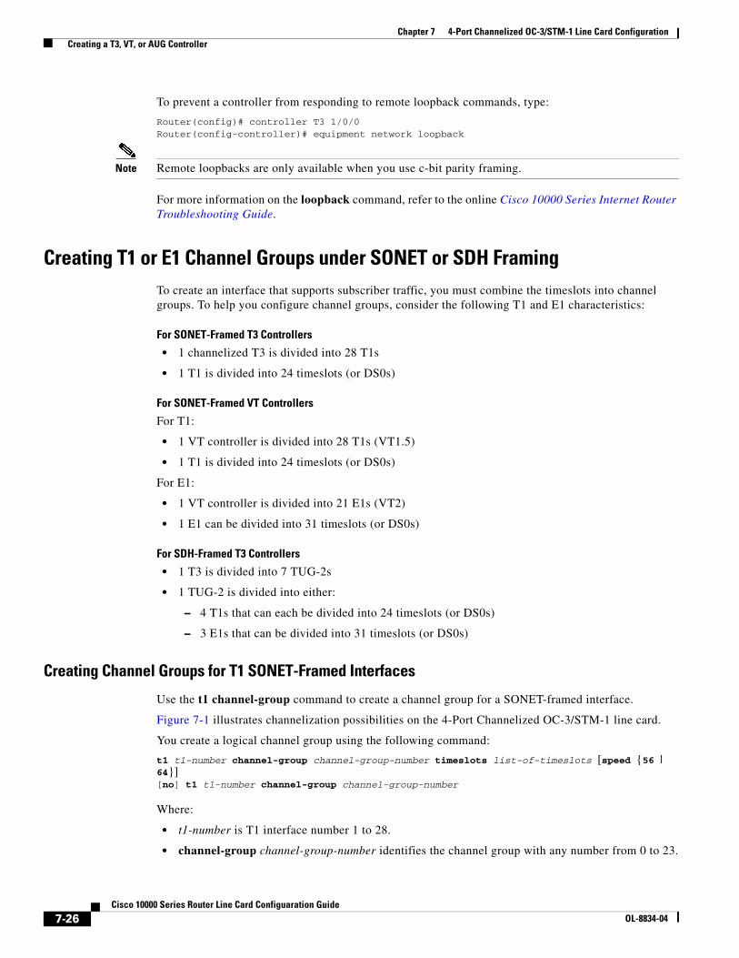
Figure 7-1 Channelization of T3s
Configuring a T3 Interface as Channelized
A T3 interface is channelized by default. Use the channelized command if you had previously made the interface unchannelized.
[no] channelizedchannelized
Caution The no channelized command removes all channel groups from a 4-Port Channelized OC-3/STM-1 line card interface. If you have already configured channel groups, use this command with caution.
The following example shows how to create a 4-Port Channelized OC-3/STM-1 line card interface:
Router(config)# controller T3 1/0/0.1Router(config-controller)# channelized
Setting the Framing Type
To specify a framing type for the channelized T3 controller, use the framing command.
framing [c-bit | m23 | auto-detect][no] framing [c-bit | m23 | auto-detect]
The default is auto-detect.
Use the no form of the command to return the framing type to its default.
You can instruct the 4-Port Channelized OC-3/STM-1 line card to detect the framing type from the far end and transmit that same framing type:
Router(config)# controller T3 1/0/0.1Router(config-controller)# framing auto-detect
T1
T1
T1
T1T1
T1T1
T1
T1
T1T1
T1
T1
T1T1
T1T1
T1
T1
T1T1
T1
T1
T1
T1T1T1
T1
A fully channelized T3can be broken into 28 T1s... ...each of which contains 24 56-KB
(or 64-KB) timeslots (numbered 0 to 23).
Single timeslot
A T1 is broken into channel groupsto provide subscribers with ratesranging from full T1 (all 24 timeslots)to a single DS0 (one timeslot).The gray circles represent a channelgroup containing timeslots 1 to 5.
Channelgroup
3854
4
7-22Cisco 10000 Series Router Line Card Configuaration Guide
OL-8834-04

Chapter 7 4-Port Channelized OC-3/STM-1 Line Card Configuration Creating a T3, VT, or AUG Controller
Entering MDL Messages
You can configure maintenance data link (MDL) messages (as defined in the ANSI T1.107a-1990 specification) on the channelized T3 interface.
Note MDL messages are supported only when the T3 framing is set for C-bit parity. (See the “Setting the Framing Type” section on page 7-22.)
To configure MDL messages, use the mdl command:
mdl {transmit {path | idle-signal | test-signal} | string {eic | lic | fic | unit | pfi | port | generator} id_string}[no] mdl {transmit {path | idle-signal | test-signal} | string {eic | lic | fic | unit | pfi | port | generator} id_string}
Where:
• transmit path enables transmission of the MDL path message
• transmit idle-signal enables transmission of the MDL idle-signal message
• eic is the equipment identification code (up to 10 characters)
• lic is the location identification code (up to 11 characters)
• fic is the frame identification code (up to 10 characters)
• unit is the unit identification code (up to 6 characters)
• pfi is the facility identification code to include in the MDL path message (up to 38 characters)
• port is the equipment port (which initiates the idle signal) to include in the MDL idle signal message (up to 38 characters)
• generator is the generator number to include in the MDL test signal message (up to 38 characters)
The default is that no MDL message is configured.
Use the no form of the command to remove an MDL message.
Examples of configuring MDL messages follow:
• Enable the MDL path message transmission.
Router(config)# controller T3 1/0/0.1Router(config-controller)# mdl transmit path
• Enable the MDL idle signal message transmission.
Router(config-controller)# mdl transmit idle-signal
• Enable the MDL test signal message transmission.
Router(config-controller)# mdl transmit test-signal
• Enter the equipment identification code.
Router(config-controller)# mdl string eic router A
• Enter the location identification code.
Router(config-controller)# mdl string lic test network
• Enter the frame identification code.
Router(config-controller)# mdl string fic building b
7-23Cisco 10000 Series Router Line Card Configuaration Guide
OL-8834-04

Chapter 7 4-Port Channelized OC-3/STM-1 Line Card Configuration Creating a T3, VT, or AUG Controller
• Enter the unit identification code.
Router(config-controller)# mdl string unit abc
• Enter the facility identification code.
Router(config-controller)# mdl string pfi string
• Enter the port number to send in the MDL idle signal message.
Router(config-controller)# mdl string port string
• Enter the generator number to send in the MDL test signal message.
Router(config-controller)# mdl string generator string
Specifying the Idle Pattern
You can set a specific pattern to be transmitted between HDLC packets on all unconfigured timeslot interfaces that belong to a channelized T3 interface. To do so, use the idle pattern command.
idle pattern patterns[no] idle pattern patterns
Where patterns is a number in the range of 0x0 to 0xff (hexadecimal) or 0 to 255 (decimal). You can enter this value in either hexadecimal or decimal form. Values of 0 to 254 set the idle pattern to HDLC flags (0x7e); a value of 255 sets the pattern to 0xff (all ones).
Note Some systems interpret marks, 0xff, as an abort signal. Therefore, flags, 0x7e, is preferred.
The default idle pattern is 0x7e.
Use the no form of the command to return the idle pattern to its default value.
Examples:
• Set a hexadecimal idle pattern.
Router(config)# controller T3 1/0/0.1Router(config-controller)# idle pattern 0x10
• Set a decimal idle pattern.
Router(config)# controller T3 1/0/0.1Router(config-controller)# idle pattern 23
Setting the T3 Clock Source
At the prompt, set the internal or line clock source for the selected T3 controller using the clock source command. This command is set in controller configuration mode.
clock source {internal | line}
Where:
• internal specifies that the internal clock source is used
• line specifies that the network clock source is used
The default is clock source internal.
7-24Cisco 10000 Series Router Line Card Configuaration Guide
OL-8834-04

Chapter 7 4-Port Channelized OC-3/STM-1 Line Card Configuration Creating a T3, VT, or AUG Controller
In this example, a T3 controller is instructed to use a line clock source:
Router(config)# controller T3 1/0/0.1Router(config-controller)# clock source line
Configuring the Loopback Mode for a T3 Controller
You can configure the loopback modes for a T3 controller by using the loopback command:
loopback {local | network | remote}[no] loopback {local | network | remote}
The default is no loopback.
To disable loopback on the T3 controller, use the no form of the command.
Examples:
• Configure a T3 controller for local loopback.
Router(config)# controller T3 1/0/0Router(config-controller)# loopback local
Local loopback simultaneously loops all channels toward the router and transmits a T3 AIS to the network. You can use local loopback to diagnose problems with the port when the port is isolated from the network cables.
• Configure a T3 port for network loopback.
Router(config)# controller T3 1/0/0Router(config-controller)# loopback network
Network loopback loops the T3 line back towards the network and can be used to diagnose problems with cables from the central switching office to the port.
• Configure a T3 port for remote loopback.
Router(config)# controller T3 1/0/0Router(config-controller)# loopback remote
Remote loopback sends a command to loop the T3 line at the far end (central office). It can be used to diagnose problems with cables from the port adapter to the switching office.
Configuring a T3 Controller to Respond to Remote Loopback Commands
Use the equipment loopback command to run loopbacks in conjunction with remote equipment.
equipment [customer | network] loopback
Where:
• customer allows a port to respond to loopback commands from remote T3 equipment.
• network causes a controller to ignore remote T3 loopback commands.
Example:
To enable the controller’s ability to respond to remote loopback requests, type:
Router(config)# controller T3 1/0/0Router(config-controller# equipment customer loopback
7-25Cisco 10000 Series Router Line Card Configuaration Guide
OL-8834-04
Chapter 7 4-Port Channelized OC-3/STM-1 Line Card Configuration Creating a T3, VT, or AUG Controller
To prevent a controller from responding to remote loopback commands, type:
Router(config)# controller T3 1/0/0Router(config-controller)# equipment network loopback
Note Remote loopbacks are only available when you use c-bit parity framing.
For more information on the loopback command, refer to the online Cisco 10000 Series Internet Router Troubleshooting Guide.
Creating T1 or E1 Channel Groups under SONET or SDH FramingTo create an interface that supports subscriber traffic, you must combine the timeslots into channel groups. To help you configure channel groups, consider the following T1 and E1 characteristics:
For SONET-Framed T3 Controllers
• 1 channelized T3 is divided into 28 T1s
• 1 T1 is divided into 24 timeslots (or DS0s)
For SONET-Framed VT Controllers
For T1:
• 1 VT controller is divided into 28 T1s (VT1.5)
• 1 T1 is divided into 24 timeslots (or DS0s)
For E1:
• 1 VT controller is divided into 21 E1s (VT2)
• 1 E1 can be divided into 31 timeslots (or DS0s)
For SDH-Framed T3 Controllers
• 1 T3 is divided into 7 TUG-2s
• 1 TUG-2 is divided into either:
– 4 T1s that can each be divided into 24 timeslots (or DS0s)
– 3 E1s that can be divided into 31 timeslots (or DS0s)
Creating Channel Groups for T1 SONET-Framed Interfaces
Use the t1 channel-group command to create a channel group for a SONET-framed interface.
Figure 7-1 illustrates channelization possibilities on the 4-Port Channelized OC-3/STM-1 line card.
You create a logical channel group using the following command:
t1 t1-number channel-group channel-group-number timeslots list-of-timeslots [speed {56 | 64}][no] t1 t1-number channel-group channel-group-number
Where:
• t1-number is T1 interface number 1 to 28.
• channel-group channel-group-number identifies the channel group with any number from 0 to 23.
7-26Cisco 10000 Series Router Line Card Configuaration Guide
OL-8834-04

Chapter 7 4-Port Channelized OC-3/STM-1 Line Card Configuration Creating a T3, VT, or AUG Controller
• timeslots list-of-timeslots can be 1 to 24 or a combination of subranges within the 1 to 24 interval. You can indicate a range using a hyphen, commas, or a combination of both. One timeslot equals one DS0. (See the examples below.)
• speed{56 | 64} is an optional argument that specifies the speed of a timeslot as either 56 or 64 kbps. The default is 64. (The 56 kbps timeslots are generally used with older T1 equipment that does not support B8ZS line coding and are associated with SF framing.)
Use the no form of the command to remove a logical channel group.
The following examples show how to use the t1 channel-group command:
• In this example, T1 interface 3 includes channel group 20 and consists of 9 channelized timeslots:
Router(config)# controller t3 1/0/0.1Router(config-controller)# t1 3 channel-group 20 timeslots 1-8, 10
To enter interface configuration mode for T1 interface 3 channel group 20, enter the following:
Router(config)# interface serial 1/0/0.1/3:20
• In this example, t1 interface 4 includes channel group 18 and consists of all 24 timeslots, creating a full T1 interface:
Router(config)# controller t3 1/0/0.1Router(config-controller)# t1 4 channel-group 18 timeslots 1-24
To enter interface configuration mode for T1 interface 4 channel group 18, enter the following:
Router(config)# interface serial 1/0/0.1/4:18
• In the following example, T1 interface number 5 is divided into three channel groups, which total 11 timeslots:
Router(config)# controller t3 1/0/0.1Router(config-controller)# t1 5 channel-group 19 timeslots 1-6Router(config-controller)# t1 5 channel-group 20 timeslots 10Router(config-controller)# t1 5 channel-group 21 timeslots 7-9, 24
• In the following example, channel group 20 on T1 1 is removed:
Router(config)# controller T3 1/0/0.1Router(config-controller)# no t1 1 channel-group 20
Creating Channel-Groups for SDH-Framed Interfaces
Channel Limitations
There is a limit of 128 channels per SDH controller, and a maximum of 192 channels for the 4-Port Channelized OC-3/STM-1 line card. This limitation applies to both T1 and E1 interfaces when you create channel groups for controllers.
For example, if you created 128 channels on T1 controller #1 on port 2, and 64 channels on T1 controller #2 on port 2, then you could not create any additional channels on T1 controller #3 or T1 controller #4 because you have reached the maximum limit of 192 channels for a single port (port 2 in this example).
To create a logical channel group, use one of the following commands:
For T1:[no] tug-2 <tug-2#> t1 <t1#> channel-group <channel#> timeslots <range> [speed 64|56]
7-27Cisco 10000 Series Router Line Card Configuaration Guide
OL-8834-04
Chapter 7 4-Port Channelized OC-3/STM-1 Line Card Configuration Creating a T3, VT, or AUG Controller
For E1 (framed):[no] tug-2 <tug-2#> e1 <e1#> channel-group <channel#> timeslots <range>
For E1 (unframed):[no] tug-2 <tug-2#> e1 <e1#> unframed
Where:
• tug-2 is 1 to 7
• t1# is 1 to 4
• e1# is 1 to 3
• channel-group channel# identifies the channel group with any number from 0 to 23.
• timeslots range can be 1 to 24 for T1, or 1 to 31 for E1, or a combination of subranges within those intervals. You can indicate a range using a hyphen, commas, or a combination of both. One timeslot equals one DS0. (See the examples below.)
• speed{56 | 64} is an optional T1 argument that specifies the speed of a timeslot as either 56 or 64 kbps. The default is 64. (The 56 kbps timeslots are generally used with older T1 equipment that does not support B8ZS and are associated with SF framing.)
Note The speed argument applies only to T1 channel groups and is not valid for E1.
• unframed creates an unframed E1 channel. This creates an interface with channel-group number 0.
Note The unframed argument applies only to E1 channel groups and is not valid for T1.
Use the no form of the command to remove a logical channel group.
The following examples show how to use the channel-group command:
• In this example, T1 interface 3 includes channel group 20 and consists of 9 channelized timeslots:
Router(config-controller)# controller au-3 2/0/0.2Router(config-controller)# mode c-11Router(config-controller)# tug-2 1 t1 3 channel-group 20 timeslots 1-9
To enter interface configuration mode for T1 interface 3 channel group 20, enter the following:
Router(config)# interface serial 2/0/0.2/3:20
• In this example, T1 interface 4 includes channel group 18 and consists of all 24 timeslots, creating a full T1 interface:
Router(config-controller)# controller au-3 2/0/0.2Router(config-controller)# mode c-11Router(config-controller)# tug-2 1 t1 4 channel-group 18 timeslots 1-24
To enter interface configuration mode for T1 interface 4 channel group 18, enter the following:
Router(config)# interface serial 2/0/0.2/4:18
• In the following example, T1 interface number 5 is divided into three channel groups, which total 11 timeslots:
Router(config-controller)# controller au3 2/0/0.2Router(config-controller)# mode c-11Router(config-controller)# tug-2 1 t1 5 channel-group 19 timeslots 1-6
7-28Cisco 10000 Series Router Line Card Configuaration Guide
OL-8834-04

Chapter 7 4-Port Channelized OC-3/STM-1 Line Card Configuration Creating a T3, VT, or AUG Controller
Router(config-controller)# tug-2 1 t1 5 channel-group 20 timeslots 10Router(config-controller)# tug-2 1 t1 5 channel-group 21 timeslots 7-9, 24
• In the following example, channel group 20 is removed:
Router(config-controller)# controller au3 2/0/0.2Router(config-controller)# no tug-2 1 t1 5 channel-group 20
Channelized T1 Commands under SONET or SDH FramingYou can enter commands to modify aspects of a T1 interface from controller configuration mode for a T3 interface. This section describes the commands for:
• Setting the Framing Format, page 7-29
• Controlling Yellow Alarms, page 7-30
• Setting the T1 Clock Source, page 7-30
• Configuring FDL, page 7-30
• Configuring a T1 BER Test, page 7-31
• Configuring Loopback Mode, page 7-31
After you configure a T1 interface, you can add encapsulation, routing, and other instructions by entering interface configuration mode. For example:
Router(config)# interface serial 1/0/0.1/4:18
Setting the Framing Format
You can specify the T1 interface framing format using the following command:
t1 t1-number framing {esf | sf [hdlc-idle {0x7E | 0xFF}]} [no] t1 t1-number framing {esf | sf [hdlc-idle {0x7E | 0xFF}]}
Where:
• t1-number is T1 interface 1 to 28
• framing is either extended super frame (ESF) or super frame (SF). You can set SF hdlc-idle to 0x7E or 0xFF
• hdlc-idle options allow you to set the idle pattern for the T1 interface to either 0x7e (the default) or 0xFF
The default framing format is extended super frame (ESF).
Use the no form of the command to return framing to its default value.
Examples:
• Set SF framing format for T1 interface 6.
Router(config)# controller T3 1/0/0.1Router(config-controller)# t1 6 framing sf
• Set ESF framing format for T1 interface 16:
Router(config)# controller T3 1/0/0.1Router(config-controller)# t1 16 framing esf
7-29Cisco 10000 Series Router Line Card Configuaration Guide
OL-8834-04

Chapter 7 4-Port Channelized OC-3/STM-1 Line Card Configuration Creating a T3, VT, or AUG Controller
Controlling Yellow Alarms
Use the t1 yellow command to turn the detection or generation of a yellow alarm on or off.
t1 t1-number yellow {detection | generation}[no] t1 t1-number yellow {detection | generation}
Where:
• t1-number is T1 interface 1 to 28
• detection means that the interface is told that it is failing by the remote device, causing Cisco IOS software to send a message to the console
• generation means that the interface notifies the remote device if it is failing, causing Cisco IOS software to send a message to the console
When you select SF framing for a full T1 interface (24 timeslots) that uses the default speed of 64, consider using the no t1-number yellow detection command to turn off yellow alarm detection, because the yellow alarm can be incorrectly detected with SF framing.
In the following example, T1 interface 1 is set to yellow detection:
Router(config)# controller t3 2/0/0.1Router(config-controller)# t1 1 yellow detection
Setting the T1 Clock Source
You can set the internal or line (network) clock source for a T1 interface using the controller command.
t1 t1-number clock source {internal | line}
Where:
• t1-number is T1 interface 1 to 28
• internal specifies that the internal clock source is used
• line specifies that the network clock source is used
The default is clock source internal.
In the following example, the interface is instructed to get its clock source from the line:
Router(config)# controller T3 1/0/0.1Router(config-controller)# t1 1 clock source line
Configuring FDL
You can use the fdl ansi command to enable 1-second transmissions of ANSI T1.403 performance reports through the facility data link (FDL), on both ends of the T1 connection.
t1 t1-number fdl ansi[no] t1 t1-number fdl ansi
Where t1-number is T1 interface 1 to 28.
Use the no form of the command to disable this feature.
Note You can use this command only when the T1 framing is ESF.
7-30Cisco 10000 Series Router Line Card Configuaration Guide
OL-8834-04
Chapter 7 4-Port Channelized OC-3/STM-1 Line Card Configuration Creating a T3, VT, or AUG Controller
In the following example, FDL is enabled:
Router(config)# controller t3 1/0/0.1Router(config-controller)# t1 2 fdl ansi
Configuring a T1 BER Test
You can configure an individual T1 interface to run an independent BER test. The test is used to check cables and solve signal problems in the field. To send a BER test pattern on a T1 interface, use the following command:
t1 t1-number bert pattern pattern interval time [unframed][no] t1 t1-number bert
Where:
• t1-number is T1 interface number 1 to 28
• time is 1 to 14,400 minutes
• pattern is
– 2^11—pseudorandom test pattern (2048 bits in length)
– 2^15—pseudorandom O.151 test pattern (32,768 bits in length)
– 2^20-O153—pseudorandom O.153 test pattern (1,048,575 bits in length)
• unframed causes the BER test pattern to use the entire T1 bandwidth, including the T1 framing and payload bits. If unframed is omitted, the T1 is either SF or ESF framed as configured by the T1 n framing command, and the BER test pattern occupies only the T1 payload bits.
Note For each T3, you can run only one BER test at a time.
You can terminate a BER test at any time using the no form of the command.
For more information, refer to the online Cisco 10000 Series Internet Router Troubleshooting Guide.
Example:
• Send a BER test pseudorandom pattern of 2^15 through T1 interface 10 for 5 minutes.
Router(config)# controller T3 1/0/0.1Router(config-controller)# t1 10 bert pattern 2^15 interval 5 unframed
Configuring Loopback Mode
If a problem occurs when you configure a T1 interface, you can troubleshoot the line card by using the following command from controller configuration mode:
t1 t1-number loopback [local | network {line | payload} | remote [line [fdl {ansi | bellcore}] | payload [fdl | ansi]]][no] t1 t1-number loopback [local | network {line | payload} | remote [line [fdl {ansi | bellcore}] | payload [fdl | ansi]]]
Where:
• t1-number is T1 interface 1 to 28.
• local loops the router output data back toward the router at the T1 framer and sends an alarm indication signal (AIS) out toward the network.
7-31Cisco 10000 Series Router Line Card Configuaration Guide
OL-8834-04

Chapter 7 4-Port Channelized OC-3/STM-1 Line Card Configuration Creating a T3, VT, or AUG Controller
• network {line | payload} loops the data back toward the network and automatically sets a local loopback at the HDLC controllers (line) or loops the payload data back toward the network and automatically sets a local loopback at the HDLC controllers (payload).
• remote line fdl {ansi | bellcore} sends a repeating, 16-bit ESF data link keyword to the remote end, requesting that it enter into a network line loopback. You can specify an ANSI or Bellcore keyword.
• remote payload [fdl] [ansi] sends a repeating, 16-bit ESF data link code word to the remote end, requesting entry into a network payload loopback. Using fdl and ansi enables the remote payload facility data link (FDL) ANSI bit loopback on the T1 channel.
Use the no form of the command to terminate a loopback.
For more information on this command, refer to the online Cisco 10000 Series Internet Router Troubleshooting Guide.
Examples:
• Configure the T3 controller for local loopback on T1 interface 1.
Router(config)# controller t3 1/0/0.1Router(config-controller)# t1 1 loopback local
• Configure the T3 controller for remote FDL ANSI loopback on T1 interface 1.
Router(config)# controller t3 1/0/0.1Router(config-controller)# t1 1 loop remote line fdl ansi
7-32Cisco 10000 Series Router Line Card Configuaration Guide
OL-8834-04


![SonetExpert™ Channelized Analyzer...6 Main Features… •Scans the received STM-4/STM-1 traffic and identifies the mapping, tributary type [T1/E1], equipped/unequipped status of](https://img.pdfslide.us/doc/110x75/5faa757c67d2b2363f7d8338/sonetexperta-channelized-analyzer-6-main-features-ascans-the-received-stm-4stm-1.jpg)