Embed Size (px)
Citation preview
April 18, 2023 1
Observational Astronomy
Direct imagingPhotometry
Kitchin pp. 329-340, 357-366
2
Astronomical Imaging
or
Specific goal: As many objects as possible (e.g.
clusters, star-forming regions) As large range of surface brightness
as possible (e.g. galaxies)
3
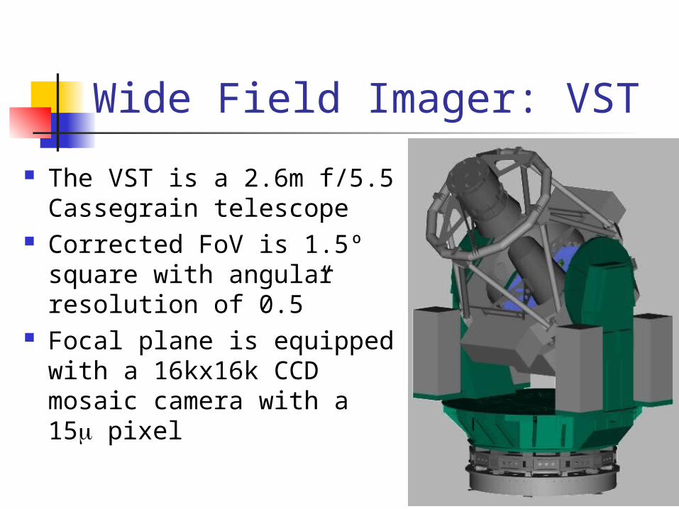
Wide Field Imager: VST
The VST is a 2.6m f/5.5 Cassegrain telescope
Corrected FoV is 1.5º square with angular resolution of 0.5”
Focal plane is equipped with a 16kx16k CCD mosaic camera with a 15 pixel
4
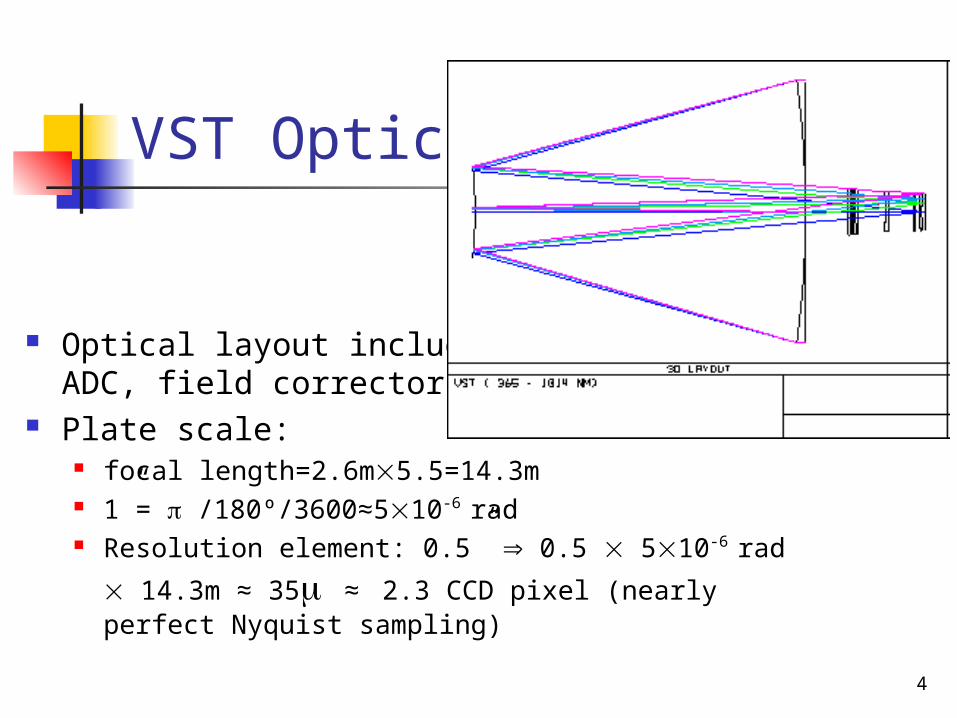
VST Optics
Optical layout includingADC, field corrector etc.
Plate scale: focal length=2.6m5.5=14.3m 1”= /180º/3600≈510-6 rad Resolution element: 0.5” 0.5 510-6 rad 14.3m
≈ 35 ≈ 2.3 CCD pixel (nearly perfect Nyquist sampling)
5
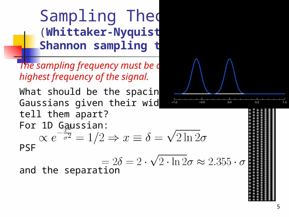
Sampling Theorem(Whittaker-Nyquist-Kotelnikov-Shannon sampling theorem)
The sampling frequency must be at least twice the highest frequency of the signal.
What should be the spacing between two Gaussians given their width so that we can tell them apart?For 1D Gaussian:
PSF
and the separation
6
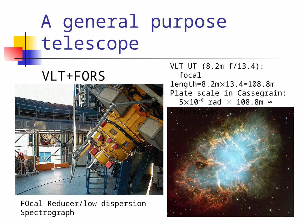
A general purpose telescope
VLT+FORS
FOcal Reducer/low dispersion Spectrograph
VLT UT (8.2m f/13.4): focal length=8.2m13.4=108.8mPlate scale in Cassegrain: 510-6 rad 108.8m ≈ 530/arcsec
7
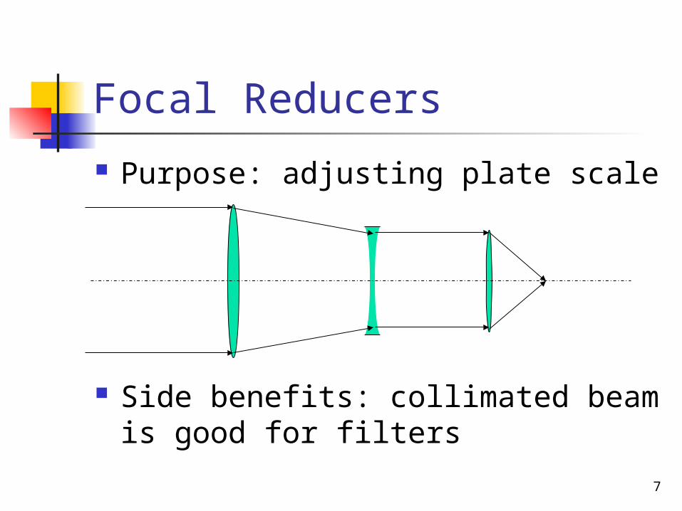
Focal Reducers
Purpose: adjusting plate scale
Side benefits: collimated beam is good for filters
8
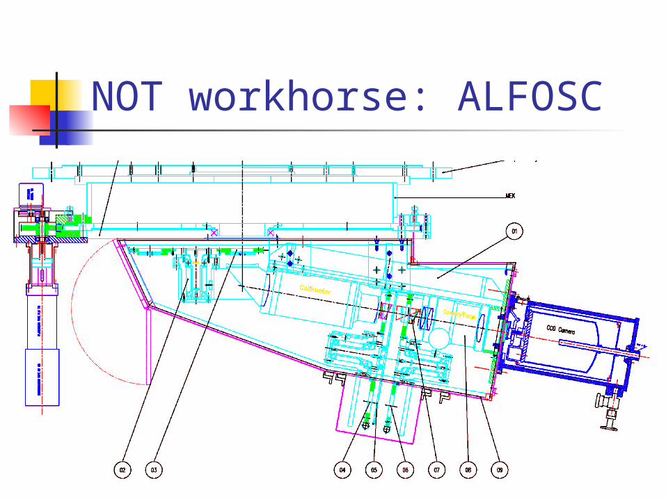
NOT workhorse: ALFOSC
9
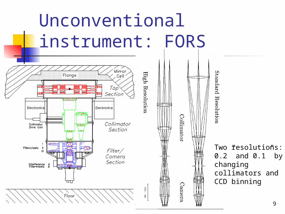
Unconventional instrument: FORS
Two resolutions: 0.2” and 0.1” by changing collimators and CCD binning
10
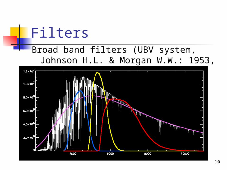
FiltersBroad band filters (UBV system, Johnson
H.L. & Morgan W.W.: 1953, ApJ, 117, 313)
11
Broad-Band Filter Technology
Color absorption glasses: blocking (high absorption shorter
than certain wavelength while highly transparent at longer wavelengths) or
bell-curve (sharp cut-off at shorter wavelength and gradual drop towards longer wavelength)
Transmission is high, up to 75-90%
12
Narrow-Band Filter Technology
Interference coatings: Multiple (up to 20) dielectric layers
producing interference between internal reflections
Create multiple transparency windows at different wavelengths
Must be combined with broad-band filters
Transmission is low, around 20-30%
13
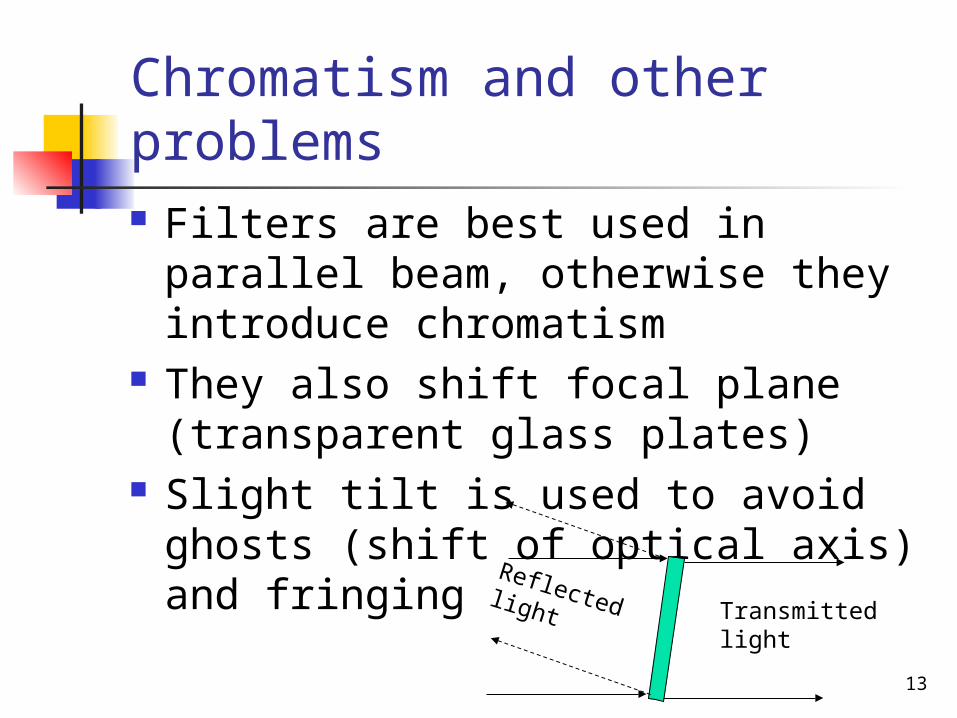
Chromatism and other problems Filters are best used in parallel
beam, otherwise they introduce chromatism
They also shift focal plane (transparent glass plates)
Slight tilt is used to avoid ghosts (shift of optical axis) and fringing
Transmitted light
Reflected light
14
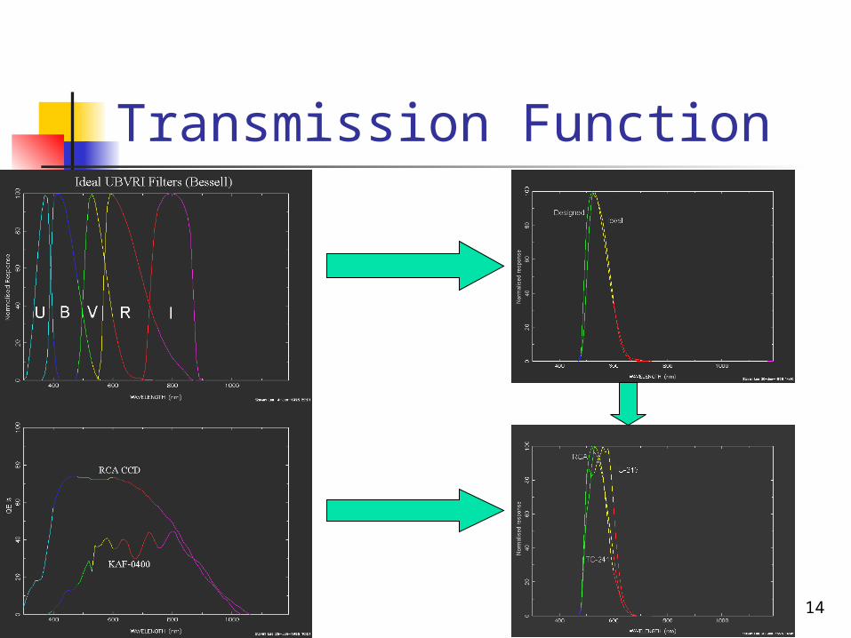
Transmission Function
15
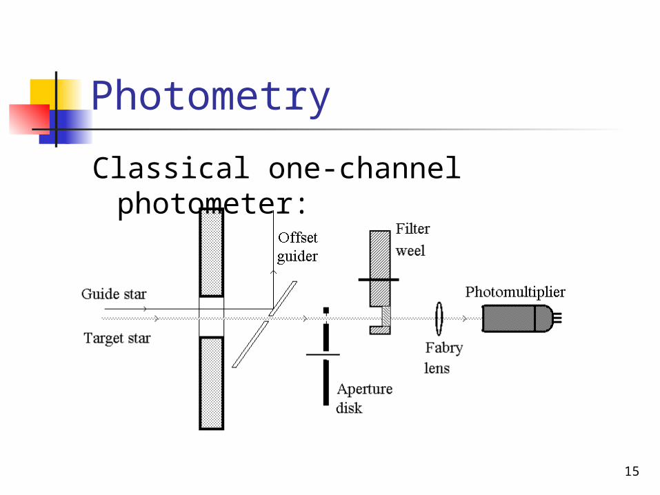
Photometry
Classical one-channel photometer:
16
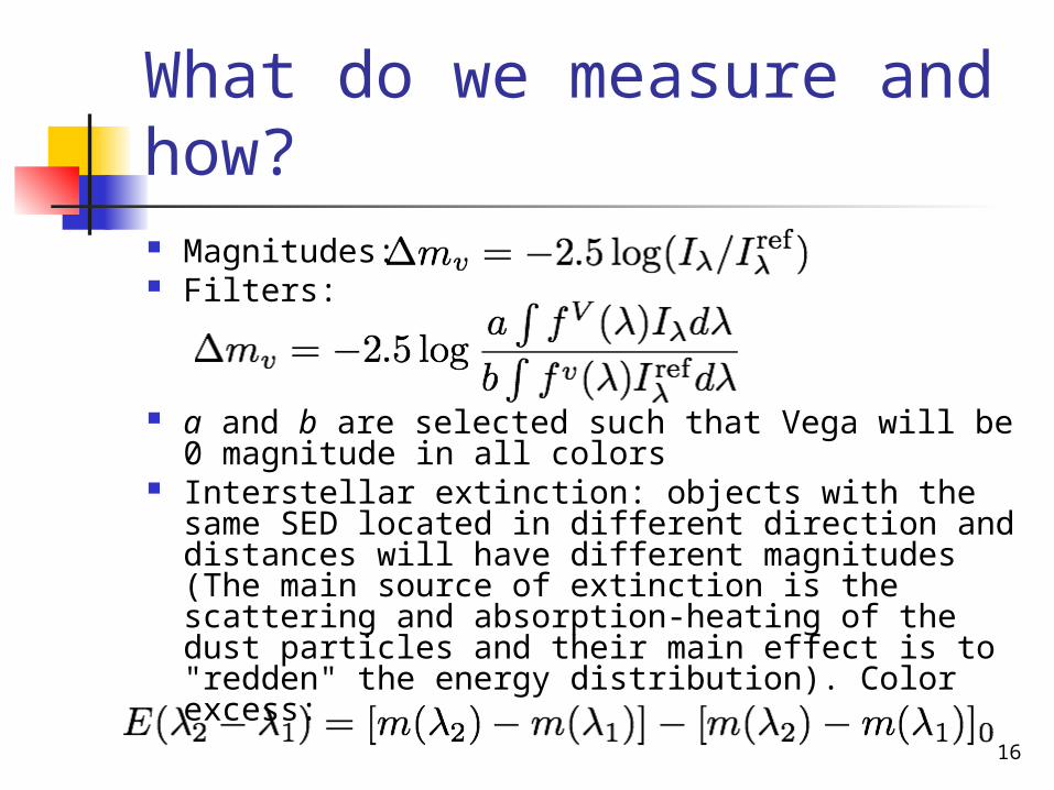
What do we measure and how? Magnitudes: Filters:
a and b are selected such that Vega will be 0 magnitude in all colors
Interstellar extinction: objects with the same SED located in different direction and distances will have different magnitudes(The main source of extinction is the scattering and absorption-heating of the dust particles and their main effect is to "redden" the energy distribution). Color excess:
19
Absolute and differential photometry
Radiation in a given band is affected by the atmosphere, telescope, photometer and detector. All of these must be calibrated.
Absolute photometry is done either from space or with absolute calibration e.g. against a black body standard source.
20
Absolute and differential photometry (cont’d) Once absolute measurements are done
for a few objects they can be used as standards.
Differential photometry measures flux difference in a given band between a target and a standard.
Observations should be close on the sky and in time.
Classical sequence:<selecting band>:<standard> - <target> - <standard>
21
CCD Photometry
Many objects at once (standards and targets)
Large dynamic rangePSF is spread over several pixelsPixels have different sensitivity
and color sensitivity Photometry of extended sources
22
Next time…
Telescopes in Space by Oleg Kochukhov