Embed Size (px)
Citation preview
page 4-1
4. Construction Impacts
Exposition Corridor Transit Project Phase 2 DEIR January 2009
4. CONSTRUCTION IMPACTS
4.1 Introduction
This section identifies the impacts associated with construction of the Exposition Corridor Transit Project Phase 2 (Expo Phase 2) project. The impacts described in this section would only occur during construction, and would be temporary and short-term since construction activities are anticipated to occur over a period of approximately four years.
The development for the Light-Rail Transit (LRT) Alternatives would employ conventional construction methods, techniques, and equipment. All work for development of the transit system would conform to accepted industry specifications and standards, including Best Management Practices (BMP). Project engineering and construction would, at minimum, be completed in conformance with the following regulations, guidelines, and criteria:
• Metro Design Criteria
• California Building Code
• Standard for Fixed Guideway Transit and Passenger Rail Systems
• National Electrical Code (NFPA 70)
• American Railway Engineering and Maintenance of Way Association Standards (AREMA)
• Metro Operating Rules
• Expo Fire/Life Safety Design Criteria
• California, Public Utility Commission (CPUC) General Orders (Including but not limited to 88, 95, 143-B, and 164-D)
• Metro Sustainability Guidelines
• South Coast Air Quality Management District (SCAQMD) Rule 403
• SCAQMD Clean Air Act Rule 1403—asbestos regulation
• National Pollutant Discharge Elimination System (NPDES)
• Standard Urban Stormwater Mitigation Plan (SUSMP)
• Stormwater Pollution Prevention Plan (SWPPP)
Major elements of the project include the demolition and grading of the existing Exposition ROW and acquisition areas, and construction of guideways and trackwork, at-grade and aerial station platforms, grade separations, roadway improvements, and a maintenance facility.
During the period of construction, currently planned to be from 2011 through 2015 the number of workers on site at any one time will vary depending on the activity. It is expected to reach between 250 and 300 at the peak of construction in approximately 2012/2013.
Full bibliographic references can be found in Appendix B (Bibliography).
page 4-2
4. Construction Impacts
Exposition Corridor Transit Project Phase 2 DEIR January 2009
4.2 Construction Scenario
This section provides an overview of the typical construction activities that would occur to build an LRT system. These methods are consistent with how Expo Phase 1 and other Metro projects have been built. Actual construction methods and materials may vary, depending in part on how contractors choose to implement their work to be most cost-effective, within the parameters set forth in bid, contract, and construction documents, and to comply with mitigation requirements.
The major construction activities include guideway construction (at-grade, aerial, retained-fill); station construction (at-grade, aerial); systems installation; construction of other facilities including parking, and a maintenance facility; as well as associated street widening and reconstruction, demolition, and utility relocation and installation work. This chapter notes the locations of the construction activities based on conceptual engineering design (Appendix E [Plans and Profiles] and Appendix F [Station Plans and Maintenance Facility]) and anticipated typical construction methods and equipment. The likely street/lane closures, construction staging areas, and haul routes are identified and an estimate of the construction schedule and staffing is also provided.
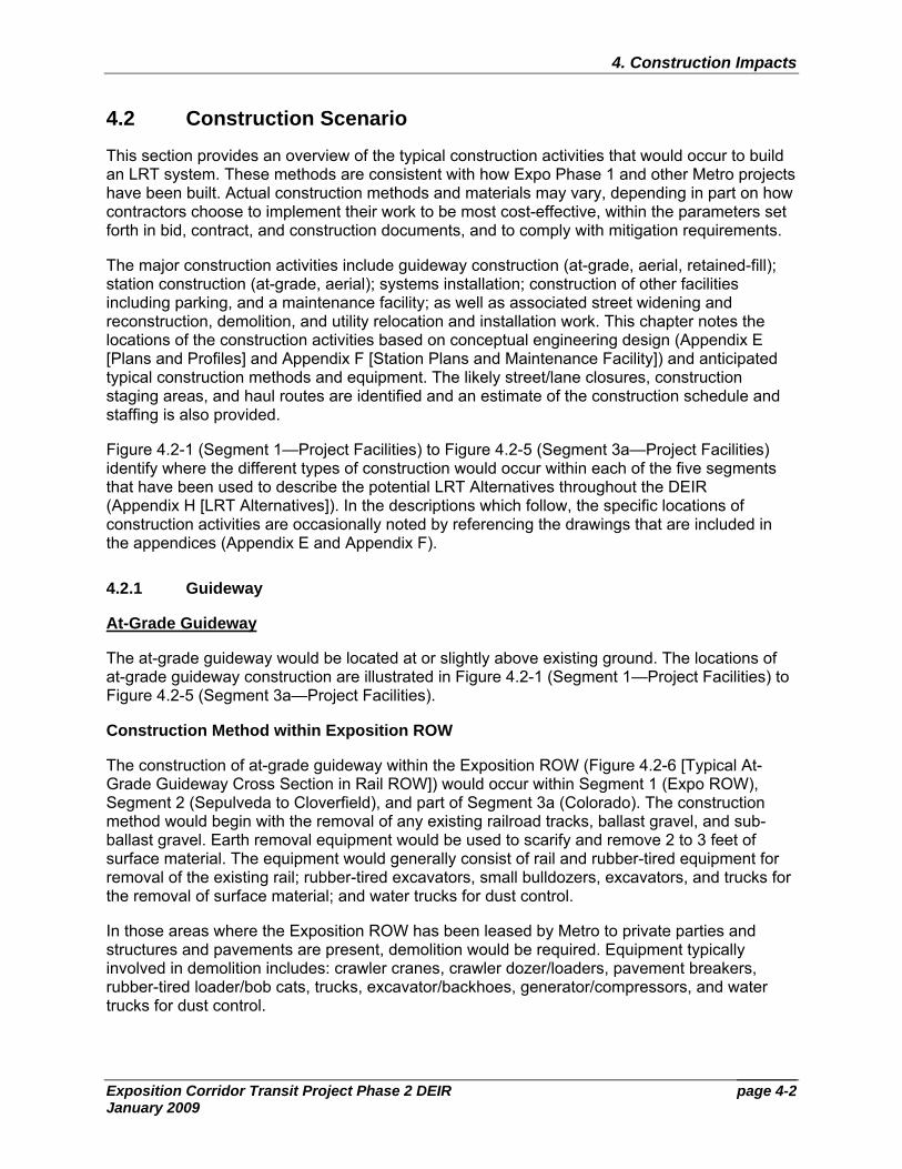
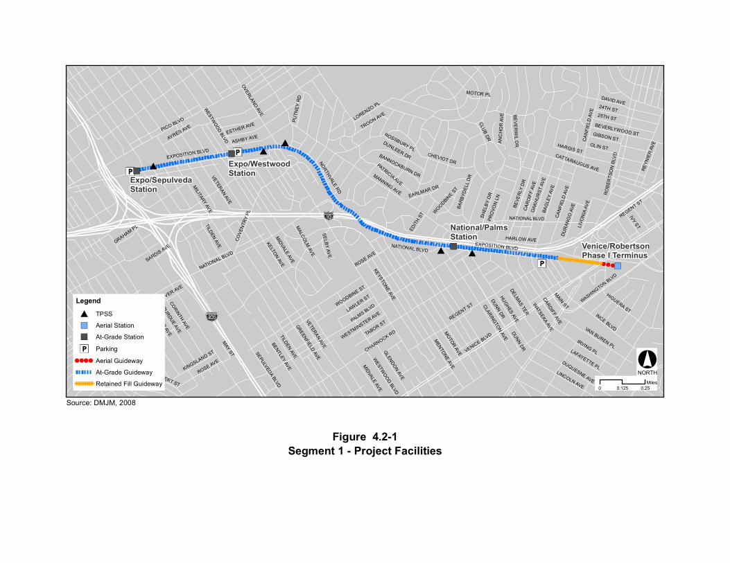
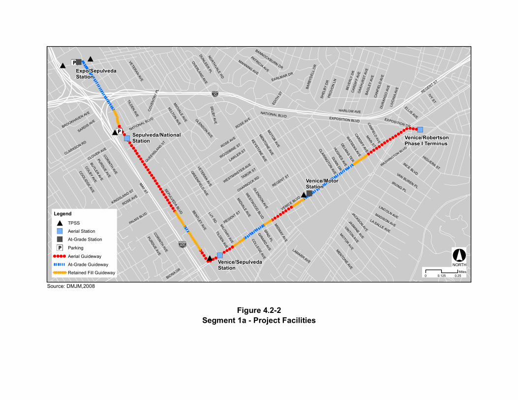
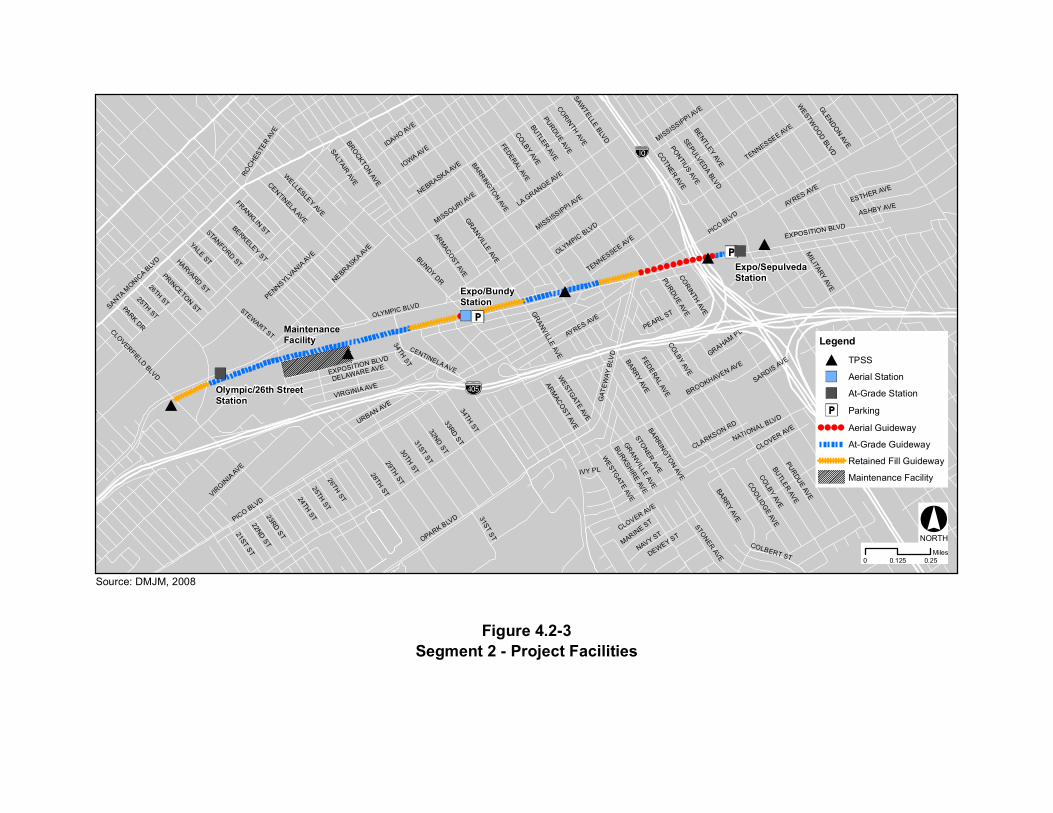
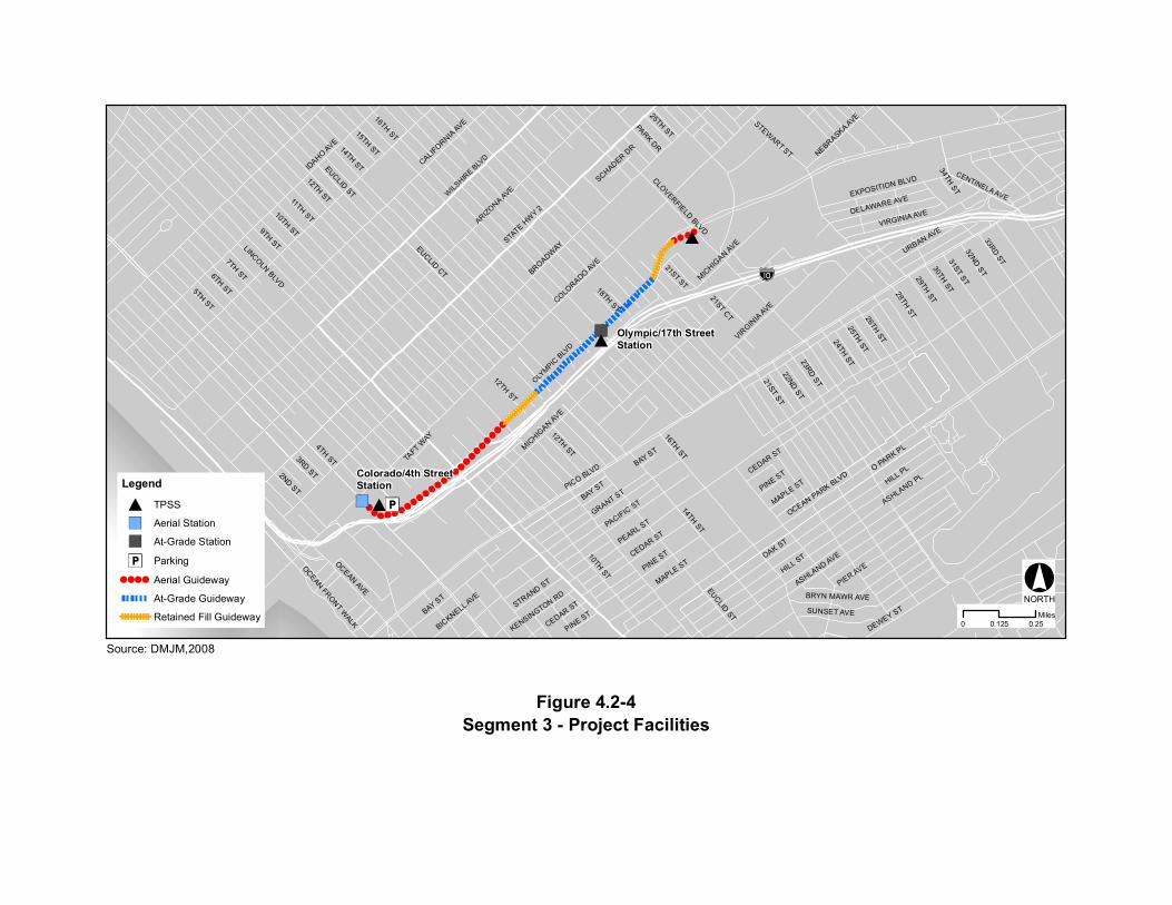
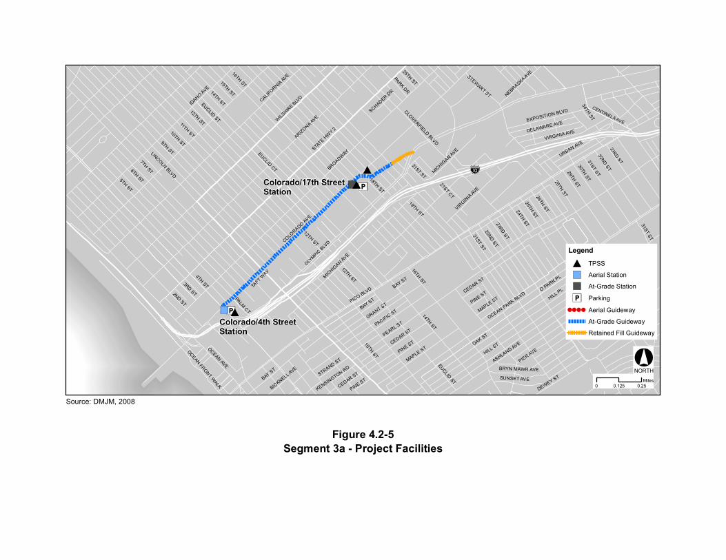
Figure 4.2-1 (Segment 1—Project Facilities) to Figure 4.2-5 (Segment 3a—Project Facilities) identify where the different types of construction would occur within each of the five segments that have been used to describe the potential LRT Alternatives throughout the DEIR (Appendix H [LRT Alternatives]). In the descriptions which follow, the specific locations of construction activities are occasionally noted by referencing the drawings that are included in the appendices (Appendix E and Appendix F).
4.2.1 Guideway
At-Grade Guideway
The at-grade guideway would be located at or slightly above existing ground. The locations of at-grade guideway construction are illustrated in Figure 4.2-1 (Segment 1—Project Facilities) to Figure 4.2-5 (Segment 3a—Project Facilities).
Construction Method within Exposition ROW
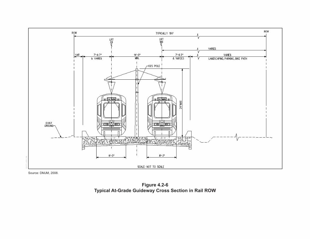
The construction of at-grade guideway within the Exposition ROW (Figure 4.2-6 [Typical At-Grade Guideway Cross Section in Rail ROW]) would occur within Segment 1 (Expo ROW), Segment 2 (Sepulveda to Cloverfield), and part of Segment 3a (Colorado). The construction method would begin with the removal of any existing railroad tracks, ballast gravel, and sub-ballast gravel. Earth removal equipment would be used to scarify and remove 2 to 3 feet of surface material. The equipment would generally consist of rail and rubber-tired equipment for removal of the existing rail; rubber-tired excavators, small bulldozers, excavators, and trucks for the removal of surface material; and water trucks for dust control.
In those areas where the Exposition ROW has been leased by Metro to private parties and structures and pavements are present, demolition would be required. Equipment typically involved in demolition includes: crawler cranes, crawler dozer/loaders, pavement breakers, rubber-tired loader/bob cats, trucks, excavator/backhoes, generator/compressors, and water trucks for dust control.
WESTW
OO
D BLVD
PALMS BLVD
NATIONAL BLVD
WASHINGTON BLVD
Expo/SepulvedaStation
National/PalmsStation
Venice/RobertsonPhase I Terminus
Expo/WestwoodStation
OVERLAND AVE
MO
TOR AVE
MANNING AVE RO
BER
TSO
N B
LVD
MILITARY AVE
NATIONAL BLVD
KELTON AVE
CLUB DR
VETERAN AVE
TABOR ST
BUTLER AVE
BAG
LEY
AVE
CHEVIOT DR
GREENFIELD AVE
BENTLEY AVE
DUQUESNE AVE
EXPOSITION BLVDCATTARAUGUS AVE
INCE BLVD
AYRES AVE
DUNN DR
CA
NFI
ELD
AV
E
HUGHES AVE
TILDEN AVE
DAVID AVE
IRVING PL
24TH ST
COVE
NTR
Y PL
25TH ST
NORTHVALE RD
CLARINGTO
N AVE
HIGUERA ST
ESTHER AVE
CA
RD
IFF
AVE
DUNLEER DR
LINCOLN AVE
MIDVALE AVE
WESTMINSTER AVE
BEVE
RLY
DR
ASHBY AVE
EARLMAR DR
HARGIS ST
OA
KH
UR
ST A
VE
VAN BUREN PLLAFAYETTE PL
BEVERLYWOOD STTROON AVE
PURDUE AVE
SHEL
BY
DR
REGENT ST
ANC
HO
R A
VE
CORINTH AVE
HARLOW AVE
MALC
OLM
AVE
WATSEKA AVE
OLIN ST
IVY ST
KINGSLAND ST
RE
YNIE
R A
VE
LORENZO PL
COLBERT ST
BAR
BYD
ELL
DR
WESTW
OO
D BLVD
PUTN
EY R
D
GIBSON ST
LIVO
NIA
AV
E
LAWLER ST
EDIT
H ST
GRAHAM PL
BANNOCKBURN DR
ROSSBURY PL
MOTOR PL
DELMAS TER
PRO
VON
LN
SARDIS AVE
TILDEN AVE
PICO BLVD
MENTO
NE AVE
KEYSTONE AVE
MIDVALE AVE
WOODBIN
E ST
DU
RAN
GO
AVE
CA
NFI
ELD
AV
E
SEPULVEDA BLVD
REGENT ST
EXPOSITION BLVD
PATRICIA AVE
ROSE AVE
NATIONAL BLVD
CHARNOCK RD
SELBY AV
E
MAIN ST
BE
VE
RW
IL DR
WOODBINE ST
GLENDON AVE
CLOVER AVE
ROSE AVE
MAY ST
DUNN DR
VETERAN AVE
VENICE BLVD
CARDIFF AVE
Segment 1 - Project Facilities
Source: DMJM, 2008
Figure 4.2-1
Legend
TPSS
Aerial Station
At-Grade Station
Parking
Aerial Guideway
At-Grade Guideway
Retained Fill Guideway0 0.250.125
Miles
NORTH
BEVE
RLY
DR
PALMS BLVD
QUEENSLAND S
T
MILITARY AVE
CANFIELD AVE
WASHINGTON BLVD
OVERLAND AVE
MO
TOR AVE
MANNING AVE
NATIONAL BLVD
KELTON AVE
VETERAN AVE
TABOR ST
BUTLER AVE
BAG
LEY
AVE
GREENFIELD AVE
BENTLEY AVE
JASMINE AVE
VINTON AVEINCE BLVD
DUNN DRHUG
HES AVE
TILDEN AVE
IRVING PL
COVE
NTR
Y PL
MADISON AVE
NORTHVALE RD
BROOKHAVEN AVE
CLARINGTO
N AVE
HIGUERA ST
CA
RD
IFF
AVE
LINCOLN AVELA SALLE AVE
MIDVALE AVE
MENTONE AVE
MIDW
AY AVE
WESTMINSTER AVECOLBY AVE
EARLMAR DR
OA
KH
UR
ST A
VE
VAN BUREN PL
PURDUE AVE
SHEL
BY
DR
REGENT ST
CORINTH AVE
HARLOW AVE
BIONA DR
SPAD PL
WATSEKA AVE
IVY ST
KINGSLAND ST
GIRARD AVE
DUNLEER PLBA
RB
YDE
LL D
R
WESTW
OO
D BLVD
ELLIS AVE
LIVO
NIA
AV
E
LUY RD
EXPOSITION DR
LAWLER ST
EDIT
H ST
LAMARR AVE
BANNOCKBURN DR
DELMAS TER
CLARKSON RD
PRO
VON
LN
COLLEG
E AVE
SARDIS AVE
TILDEN AVE
MOTOR AVE
MENTO
NE AVE
CORINTH AVE
REGENT ST
KEYSTONE AVE
MIDVALE AVE JACKSON AVE
DU
RAN
GO
AVE
CA
NFI
ELD
AV
E
SEPULVEDA BLVD
ROSE AVE
REGENT ST
EXPOSITION BLVDGLENDON AVE
COO
LIDGE AVE
PATRICIA AVE
ROSE AVE
NATIONAL BLVD
CHARNOCK RD
SELBY AV
E
PURDUE AVE
MAIN ST
WOODBINE ST
GLENDON AVE
CLOVER AVE
ROSE AVE
MAY ST
VETERAN AVE
VENICE BLVD
CARDIFF AVE
Venice/MotorStation
Expo/SepulvedaStation
Venice/SepulvedaStation
Sepulveda/NationalStation Venice/Robertson
Phase I Terminus
Segment 1a - Project Facilities
Source: DMJM,2008
Figure 4.2-2
Legend
TPSS
Aerial Station
At-Grade Station
Parking
Aerial Guideway
At-Grade Guideway
Retained Fill Guideway0 0.250.125
Miles
NORTH
CENTINELA AVE
OLYMPIC BLVDSTEWART ST
BARRINGTON AVE
FEDERAL AVE
26TH ST
ARMACOST AVE
MaintenanceFacility
PICO BLVD
OLYMPIC BLVD
SAWTELLE BLVD
BUNDY DR
BARRINGTO
N AVE
YALE ST
MILITARY AVE
NATIONAL BLVD
TENNESSEE AVE
IOWA AVE COTNER AVE
23RD ST
28TH ST
BUTLER AVE
IDAHO AVE
STANFORD ST
CLOVERFIELD BLVD
FEDERAL AVE
21ST ST22ND ST
31ST ST29TH ST30TH ST
BROCKTON AVE
GLENDON AVE
34TH ST32ND ST
26TH ST
33RD ST
PRINCETON ST
EXPOSITION BLVD
PICO BLVD
AYRES AVE
STONER AVE
BROOKHAVEN AVE
NAVY ST
NEBRASKA AVE
ESTHER AVE
GAT
EWAY
BLV
D
CHELSEA AVE
ARMACO
ST AVE
COLBY AVE
CENTINELA AVE
ASHBY AVE
PURDUE AVE
PONTIUS AVE
BARRY AVE
URBAN AVE
OPARK BLVD
DELAWARE AVESEPULVEDA BLVD
WELLESLEY AVE
COLBERT ST
MISSISSIPPI AVE
MARINE ST
BURKSHIRE AVE
Exit 1B
PARK DR
GRAHAM PL
LA GRANGE AVE
WESTG
ATE AVE
CLARKSON RD
PENNSYLVANIA AVE
IVY PL
CLOVER AVE
SARDIS AVE
EXPOSITION BLVD
MISSISSIPPI AVE
GRANVILLE AVE
GRANVILLE AVEVIRGINIA AVE
ALLEY
SANTA M
ONICA B
LVD
BUTLER AVE
HARVARD ST
COLBY AVE
VIRGIN
IA AVE
AYRES AVE
PURDUE AVE
PEARL ST
FRANKLIN ST
STONER AVE
TENNESSEE AVE
BARRY AVE
WESTW
OOD BLVD
BENTLEY AVE
GRANVILLE AVE
ROCHES
TER
AVE
SALTAIR AVE
CORINTH AVE
25TH ST
MISSOURI AVE
34TH ST
BERKELEY ST
DEWEY ST
NEBRASKA AVE
24TH ST
COO
LIDGE AVE
COLBY AVE
31ST ST
25TH ST
CLOVER AVE
CORINTH AVE
WESTG
ATE AVE
PURDUE AVE
Expo/BundyStation
Expo/SepulvedaStation
Olympic/26th StreetStation
Segment 2 - Project Facilities
Source: DMJM, 2008
Figure 4.2-3
Legend
TPSS
Aerial Station
At-Grade Station
Parking
Aerial Guideway
At-Grade Guideway
Retained Fill Guideway
Maintenance Facility
0 0.250.125Miles
NORTH
33RD ST
WILSHIRE B
LVD
CENTINELA AVE
21ST ST
OLYMPIC
BLV
D
11TH ST
BUNDY DR
4TH ST
PEARL ST
PICO BLVD
14TH ST
16TH ST
BROADWAY
COLORADO AVE
OCEAN PARK BLVD
HILL STOAK ST
HILL PL
7TH ST6TH ST5TH ST
O PARK PL
ASHLAND AVE
23RD ST
ASHLAND PL
28TH ST
CLOVERFIELD BLVD
OCEAN AVE
21ST ST22ND ST
STEWART ST
31ST ST29TH ST30TH ST
PINE ST
OCEAN FRONT WALK
PIER AVE
MAPLE ST
32ND ST
26TH ST
PACIFIC ST
CEDAR ST
NEBRASKA AVE
STATE H
WY 2
GRANT ST
9TH ST
12TH ST
10TH ST
LINCOLN BLVD
BICKNELL A
VE
MICHIG
AN AVEURBAN AVE
EUCLID ST
EUCLID CT
DELAWARE AVE
SUNSET AVE
BRYN MAWR AVE
BAY ST
STRAND ST
21ST CT
PARK DR
ARIZONA AVE
KENSINGTON RD
TAFT W
AY
SCHADER DR
EXPOSITION BLVD
VIRGINIA AVE
VIRGIN
IA AVE
PINE STBAY ST
DEWEY ST
CEDAR ST
MAPLE ST
15TH ST
PINE ST
25TH ST
14TH ST
CALIFORNIA AVE
34TH ST
18TH ST
24TH ST
IDAHO AVE
3RD ST
CEDAR ST
12TH ST
10TH ST
BAY ST
2ND ST
16TH ST
25TH ST
MICHIG
AN AVE
12TH ST
EUCLID ST
Olympic/17th StreetStation
Colorado/4th StreetStation
Segment 3 - Project FacilitiesFigure 4.2-4
Legend
TPSS
Aerial Station
At-Grade Station
Parking
Aerial Guideway
At-Grade Guideway
Retained Fill Guideway0 0.250.125
Miles
NORTH
Source: DMJM,2008
33RD ST
WILSHIRE B
LVD
CENTINELA AVE
21ST ST
OLYMPIC
BLV
D
Colorado/4th StreetStation
Colorado/17th StreetStation
11TH ST
BUNDY DR
4TH ST
PEARL ST
PICO BLVD
14TH ST
16TH ST
BROADWAY
COLORADO AVE
OCEAN PARK BLVD
HILL STOAK ST
HILL PL
7TH ST6TH ST5TH ST
O PARK PL
ASHLAND AVE
23RD ST
28TH ST
CLOVERFIELD BLVD
OCEAN AVE
21ST ST22ND ST
STEWART ST
31ST ST29TH ST30TH ST
PINE ST
OCEAN FRONT WALK
PIER AVE
MAPLE ST
32ND ST
26TH ST
PACIFIC ST
CEDAR ST
19TH ST
NEBRASKA AVE
STATE H
WY 2
GRANT ST
9TH ST
12TH ST
10TH ST
LINCOLN BLVD
BICKNELL A
VE
MICHIG
AN AVEURBAN AVE
EUCLID ST
EUCLID CT
DELAWARE AVE
SUNSET AVE
BRYN MAWR AVE
BAY ST
STRAND ST
21ST CT
PARK DR
PALM CT
ARIZONA AVE
KENSINGTON RD
TAFT W
AY
SCHADER DR
EXPOSITION BLVD
VIRGINIA AVE
VIRGIN
IA AVE
PINE STBAY ST
DEWEY ST
CEDAR ST
MAPLE ST
15TH ST
PINE ST
25TH ST
14TH ST
CALIFORNIA AVE
34TH ST
18TH ST
24TH ST
IDAHO AVE
3RD ST
CEDAR ST
12TH ST
10TH ST
31ST ST
BAY ST
2ND ST
16TH ST
25TH ST
MICHIG
AN AVE
12TH ST
EUCLID ST
Segment 3a - Project FacilitiesFigure 4.2-5
Legend
TPSS
Aerial Station
At-Grade Station
Parking
Aerial Guideway
At-Grade Guideway
Retained Fill Guideway
0 0.250.125Miles
NORTH
Source: DMJM, 2008
Source: DMJM, 2008.
Figure 4.2-6Typical At-Grade Guideway Cross Section in Rail ROW
1211
7 | J
CS
| 08
page 4-9
4. Construction Impacts
Exposition Corridor Transit Project Phase 2 DEIR January 2009
Excavated material would be loaded onto trucks and removed from the site or stored at construction staging areas (refer to Section 4.2.8 [Staging Areas]) for reuse as sub-base or fill. Surface material that is contaminated would be handled in accordance with the appropriate regulatory requirements. Typically, it would be carefully excavated and loaded onto trucks and removed to an appropriate disposal site or stored for reuse as contained fill if the level of contamination permits.
Soils such as clays or other materials that are unsuitable for supporting the guideway loading would need to be excavated and either recompacted or replaced with imported soils. The subgrade would be prepared with machines that compact the soil. These are steel-wheeled or rubber-tired compactors, graders, and small bulldozers.
The support base under the ties and rails would consist of one layer of subgrade (compacted material similar to that used for roadways) plus ballast. Ballast is hard rock that would be imported by truck and compacted with special equipment. Rails and ties would be imported by truck and placed with specialized rubber-tired equipment.
Construction Method within City Streets
The construction of at-grade guideway within existing city streets would involve the use of either embedded track or ballasted track. The construction method for embedded track (Figure 4.2-7 [Typical At-Grade Guideway Cross Section in Street ROW with Embedded Track]) would begin with demolition of the existing median or roadway section.
In those locations where embedded track is to be installed within the street (i.e., along Sepulveda Boulevard within Segment 1a [Venice/Sepulveda]; Colorado Avenue within Segment 3a [Colorado]), construction would involve excavation of the existing paving and subgrade material, recompaction or replacement with imported soils, and preparation of the rail subgrade. A similar construction method has been employed on Expo Phase 1. Equipment would generally consist of rubber-tired excavators, loaders, rubber-tired compactors, graders and small bulldozers, and water trucks for dust control.
Construction of the embedded track would then proceed by placement of the rebar (reinforcing metal bars) and then the first layer of concrete. The rails would then be positioned over the first layer, supported on steel ties. The rails would be lined in an elastomeric boot (i.e., rubber boot, or rail boot) thereby encapsulating the rail surfaces except for the head and gauge face. This would provide stray current protection. The second layer of the track slab would then be placed between and to the sides of the rails. Equipment requirements would include transit mix concrete trucks and concrete pumps, and trucks to deliver the rails and reinforcing steel. The rails and ties would be placed with specialized rubber-tired equipment. In those locations where a median is to be created and ballasted track installed, construction would involve excavation of the existing paving and subgrade material, recompaction or replacement with imported soils, and preparation of the rail subgrade. Equipment would generally consist of rubber-tired excavators, loaders, rubber-tired compactors, graders and small bulldozers, and water trucks for dust control.
The construction method for ballasted track would be similar to this type of construction within the Exposition ROW and would consist of one layer of compacted material plus ballast. Ballast would be imported by truck and compacted with special equipment. Rails and ties would be imported by truck and then placed with specialized rubber-tired equipment.
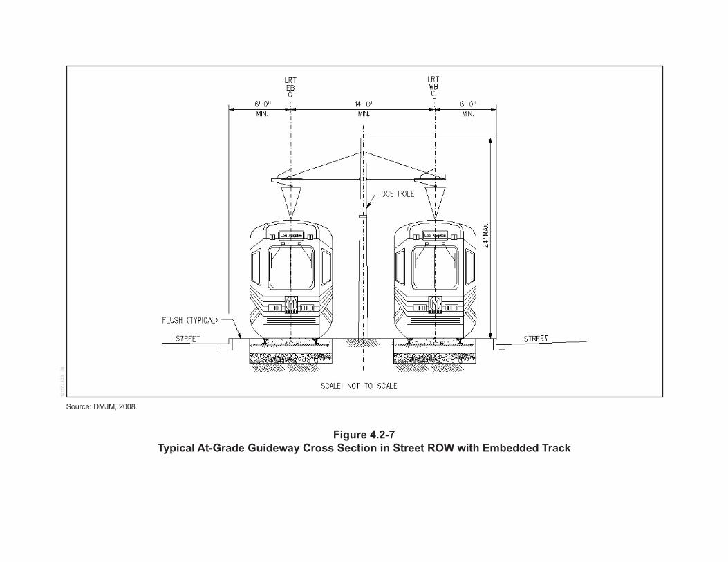
Source: DMJM, 2008.
Figure 4.2-7Typical At-Grade Guideway Cross Section in Street ROW with Embedded Track
1211
7 | J
CS
| 08
page 4-11
4. Construction Impacts
Exposition Corridor Transit Project Phase 2 DEIR January 2009
Aerial Guideway
Aerial structures would typically be constructed of concrete, but steel girders might be used for long spans or in special circumstances. The rail would be fastened directly to the top slab of a cast-in-place concrete bridge, or a separately placed slab on a steel beam bridge, or a pre-cast concrete bridge. The locations of aerial guideway construction are illustrated in Figure 4.2-1 (Segment 1—Project Facilities) to Figure 4.2-5 (Segment 3a—Project Facilities).
Construction Method
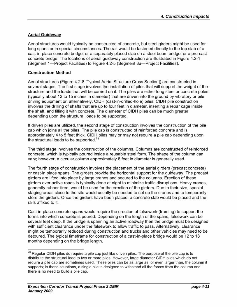
Aerial structures (Figure 4.2-8 [Typical Aerial Structure Cross Section]) are constructed in several stages. The first stage involves the installation of piles that will support the weight of the structure and the loads that will be carried on it. The piles are either long steel or concrete poles (typically about 12 to 15 inches in diameter) that are driven into the ground by vibratory or pile driving equipment or, alternatively, CIDH (cast-in-drilled-hole) piles. CIDH pile construction involves the drilling of shafts that are up to four feet in diameter, inserting a rebar cage inside the shaft, and filling it with concrete. The diameter of CIDH piles can be much greater depending upon the structural loads to be supported.
If driven piles are utilized, the second stage of construction involves the construction of the pile cap which joins all the piles. The pile cap is constructed of reinforced concrete and is approximately 4 to 5 feet thick. CIDH piles may or may not require a pile cap depending upon the structural loads to be supported.73
The third stage involves the construction of the columns. Columns are constructed of reinforced concrete, which is typically poured inside a reusable steel form. The shape of the column can vary; however, a circular column approximately 8 feet in diameter is generally used.
The fourth stage of construction involves the placement of the aerial girders (precast concrete) or cast-in place spans. The girders provide the horizontal support for the guideway. The precast girders are lifted into place by large cranes and secured to the columns. Erection of these girders over active roads is typically done at night to minimize traffic disruptions. Heavy cranes, generally rubber-tired, would be used for the erection of the girders. Due to their size, special staging areas close to the site would usually be needed to set up the cranes and to temporarily store the girders. Once the girders have been placed, a concrete slab would be placed and the rails affixed to it.
Cast-in-place concrete spans would require the erection of falsework (framing) to support the forms into which concrete is poured. Depending on the length of the spans, falsework can be several feet deep. If the bridge is spanning an active roadway then the bridge must be designed with sufficient clearance under the falsework to allow traffic to pass. Alternatively, clearance might be temporarily reduced during construction and trucks and other vehicles may need to be detoured. The typical timeframe for construction of a cast-in-place bridge would be 12 to 18 months depending on the bridge length.
73 Regular CIDH piles do require a pile cap just like driven piles. The purpose of the pile cap is to distribute the structural load to two or more piles. However, large diameter CIDH piles which do not require a pile cap are sometimes used. These piles can be as large as, or even larger than, the column it supports; in these situations, a single pile is designed to withstand all the forces from the column and there is no need to build a pile cap.
Source: DMJM, 2008.
Figure 4.2-8Typical Aerial Structure Cross Section
1211
7 | J
CS
| 08
page 4-13
4. Construction Impacts
Exposition Corridor Transit Project Phase 2 DEIR January 2009
Equipment required for aerial guideway construction would include drilling rigs, possibly specialized water jet excavators, trucks to remove excavated soil, transit mix concrete trucks and concrete pumps, specialized truck trailers to deliver pre-cast concrete beams, cranes, trucks to deliver forms, reinforcing steel, pavement saws, pre-cast concrete post tensioning jacks and related equipment, and water trucks for dust control.
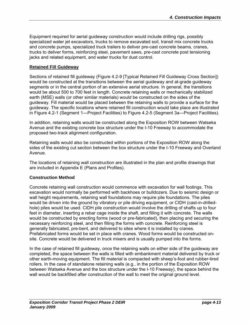
Retained Fill Guideway
Sections of retained fill guideway (Figure 4.2-9 [Typical Retained Fill Guideway Cross Section]) would be constructed at the transitions between the aerial guideway and at-grade guideway segments or in the central portion of an extensive aerial structure. In general, the transitions would be about 500 to 700 feet in length. Concrete retaining walls or mechanically stabilized earth (MSE) walls (or other similar materials) would be constructed on the sides of the guideway. Fill material would be placed between the retaining walls to provide a surface for the guideway. The specific locations where retained fill construction would take place are illustrated in Figure 4.2-1 (Segment 1—Project Facilities) to Figure 4.2-5 (Segment 3a—Project Facilities).
In addition, retaining walls would be constructed along the Exposition ROW between Watseka Avenue and the existing concrete box structure under the I-10 Freeway to accommodate the proposed two-track alignment configuration.
Retaining walls would also be constructed within portions of the Exposition ROW along the sides of the existing cut section between the box structure under the I-10 Freeway and Overland Avenue.
The locations of retaining wall construction are illustrated in the plan and profile drawings that are included in Appendix E (Plans and Profiles).
Construction Method
Concrete retaining wall construction would commence with excavation for wall footings. This excavation would normally be performed with backhoes or bulldozers. Due to seismic design or wall height requirements, retaining wall foundations may require pile foundations. The piles would be driven into the ground by vibratory or pile driving equipment, or CIDH (cast-in-drilled-hole) piles would be used. CIDH pile construction would involve the drilling of shafts up to four feet in diameter, inserting a rebar cage inside the shaft, and filling it with concrete. The walls would be constructed by erecting forms (wood or pre-fabricated), then placing and securing the necessary reinforcing steel, and then filling the forms with concrete. Reinforcing steel is generally fabricated, pre-bent, and delivered to sites where it is installed by cranes. Prefabricated forms would be set in place with cranes. Wood forms would be constructed on-site. Concrete would be delivered in truck mixers and is usually pumped into the forms.
In the case of retained fill guideway, once the retaining walls on either side of the guideway are completed, the space between the walls is filled with embankment material delivered by truck or other earth-moving equipment. The fill material is compacted with sheep’s-foot and rubber-tired rollers. In the case of standalone retaining walls (e.g., in the portion of the Exposition ROW between Watseka Avenue and the box structure under the I-10 Freeway), the space behind the wall would be backfilled after construction of the wall to meet the original ground level.
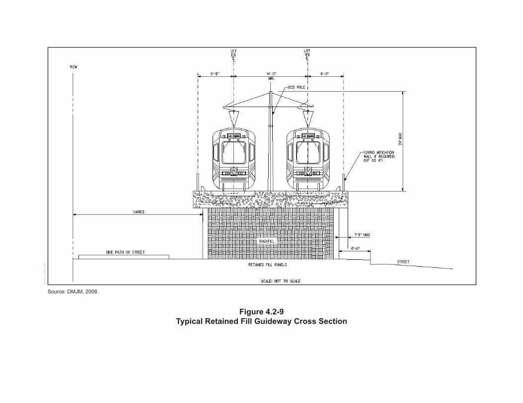
Source: DMJM, 2008.
Figure 4.2-9Typical Retained Fill Guideway Cross Section
1211
7 | J
CS
| 08
page 4-15
4. Construction Impacts
Exposition Corridor Transit Project Phase 2 DEIR January 2009
Alternative types of retaining walls such as MSE (or other similar materials) would not require forms, reinforcing steel, or concrete. With these walls, the embankment material forms a part of the structure and is constructed in conjunction with the walls.
4.2.2 Stations
At-Grade Stations
The at-grade stations would be located at or slightly above existing ground. At-grade stations would either have a center platform configuration, where one platform is located between the two tracks and serves both tracks, or a side platform configuration where two platforms are constructed in mirror image, one serving each track. A split platform station is a variation of a side platform station with two platforms staggered instead of mirrored. The platforms, per Metro Design Criteria, would be approximately 300 feet long and, depending upon projected demand, 16 feet wide to 30 feet wide in the case of center platform stations, and 12 feet wide in the case of side platform stations (refer to Appendix F [Station Plans and Maintenance Facility]).
The locations of at-grade station construction are illustrated in Figure 4.2-1 (Segment 1—Project Facilities) to Figure 4.2-5 (Segment 3a—Project Facilities).
Construction Method
Construction of the at-grade stations would involve cast-in-place concrete or pre-cast panels to construct an approximately 40 inch high platform along with ramps and stairs. Station furnishings, including canopy, railings, lighting, seating, signage and fare vending equipment, would then be installed. The stations would be constructed of standard building materials such as concrete, steel, and other materials per Metro Design Criteria. Steel-wheeled or rubber-tired compactors, graders, and small bulldozers would be required for subgrade preparation below the platform. Construction of the station would also require trucks for the removal of excavated soil; transit mix concrete trucks and concrete pumps; trucks to deliver forms, reinforcing steel, and other materials; and water trucks for dust control.
Aerial Stations
The aerial stations would be approximately 30 feet above the existing ground. Aerial stations would either have a center or side platform configuration. The platforms, per Metro Design Criteria, would be approximately 300 feet long and, depending upon projected demand, 16 feet wide to 30 feet wide in the case of center platform stations and 12 feet wide in the case of side platform stations.
The locations of aerial station construction are illustrated in Figure 4.2-1 (Segment 1—Project Facilities) to Figure 4.2-5 (Segment 3a—Project Facilities).
Construction Method
Construction of aerial stations would involve construction techniques similar to those for aerial guideways described in the “Aerial Guideway” section of Section 4.2.1 (Guideway) above. Foundations and columns would be constructed to support the platform. The station platform would typically be constructed of cast-in-place concrete with falsework. Forms would be erected, reinforcing steel would be put in place, and concrete would be placed into the forms to
page 4-16
4. Construction Impacts
Exposition Corridor Transit Project Phase 2 DEIR January 2009
construct the columns and the platform slab. Ancillary facilities would then be added including stairs, elevators, canopy, railings, lighting, seating, signage, and fare vending equipment.
Equipment required for aerial station construction would include drilling rigs, possibly specialized water jet excavators, trucks to remove excavated soil, transit mix concrete trucks and concrete pumps, specialized truck trailers to deliver pre-cast concrete beams (if used), cranes, trucks to deliver forms, reinforcing steel, pavement saws, pre-cast concrete post tensioning jacks and related equipment.
4.2.3 Systems
Traction Power Substations
Traction Power Substations (TPSSs) must be placed along the alignment at designated locations, typically at stations, per the design in order to provide the electrical power needed for the LRT vehicles. The likely locations of TPSS construction are illustrated in Figure 4.2-1 (Segment 1—Project Facilities) to Figure 4.2-5 (Segment 3a—Project Facilities), with final locations subject to refinement during Preliminary Engineering and Final Design.
Construction Method
Each TPSS site would be cleared and graded, and a concrete slab would be constructed with the appropriate underground utility connections. A grounding mat would be installed around the perimeter of the site. The TPSS is a prefabricated structure containing electrical and electronic equipment and is approximately 15 feet wide, 43 feet long, and 16 feet high. It would be delivered, mounted on the slab, and connected to the utilities. Fencing or other type of barrier would be installed around the perimeter of the site, and architectural and landscaping treatments would be applied as feasible and in accordance with Metro Design Criteria. Graders, bobcats, forklifts, cranes, and concrete and materials/equipment trucks would be required.
Overhead Contact System
The Overhead Contact System (OCS) would consist of a set of two copper/bronze wires—a contact wire and a messenger wire—supported by steel poles mounted on reinforced concrete foundations. OCS poles would be spaced along the LRT Alternatives, between or adjacent to the tracks, at a typical spacing of 150 feet.74
Construction Method
Construction of the OCS would initially involve constructing the foundations for the OCS poles. This would be accompanied by construction of duct banks and conduit for the underground electrical feeder lines from the TPSSs, followed by installation of the OCS poles. The final stage would involve installation of the TPSS feeder cables and overhead catenary lines, which would occur subsequent to guideway construction. Construction of the foundations and ducts, and installation of the poles and feeder cables, would require augers, cranes, back hoes, and concrete and materials trucks. The overhead wires would be installed from the guideway using special vehicles, such as high-rail.75 74 Assumes low-profile Overhead Catenary System. 75 A vehicle used for track or train maintenance that has the ability to operate on the rails (also spelled hi-rail).
page 4-17
4. Construction Impacts
Exposition Corridor Transit Project Phase 2 DEIR January 2009
4.2.4 Other Facilities
Maintenance Facility
A required maintenance facility is proposed to be constructed within the City of Santa Monica immediately south of the Exposition ROW, north of Exposition Boulevard, and east of Stewart Street as illustrated in Figure 4.2-3 (Segment 2—Project Facilities).
Construction Method
Development of the maintenance facility would include the construction of a Maintenance Facility shop structure that would be approximately 125,000 square feet in area and two stories in height, almost three stories in the shop areas. The structure would be constructed of concrete block, corrugated metal or similar industrial materials. Storage track and trackway to allow for movement of LRT vehicles from the mainline track to the maintenance facility area would also be installed. Other facilities on site would include a vehicle wash and a TPSS. Parking for 65 to 70 employee automobiles would also be provided.
In those areas of the site where existing structures and pavement are present, demolition would be required. Equipment typically involved in demolition includes: crawler cranes, crawler dozers/loaders, pavement breakers, rubber-tired loader/bob cats, trucks, excavator/backhoes, generator/compressors, and water trucks for dust control.
For construction of the Maintenance Facility shop structure, equipment commonly used for construction of industrial and office buildings would be required. This may involve the installation of piles to support the weight of the structure and the loads that will be carried on it. Some underground excavation would also be required for construction of the maintenance pits. Equipment would include vibratory or pile driving equipment or equipment associated with the installation of CIDH piles,76 excavators, trucks to remove excavated soil, transit mix concrete trucks and concrete pumps, cranes, trucks to deliver forms, reinforcing steel, pavement saws, pre-cast concrete post tensioning jacks and related equipment, and water trucks for dust control.
Track construction would be similar to at-grade guideway construction. Equipment would generally consist of rubber-tired excavators, steel-wheeled or rubber-tired compactors, graders, and small bulldozers. Rails and ties would be imported by truck and placed with specialized rubber-tired equipment.
Construction of a TPSS to serve the maintenance facility would be as described previously for other locations along the alignment. Graders, bobcats, forklifts, cranes, and concrete and materials/equipment trucks would be required.
Construction of the OCS to serve the maintenance facility would be as described previously along the alignment. Equipment requirements would include augers, cranes, back hoes, and concrete and materials trucks. The overhead wires would be installed using high-rail vehicles.
Construction of the vehicle wash would potentially involve erection of a prefabricated building and installation of washing equipment. Steel-wheeled or rubber-tired compactors, graders, and
76 The construction method for the installation of CIDH piles was described previously in the “Aerial Guideway” section.
page 4-18
4. Construction Impacts
Exposition Corridor Transit Project Phase 2 DEIR January 2009
small bulldozers would be required for subgrade preparation below the structure. Erection of the building would require trucks to deliver materials, and cranes.
Below grade excavation would be required for installation of the utilities and other services for the maintenance facility. Excavation equipment would potentially include excavators, front end loaders, cranes, and trucks to remove excavated soil.
Construction of the surface parking would involve subgrade preparation of the parking area, paving, and striping. Concrete curbs, lighting, driveways, sidewalks, and landscaping would be installed as necessary. Equipment used for construction would include diamond saws, pavement breakers, jackhammers, compressors, concrete pumping equipment, paving machines, dump trucks, front-end loaders, and water trucks for dust control.
Parking Facilities at Stations
Parking facilities would be constructed at eight station locations as illustrated in Figure 4.2-1 (Segment 1—Project Facilities) to Figure 4.2-5 (Segment 3a—Project Facilities).
Construction Method
Construction of the surface parking facilities would involve subgrade preparation of the parking area, paving, and striping. Concrete curbs, lighting, driveways, sidewalks, and landscaping would be installed as necessary. Equipment used for construction of surface parking facilities would include diamond saws, pavement breakers, jackhammers, compressors, concrete pumping equipment, paving machines, dump trucks, front-end loaders, and water trucks for dust control.
In the case of the proposed parking structure, equipment commonly used for building construction would be required. The first stage of construction would involve the installation of piles to support the weight of the structure and the loads that will be carried on it. This would require vibratory or pile driving equipment or the installation of CIDH piles.77 The structure would be two stories high and likely supported by a reinforced concrete frame. Equipment required would include trucks to remove excavated soil, transit mix concrete trucks and concrete pumps, cranes, trucks to deliver forms, reinforcing steel, pavement saws, pre-cast concrete post tensioning jacks and related equipment.
In those areas where existing structures and pavement are present, demolition would be required. Equipment typically involved in demolition includes: crawler cranes, crawler dozers/loaders, pavement breakers, rubber-tired loader/bob cats, trucks, excavator/backhoes, generator/compressors, and water trucks for dust control.
4.2.5 Street Widening and Reconstruction
Along portions of the LRT Alternatives, the street section would need to be widened or reconstructed to accommodate the guideway. In some locations, this would require the acquisition of properties and removal of structures and vegetation. Details on property acquisitions are described in Appendix G (Real Estate Maps) and other sections of this DEIR.
77 The construction method for the installation of CIDH piles was described previously in the “Aerial Guideway” section.
page 4-19
4. Construction Impacts
Exposition Corridor Transit Project Phase 2 DEIR January 2009
Additional street reconstruction work would be required at all at-grade crossing locations to allow for placement of the track slab and rails and modification of existing curbs, gutters, and sidewalks to accommodate the rail crossing.
The locations of street widenings and/or reconstruction are illustrated in the plan and profile drawings (Appendix E [Plans and Profiles]).
Construction Method
Where applicable, existing curbs, gutters, sidewalks, landscaping and structures would need to be demolished and utilities relocated. Equipment typically involved in demolition includes: crawler cranes, crawler dozers/loaders, pavement breakers, rubber-tired loader/bob cats, trucks, excavator/backhoes, generator/compressors, and water trucks for dust control.
Construction of new curb and gutter, sidewalks and traffic lanes would then proceed followed by the installation of lighting, signage, striping, and landscaping as necessary. Equipment used for construction would include excavators, small bulldozers, compactors, graders, transit mix concrete trucks, concrete pumping equipment, pavers, and rollers.
4.2.6 Utility Relocation & Installation
Utility relocation work would be required throughout the LRT Alternatives. The impacted utilities include storm drains, sanitary sewers, power lines, gas pipelines, electrical duct banks, oil pipelines, electrical transmission lines, lighting, irrigation pipelines, reclaimed water lines, fiber optic lines, telephone, and cable lines.
To the extent possible, the LRT Alternatives have been located to avoid conflicts with the space occupied by major utilities. Nevertheless, in certain instances, the positioning of the guideway, station and other facilities would require that conflicting utilities be relocated, modified, or protected in place. The Exposition Metro Line Construction Authority (Expo Authority) would coordinate relocations, modifications, and protection in place, with all impacted utilities under the terms of each provider’s franchise or other agreements defining the provisions for such matters.
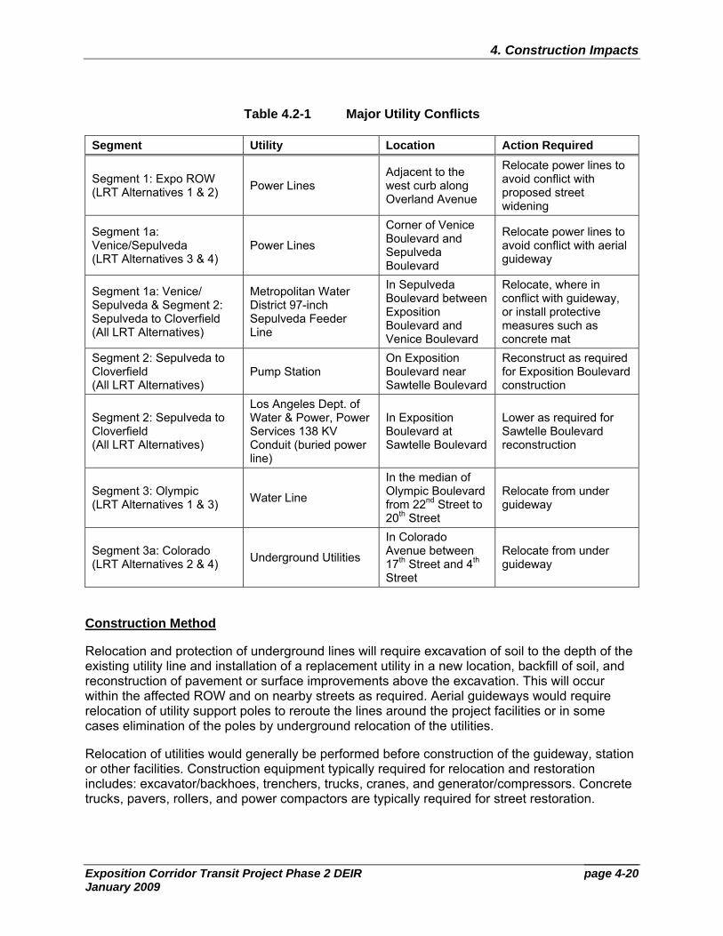
Major utility conflicts would occur at the locations listed in Table 4.2-1 (Major Utility Conflicts) pending further refinement during Preliminary Engineering and may include additional locations as the design progresses.
In addition to relocation, various new utilities will be installed as part of the LRT Alternatives including fiber optic communication lines, electrical duct banks, drainage facilities such as pipelines, catch basins, water supply lines, irrigation lines and lighting.
page 4-20
4. Construction Impacts
Exposition Corridor Transit Project Phase 2 DEIR January 2009
Table 4.2-1 Major Utility Conflicts
Segment Utility Location Action Required
Segment 1: Expo ROW (LRT Alternatives 1 & 2) Power Lines
Adjacent to the west curb along Overland Avenue
Relocate power lines to avoid conflict with proposed street widening
Segment 1a: Venice/Sepulveda (LRT Alternatives 3 & 4)
Power Lines
Corner of Venice Boulevard and Sepulveda Boulevard
Relocate power lines to avoid conflict with aerial guideway
Segment 1a: Venice/ Sepulveda & Segment 2: Sepulveda to Cloverfield (All LRT Alternatives)
Metropolitan Water District 97-inch Sepulveda Feeder Line
In Sepulveda Boulevard between Exposition Boulevard and Venice Boulevard
Relocate, where in conflict with guideway, or install protective measures such as concrete mat
Segment 2: Sepulveda to Cloverfield (All LRT Alternatives)
Pump Station On Exposition Boulevard near Sawtelle Boulevard
Reconstruct as required for Exposition Boulevard construction
Segment 2: Sepulveda to Cloverfield (All LRT Alternatives)
Los Angeles Dept. of Water & Power, Power Services 138 KV Conduit (buried power line)
In Exposition Boulevard at Sawtelle Boulevard
Lower as required for Sawtelle Boulevard reconstruction
Segment 3: Olympic (LRT Alternatives 1 & 3) Water Line
In the median of Olympic Boulevard from 22nd Street to 20th Street
Relocate from under guideway
Segment 3a: Colorado (LRT Alternatives 2 & 4) Underground Utilities
In Colorado Avenue between 17th Street and 4th Street
Relocate from under guideway
Construction Method
Relocation and protection of underground lines will require excavation of soil to the depth of the existing utility line and installation of a replacement utility in a new location, backfill of soil, and reconstruction of pavement or surface improvements above the excavation. This will occur within the affected ROW and on nearby streets as required. Aerial guideways would require relocation of utility support poles to reroute the lines around the project facilities or in some cases elimination of the poles by underground relocation of the utilities.
Relocation of utilities would generally be performed before construction of the guideway, station or other facilities. Construction equipment typically required for relocation and restoration includes: excavator/backhoes, trenchers, trucks, cranes, and generator/compressors. Concrete trucks, pavers, rollers, and power compactors are typically required for street restoration.
page 4-21
4. Construction Impacts
Exposition Corridor Transit Project Phase 2 DEIR January 2009
4.2.7 Temporary Street and Lane Closures
Street and lane closures may be necessary during construction of the project including potential closures during nights or on weekends. The extent and duration of the closures would depend on a number of factors, including the construction contract limits and individual contractors’ choices, and would be coordinated with the appropriate city jurisdiction. Restrictions on the extent and duration of the closures can be incorporated into the project construction specifications. The locations of temporary street and lane closures are discussed in Section 4.6.1 (Transportation/Traffic). In some cases, short-term full closures might be substituted for extended partial closures to reduce overall impacts.
4.2.8 Staging Areas
Construction staging areas would be located within the Exposition ROW or on land to be acquired for guideway construction, stations, the maintenance facility, parking, or TPSS construction as illustrated in Figure 4.2-1 (Segment 1—Project Facilities) to Figure 4.2-5 (Segment 3a—Project Facilities). Staging areas would be used for the storage of construction materials and equipment, location(s) of temporary offices for field personnel, parking for field personnel, and for the fabrication of construction materials (e.g., on-site welding of rail strings).
4.2.9 Haul Routes
Although there are no major retained cuts or tunnels associated with the alignment options, some material would be excavated for subgrade preparation. Some of this material may be used in the retained fill embankments depending on its suitability. Excavated material would be loaded into trucks and transported along the Exposition ROW and/or major streets to construction staging areas or to or from the nearest freeway. Some fill material may also have to be trucked to the site if sufficient material is not available or suitable for use. Actual volumes of material and specific routes would depend on a number of factors, including the construction contract limits, individual contractor’s choices, and coordination with the appropriate city jurisdictions. Restrictions on haul routes can be incorporated into the construction specifications.
The contractor would employ best management practices when transporting material to or from the study area, such as drying out the soil prior to loading the trucks, covering the soil with tarps in loaded trucks, etc. Some of the soil would be stockpiled within the project limits so that it is available to use in retained fill embankments. Excess soil will be hauled to an off-site location where it may be available for other projects requiring fill material.
Potential haul routes have been identified based on the locations of the construction with respect to major streets leading to freeway interchanges (refer to Table 4.2-2 [Potential Haul Routes and Total Number of Truck Loads]). Material would normally be hauled along the Exposition ROW, major cross streets, and the nearest freeway.

page 4-22
4. Construction Impacts
Exposition Corridor Transit Project Phase 2 DEIR January 2009
Table 4.2-2 Potential Haul Routes and Total Number of Truck Loads
Potential Haul Routes Total Number
of Truck Loads Segment 1: Expo ROW (LRT Alternatives 1 and 2) National NB to Manning WB to I-10 EB 1,077 Segment 1a: Venice/Sepulveda (LRT Alternatives 3 and 4) Venice EB to Robertson NB to I-10 WB 387 Overland NB to I-10 EB or WB 408 Venice WB to Sepulveda SB to I-405 NB 243 Sepulveda SB to I-405 NB 1,375 Sepulveda SB to National WB to I-405 SB 123 Segment 2: Sepulveda to Cloverfield (All LRT Alternatives) Pico EB to Sepulveda NB to Tennessee WB to I-405 NB 658 Bundy SB to I-10 EB 859 Centinela SB to I-10 EB or WB 1,099 Cloverfield SB to I-10 EB 264 Segment 3: Olympic (LRT Alternatives 1 and 3) 20th Street SB to I-10 WB 323 Lincoln SB to I-10 EB 535 Segment 3a: Colorado (LRT Alternatives 2 and 4) 20th Street SB to I-10 WB 264 SOURCE: DMJM Harris. NB = northbound, SB = southbound, WB = westbound, EB = eastbound
4.2.10 Construction Schedule and Staffing
The project would likely be divided into construction segments roughly corresponding to Segment 1, Segment 2, and Segment 3 or Segment 3a (as described above) in the case of the Expo ROW alignment of LRT Alternatives 1 and 2, or to Segment 1a, Segment 2, and Segment 3 or Segment 3a in the case of the Venice/Sepulveda alignment of LRT Alternatives 3 and 4.
Initial activities within any segment would include utility relocation and street widening work. This would be followed by major construction activities including guideway, station, and maintenance facility construction. Systems installation (i.e., TPSS, Overhead Catenary System/Traction Power, Communications/Train Control) and construction of the parking structure would overlap with the later phase of major construction work. Station area and right-of-way improvements (including surface parking, lighting, and landscaping) would be the final phase of construction.
page 4-23
4. Construction Impacts
Exposition Corridor Transit Project Phase 2 DEIR January 2009
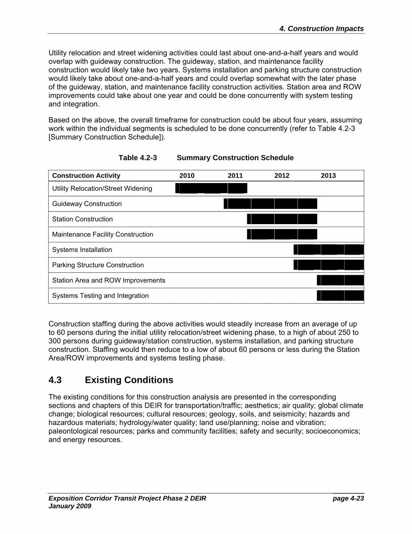
Utility relocation and street widening activities could last about one-and-a-half years and would overlap with guideway construction. The guideway, station, and maintenance facility construction would likely take two years. Systems installation and parking structure construction would likely take about one-and-a-half years and could overlap somewhat with the later phase of the guideway, station, and maintenance facility construction activities. Station area and ROW improvements could take about one year and could be done concurrently with system testing and integration.
Based on the above, the overall timeframe for construction could be about four years, assuming work within the individual segments is scheduled to be done concurrently (refer to Table 4.2-3 [Summary Construction Schedule]).
Table 4.2-3 Summary Construction Schedule
Construction Activity 2010 2011 2012 2013
Utility Relocation/Street Widening
Guideway Construction
Station Construction
Maintenance Facility Construction
Systems Installation
Parking Structure Construction
Station Area and ROW Improvements
Systems Testing and Integration
Construction staffing during the above activities would steadily increase from an average of up to 60 persons during the initial utility relocation/street widening phase, to a high of about 250 to 300 persons during guideway/station construction, systems installation, and parking structure construction. Staffing would then reduce to a low of about 60 persons or less during the Station Area/ROW improvements and systems testing phase.
4.3 Existing Conditions
The existing conditions for this construction analysis are presented in the corresponding sections and chapters of this DEIR for transportation/traffic; aesthetics; air quality; global climate change; biological resources; cultural resources; geology, soils, and seismicity; hazards and hazardous materials; hydrology/water quality; land use/planning; noise and vibration; paleontological resources; parks and community facilities; safety and security; socioeconomics; and energy resources.
page 4-24
4. Construction Impacts
Exposition Corridor Transit Project Phase 2 DEIR January 2009
4.4 Regulatory Setting
Construction activities that occur as a result of the LRT Alternatives would occur within the jurisdictions of the cities of Culver City, Los Angeles, and Santa Monica. All construction activities, including construction of the stations, road crossings, installation and realignment of utilities, installation of aerial structures, installation of tracks, and demolition activities would be subject to existing regulatory requirements, BMPs for erosion and sediment control, and applicable construction material and waste handling and management regulations. Further, construction activities would follow all applicable State building codes to ensure that structures are adequate to support the LRT Alternatives. Refer to each appropriate DEIR section for a complete discussion of applicable local, state, and federal regulations.
4.5 Analytic Methodology
By definition, construction-related impacts are temporary and would not generally cause a permanent impact. The following analysis evaluates whether or to what extent the construction scenario provided in Section 4.2 (Construction Scenario) would result in construction-related impacts.
Data used to prepare this section were taken from various sources. The analyses in this section evaluate how construction of the LRT Alternatives would impact transportation/traffic, aesthetics, air quality, global climate change, biological resources, cultural resources; geology, soils, and seismicity; hazards and hazardous materials; hydrology/water quality; land use/planning; noise and vibration; paleontological resources; parks and community facilities; safety and security; socioeconomics; and energy resources.
4.6 Criteria, Impact Evaluation, and Mitigation Measures
This section is focused on the construction of the LRT Alternatives. The construction activities that would occur under the No-Build would be completed by others, and would be evaluated for construction impacts as a part of each project’s individual environmental analysis. For example, mitigations are outlined in the I-405 Widening FEIS/EIR. No construction is proposed as a part of the TSM Alternative as additional buses would operate on existing streets.
4.6.1 Transportation/Traffic
Criterion Would construction activities interfere with or result in the closure of one or more lanes of a major traffic-carrying street for an extended period of time (one month or more)?
Segment 1: Expo ROW (LRT Alternatives 1 and 2)
Partial roadway closures of less than one month would occur on Venice Boulevard, Exposition Boulevard, Bagley Avenue, Palms/National Boulevard, Motor Avenue, Overland Avenue, Westwood Boulevard, and Military Avenue. However, it is anticipated that traffic in both directions could be maintained.
page 4-25
4. Construction Impacts
Exposition Corridor Transit Project Phase 2 DEIR January 2009
Segment 1a: Venice/Sepulveda (LRT Alternatives 3 and 4)
Construction along Segment 1a would result in the closure of one or more traffic lanes along Venice and Sepulveda Boulevards for more than one month. However, implementation of the mitigation measures listed below would serve to reduce impacts associated with closure of lanes.
Segment 2: Sepulveda to Cloverfield (All LRT Alternatives)
Partial roadway closures of less than one month would occur on Sepulveda Boulevard, Sawtelle Boulevard, Exposition Boulevard, Pico Boulevard, Barrington Avenue, Bundy Drive, Centinela Avenue, Stewart Street, 26th Street, and Cloverfield Boulevard. However, it is anticipated that traffic in both directions could be maintained.
Segment 3: Olympic (LRT Alternatives 1 and 3)
Periodic street and lane closure of less than one month would be required on Olympic Boulevard to accommodate at-grade, aerial, and retained fill guideway construction from 22nd Street to west of 11th Street. In addition, street reconstruction is proposed from 20th Street to approximately Euclid Street.
In addition to the restrictions along Olympic, partial roadway closures of less than one month may be required at the various cross streets and adjoining streets including Cloverfield, 20th, 17th, 14th, 11th, the I-10 Off-Ramp east of Lincoln Boulevard, Lincoln Boulevard, the I-10 On-Ramp west of Lincoln Boulevard, and 5th Street to allow for guideway construction. However, it is anticipated that all traffic movements could be maintained.
Segment 3a: Colorado (LRT Alternatives 2 and 4)
Construction along Segment 3a would result in the closure of one or more traffic lanes along Colorado Avenue for more than one month. However, implementation of the mitigation measures listed below would serve to reduce impacts associated with closure of lanes.
Greater detail regarding construction impacts can be found in the Transportation/Traffic Technical Background Report.
Mitigation Measures
LRT Alternatives 2, 3, and 4 could result in the closure of one or more lanes of a major traffic-carrying street for an extended period of time as identified above. However, implementation of the mitigation measures below would reduce the impacts to a less-than-significant level.
MM CON-1 To ensure that continued vehicular access to community facilities is maintained, the Expo Authority shall provide at least one lane of traffic in each direction on access cross streets that are not going to be dead-ended during construction. If one lane of traffic cannot be maintained, the Expo Authority shall provide a detour route for motorists.
MM CON-2 Before the start of construction, Worksite Traffic Control Plans (WTCP) and Traffic Circulation Plans, including identification of detour requirements, will be formulated in cooperation with the City of Los Angeles, City of Santa
page 4-26
4. Construction Impacts
Exposition Corridor Transit Project Phase 2 DEIR January 2009
Monica, Culver City and other affected jurisdictions (County, State) in accordance with the Work Area Traffic Control Handbook (WATCH) manual and Manual on Uniform Traffic Control Devices (MUTCD) as required by the relevant municipality. The WTCPs will be based on lane requirements and other special requirements defined by the Los Angeles City Department of Transportation (LADOT), the City of Santa Monica, and Culver City for construction within their city and from other appropriate agencies for construction in those jurisdictions.
MM CON-3 No designated Major or Secondary Highway will be closed to vehicular or pedestrian traffic except at night or on weekends, unless approval is granted by the jurisdiction in which it is located.
Criterion Would construction activities result in the diversion of traffic through residential areas?
In addition to the mitigation measures identified below, the Expo Authority and their construction contractor would be required to comply with each City’s guidelines and regulations. Adherence to the identified mitigation measures and the respective City’s guidelines would ensure that construction activities within residential areas would be within City expectations and that construction activities would not result in traffic diversion into nearby residential streets to the extent feasible.
Segment 1: Expo ROW (LRT Alternatives 1 and 2)
While much of the area surrounding Segment 1 includes residential uses, construction activities would generally be located within the existing Exposition ROW. Along sections of the alignment that would be constructed within city streets (such as Overland Avenue and Westwood Boulevard), through traffic lanes would be provided, thus minimizing traffic diversion. However, it cannot be reliably determined whether individual vehicles would utilize residential streets and impact residential areas.
Segment 1a: Venice/Sepulveda (LRT Alternatives 3 and 4)
Construction activities along Venice Boulevard and Sepulveda Boulevard could result in traffic delays as a result of lane closures. Along Venice Boulevard, residential areas are located north and south of the street. Construction activities would result in the loss of traffic lanes, as well as potential delays in vehicle movement. As a result, vehicle diversion could occur through the residential areas surrounding Segment 1a. The Expo Authority would avoid detouring vehicles through residential areas. However, it cannot be reliably determined whether individual vehicles would utilize residential streets and impact residential areas.
Segment 2: Sepulveda to Cloverfield (All LRT Alternatives)
While much of the construction along Segment 2 would be located within the existing Exposition ROW, construction activities could result in traffic diversions through residential areas. The residential areas with the highest potential for impacts are the neighborhoods directly south of Exposition Boulevard between Barrington Avenue and Centinela Avenue. Construction activities located at the intersection of Barrington Avenue and Exposition Boulevard, which would include at-grade guideway construction, could result in temporary traffic delays. As a result, drivers may
page 4-27
4. Construction Impacts
Exposition Corridor Transit Project Phase 2 DEIR January 2009
choose to divert through the residential neighborhood to avoid these delays. Further, construction at the intersection of Bundy Drive and Exposition Boulevard would be substantial as an aerial structure would be constructed at this location. The duration of construction is estimated to be 12 to 18 months. As a result, drivers may choose to divert through the residential areas east and west of Bundy Drive. Further, traffic diversions could occur as a result of the street reconstruction and parking construction along Exposition Boulevard, south of the alignment and directly north of residential neighborhoods. Residential streets such as Tennessee Avenue located to the south of the Exposition ROW could see an increase in traffic during construction activities.
Segment 3: Olympic (LRT Alternatives 1 and 3)
Although traffic delays could result along Olympic Boulevard as a result of construction activities, it is assumed that traffic would not be diverted through residential areas. The areas adjacent to Olympic Boulevard and to the north include Colorado Avenue, which generally consists of light-industrial and commercial uses, and to the south, consists of the I-10 Freeway. Neither Colorado Avenue nor the I-10 Freeway is considered a residential area; therefore, traffic that may divert from Olympic Boulevard during construction activities would not travel through residential areas.
Segment 3a: Colorado (LRT Alternatives 2 and 4)
Construction activities within Segment 3a would result in extensive lane closure and delays as the street would be reconfigured to allow for the LRT guideway. As a result, drivers may choose to divert through the multi-family residential area located north of Colorado Avenue. Traffic may use side streets through this area, including Broadway.
Mitigation Measures
Construction of the LRT Alternatives could result in the diversion of traffic through residential areas as described above. However, these impacts would only be temporary during the construction period and implementation of the mitigation measures below would reduce the impacts to a less-than-significant level. These measures are intended to smooth traffic flow in and around construction activity to reduce the tendency for diversions through residential areas.
MM CON-2 Listed above.
MM CON-4 The Expo Authority’s contractor will develop preferred haul route plans for the removal of excavated material. Construction will be scheduled and haul routes will be planned to minimize conflicts during school arrival and dismissal times.
MM CON-5 The Expo Authority will coordinate with other major construction projects within a 1-mile radius of the construction site to avoid, to the maximum extent practicable, overlapping haul routes with other public or private construction projects.
page 4-28
4. Construction Impacts
Exposition Corridor Transit Project Phase 2 DEIR January 2009
Criterion Would construction activities result in long-term (three months or more) loss of parking or pedestrian access that is essential for continued operation of business?
Segment 1: Expo ROW (LRT Alternatives 1 and 2)
Construction activities would result in the long-term loss of parking (that is, more than three months) in portions of Segment 1. At the eastern end of Segment 1, parking would be restricted along Exposition Boulevard to ensure that traffic lanes remain open throughout the construction phases. However, the few businesses that are located along Exposition Boulevard have surface parking lots and would not be impacted by the temporary loss of on-street parking. Further, construction activities involving the reconfiguration of Overland Avenue would result in loss of on-street parking. The majority of the nearby businesses have on-site parking, such as along Overland Avenue north of the Overland Elementary School, and therefore the loss of on-street parking is not considered essential for the continued operation of nearby businesses.
Segment 1a: Venice/Sepulveda (LRT Alternatives 3 and 4)
Construction activities along Venice and Sepulveda Boulevards would result in the long-term loss of on-street parking in order to ensure that traffic lanes remain open during construction. Construction within Segment 1a could generally occur across a five-block segment at a time. On-street parking is available along both sides of Venice Boulevard and is heavily utilized, particularly along the western portion of Venice Boulevard. On-street parking is also heavily utilized along Sepulveda Boulevard, particularly along the southern end of Sepulveda Boulevard. Further, many of the businesses located along Venice and Sepulveda Boulevards are oriented towards these major roadways and rely on pedestrian access or on-street parking for business. To ensure that on-street parking loss and pedestrian restrictions do not impact businesses for greater than three months, the mitigation measures identified below would be applied to Segment 1a, thereby ensuring that parking and pedestrian access is provided during construction.
Segment 2: Sepulveda to Cloverfield (All LRT Alternatives)
Construction activities along Segment 2 could have the potential to remove on-street parking to accommodate lane modifications during construction which could impact access. At the eastern end of Segment 2, parking could be restricted along Exposition Boulevard at the intersection of Sepulveda Boulevard. Similarly, parking in the vicinity of Exposition, Sawtelle and Pico Boulevards may be impacted during construction.
Many of the businesses adjacent to the construction activities would remain open to pedestrian access. Typically, these businesses are light industrial (i.e., automotive repair, machine shops, and the like). The mitigation measures below would reduce the impacts to an acceptable level.
Segment 3: Olympic (LRT Alternatives 1 and 3)
Construction activities along Segment 3 could have the potential to remove on-street parking to accommodate lane modifications during construction within the median which could impact access.
page 4-29
4. Construction Impacts
Exposition Corridor Transit Project Phase 2 DEIR January 2009
Many of the businesses adjacent to the construction activities would remain open to pedestrian access. Typically, these businesses are light industrial or commercial and do not rely on pedestrian traffic as a key component of their business (i.e., automotive repair, machine shops, and the like). The mitigation measures below would reduce the impacts to an acceptable level.
Segment 3a: Colorado (LRT Alternatives 2 and 4)
Under Segment 3a, the at-grade guideway and station construction would occur in the center of Colorado Avenue. As a result, on-street parking would be removed or restricted along much of Colorado Avenue between 17th Street and 2nd Street during construction activities. Further, pedestrian access to many of the Colorado facing businesses may be impacted. The duration of construction along Segment 3a is assumed to last more than three months. The mitigation measures below would reduce the impacts to an acceptable level.
Mitigation Measures
Construction of the LRT Alternatives could result in the long-term loss of parking or pedestrian access that is essential for continued operation of business. However, implementation of the mitigation measures below would reduce these impacts to a less-than-significant level.
MM CON-6 Unless otherwise specified in the worksite traffic control plan, the Expo Authority shall maintain access to the businesses that rely on on-street parking and pedestrian access during construction. If it is necessary to temporarily restrict access to a business, the Expo Authority shall provide the facility advance notice of restrictions. Unless otherwise specified in the worksite traffic control plan, the Expo Authority shall schedule access restrictions to off-peak hours or during times when the business is closed and shall not fully restrict access for the total hours of operation of a business on any given day of operation.
MM CON-7 Relative to maintaining access to businesses, construction activities shall be sequenced to minimize the temporary removal of multiple blocks of on-street parking at one time unless otherwise specified by the worksite traffic control plan.
MM CON-8 Contractors shall use temporary special signage to inform the public of closure information in advance of temporary closures. Signage shall also provide special access directions, if warranted.
4.6.2 Aesthetics
Criterion Would the project substantially degrade the existing visual character or quality of the site and its surroundings?
Segment 1: Expo ROW (LRT Alternatives 1 and 2)
This area has little formal landscaping, except for the Sara Berman Greenway located just west of Westwood Boulevard to just west of Military Avenue.
page 4-30
4. Construction Impacts
Exposition Corridor Transit Project Phase 2 DEIR January 2009
Mitigation Measures
Implementation of the mitigation measure below would reduce potential impacts resulting from construction near the Sara Berman Greenway to a less-than-significant level.
MM CON-9 To the extent possible, the Expo Authority shall protect the Sara Berman Greenway during construction of Segment 1 (Expo ROW) (LRT Alternatives 1 and 2), including the placement of a construction barrier around the perimeter of the Greenway, and notifying contractors of restrictions. Substantial damage to the Greenway caused by construction activities shall be repaired as appropriate during or after the course of construction, which could include the provision of replacement landscaping.
4.6.3 Air Quality
Criterion Would the project violate any air quality standard or contribute substantially to an existing or projected air quality violation?
Construction emissions are analyzed according to the thresholds established by the SCAQMD utilizing the URBEMIS 2007 computer model developed for ARB. Construction emissions are calculated from the activities and equipment that would be used to grade, excavate, transport soil on and off site, and prepare the study area, and to construct each of the proposed LRT Alternatives.
The construction contract for the selected alternative would require specific stipulations that the contractor must follow in order to minimize impacts during construction. A Fugitive Dust Plan would be required that would use Best Management Practices (BMPs) to control fugitive dust emissions. In addition, in conformance with the SCAQMD’s Rule 403, Fugitive Dust Plan BMPs options are available to reduce construction-related air quality impacts during construction of the LRT Alternatives.
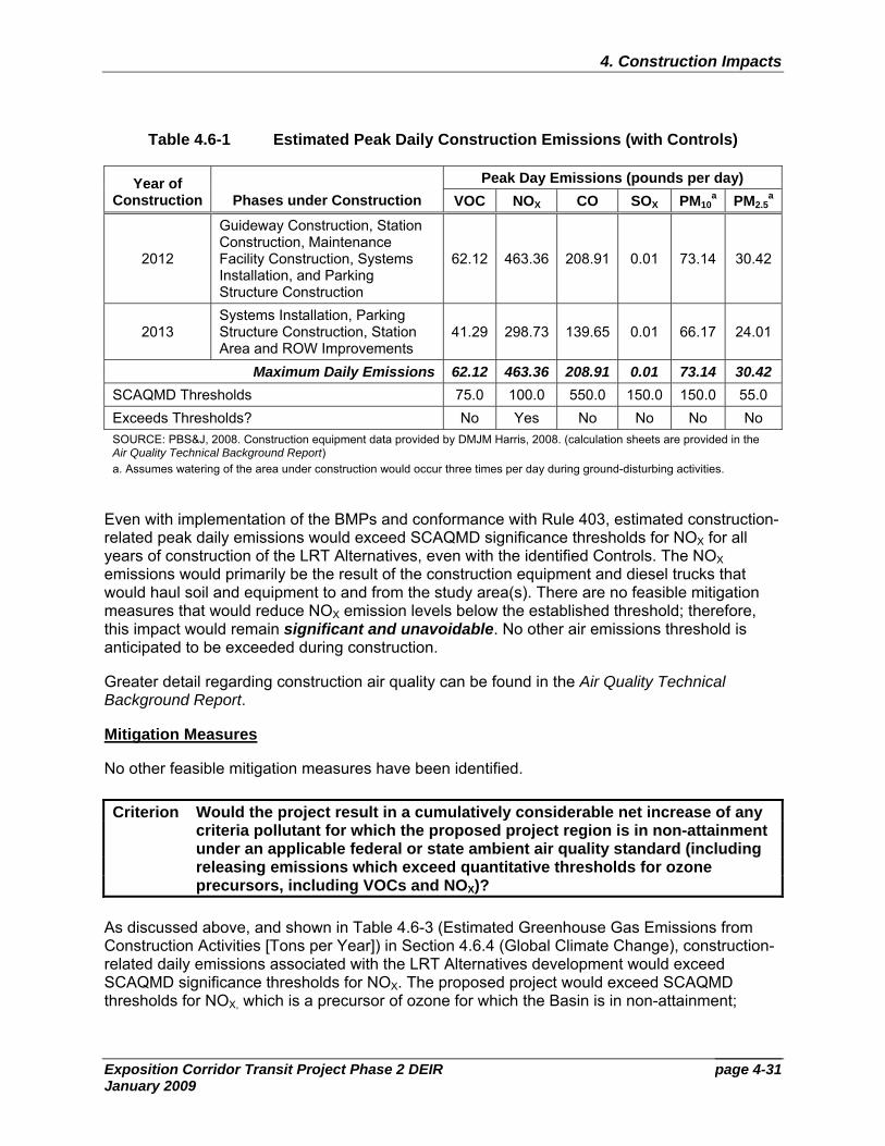
Table 4.6-1 (Estimated Peak Daily Construction Emissions [with Controls]) identifies the emission levels that would be generated during the days when the maximum amount of construction activity would be expected to occur in each year of the construction period. Compliance with SCAQMD Rule 403–Fugitive Dust and BMPs (commonly referred to as Controls), including watering of exposed surfaces three times daily has been accounted for in the peak construction estimates.
Table 4.6-1 Estimated Peak Daily Construction Emissions (with Controls)
Peak Day Emissions (pounds per day) Year of Construction Phases under Construction VOC NOX CO SOX PM10
a PM2.5a
2010 Utility Relocation 13.89 129.14 51.76 0.01 57.69 16.21
2011 Guideway Construction, Station Construction, and Maintenance Facility Construction
47.36 352.13 166.11 0.01 69.57 27.13
page 4-31
4. Construction Impacts
Exposition Corridor Transit Project Phase 2 DEIR January 2009
Table 4.6-1 Estimated Peak Daily Construction Emissions (with Controls)
Peak Day Emissions (pounds per day) Year of Construction Phases under Construction VOC NOX CO SOX PM10
a PM2.5a
2012
Guideway Construction, Station Construction, Maintenance Facility Construction, Systems Installation, and Parking Structure Construction
62.12 463.36 208.91 0.01 73.14 30.42
2013 Systems Installation, Parking Structure Construction, Station Area and ROW Improvements
41.29 298.73 139.65 0.01 66.17 24.01
Maximum Daily Emissions 62.12 463.36 208.91 0.01 73.14 30.42 SCAQMD Thresholds 75.0 100.0 550.0 150.0 150.0 55.0 Exceeds Thresholds? No Yes No No No No SOURCE: PBS&J, 2008. Construction equipment data provided by DMJM Harris, 2008. (calculation sheets are provided in the Air Quality Technical Background Report) a. Assumes watering of the area under construction would occur three times per day during ground-disturbing activities.
Even with implementation of the BMPs and conformance with Rule 403, estimated construction-related peak daily emissions would exceed SCAQMD significance thresholds for NOX for all years of construction of the LRT Alternatives, even with the identified Controls. The NOX emissions would primarily be the result of the construction equipment and diesel trucks that would haul soil and equipment to and from the study area(s). There are no feasible mitigation measures that would reduce NOX emission levels below the established threshold; therefore, this impact would remain significant and unavoidable. No other air emissions threshold is anticipated to be exceeded during construction.
Greater detail regarding construction air quality can be found in the Air Quality Technical Background Report.
Mitigation Measures
No other feasible mitigation measures have been identified.
Criterion Would the project result in a cumulatively considerable net increase of any criteria pollutant for which the proposed project region is in non-attainment under an applicable federal or state ambient air quality standard (including releasing emissions which exceed quantitative thresholds for ozone precursors, including VOCs and NOX)?
As discussed above, and shown in Table 4.6-3 (Estimated Greenhouse Gas Emissions from Construction Activities [Tons per Year]) in Section 4.6.4 (Global Climate Change), construction-related daily emissions associated with the LRT Alternatives development would exceed SCAQMD significance thresholds for NOX. The proposed project would exceed SCAQMD thresholds for NOX, which is a precursor of ozone for which the Basin is in non-attainment;
page 4-32
4. Construction Impacts
Exposition Corridor Transit Project Phase 2 DEIR January 2009
therefore, the proposed project would result in a cumulatively considerable contribution of NOX during construction of the proposed project. SCAQMD Rule 403 and BMPs would be implemented during construction activities; however, no other feasible mitigation measures have been identified to reduce NOX emissions to a level below SCAQMD threshold for the LRT Alternatives. Therefore, impacts would be significant, and the cumulative contribution would be considered significant and unavoidable.
Mitigation Measures
No other feasible mitigation measures have been identified.
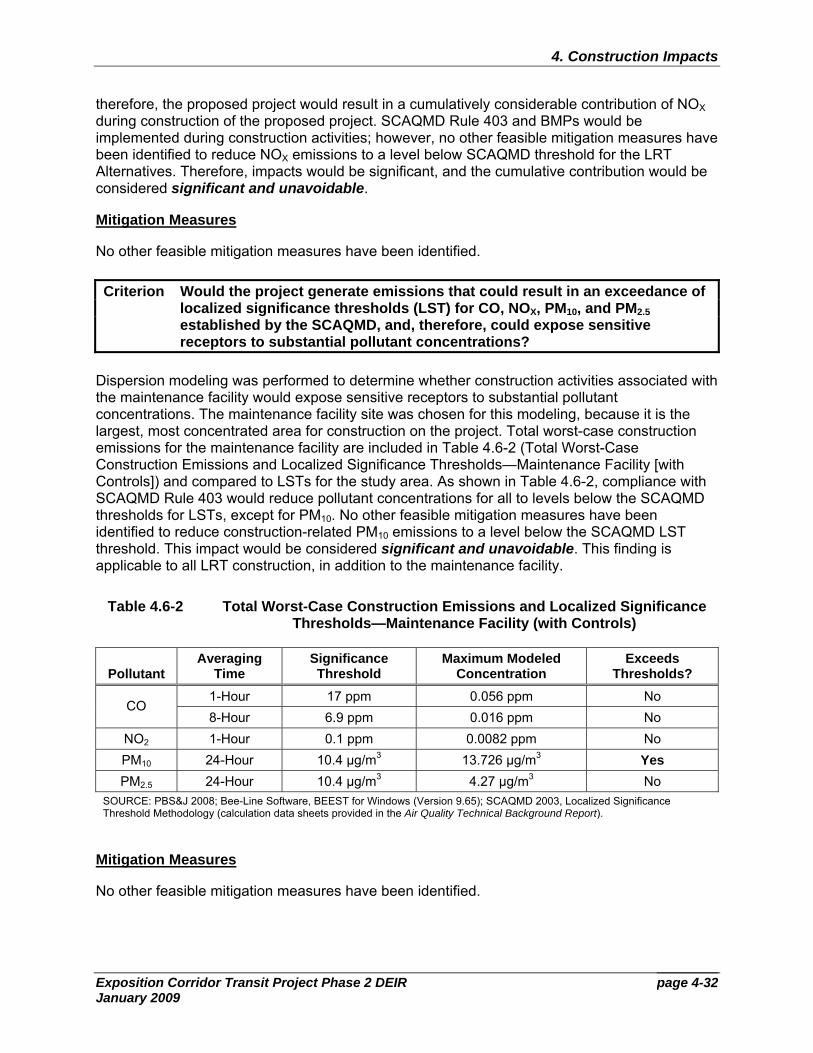
Criterion Would the project generate emissions that could result in an exceedance of localized significance thresholds (LST) for CO, NOX, PM10, and PM2.5 established by the SCAQMD, and, therefore, could expose sensitive receptors to substantial pollutant concentrations?
Dispersion modeling was performed to determine whether construction activities associated with the maintenance facility would expose sensitive receptors to substantial pollutant concentrations. The maintenance facility site was chosen for this modeling, because it is the largest, most concentrated area for construction on the project. Total worst-case construction emissions for the maintenance facility are included in Table 4.6-2 (Total Worst-Case Construction Emissions and Localized Significance Thresholds—Maintenance Facility [with Controls]) and compared to LSTs for the study area. As shown in Table 4.6-2, compliance with SCAQMD Rule 403 would reduce pollutant concentrations for all to levels below the SCAQMD thresholds for LSTs, except for PM10. No other feasible mitigation measures have been identified to reduce construction-related PM10 emissions to a level below the SCAQMD LST threshold. This impact would be considered significant and unavoidable. This finding is applicable to all LRT construction, in addition to the maintenance facility.
Table 4.6-2 Total Worst-Case Construction Emissions and Localized Significance Thresholds—Maintenance Facility (with Controls)
Pollutant Averaging
Time Significance Threshold
Maximum Modeled Concentration
Exceeds Thresholds?
1-Hour 17 ppm 0.056 ppm No CO
8-Hour 6.9 ppm 0.016 ppm No NO2 1-Hour 0.1 ppm 0.0082 ppm No PM10 24-Hour 10.4 µg/m3 13.726 µg/m3 Yes PM2.5 24-Hour 10.4 µg/m3 4.27 µg/m3 No
SOURCE: PBS&J 2008; Bee-Line Software, BEEST for Windows (Version 9.65); SCAQMD 2003, Localized Significance Threshold Methodology (calculation data sheets provided in the Air Quality Technical Background Report).
Mitigation Measures
No other feasible mitigation measures have been identified.
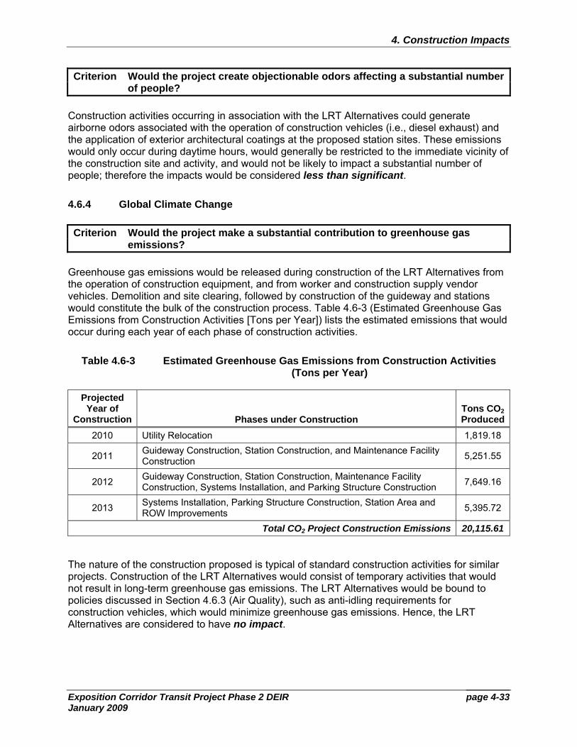
page 4-33
4. Construction Impacts
Exposition Corridor Transit Project Phase 2 DEIR January 2009
Criterion Would the project create objectionable odors affecting a substantial number of people?
Construction activities occurring in association with the LRT Alternatives could generate airborne odors associated with the operation of construction vehicles (i.e., diesel exhaust) and the application of exterior architectural coatings at the proposed station sites. These emissions would only occur during daytime hours, would generally be restricted to the immediate vicinity of the construction site and activity, and would not be likely to impact a substantial number of people; therefore the impacts would be considered less than significant.
4.6.4 Global Climate Change
Criterion Would the project make a substantial contribution to greenhouse gas emissions?
Greenhouse gas emissions would be released during construction of the LRT Alternatives from the operation of construction equipment, and from worker and construction supply vendor vehicles. Demolition and site clearing, followed by construction of the guideway and stations would constitute the bulk of the construction process. Table 4.6-3 (Estimated Greenhouse Gas Emissions from Construction Activities [Tons per Year]) lists the estimated emissions that would occur during each year of each phase of construction activities.
Table 4.6-3 Estimated Greenhouse Gas Emissions from Construction Activities (Tons per Year)
Projected Year of
Construction Phases under Construction Tons CO2Produced
2010 Utility Relocation 1,819.18
2011 Guideway Construction, Station Construction, and Maintenance Facility Construction 5,251.55
2012 Guideway Construction, Station Construction, Maintenance Facility Construction, Systems Installation, and Parking Structure Construction 7,649.16
2013 Systems Installation, Parking Structure Construction, Station Area and ROW Improvements 5,395.72
Total CO2 Project Construction Emissions 20,115.61
The nature of the construction proposed is typical of standard construction activities for similar projects. Construction of the LRT Alternatives would consist of temporary activities that would not result in long-term greenhouse gas emissions. The LRT Alternatives would be bound to policies discussed in Section 4.6.3 (Air Quality), such as anti-idling requirements for construction vehicles, which would minimize greenhouse gas emissions. Hence, the LRT Alternatives are considered to have no impact.
page 4-34
4. Construction Impacts
Exposition Corridor Transit Project Phase 2 DEIR January 2009
4.6.5 Biological Resources
Criterion Would the project impact any MBTA protected species and/or avian species protected under Section 3503 of the Fish and Game Code?
Bird nests were observed within the trees in the residential areas adjacent to Segment 1 during the December 19, 2007, biological field survey. It could not be determined at the time of the field survey which species occupied these nests. In addition, the study area also presents many nesting opportunities for birds. Areas with suitable nesting habitat include the trees lining the alignments, along proposed street widenings, and trees within the property of the proposed maintenance facility.
The removal of an active nest of a MBTA and/or Fish and Game Code protected species would be a violation of the MBTA and/or Fish and Game Code. The magnitude of the impact would depend on the species affected.
Given the discussion above, implementation of the proposed project could impact MBTA protected species and/or avian species protected under Section 3503 of the Fish and Game Code; however, implementation of the mitigation measure below would reduce impacts to a less-than-significant level.
Mitigation Measures
MM CON-10 During construction of the proposed project, the removal of trees, shrubs, or weedy vegetation should be avoided during the February 1 through August 31 bird nesting period. If the removal of trees, shrubs, or weedy vegetation were to occur during the nesting period, a survey for nesting birds shall be conducted by a qualified wildlife biologist no earlier than 14 days prior to the removal of trees, shrubs, grassland vegetation, buildings, or other construction activities. Survey results shall be valid for 21 days following the survey. The area surveyed should include all construction areas with the potential to support nesting birds protected by the MBTA and/or Section 3503 of the Fish and Game Code, as well as areas within 75 feet of the boundaries, as practicable or as determined by the biologist in the field, of the areas to be cleared or as otherwise determined by the biologist. If no vegetation or tree removal is proposed during the nesting period, no surveys would be required.
In the event that an active nest is discovered in the areas to be cleared, or in other habitats within 75 feet of construction boundaries, clearing and construction should be postponed within this area for at least two weeks or until a wildlife biologist has determined that the young have fledged (left the nest), the nest is vacated, and there is no evidence of second nesting attempts. Other buffers or construction requirements may be determined by the wildlife biologist in the field as practicable.
page 4-35
4. Construction Impacts
Exposition Corridor Transit Project Phase 2 DEIR January 2009
4.6.6 Cultural Resources
Criterion Would the project result in significant impacts under CEQA to previously unidentified archaeological resources?
Work proposed in connection with the LRT Alternatives involves ground-disturbing activities that may potentially affect unidentified archaeological resources. While these effects are the result of construction, their outcome would be long term. Therefore, the mitigation measures are included in Section 3.7 (Cultural Resources).
4.6.7 Geology, Soils, and Seismicity
Criterion Would the project result in substantial soil erosion or the loss of topsoil?
The project would include ground-disturbing activities, such as excavation and trenching for foundations and utilities (associated with the transit stations, aerial structures, and maintenance facility) and soil compaction and site grading associated with the implementation of a new track system, all of which would temporarily disturb soils.
The State Water Resources Control Board—through its National Pollutant Discharge Elimination System (NPDES) Program—requires erosion and sediment controls for construction projects with more than 1 acre of land disturbance. Requirements associated with the NPDES Program include preparation and implementation of a Storm Water Pollution Prevention Plan (SWPPP) and a Water Quality Management Plan (WQMP), with construction-period and permanent erosion and sediment controls; preparation and implementation of an erosion and sediment control plan, describing both construction-period and permanent erosion and sediment controls; and construction site inspection. The project would be required to comply with these existing regulations. Adherence to these requirements would prevent substantial on-site erosion and would ensure that the LRT Alternatives would not result in substantial soil erosion or the loss of topsoil; hence the impacts would be considered less than significant.
4.6.8 Hazards and Hazardous Materials
Criterion Would the project create the potential for upset or accident conditions involving the release of hazardous materials?
This analysis focuses on any release of hazardous materials that could occur during construction-related activities, including track removal, grading, and/or demolition.
With regard to contaminated soils, portions of the proposed project follow the existing Exposition ROW, which has remnants of the old railroad tracks and associated soils that may be contaminated. Historically, lead arsenates were used as a means of weed control along the ROW by railroad companies. Lead arsenates can leave high levels of lead and arsenic in the soil. Exposure during soil disturbance may pose a human health risk. These contaminants were encountered during the construction of Expo Phase 1, and it is likely that lead and arsenic contaminants are present in the Expo Phase 2 ROW (LACMTA 2005).
page 4-36
4. Construction Impacts
Exposition Corridor Transit Project Phase 2 DEIR January 2009
Some areas along the LRT Alternatives could also be contaminated from the unauthorized release of other hazardous substances into the soil. In addition, construction activities would also occur on or near documented hazardous materials sites that were previously listed in Table 3.9-2 (Type and Number of Environmental Cases and Spill Sites by Segment) in Section 3.9.2 (Existing Conditions), and on or near permitted facilities listed in Table 3.9-1 (Type and Number of Permitted Facilities using Hazardous Materials by Segment) in Section 3.9.2.
With regard to building materials, demolition activities would require the removal of temporary or permanent structures for the LRT Alternatives. If buildings proposed for demolition have been constructed prior to 1970 these buildings could contain asbestos and/or lead-based paints, and their demolition might require abatement prior to construction activities. With demolition activities, construction workers and nearby workers and/or residents will be protected from potential exposure to airborne lead-based paint dust, asbestos fibers, and/or other contaminants by preparing and implementing a Site Health and Safety Plan that meets OSHA requirements prior to commencement of work in any contaminated area.
Mitigation Measures
As noted above, the project could create the potential for upset or accident conditions during construction activities that could release hazardous materials; however, compliance with federal, state, and local laws and regulations governing hazardous materials use, disposal, and emergency response in addition to the mitigation measures below would reduce potential health risks to a less-than-significant level.
The mitigation measure would ensure that hazardous, or potentially hazardous, materials would be properly handled during construction activities.
MM CON-11 Prior to any ground disturbance or demolition, the Expo Authority shall:
• Prepare a preliminary environmental site assessment (ESA) for the preferred LRT Alternative, which shall be submitted for review to the appropriate regulatory agency(s). The ESA shall evaluate, at a minimum, the potential for soil and groundwater contamination, as well as the potential for exposure to mold, lead, and asbestos.
• If contaminated areas are identified within the construction area, the Expo Authority shall coordinate with the appropriate regulatory agencies to determine the need for further investigation and/or remediation of the contaminated site.
The mitigation measure below would ensure that the potential risk of contamination by unknown contaminants would be minimized by requiring investigation and remediation if encountered during construction.
MM CON-12 In the event that previously unknown or unidentified soil and/or groundwater contamination that could present a threat to human health or the environment during construction of the proposed project is encountered, construction activities in the immediate vicinity of the contamination shall cease immediately. If contamination is encountered, measures shall be prepared and implemented that (1) identifies the contaminants of concern and (2) describes measures to be taken to protect workers, and the public from
page 4-37
4. Construction Impacts
Exposition Corridor Transit Project Phase 2 DEIR January 2009
exposure to potential site hazards. Such measures would include a range of options, including, but not limited to, physical site controls during construction, remediation, long-term monitoring, post-development maintenance or access limitations, or some combination thereof. Depending on the nature of contamination, if any, appropriate agencies shall be notified (e.g., City Fire Department). A Site Health and Safety Plan that meets Cal-OSHA requirements shall be prepared and in place prior to commencement of work in any contaminated area.
Criterion Would the project physically interfere with an adopted emergency response or evacuation plan?
Emergency response and emergency evacuation plans can be impacted by temporary or permanent circulation changes, including road closures, lane reconfigurations, and other access changes associated with construction activities,
Section 4.6.1 (Transportation/Traffic) addresses the circulation changes proposed as part of the project construction and those mitigations that have been identified to avoid or reduce potential project-related congestion. Section 4.6.14 (Safety and Security) addresses interference with local circulation and emergency response times during construction activities. The conclusions identified demonstrate that the proposed project would not interfere with any adopted emergency access and evacuation plans; hence, the impact would be less than significant, as noted in each of those sections.
4.6.9 Hydrology/Water Quality
Criterion Would the proposed project conflict with applicable legal requirements related to hydrology or water quality, including a violation of state water quality standards or waste discharge requirements?
The applicable waste discharge requirements (WDRs) for the Expo Phase 2 project are specified in the Municipal NPDES Permit, the Construction General Permit, the Industrial General Permit, and possibly, the Discharge of Non-Hazardous Contaminated Soils WDRs and the Construction Dewatering WDRs.
While each of the LRT Alternatives would result in different construction scenarios associated with grading activities, an increase in impervious areas, the placement of additional fill, and/or building demolition, the regulatory mechanisms that are required to address construction-related water quality impacts associated with each of these activities would apply to each LRT Alternative; hence, the impacts would be less than significant.
Criterion Would the proposed project substantially degrade groundwater quality or interfere with groundwater recharge, or deplete groundwater resources in a manner that would cause water-related hazards such as subsidence?
During construction of any of the LRT Alternatives, temporary dewatering may be required if groundwater is encountered or construction occurs during the wet-weather season and
page 4-38
4. Construction Impacts
Exposition Corridor Transit Project Phase 2 DEIR January 2009
dewatering of excavations is required. The depth to groundwater is estimated to be between 30 and 50 feet below ground surface (bgs). Groundwater is not expected to be a constraint since the proposed alignments are to be constructed almost entirely at grade or above grade with cuts less than 6 feet in depth. Therefore, the potential for construction pollutants from spills and leaks to migrate to groundwater is minimal. However, perched (local shallow groundwater) may be encountered. Construction activities would require coverage under the Construction General Permit and preparation of a SWPPP, including spill prevention and control BMPs, waste and materials management BMPs, and other BMPs designed to protect both surface and groundwater quality. Municipal Codes require compliance with these General Permits ensuring that General Permit provisions are met. Further, if unanticipated groundwater is encountered, it would be subject to the Construction Dewatering General Permit described in Section 3.10.3 (Regulatory Setting); hence the impacts would be less than significant.
4.6.10 Land Use/Planning
Criterion Would the project result in the physical division of an established community?
During project construction, access to land uses would be periodically impacted. Lane restrictions (e.g., no left turns, right in/right out only) would be required along adjacent roads and intersections during construction. If these restrictions were to result in permanent behavioral shifts with regards to access to businesses or community services, this would be considered an impact. However, the mitigation measure identified below would ensure that at least one lane of traffic is provided in each direction or a detour route is provided during any restrictions in order to ensure access is maintained to adjacent properties. Therefore, the impacts would be considered less than significant.
Mitigation Measures
MM CON-6 Listed above.
4.6.11 Noise and Vibration
Criterion Would the project expose the public to, or generate, noise levels in excess of the Federal Transit Administration (FTA) noise impact criteria?
Construction noise levels depend on the number of pieces and type of equipment, their general condition, the amount of time each piece operates per day, the presence or lack of noise attenuating features such as walls and berms, and the location of the construction activities relative to the sensitive receptors. The majority of these variables are left to the discretion of the contractor so that assessment of construction noise is a professional judgment of the likely means and methods that would be used by the contractor.
The construction of LRT guideway requires use of heavy earth-moving equipment, pneumatic tools, generators, concrete pumps, and similar equipment. Greater detail regarding construction noise analysis can be found in the Noise and Vibration Technical Background Report.
page 4-39
4. Construction Impacts
Exposition Corridor Transit Project Phase 2 DEIR January 2009
Without noise mitigation, construction of the project is expected to generate noise levels that exceed the limits in the Metro Design Criteria. Mitigation measures would reduce noise levels below the limits of the Metro Design Criteria and the city construction noise thresholds; hence the impacts would be considered less than significant for all LRT Alternatives.
Mitigation Measures
Compliance with existing regulations and implementation of mitigation measures would reduce temporary noise impacts during construction to a less-than-significant level.
MM CON-13 The Expo Authority’s contractor shall develop a Noise Control Plan demonstrating how he will achieve the more restrictive of the Metro Design Criteria noise limits and the noise limits of the city noise control ordinance. The plan shall include measurements of existing noise, a list of the major pieces of construction equipment that will be used, and predictions of the noise levels at the closest noise-sensitive receptors (residences, hotels, schools, churches, temples, and similar facilities). The Noise Control Plan will need to be approved by the Expo Authority prior to initiating construction.
Where the construction cannot be preformed in accordance with the requirements of the Metro or applicable city noise limits, the contractor shall investigate alternative construction measures that would result in lower sound levels. The contractor shall conduct noise monitoring to demonstrate compliance with contract noise limits.
MM CON-14 The contractor shall utilize a combination of the following options of best management practices for noise abatement to comply with the Metro Design Criteria:
• The contractor shall utilize specialty equipment equipped with enclosed engines and/or high-performance mufflers as commercially available.
• The contractor shall locate equipment and staging areas as far from noise-sensitive receptors as possible.
• The contractor shall limit unnecessary idling of equipment.
• The contractor shall install temporary noise barriers as determined by the Noise Control Plan.
• The contractor shall reroute construction-related truck traffic away from residential streets to the extent permitted by the relevant municipality.
• The contractor shall avoid impact pile driving where possible. Where geological conditions permit their use, drilled piles or a vibratory pile driver is generally quieter.
page 4-40
4. Construction Impacts
Exposition Corridor Transit Project Phase 2 DEIR January 2009
Criterion Would the project expose the public to, or generate, excessive groundborne vibration, groundborne noise levels, or vibration levels in buildings exceeding the FTA vibration impact criteria?
Some activities, such as pile driving, pavement breaking, and the use of tracked vehicles (e.g., bulldozers), could result in perceptible levels of groundborne vibration. However, these activities would be limited in duration and vibration levels are likely to be well below thresholds for minor cosmetic building damage.
Given that planned construction would consist of only a limited number of activities with potential to generate vibration, no special mitigation measures are required to avoid vibration impact during construction; hence the impacts would be considered less than significant for all LRT Alternatives. Greater detail regarding construction vibration can be found in the Noise and Vibration Technical Background Report.
4.6.12 Paleontological Resources
Criterion Would the project directly or indirectly destroy or disturb a unique paleontological resource or site or unique geologic feature?
Work proposed in connection with the LRT Alternatives involves ground-disturbing activities that may potentially affect paleontological resources. While these effects are the result of construction, their outcome would be long-term. Therefore, the mitigation measures are included in Section 3.13 (Paleontological Resources).
4.6.13 Parks and Community Facilities
Criterion Would the proposed project disrupt community facilities and services through a reduction in access to community facilities or cause a substantial alteration of service areas?
Construction of the project would result in the temporary loss of access and parking when the community facility abuts the proposed segment (Table 4.6-4 [Access, Parking, and Service Area Impacts on Community Facilities]). However, construction in any one area would be of limited duration as demolition, grading, and construction would be phased and therefore occur in a progression. While it may be necessary to temporarily restrict access to, or parking for, community facilities during construction, these restrictions would be temporary and would cease upon completion of construction.
Greater detail on parks and community facilities can be found in the Parks and Community Facilities Technical Background Report.
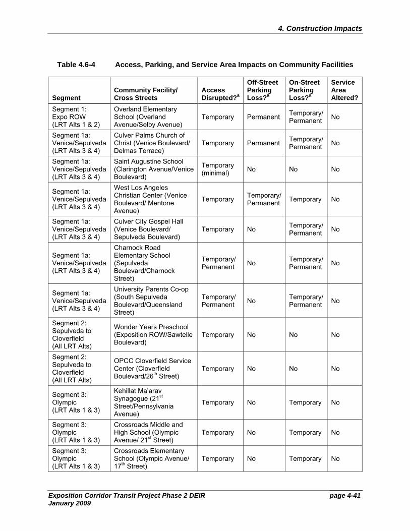
page 4-41
4. Construction Impacts
Exposition Corridor Transit Project Phase 2 DEIR January 2009
Table 4.6-4 Access, Parking, and Service Area Impacts on Community Facilities
Segment Community Facility/ Cross Streets
Access Disrupted?a
Off-Street Parking Loss?a
On-Street Parking Loss?a
Service Area Altered?
Segment 1: Expo ROW (LRT Alts 1 & 2)
Overland Elementary School (Overland Avenue/Selby Avenue)
Temporary Permanent Temporary/ Permanent No
Segment 1a: Venice/Sepulveda (LRT Alts 3 & 4)
Culver Palms Church of Christ (Venice Boulevard/ Delmas Terrace)
Temporary Permanent Temporary/ Permanent No
Segment 1a: Venice/Sepulveda (LRT Alts 3 & 4)
Saint Augustine School (Clarington Avenue/Venice Boulevard)
Temporary (minimal) No No No
Segment 1a: Venice/Sepulveda (LRT Alts 3 & 4)
West Los Angeles Christian Center (Venice Boulevard/ Mentone Avenue)
Temporary Temporary/Permanent Temporary No
Segment 1a: Venice/Sepulveda (LRT Alts 3 & 4)
Culver City Gospel Hall (Venice Boulevard/ Sepulveda Boulevard)
Temporary No Temporary/ Permanent No
Segment 1a: Venice/Sepulveda (LRT Alts 3 & 4)
Charnock Road Elementary School (Sepulveda Boulevard/Charnock Street)
Temporary/ Permanent No Temporary/
Permanent No
Segment 1a: Venice/Sepulveda (LRT Alts 3 & 4)
University Parents Co-op (South Sepulveda Boulevard/Queensland Street)
Temporary/ Permanent No Temporary/
Permanent No
Segment 2: Sepulveda to Cloverfield (All LRT Alts)
Wonder Years Preschool (Exposition ROW/Sawtelle Boulevard)
Temporary No No No
Segment 2: Sepulveda to Cloverfield (All LRT Alts)
OPCC Cloverfield Service Center (Cloverfield Boulevard/26th Street)
Temporary No No No
Segment 3: Olympic (LRT Alts 1 & 3)
Kehillat Ma’arav Synagogue (21st Street/Pennsylvania Avenue)
Temporary No Temporary No
Segment 3: Olympic (LRT Alts 1 & 3)
Crossroads Middle and High School (Olympic Avenue/ 21st Street)
Temporary No Temporary No
Segment 3: Olympic (LRT Alts 1 & 3)
Crossroads Elementary School (Olympic Avenue/ 17th Street)
Temporary No Temporary No
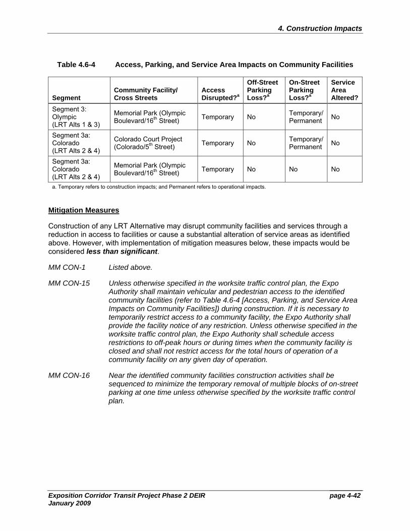
page 4-42
4. Construction Impacts
Exposition Corridor Transit Project Phase 2 DEIR January 2009
Table 4.6-4 Access, Parking, and Service Area Impacts on Community Facilities
Segment Community Facility/ Cross Streets
Access Disrupted?a
Off-Street Parking Loss?a
On-Street Parking Loss?a
Service Area Altered?
Segment 3: Olympic (LRT Alts 1 & 3)
Memorial Park (Olympic Boulevard/16th Street) Temporary No Temporary/
Permanent No
Segment 3a: Colorado (LRT Alts 2 & 4)
Colorado Court Project (Colorado/5th Street) Temporary No Temporary/
Permanent No
Segment 3a: Colorado (LRT Alts 2 & 4)
Memorial Park (Olympic Boulevard/16th Street) Temporary No No No
a. Temporary refers to construction impacts; and Permanent refers to operational impacts.
Mitigation Measures
Construction of any LRT Alternative may disrupt community facilities and services through a reduction in access to facilities or cause a substantial alteration of service areas as identified above. However, with implementation of mitigation measures below, these impacts would be considered less than significant.
MM CON-1 Listed above.
MM CON-15 Unless otherwise specified in the worksite traffic control plan, the Expo Authority shall maintain vehicular and pedestrian access to the identified community facilities (refer to Table 4.6-4 [Access, Parking, and Service Area Impacts on Community Facilities]) during construction. If it is necessary to temporarily restrict access to a community facility, the Expo Authority shall provide the facility notice of any restriction. Unless otherwise specified in the worksite traffic control plan, the Expo Authority shall schedule access restrictions to off-peak hours or during times when the community facility is closed and shall not restrict access for the total hours of operation of a community facility on any given day of operation.
MM CON-16 Near the identified community facilities construction activities shall be sequenced to minimize the temporary removal of multiple blocks of on-street parking at one time unless otherwise specified by the worksite traffic control plan.
page 4-43
4. Construction Impacts
Exposition Corridor Transit Project Phase 2 DEIR January 2009
4.6.14 Safety and Security
Criterion Would the project substantially limit the delivery of community safety services, such as police, fire, or emergency services?
The analysis in this section focuses on the safety and security impacts to passengers, pedestrians, and motorists resulting from the construction of the project. Impacts could result from decreased police and fire response times due to the construction of the proposed project for any of the LRT Alternatives.
Mitigation Measures
Construction of any of the LRT Alternatives could substantially limit the delivery of community safety services, such as police, fire, or emergency services, to locations along the proposed alignments. However, compliance with the identified mitigation measures below would reduce impacts to a less-than-significant level.
MM CON-17 The Expo Authority shall maintain access to all police and fire stations at all times during construction.
MM CON-18 During construction of the LRT Alternatives, the Expo Authority shall coordinate with the cities of Culver City, Santa Monica, and Los Angeles and inform the appropriate community safety provider of the construction emergency response procedures as incorporated into the Contractor’s Systems Safety Program Plan. The Plan will include a detailed description of all emergency response procedures that shall be implemented by the contractor, so as to provide other public safety providers with the knowledge of the contractor’s response plan in order to provide a fast, controlled, and coordinated response to the various types of emergencies. Additionally, the Expo Authority shall encourage the cities of Culver City, Santa Monica, and Los Angeles to update their emergency response procedures to address construction of the LRT Alternatives.
4.6.15 Socioeconomics
Criterion Would construction activities disrupt a business for a period of three months or more?
As previously shown in Table 4.2-3 (Summary Construction Schedule), construction associated with the LRT Alternatives could last up to four years. Therefore, businesses located in close proximity to or along the streets intended for construction could be disrupted as a result of noise, air quality, access, traffic, aesthetics, and a number of other construction-related issues identified throughout this section.
Mitigation Measures
Potential impacts to businesses have been addressed elsewhere in this section. As an example, noise resulting from construction of the LRT Alternatives would be reduced through the implementation of MM CON-13 and MM CON-14 from Section 4.6.11 (Noise and Vibration).
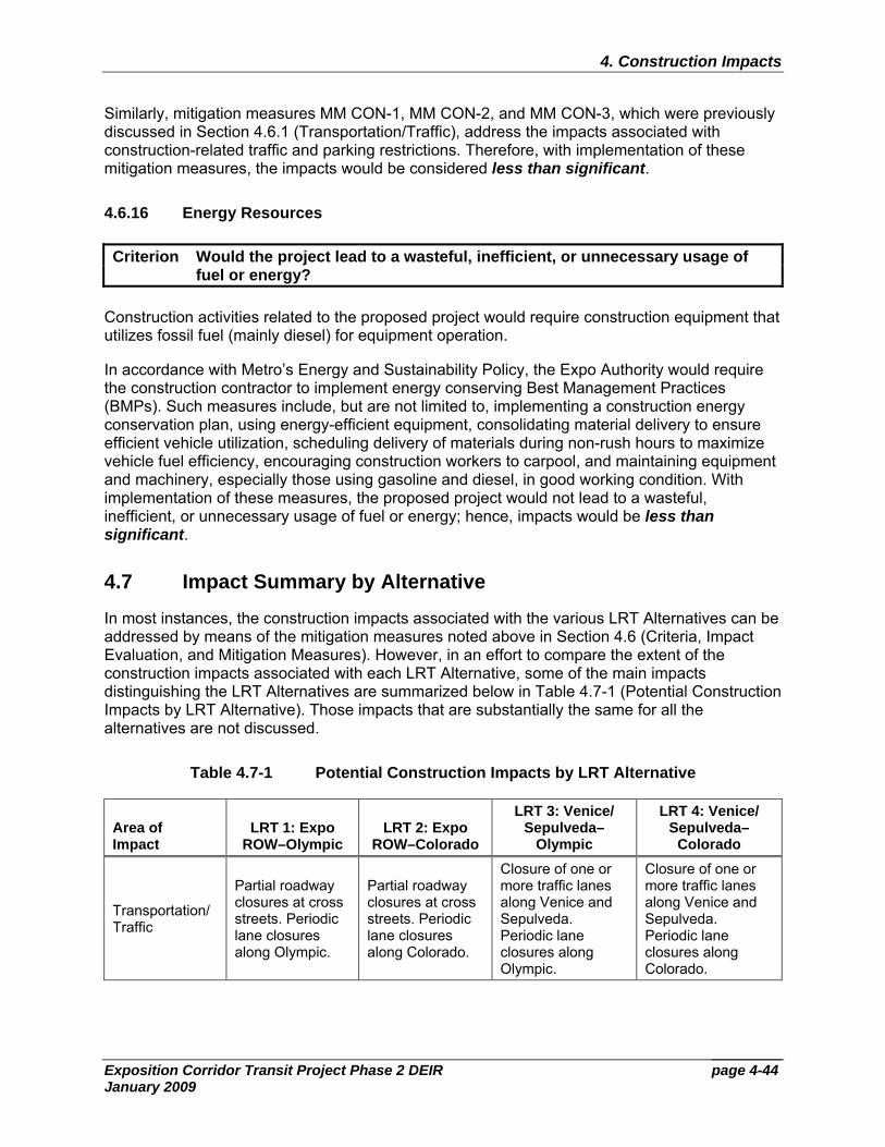
page 4-44
4. Construction Impacts
Exposition Corridor Transit Project Phase 2 DEIR January 2009
Similarly, mitigation measures MM CON-1, MM CON-2, and MM CON-3, which were previously discussed in Section 4.6.1 (Transportation/Traffic), address the impacts associated with construction-related traffic and parking restrictions. Therefore, with implementation of these mitigation measures, the impacts would be considered less than significant.
4.6.16 Energy Resources
Criterion Would the project lead to a wasteful, inefficient, or unnecessary usage of fuel or energy?
Construction activities related to the proposed project would require construction equipment that utilizes fossil fuel (mainly diesel) for equipment operation.
In accordance with Metro’s Energy and Sustainability Policy, the Expo Authority would require the construction contractor to implement energy conserving Best Management Practices (BMPs). Such measures include, but are not limited to, implementing a construction energy conservation plan, using energy-efficient equipment, consolidating material delivery to ensure efficient vehicle utilization, scheduling delivery of materials during non-rush hours to maximize vehicle fuel efficiency, encouraging construction workers to carpool, and maintaining equipment and machinery, especially those using gasoline and diesel, in good working condition. With implementation of these measures, the proposed project would not lead to a wasteful, inefficient, or unnecessary usage of fuel or energy; hence, impacts would be less than significant.
4.7 Impact Summary by Alternative
In most instances, the construction impacts associated with the various LRT Alternatives can be addressed by means of the mitigation measures noted above in Section 4.6 (Criteria, Impact Evaluation, and Mitigation Measures). However, in an effort to compare the extent of the construction impacts associated with each LRT Alternative, some of the main impacts distinguishing the LRT Alternatives are summarized below in Table 4.7-1 (Potential Construction Impacts by LRT Alternative). Those impacts that are substantially the same for all the alternatives are not discussed.
Table 4.7-1 Potential Construction Impacts by LRT Alternative
Area of Impact
LRT 1: Expo ROW–Olympic
LRT 2: Expo ROW–Colorado
LRT 3: Venice/ Sepulveda–
Olympic
LRT 4: Venice/ Sepulveda–
Colorado
Transportation/ Traffic
Partial roadway closures at cross streets. Periodic lane closures along Olympic.
Partial roadway closures at cross streets. Periodic lane closures along Colorado.
Closure of one or more traffic lanes along Venice and Sepulveda. Periodic lane closures along Olympic.
Closure of one or more traffic lanes along Venice and Sepulveda. Periodic lane closures along Colorado.
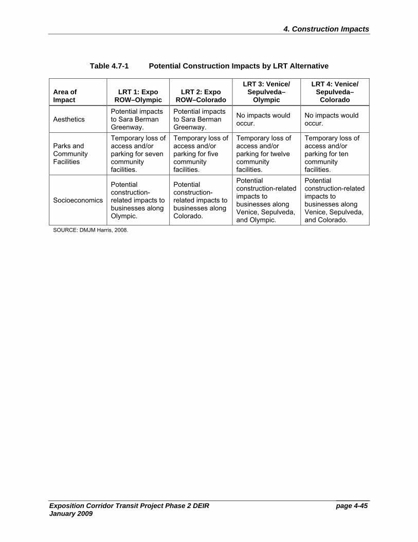
page 4-45
4. Construction Impacts
Exposition Corridor Transit Project Phase 2 DEIR January 2009
Table 4.7-1 Potential Construction Impacts by LRT Alternative
Area of Impact
LRT 1: Expo ROW–Olympic
LRT 2: Expo ROW–Colorado
LRT 3: Venice/ Sepulveda–
Olympic
LRT 4: Venice/ Sepulveda–
Colorado
Aesthetics Potential impacts to Sara Berman Greenway.
Potential impacts to Sara Berman Greenway.
No impacts would occur.
No impacts would occur.
Parks and Community Facilities
Temporary loss of access and/or parking for seven community facilities.
Temporary loss of access and/or parking for five community facilities.
Temporary loss of access and/or parking for twelve community facilities.
Temporary loss of access and/or parking for ten community facilities.
Socioeconomics
Potential construction-related impacts to businesses along Olympic.
Potential construction-related impacts to businesses along Colorado.
Potential construction-related impacts to businesses along Venice, Sepulveda, and Olympic.
Potential construction-related impacts to businesses along Venice, Sepulveda, and Colorado.
SOURCE: DMJM Harris, 2008.