Embed Size (px)
Citation preview
4. Carbon Capture in Natural Gas Combined Cycle plants (cont.)Laura Herraiz ([email protected])PGRAInstitute for Energy Systems, The University of Edinburgh, UK
CO2 Capture Workshop, Mexico, January 2018
4.2. Alternatives to optimise PCC system integration in Natural Gas Combined Cycle plants
4.2.1 Exhaust Gas Recirculation
4.2.2 Selective Exhaust Gas Recirculation
4.2.3 Supplementary Fired Combined Cycle
4.2.4. Sequential Supplementary Fired Combined Cycle
4.2.5. Gas Turbine humidification
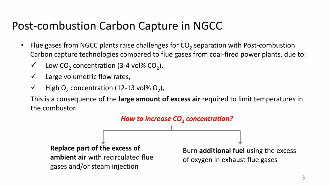
Post-combustion Carbon Capture in NGCC
• Flue gases from NGCC plants raise challenges for CO2 separation with Post-combustion Carbon capture technologies compared to flue gases from coal-fired power plants, due to:
Low CO2 concentration (3-4 vol% CO2),
Large volumetric flow rates,
High O2 concentration (12-13 vol% O2),
This is a consequence of the large amount of excess air required to limit temperatures in the combustor.
3
Replace part of the excess of ambient air with recirculated flue gases and/or steam injection
Burn additional fuel using the excess of oxygen in exhaust flue gases
How to increase CO2 concentration?
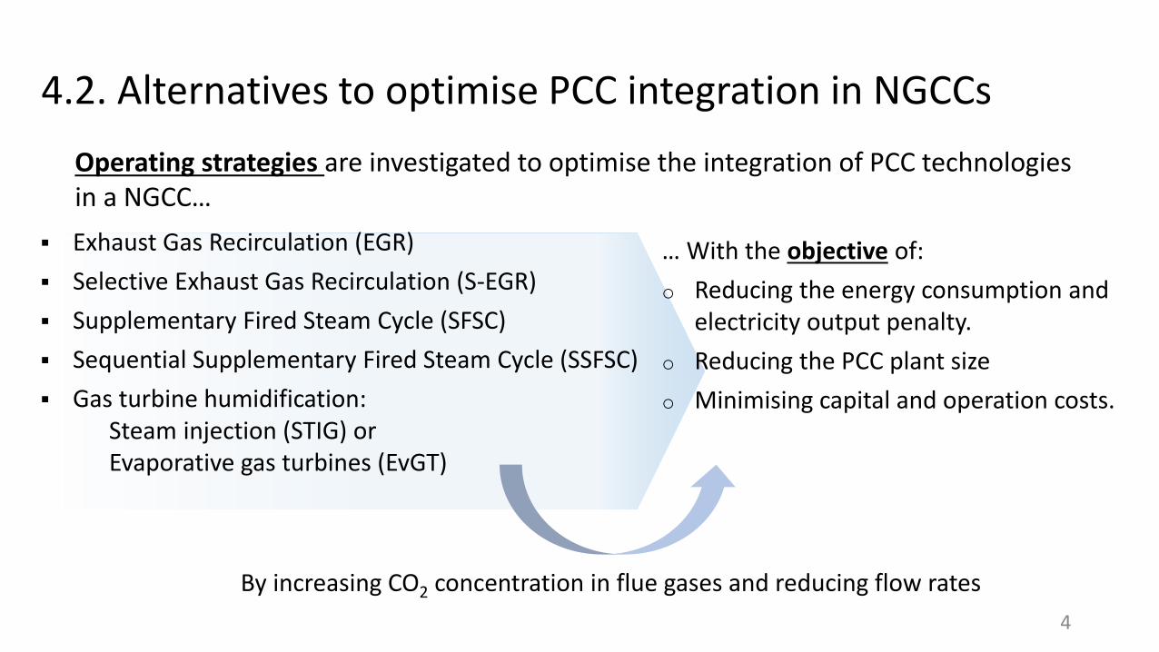
4.2. Alternatives to optimise PCC integration in NGCCs
Exhaust Gas Recirculation (EGR)
Selective Exhaust Gas Recirculation (S-EGR)
Supplementary Fired Steam Cycle (SFSC)
Sequential Supplementary Fired Steam Cycle (SSFSC)
Gas turbine humidification: Steam injection (STIG) or Evaporative gas turbines (EvGT)
Operating strategies are investigated to optimise the integration of PCC technologies in a NGCC…
… With the objective of:
o Reducing the energy consumption and electricity output penalty.
o Reducing the PCC plant size
o Minimising capital and operation costs.
By increasing CO2 concentration in flue gases and reducing flow rates
4
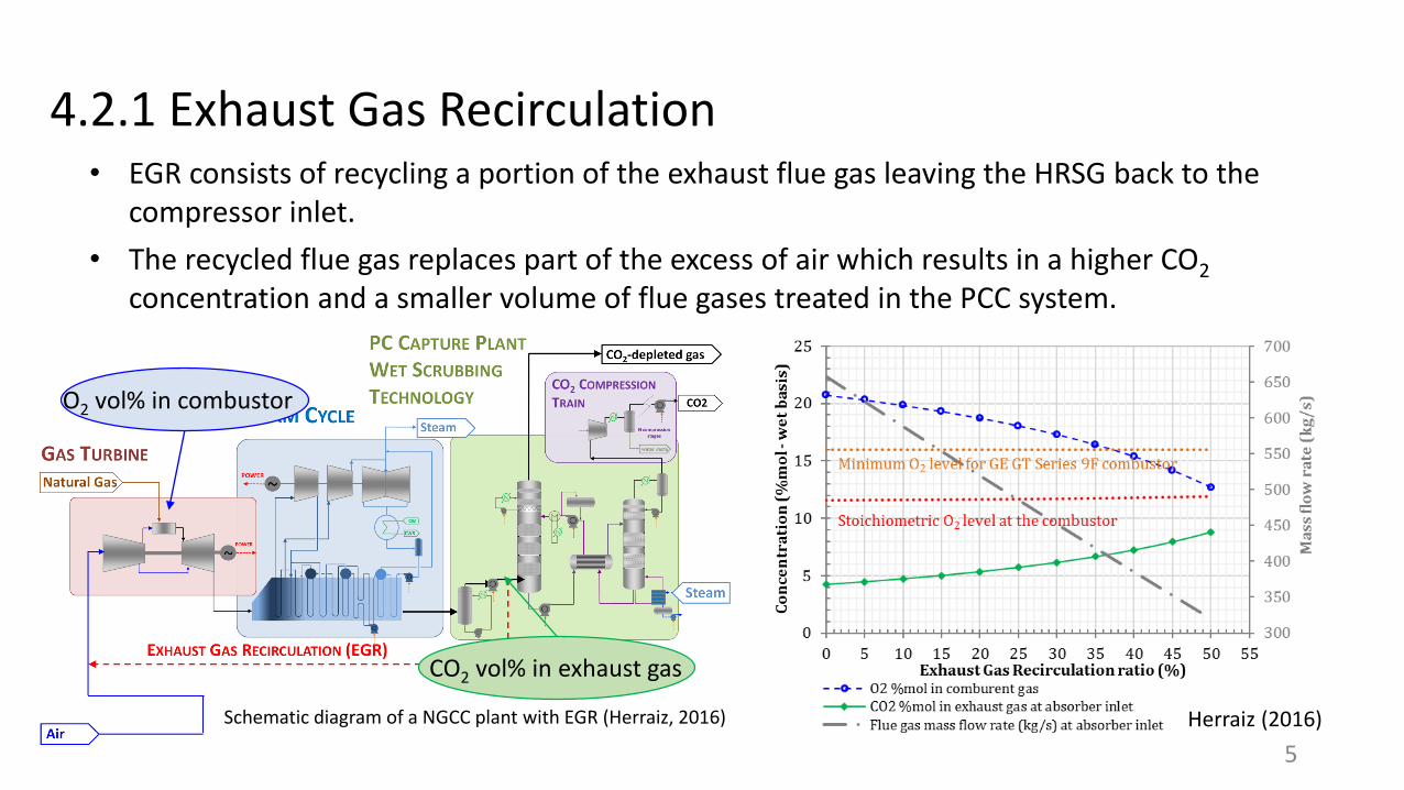
4.2.1 Exhaust Gas Recirculation • EGR consists of recycling a portion of the exhaust flue gas leaving the HRSG back to the
compressor inlet.
• The recycled flue gas replaces part of the excess of air which results in a higher CO2
concentration and a smaller volume of flue gases treated in the PCC system.
Schematic diagram of a NGCC plant with EGR (Herraiz, 2016)
O2 vol% in combustor
CO2 vol% in exhaust gas
Herraiz (2016)
5
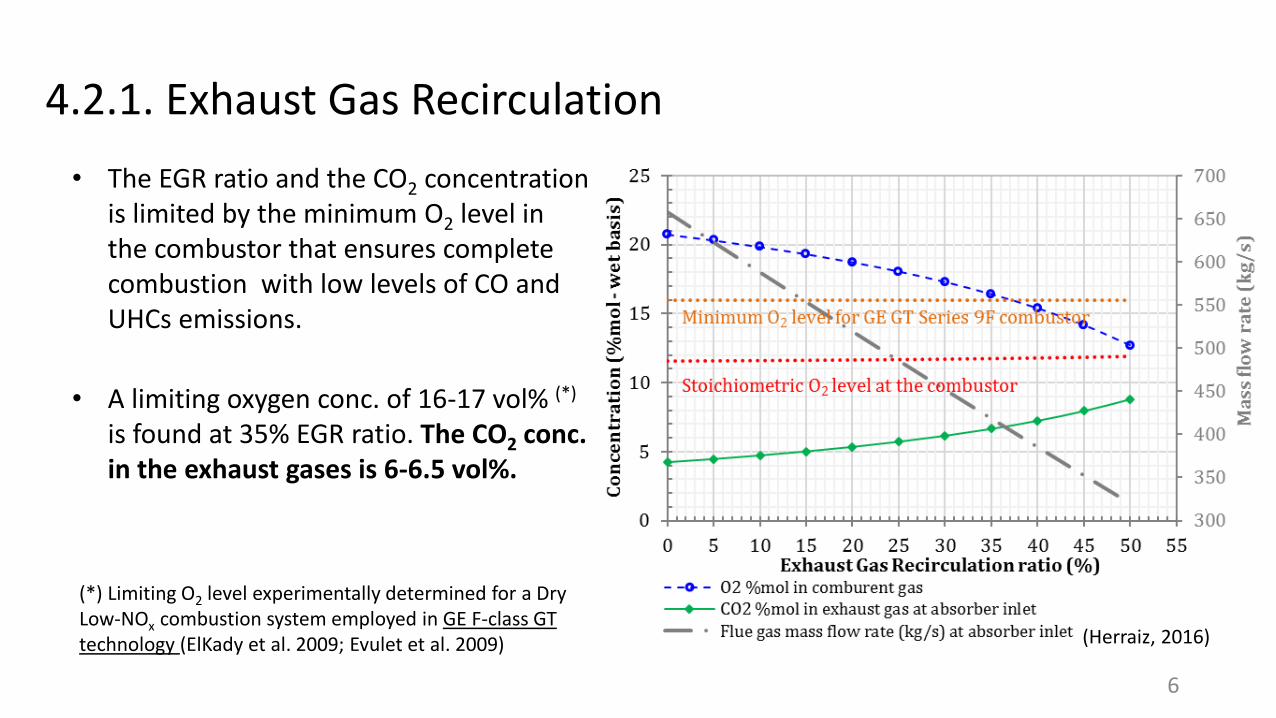
4.2.1. Exhaust Gas Recirculation
• The EGR ratio and the CO2 concentration is limited by the minimum O2 level in the combustor that ensures complete combustion with low levels of CO and UHCs emissions.
(Herraiz, 2016)
• A limiting oxygen conc. of 16-17 vol% (*)
is found at 35% EGR ratio. The CO2 conc. in the exhaust gases is 6-6.5 vol%.
(*) Limiting O2 level experimentally determined for a Dry Low-NOx combustion system employed in GE F-class GT technology (ElKady et al. 2009; Evulet et al. 2009)
6
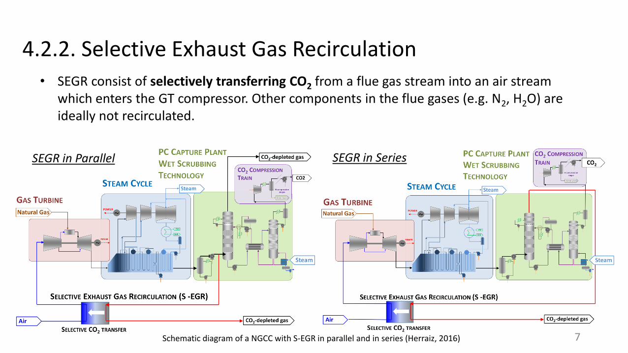
4.2.2. Selective Exhaust Gas Recirculation
• SEGR consist of selectively transferring CO2 from a flue gas stream into an air stream which enters the GT compressor. Other components in the flue gases (e.g. N2, H2O) are ideally not recirculated.
Schematic diagram of a NGCC with S-EGR in parallel and in series (Herraiz, 2016)
SEGR in Parallel SEGR in Series
7
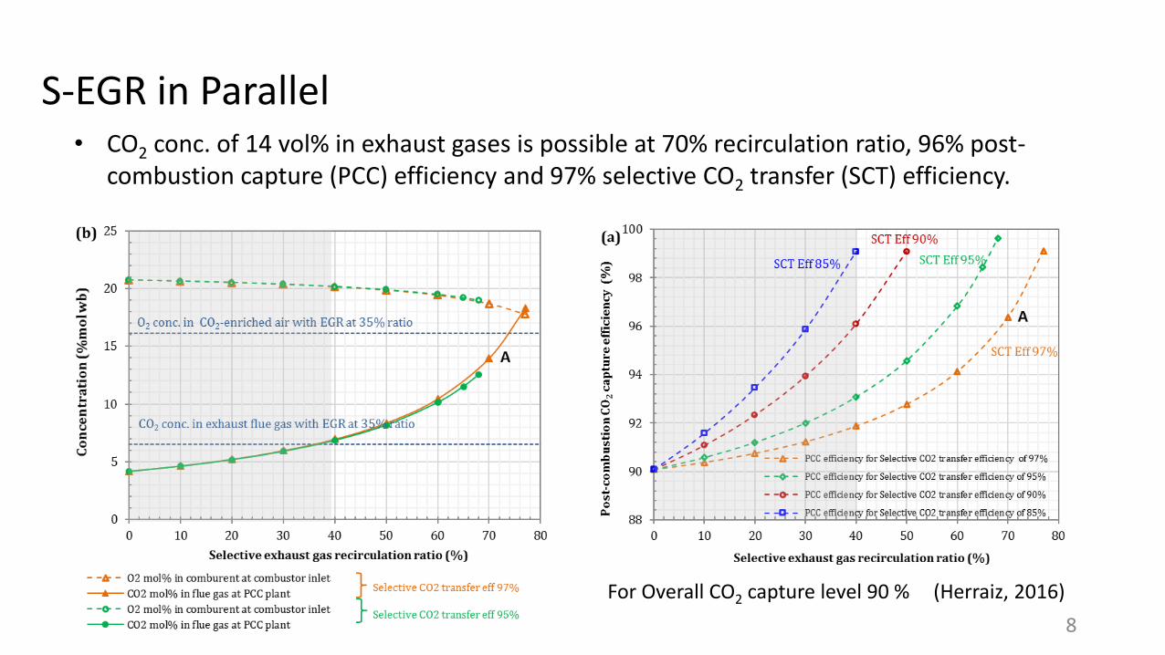
S-EGR in Parallel • CO2 conc. of 14 vol% in exhaust gases is possible at 70% recirculation ratio, 96% post-
combustion capture (PCC) efficiency and 97% selective CO2 transfer (SCT) efficiency.
(Herraiz, 2016)
8
For Overall CO2 capture level 90 %
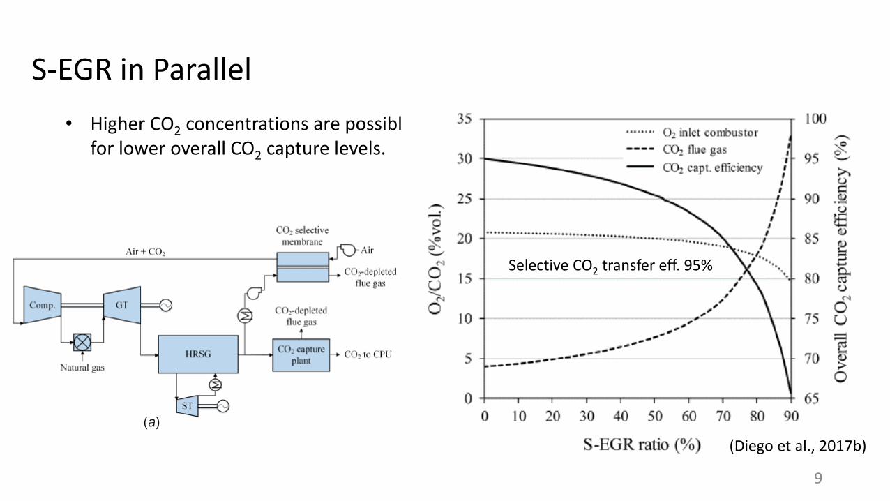
S-EGR in Parallel
• Higher CO2 concentrations are possible for lower overall CO2 capture levels.
9
(Diego et al., 2017b)
Selective CO2 transfer eff. 95%
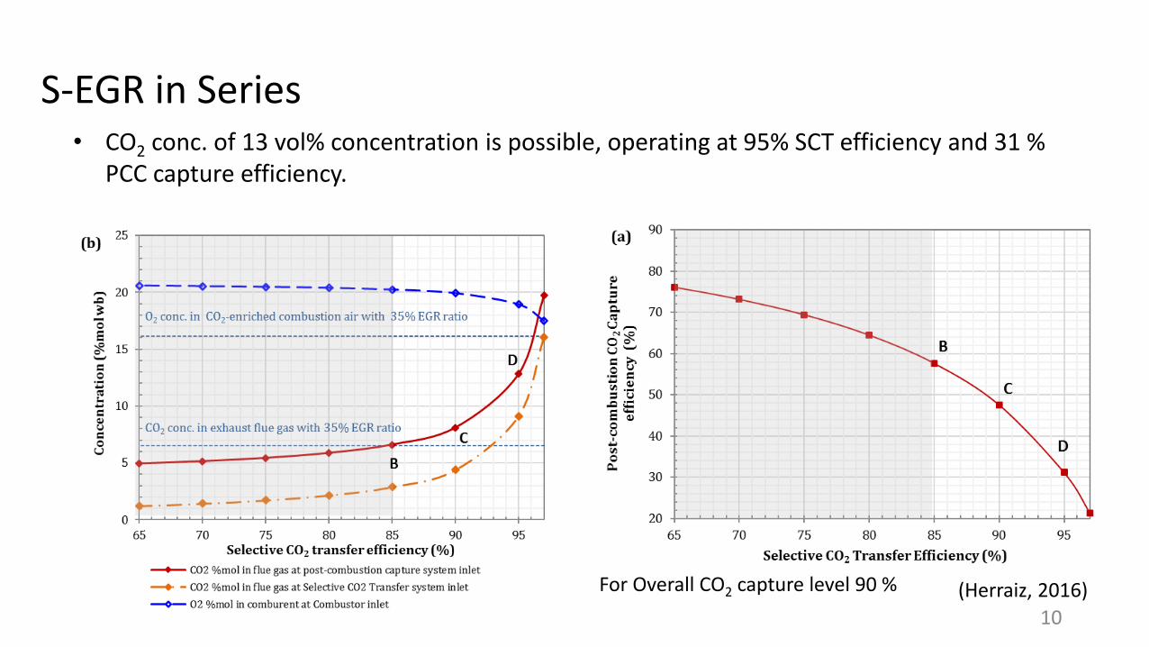
S-EGR in Series• CO2 conc. of 13 vol% concentration is possible, operating at 95% SCT efficiency and 31 %
PCC capture efficiency.
(Herraiz, 2016)
10
For Overall CO2 capture level 90 %
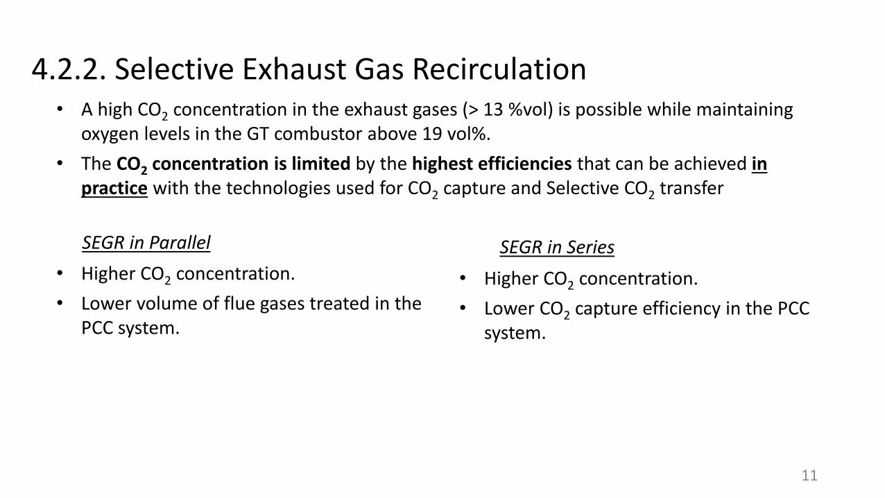
4.2.2. Selective Exhaust Gas Recirculation • A high CO2 concentration in the exhaust gases (> 13 %vol) is possible while maintaining
oxygen levels in the GT combustor above 19 vol%.
• The CO2 concentration is limited by the highest efficiencies that can be achieved in practice with the technologies used for CO2 capture and Selective CO2 transfer
SEGR in Parallel SEGR in Series
• Higher CO2 concentration.
• Lower volume of flue gases treated in the PCC system.
• Higher CO2 concentration.
• Lower CO2 capture efficiency in the PCC system.
11
• Compared to a conventional configuration of NGCC with PCC …..
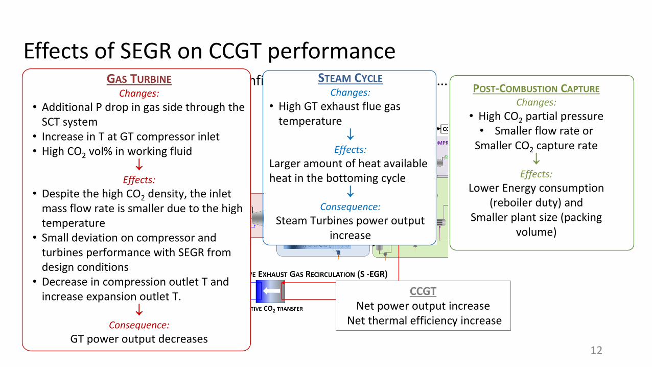
Effects of SEGR on CCGT performance STEAM CYCLE
Changes:
• High GT exhaust flue gas temperature
Effects:
Larger amount of heat available heat in the bottoming cycle
Consequence:
Steam Turbines power output increase
GAS TURBINE
Changes:
• Additional P drop in gas side through the SCT system
• Increase in T at GT compressor inlet • High CO2 vol% in working fluid
Effects:
• Despite the high CO2 density, the inlet mass flow rate is smaller due to the high temperature
• Small deviation on compressor and turbines performance with SEGR from design conditions
• Decrease in compression outlet T and increase expansion outlet T.
Consequence:
GT power output decreases12
POST-COMBUSTION CAPTURE
Changes:
• High CO2 partial pressure • Smaller flow rate or
Smaller CO2 capture rate
Effects:
Lower Energy consumption (reboiler duty) and
Smaller plant size (packing volume)
CCGT Net power output increase
Net thermal efficiency increase
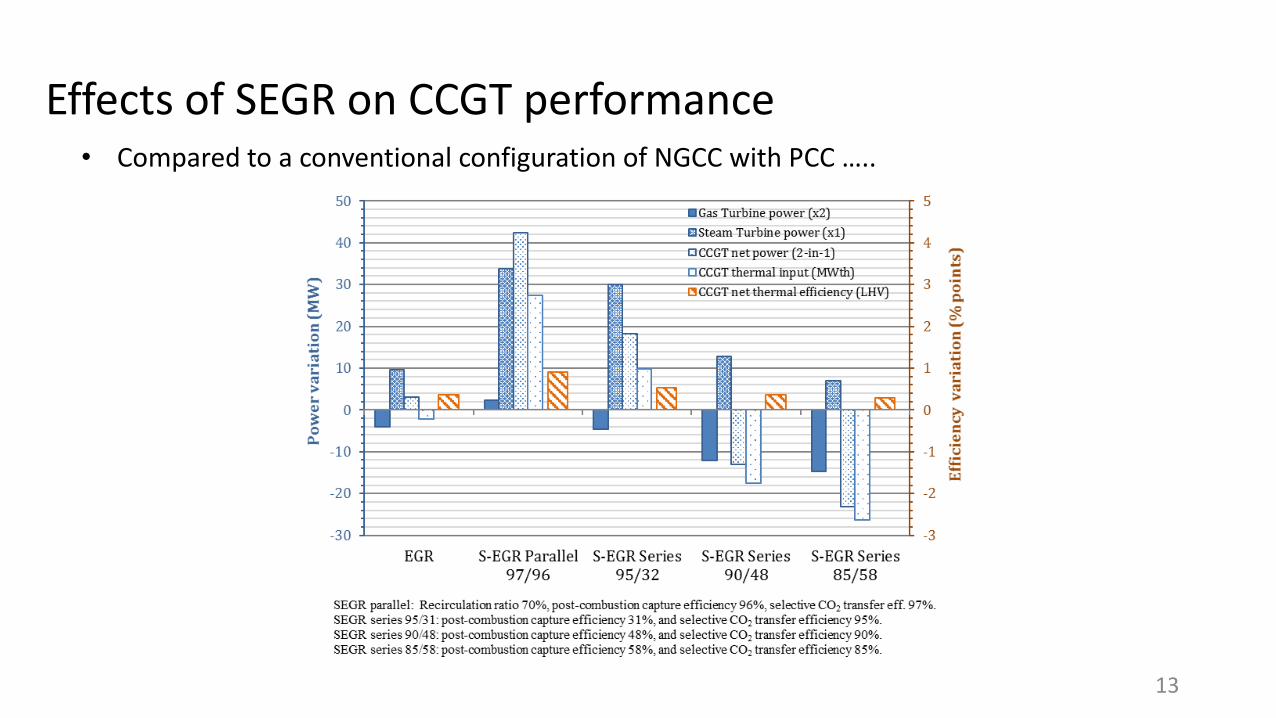
• Compared to a conventional configuration of NGCC with PCC …..
Effects of SEGR on CCGT performance
13

Effects of SEGR on the GT combustion system
14
• The technical challenges of S-EGR are associated to the combustion system, since CO2 acts as a combustion inhibitor and high concentrations would lead to flame instability, blow-off and eventual extinction of the flame.
• Effect of S-EGR on the Combustion system has been experimentally investigated at the Gas Turbine Research Center at Cardiff, UK (Marsh, 2016) under the scope of the SELECT project.
http://www.cu-gtrc.co.uk/
Effects of SEGR on GT combustion system
15
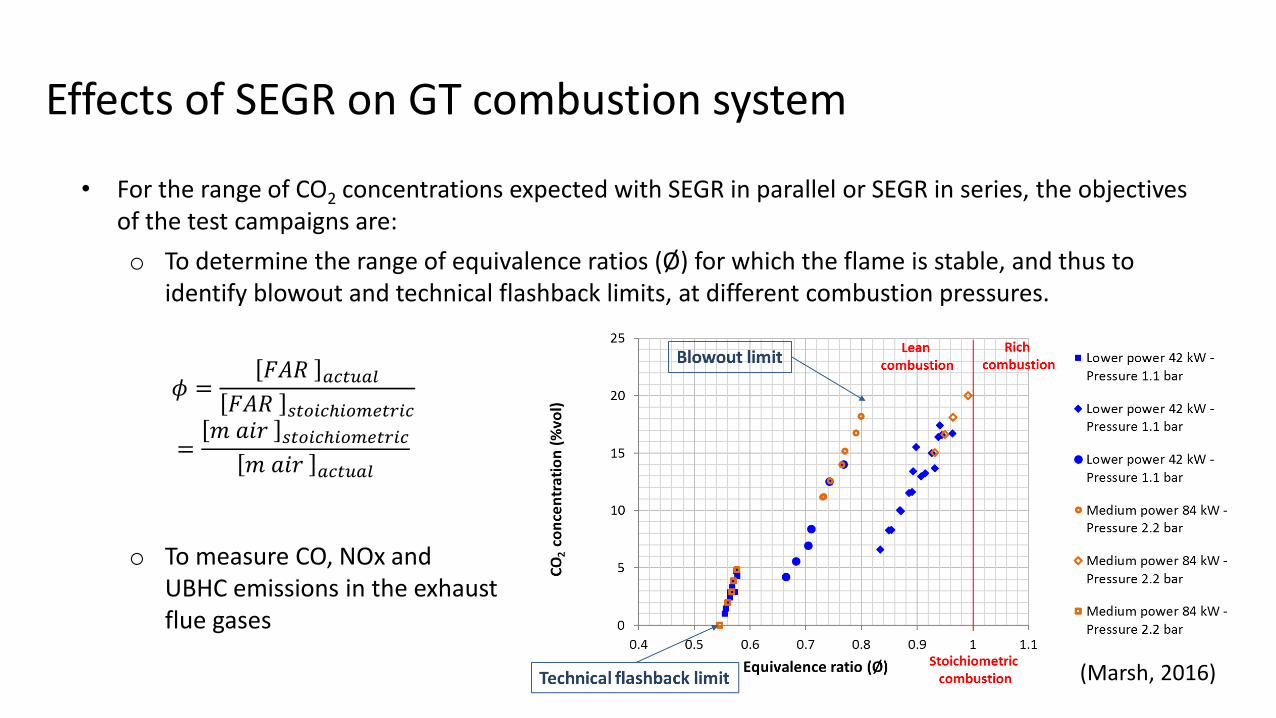
• For the range of CO2 concentrations expected with SEGR in parallel or SEGR in series, the objectives of the test campaigns are:
o To determine the range of equivalence ratios (Ø) for which the flame is stable, and thus to identify blowout and technical flashback limits, at different combustion pressures.
o To measure CO, NOx and UBHC emissions in the exhaust flue gases
𝜙 =𝐹𝐴𝑅 𝑎𝑐𝑡𝑢𝑎𝑙
𝐹𝐴𝑅 𝑠𝑡𝑜𝑖𝑐ℎ𝑖𝑜𝑚𝑒𝑡𝑟𝑖𝑐
=𝑚 𝑎𝑖𝑟 𝑠𝑡𝑜𝑖𝑐ℎ𝑖𝑜𝑚𝑒𝑡𝑟𝑖𝑐
𝑚 𝑎𝑖𝑟 𝑎𝑐𝑡𝑢𝑎𝑙
(Marsh, 2016)
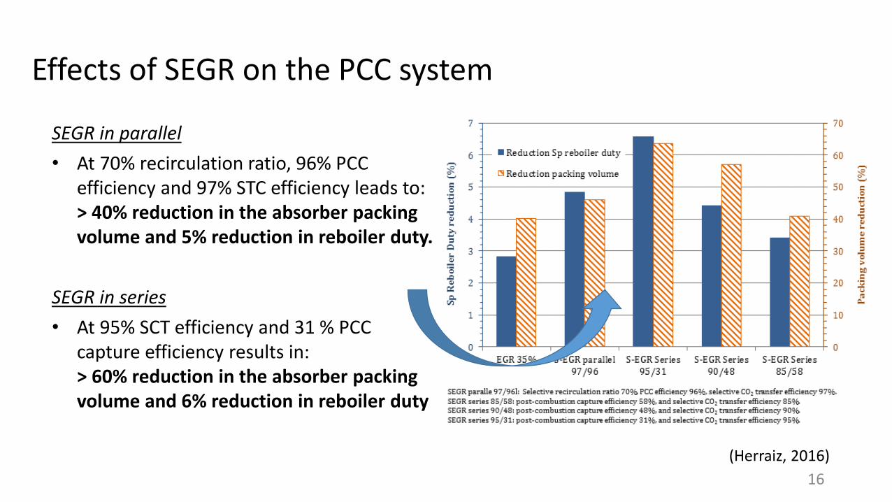
Effects of SEGR on the PCC system
(Herraiz, 2016)
SEGR in parallel
• At 70% recirculation ratio, 96% PCC efficiency and 97% STC efficiency leads to: > 40% reduction in the absorber packing volume and 5% reduction in reboiler duty.
SEGR in series
• At 95% SCT efficiency and 31 % PCC capture efficiency results in: > 60% reduction in the absorber packing volume and 6% reduction in reboiler duty
16
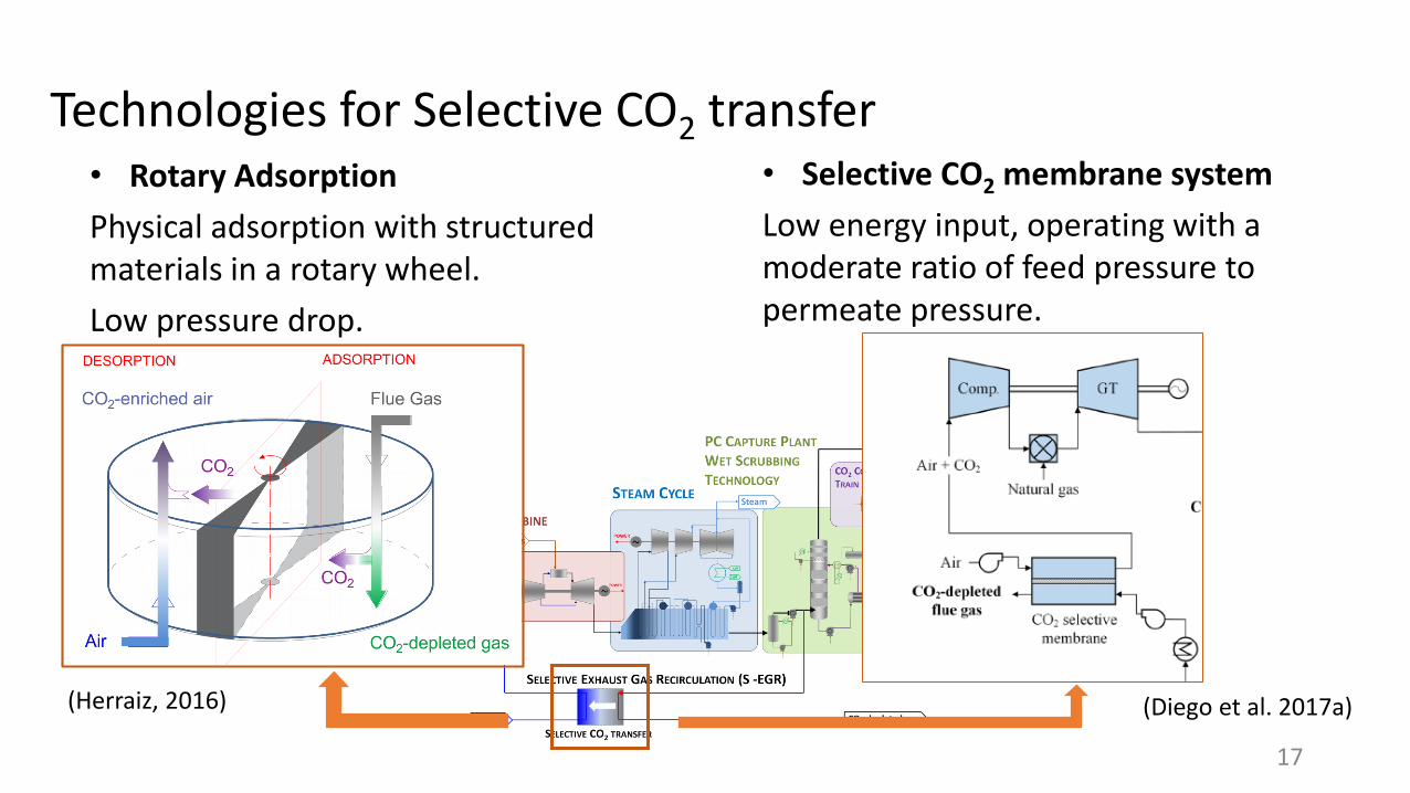
Technologies for Selective CO2 transfer • Rotary Adsorption
Physical adsorption with structured materials in a rotary wheel.
Low pressure drop.
(Herraiz, 2016) (Diego et al. 2017a)
• Selective CO2 membrane system
Low energy input, operating with a moderate ratio of feed pressure to permeate pressure.
17
Technologies for Selective CO2 transfer
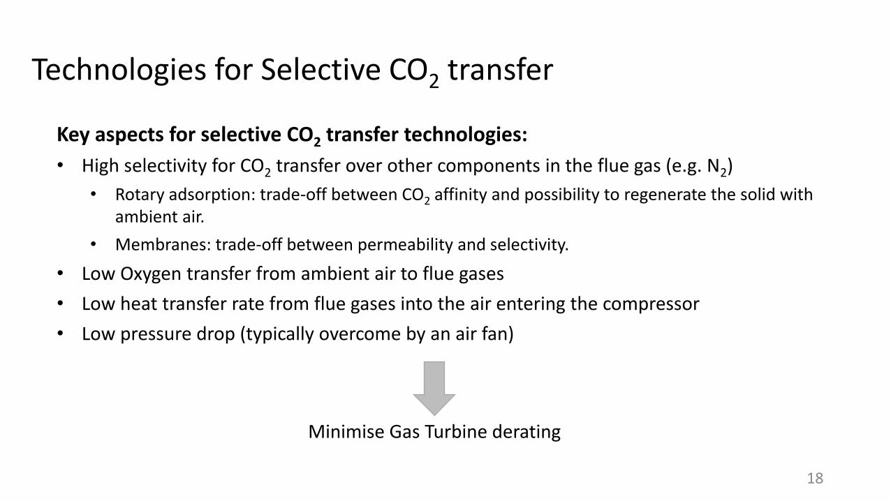
Key aspects for selective CO2 transfer technologies:
• High selectivity for CO2 transfer over other components in the flue gas (e.g. N2)
• Rotary adsorption: trade-off between CO2 affinity and possibility to regenerate the solid with ambient air.
• Membranes: trade-off between permeability and selectivity.
• Low Oxygen transfer from ambient air to flue gases
• Low heat transfer rate from flue gases into the air entering the compressor
• Low pressure drop (typically overcome by an air fan)
18
Minimise Gas Turbine derating
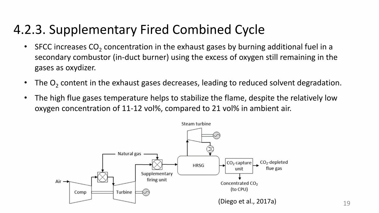
4.2.3. Supplementary Fired Combined Cycle• SFCC increases CO2 concentration in the exhaust gases by burning additional fuel in a
secondary combustor (in-duct burner) using the excess of oxygen still remaining in the gases as oxydizer.
• The O2 content in the exhaust gases decreases, leading to reduced solvent degradation.
• The high flue gases temperature helps to stabilize the flame, despite the relatively low oxygen concentration of 11-12 vol%, compared to 21 vol% in ambient air.
19(Diego et al., 2017a)
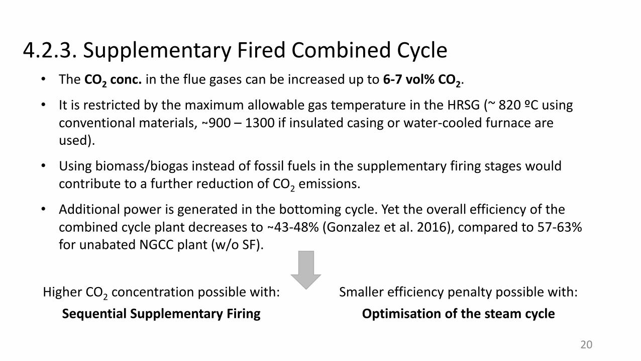
4.2.3. Supplementary Fired Combined Cycle• The CO2 conc. in the flue gases can be increased up to 6-7 vol% CO2.
• It is restricted by the maximum allowable gas temperature in the HRSG (~ 820 ºC using conventional materials, ~900 – 1300 if insulated casing or water-cooled furnace are used).
• Using biomass/biogas instead of fossil fuels in the supplementary firing stages would contribute to a further reduction of CO2 emissions.
• Additional power is generated in the bottoming cycle. Yet the overall efficiency of the combined cycle plant decreases to ~43-48% (Gonzalez et al. 2016), compared to 57-63% for unabated NGCC plant (w/o SF).
Higher CO2 concentration possible with:
Sequential Supplementary Firing
Smaller efficiency penalty possible with:
Optimisation of the steam cycle
20
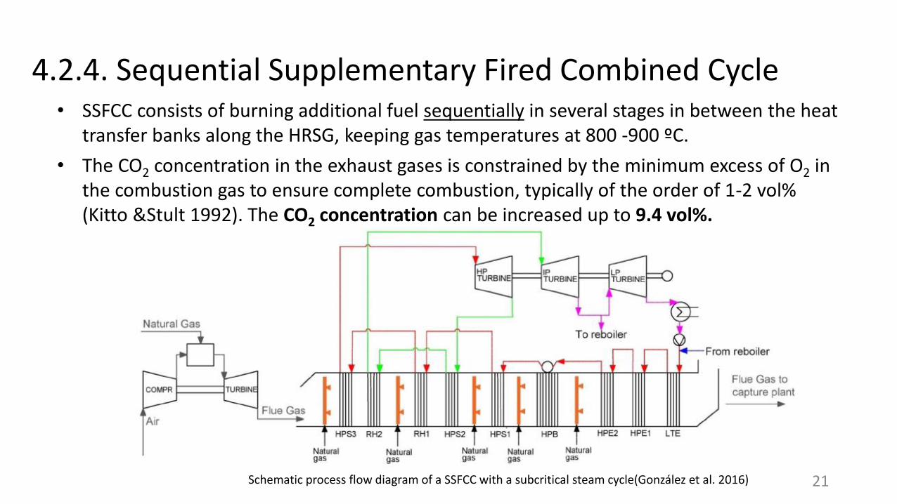
4.2.4. Sequential Supplementary Fired Combined Cycle • SSFCC consists of burning additional fuel sequentially in several stages in between the heat
transfer banks along the HRSG, keeping gas temperatures at 800 -900 ºC.
• The CO2 concentration in the exhaust gases is constrained by the minimum excess of O2 in the combustion gas to ensure complete combustion, typically of the order of 1-2 vol% (Kitto &Stult 1992). The CO2 concentration can be increased up to 9.4 vol%.
Schematic process flow diagram of a SSFCC with a subcritical steam cycle(González et al. 2016) 21
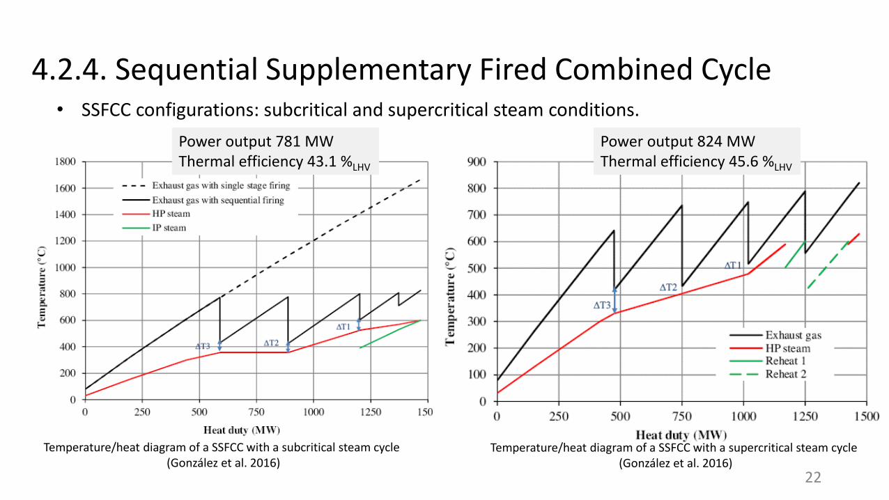
4.2.4. Sequential Supplementary Fired Combined Cycle • SSFCC configurations: subcritical and supercritical steam conditions.
Temperature/heat diagram of a SSFCC with a subcritical steam cycle(González et al. 2016)
Temperature/heat diagram of a SSFCC with a supercritical steam cycle(González et al. 2016)
Power output 781 MWThermal efficiency 43.1 %LHV
Power output 824 MWThermal efficiency 45.6 %LHV
22
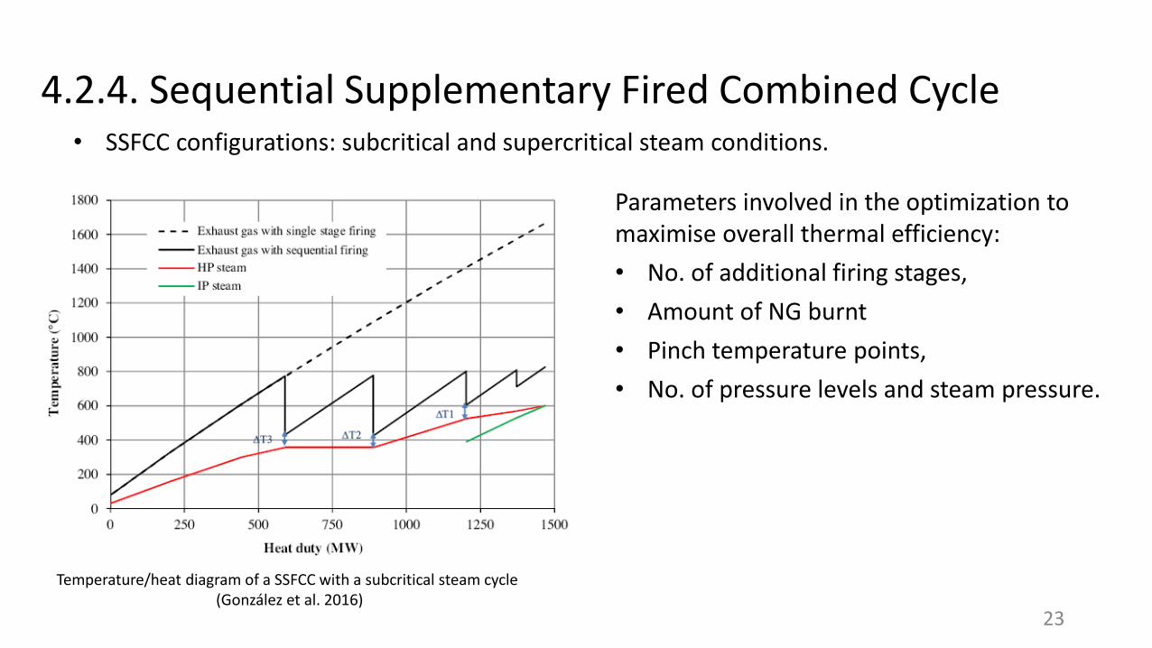
4.2.4. Sequential Supplementary Fired Combined Cycle • SSFCC configurations: subcritical and supercritical steam conditions.
Parameters involved in the optimization to maximise overall thermal efficiency:
• No. of additional firing stages,
• Amount of NG burnt
• Pinch temperature points,
• No. of pressure levels and steam pressure.
Temperature/heat diagram of a SSFCC with a subcritical steam cycle(González et al. 2016)
23
4.2.4. Sequential Supplementary Fired Combined Cycle
Technical performance, compared to a conventional CCGT with PCC:
• SSFCC presents a lower overall thermal efficiency (e.g. 43.1 %LHV vs. 51.3 %LHV)
• Yet, the higher steam turbines power generation leads to a reduction of the number of GT-HRSG trains (from 2 to 1) with a 50% reduction in flue gases flow rate, for the same power output.
• The capture plant size is significantly smaller.
Economic analysis: CCGT with SSFCC could be an attractive alternative for markets with access to competitive natural gas prices, with an emphasis on capital cost reduction, and were supply of carbon dioxide for Enhance Oil Recovery (EOR) is important.
24
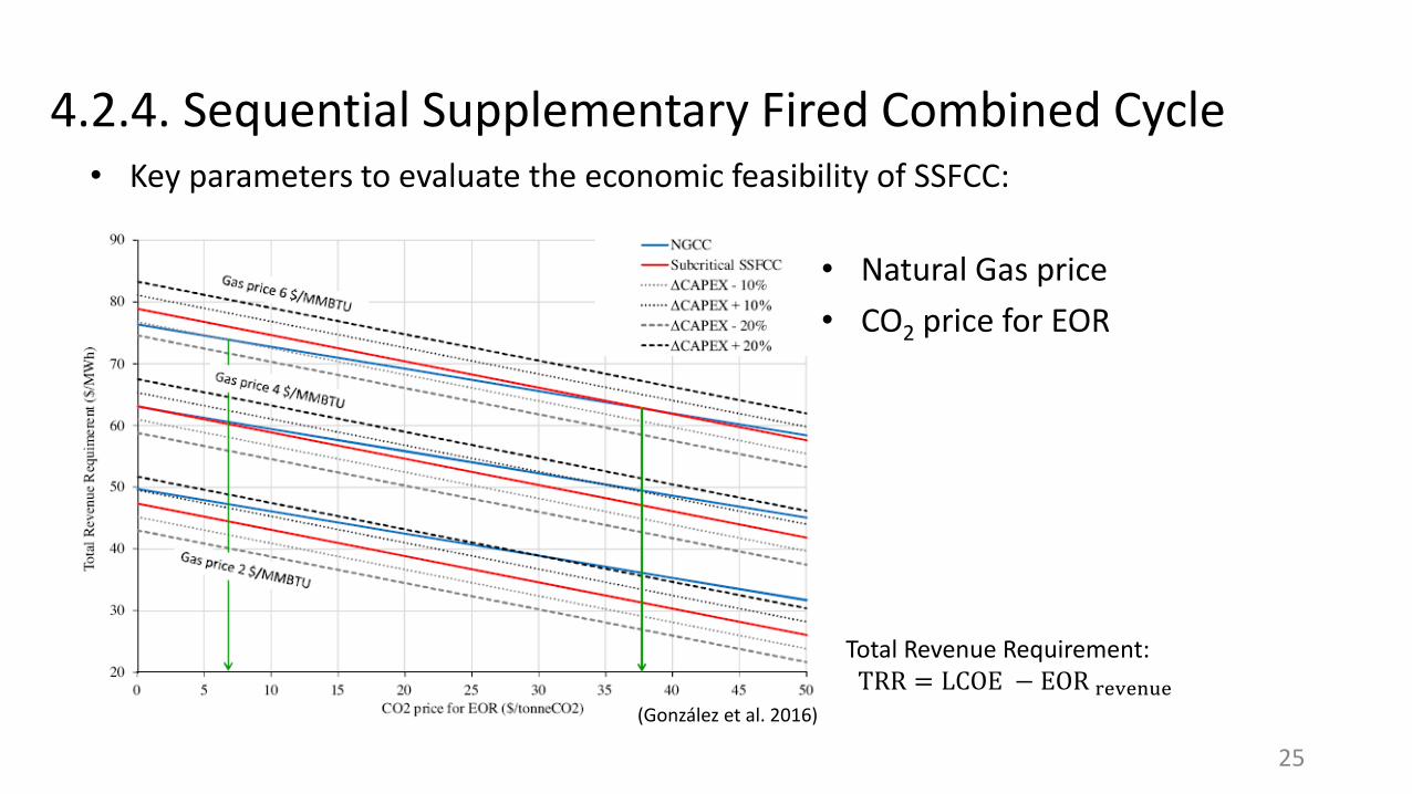
4.2.4. Sequential Supplementary Fired Combined Cycle • Key parameters to evaluate the economic feasibility of SSFCC:
• Natural Gas price
• CO2 price for EOR
Total Revenue Requirement:TRR = LCOE − EOR revenue
(González et al. 2016)
25
4.2.5. Gas turbine humidification
Water or steam replace part of the excess of air used for cooling. The water vapour can easily be separated from the flue gas by condensation, and a high CO2 concentrations in the flue gas are possible, compared to conventional GTs.
• Inlet air cooling systems – limited by ambient air relative humidity and T
• Combustion chamber injection systems
o Direct steam injection (STIG)
o Evaporative Gas Turbines (EvGT), where water injection in an humidification tower and evaporation.
26
The highest possible CO2 concentration depends on the water to air ratio (WAR) and on the cooled temperature of flue gas prior to entering the PCC plant.
4.2.5. Gas turbine humidification
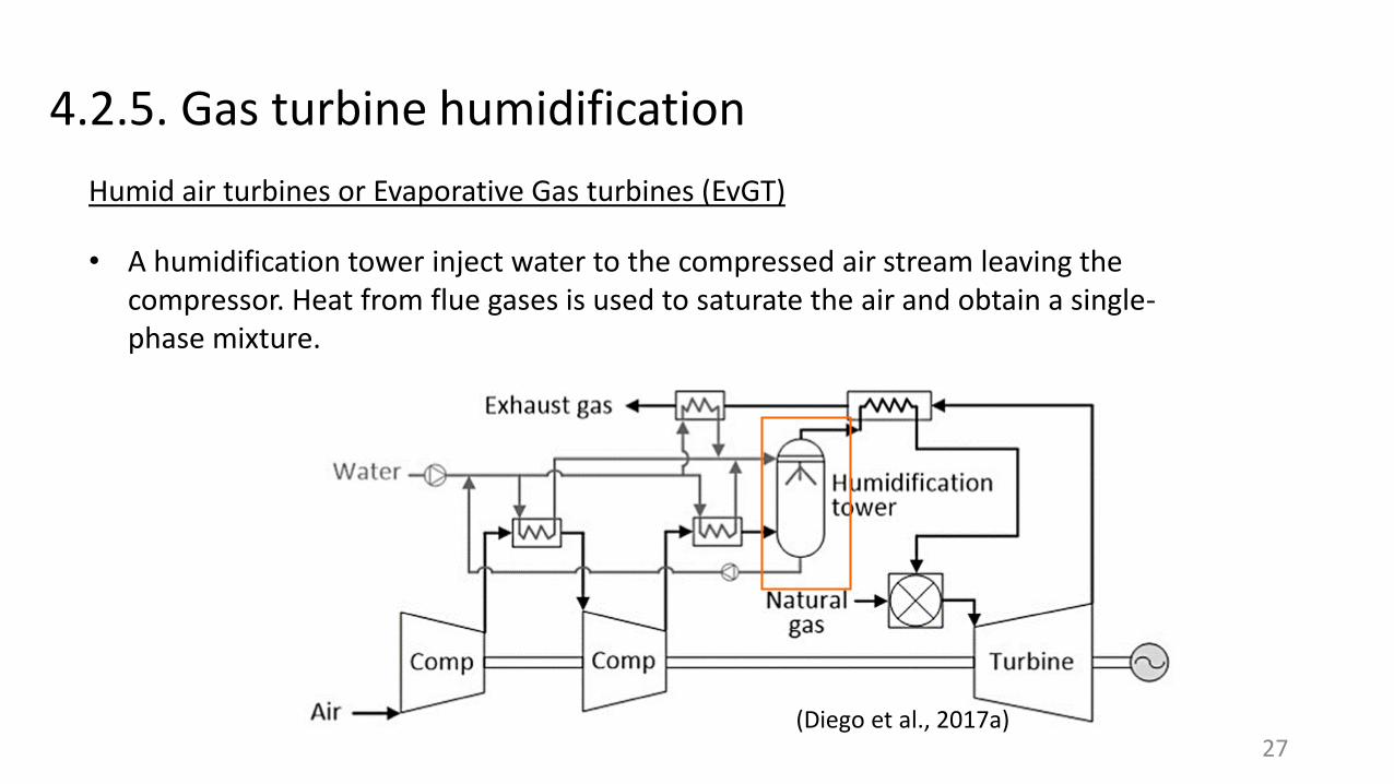
Humid air turbines or Evaporative Gas turbines (EvGT)
27(Diego et al., 2017a)
• A humidification tower inject water to the compressed air stream leaving the compressor. Heat from flue gases is used to saturate the air and obtain a single-phase mixture.
4.2.5. Gas turbine humidification
Humid air turbines or Evaporative Gas turbines (EvGT)
28
• EvGTs results in a higher power output due to a large mass flow rate through the expansion stages.
• EvGTs present a higher thermal efficiency compared to open-cycle GT but a lower compared to CCGTs (unless low-T heat is used for water evaporation).
• Yet suitable turbomachinery for HAT-systems still needs to be developed (to cope with flow mismatch between compressor and turbine)
• Limitations on the water to air ratio ( ~ 0.12 – 0.14, higher ratios may result in incomplete combustion and high CO and UHC emissions). Thus limited CO2 increase (up to 5 vol%) is possible.
4.2.5. Gas turbine humidification
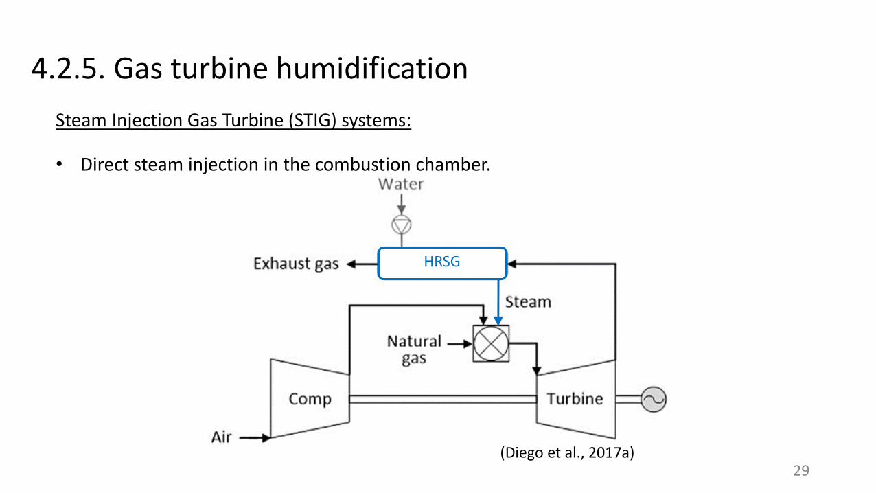
Steam Injection Gas Turbine (STIG) systems:
29(Diego et al., 2017a)
• Direct steam injection in the combustion chamber.
HRSG
4.2.5. Gas turbine humidification
30
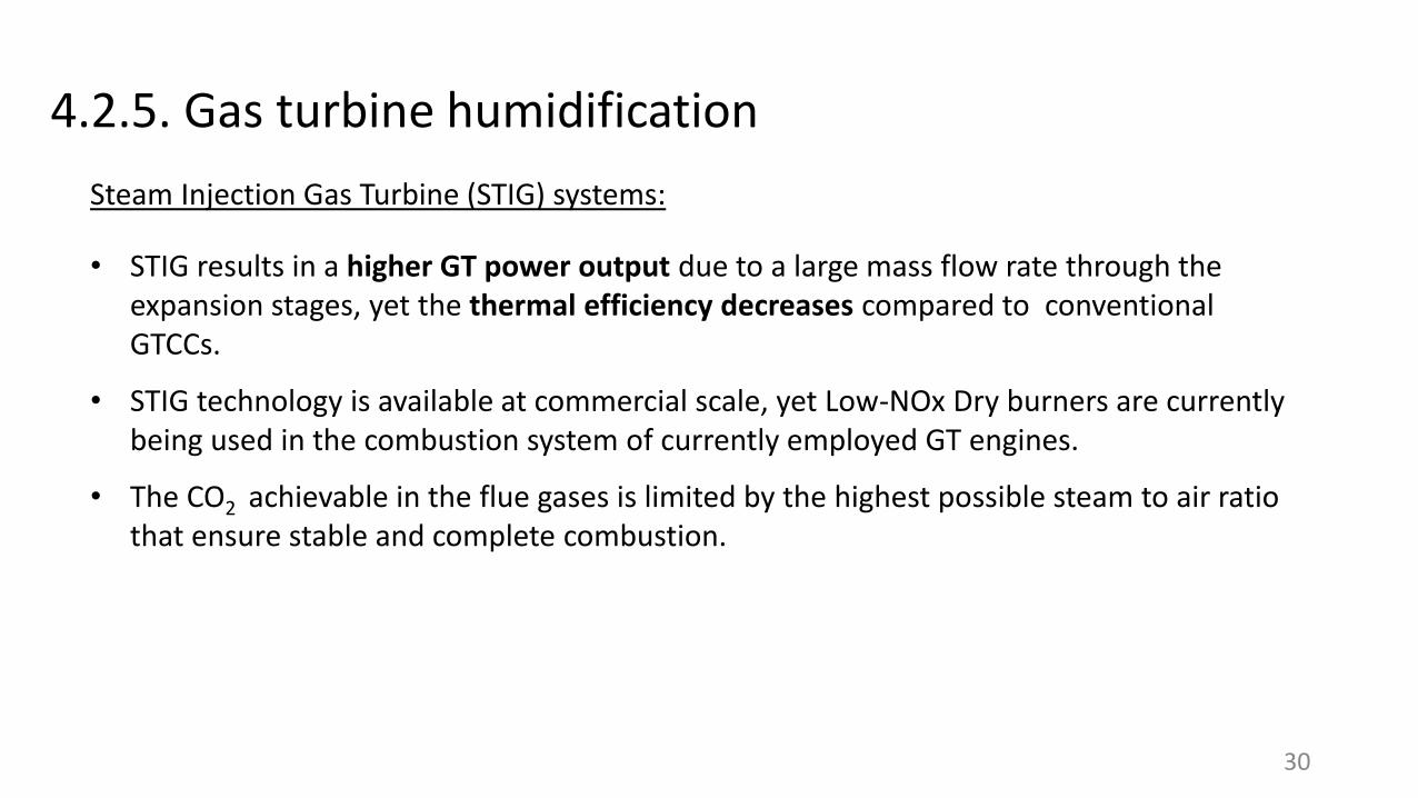
• STIG results in a higher GT power output due to a large mass flow rate through the expansion stages, yet the thermal efficiency decreases compared to conventional GTCCs.
• STIG technology is available at commercial scale, yet Low-NOx Dry burners are currently being used in the combustion system of currently employed GT engines.
• The CO2 achievable in the flue gases is limited by the highest possible steam to air ratio that ensure stable and complete combustion.
Steam Injection Gas Turbine (STIG) systems:

4.2.5. Gas turbine humidification
31
• STIG results in a higher GT power output due to a large mass flow rate through the expansion stages, yet the thermal efficiency decreases compared to conventional GTCCs.
• STIG technology is available at commercial scale, yet Low-NOx Dry burners are currently being used in the combustion system of currently employed GT engines.
• The CO2 achievable in the flue gases is limited by the highest possible steam to air ratio that ensure stable and complete combustion.
Steam Injection Gas Turbine (STIG) systems:
4.3. Summary
32
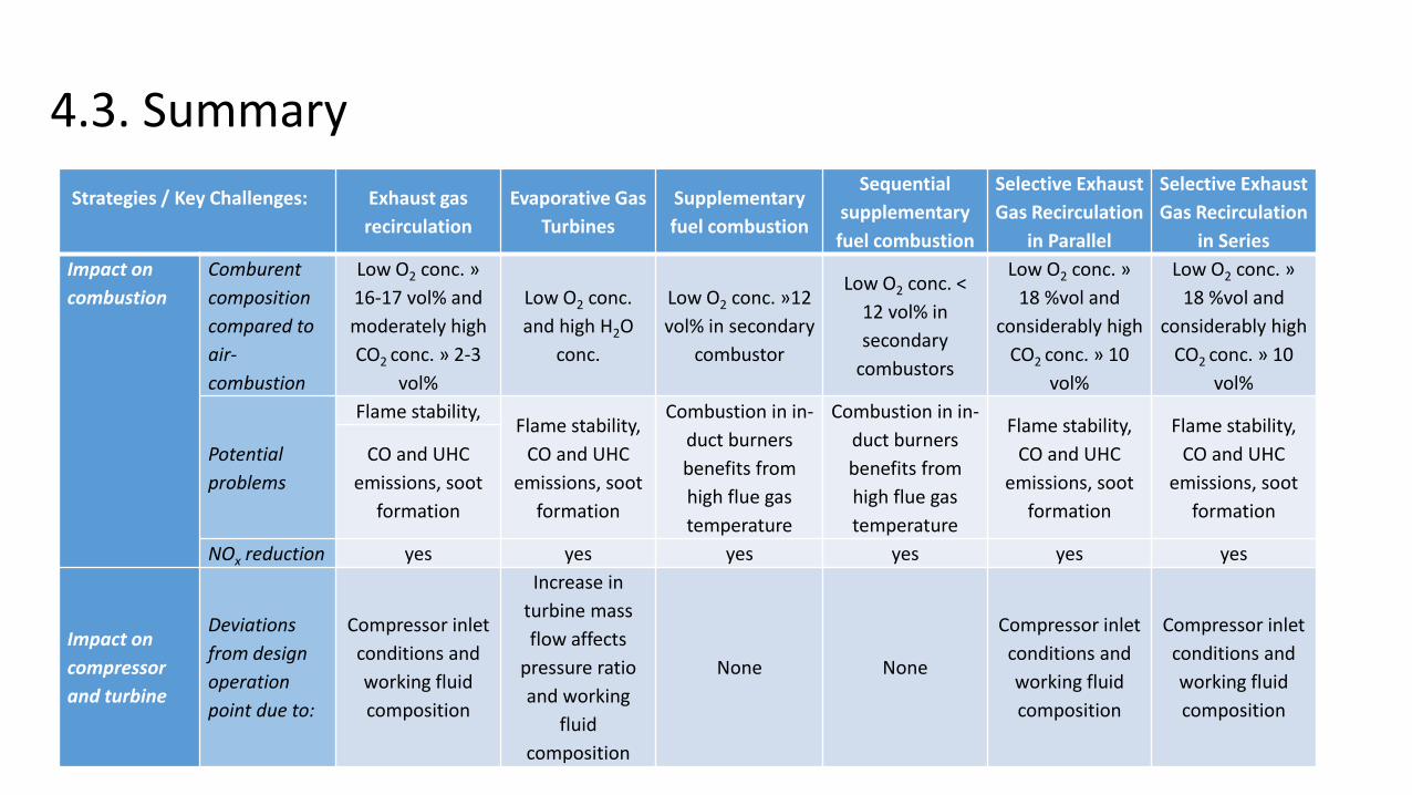
Strategies / Key Challenges: Exhaust gas
recirculation
Evaporative Gas
Turbines
Supplementary
fuel combustion
Sequential
supplementary
fuel combustion
Selective Exhaust
Gas Recirculation
in Parallel
Selective Exhaust
Gas Recirculation
in Series
Impact on
combustion
Comburent
composition
compared to
air-
combustion
Low O2 conc. »
16-17 vol% and
moderately high
CO2 conc. » 2-3
vol%
Low O2 conc.
and high H2O
conc.
Low O2 conc. »12
vol% in secondary
combustor
Low O2 conc. <
12 vol% in
secondary
combustors
Low O2 conc. »
18 %vol and
considerably high
CO2 conc. » 10
vol%
Low O2 conc. »
18 %vol and
considerably high
CO2 conc. » 10
vol%
Potential
problems
Flame stability,Flame stability,
CO and UHC
emissions, soot
formation
Combustion in in-
duct burners
benefits from
high flue gas
temperature
Combustion in in-
duct burners
benefits from
high flue gas
temperature
Flame stability,
CO and UHC
emissions, soot
formation
Flame stability,
CO and UHC
emissions, soot
formation
CO and UHC
emissions, soot
formation
NOx reduction yes yes yes yes yes yes
Impact on
compressor
and turbine
Deviations
from design
operation
point due to:
Compressor inlet
conditions and
working fluid
composition
Increase in
turbine mass
flow affects
pressure ratio
and working
fluid
composition
None None
Compressor inlet
conditions and
working fluid
composition
Compressor inlet
conditions and
working fluid
composition
4.3. Summary
33
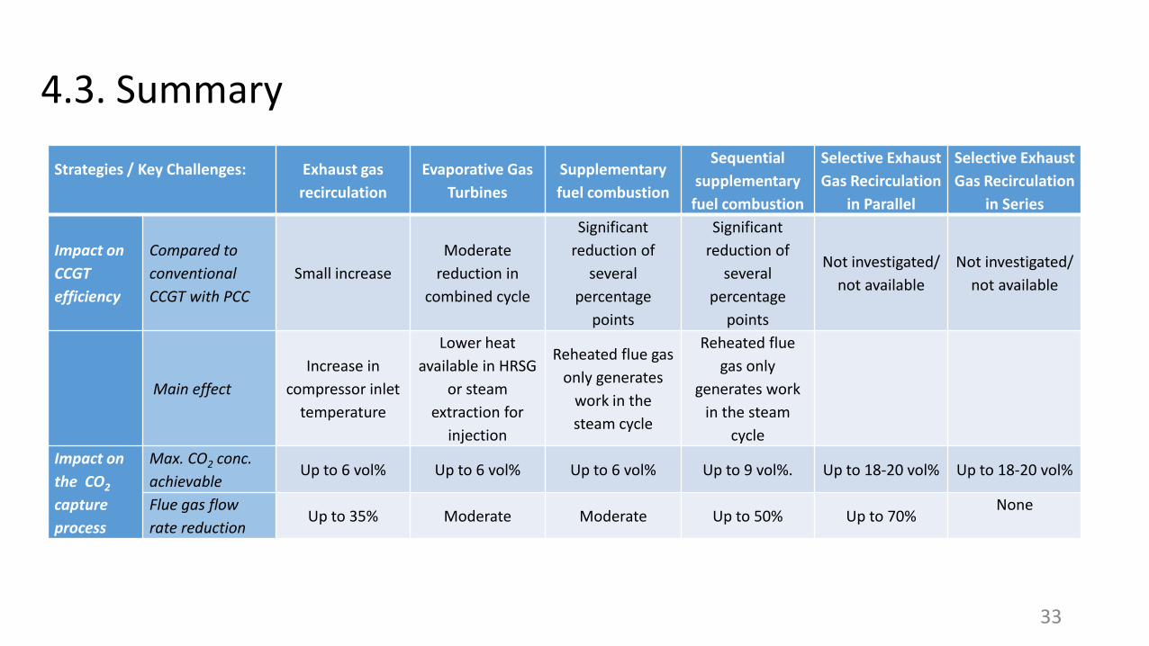
Strategies / Key Challenges: Exhaust gas
recirculation
Evaporative Gas
Turbines
Supplementary
fuel combustion
Sequential
supplementary
fuel combustion
Selective Exhaust
Gas Recirculation
in Parallel
Selective Exhaust
Gas Recirculation
in Series
Impact on
CCGT
efficiency
Compared to
conventional
CCGT with PCC
Small increase
Moderate
reduction in
combined cycle
Significant
reduction of
several
percentage
points
Significant
reduction of
several
percentage
points
Not investigated/
not available
Not investigated/
not available
Main effect
Increase in
compressor inlet
temperature
Lower heat
available in HRSG
or steam
extraction for
injection
Reheated flue gas
only generates
work in the
steam cycle
Reheated flue
gas only
generates work
in the steam
cycle
Impact on
the CO2
capture
process
Max. CO2 conc.
achievableUp to 6 vol% Up to 6 vol% Up to 6 vol% Up to 9 vol%. Up to 18-20 vol% Up to 18-20 vol%
Flue gas flow
rate reductionUp to 35% Moderate Moderate Up to 50% Up to 70%
None
34
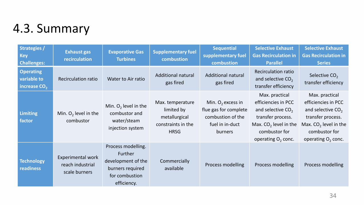
Strategies /
Key
Challenges:
Exhaust gas
recirculation
Evaporative Gas
Turbines
Supplementary fuel
combustion
Sequential
supplementary fuel
combustion
Selective Exhaust
Gas Recirculation in
Parallel
Selective Exhaust
Gas Recirculation in
Series
Operating
variable to
increase CO2
Recirculation ratio Water to Air ratio Additional natural
gas fired
Additional natural
gas fired
Recirculation ratio
and selective CO2
transfer efficiency
Selective CO2
transfer efficiency
Limiting
factor
Min. O2 level in the
combustor
Min. O2 level in the
combustor and
water/steam
injection system
Max. temperature
limited by
metallurgical
constraints in the
HRSG
Min. O2 excess in
flue gas for complete
combustion of the
fuel in in-duct
burners
Max. practical
efficiencies in PCC
and selective CO2
transfer process.
Max. CO2 level in the
combustor for
operating O2 conc.
Max. practical
efficiencies in PCC
and selective CO2
transfer process.
Max. CO2 level in the
combustor for
operating O2 conc.
Technology
readiness
Experimental work
reach industrial
scale burners
Process modelling.
Further
development of the
burners required
for combustion
efficiency.
Commercially
availableProcess modelling Process modelling Process modelling
4.3. Summary
References• Diego, M.E., Akram, M., Bellas, J.M., Finney, K. N. and Pourkashanian, M. (2017). Making gas-CCS a commercial reality: The
challenges of scaling up.
• Diego, M.E., Bellas, J.M. and Pourkashanian, M. (2017) Process Analysis of Selective Exhaust Gas Recirculation for CO2 capture in Natural Gas Combined Cycle Power Plants Using Amines, J. of Engineering for Gas Turbines and Power, 139, 121701-1.
• ElKady, A. M., Evulet, A., Brand, A., Ursin, T. P. and Lynghjem, A. (2009) ‘Application of Exhaust Gas Recirculation in a DLN F-Class Combustion System for Postcombustion Carbon Capture’, J.l of Engineering for Gas Turbines and Power, 131(May 2009), p. 34505. doi: 10.1115/1.2982158.
• Evulet, A. T., ELKady, A. M., Branda, A. R. and Chinn, D. (2009) ‘On the Performance and Operability of GE’s Dry Low NOx Combustors utilizing Exhaust Gas Recirculation for PostCombustion Carbon Capture’, Energy Procedia, 1, 3809–3816.
• González Díaz, A., Sánchez Fernández, E., Gibbins, J. and Lucquiaud, M. (2016). Sequential supplementary firing in natural gas combined cycle with carbon capture: A technology option for Mexico for low-carbon electricity generation and CO2 enhanced oil recovery. Int. Journal of Greenhouse Gas Control, 51, 330-345.
• Herraiz, L. (2016) Selective Exhaust Gas Recirculation in Combined Cycle Gas Turbine power plants with Post-combustion Carbon Capture. The University of Edinburgh.
• Herraiz, L., Palfi, E., Sanchez Fernandez, E. and Lucquiaud, M. (2018) Selective Exhaust Gas Recirculation in Combined Cycle Gas Turbine power plants with Post-combustion Carbon Capture. Int. Journal of Greenhouse Gases, accepted.
35
References• Li, H., Ditaranto, M., Yan, J. (2012). Carbon capture with low energy penalty: supplementary fired natural gas combined
cycles. Appl. Energy, 97, 164-169.
• Marsh, R., Giles, A., Runyon, J., Pugh, D., Bowen, P., Morris, S., Valera-Medina, A., Best, T., Finney, K. and Pourkashanian, M. (2016) ‘Selective Exhaust Gas Recycling for Carbon Capture Applications: Combustion and Operability Measurement’, The Future of gas Turbine Technology 8th International Gas Turbine Conference, 12-13 October, Brussels, Belgium.
• Merkel, T. C., Wei, X., He, Z., White, L. S., Wijmans, J. G. and Baker, R. W. (2013) ‘Selective Exhaust Gas Recycle with Membranes for CO2 Capture from Natural Gas Combined Cycle Power Plants’, Industrial & Engineering Chemistry Research, 52, 1150–1159
• SELECT (2014) Selective Exhaust Gas Recirculation for Carbon Capture with Gas Turbines: Integration, Intensification, Scale-up and Optimisation. Available at: http://gow.epsrc.ac.uk/NGBOViewGrant.aspx?GrantRef=EP/M001482/1.
36
Carbon Capture in Natural Gas Combined Cycle plants (NGCC)Laura Herraiz ([email protected])PGRAInstitute for Energy Systems, The University of Edinburgh, UK
CO2 Capture Workshop, Mexico, January 2018


![BOYMOR.QLE QL.REP] - Stacksxk898wv6983/xk898wv6983.pdf · 15 jun 1978 6:55 boymor.qle ql,rep] page 1-1 (cont.) (cont.) (cont.) (cont.) (cont.) (cont.) prover prover (cont.) 5 comment](https://img.pdfslide.us/doc/110x75/6057337242a55f07515b3baa/qlrep-stacks-xk898wv6983xk898wv6983pdf-15-jun-1978-655-boymorqle-qlrep.jpg)


![[XLS]sagga.co.zasagga.co.za/images/Copy of Arch Spec Combined Matrix May... · Web view832065560 SAGGA - South African Glass & Glazing Association (Continue) GAUTENG (Cont.) Glazier](https://img.pdfslide.us/doc/110x75/5af3fdb47f8b9a74448c3ff9/xlssaggaco-of-arch-spec-combined-matrix-mayweb-view832065560-sagga-south.jpg)