Embed Size (px)
Citation preview

Activity Report
Verein Deutscher Zementwerke e.V.Forschungsinstitut der Zementindustrie
Vere
in D
euts
cher
Zem
entw
erke
e.V
.Fo
rsch
un
gsi
nst
itu
t d
er Z
emen
tin
du
stri
eA
ctiv
ity
Rep
ort
Verein Deutscher Zementwerke e.V.Forschungsinstitut der ZementindustriePostfach 30 10 63D-40410 DüsseldorfTannenstraße 2D-40476 Düsseldorf
2005
– 2
007
2005
– 2
007


VDZ Activity Report 2005 – 2007
Activity Report 2005 – 2007

VDZ Activity Report 2005 – 2007
The cover shows the view into the grinding chamber of a ball mill for raw material process-ing at a cement works. Ball mills are still widely used in the cement industry, especially for ce-ment grinding. This mill type excels by its high reliability and thus requires little maintenance. Given the rise in electrical power costs, the op-timisation of ball mills has assumed particular importance recently. The Research Institute of the Cement Industry investigated various ball mills in the period under review, indicating the potential for their optimisation. This allowed electrical power consumption to be reduced or throughput to be increased, respectively, in many cases.
Production:Verlag Bau+Technik GmbH, Düsseldorf
Verein Deutscher Zementwerke e.V.Forschungsinstitut der ZementindustriePostfach 30 10 63, D-40410 DüsseldorfTannenstraße 2, D-40476 DüsseldorfPhone: +49 (0) 211 45 78-1Fax: +49 (0) 211 45 [email protected]

VDZ Activity Report 2005 – 2007
Contents 4 Verein Deutscher Zementwerke e.V. Forschungsinstitut der Zementindustrie 6 Structure 7 Board of Directors 8 The German Cement Works Association 8 Committees, working groups and commissions 13 Cooperation with other organisations 15 Dissemination of findings 16 The Research Institute of the Cement Industry 19 Services
22 I Process technology of cement manufacture 24 Energy consumption 26 Energy requirement 28 Plant operation
42 II Environmental protection in cement manufacture 44 Legislation 48 Climate protection 54 Environmental data 55 Reducing gas and dust emissions 61 Sound proofing
62 III Performance of cement 64 Chemico-mineralogical composition 65 Reactivity of blastfurnace slags 68 Glass products derived from kiln dusts of the cement industry 71 Influence of the particle size distribution of main cement constituents 73 Investigations on the hydration of cement clinker phases 77 Radioscopic quantification of blastfurnace slag in cement 80 Sulphate resistance
82 IV Quality surveillance and quality assurance of cement 84 The VDZ’s quality surveillance organisation 88 Quality assurance 90 Standardisation 92 Methods of testing 94 Chromate reduction of cement
98 V Concrete constituents, concrete technology and concrete engineering 100 Cements with several main constituents 104 Cement and admixtures 112 Alkali-silica reaction 116 Durability 120 Fair-faced concrete 123 Self-compacting concrete 124 Ultra high performance concrete 126 Earth-dry concrete 126 Traffic route engineering 129 Structural fire protection 130 Modelling 133 Standardisation 138 Consultancy and expert’s advisory services
140 VI Environmental compatibility of cement and concrete 142 Environmental criteria for cement-based building materials 144 REACH145 European Construction Products Directive 147 DIBt Guideline “Assessment of the effects of construction products on soil and groundwater” 149 Cement-based materials in the drinking water domain 150 Sustainable building with concrete 152 Measuring and testing methods
154 VII Responsibility for employees 156 Safety at work 158 VDZ training and development
162 Publications
VDZ Activity Report 2005 – 2007
�Verein Deutscher Zementwerke e.V. Forschungsinstitut der Zementindustrie
The Research Institute of the Cement Industry in Düsseldorf
The German Cement Works Association has traditionally summarised its work in an Activity Report at regular intervals. The present report covers the period from 2005 to 2007. As always, it presents topics of cement manufacture and application that the Research Institute of the Cement Industry worked on as part of industrial joint research.
The challenges that cement research in Germany was facing in the past decade were characterised by a persistent recession in build-ing. The decline in cement dispatch, the increasingly international orientation of cement manufacturers, and the harmonisation of standards and environmental regulations at European level thus led to an extension of the areas of activity and prompted the Research Institute to adopt a new orientation. Thus, the Institute has increasingly positioned itself as a provider of services covering the entire cement and concrete domain. Based on the results of excellent research and its integration in the cement industry, the Institute gives advice on numerous topical questions of cement and concrete production to cement manufacturers and appliers. A wide range of state-of-the-art technical equipment and a team of highly qualified employees provide for an upscale service portfolio. As contractor services have been increasing, parts of the Institute will be operated as a limited liability company in the future.
Given the Institute’s reorientation, its expertise has been increasingly enlisted at European and worldwide level. As a result of its first-rate integration in international cement research and in the European cement association CEMBUREAU, as well as its co- operation with national and international cement manufacturers, the Institute has been acknowledged and enlisted as an international competence centre for cement and concrete. Cooperation has been intensified via the European Cement Research Academy (ecra), which the VDZ co-founded some years ago and which serves as the cornerstone for a European research platform.
The Institute’s building in Düsseldorf was committed to its present use in September 1957. A retrospective of 50 years of the Institute’s history shows that the Research Institute provides the German Cement Works Association with a powerful instrument for joint work. In this way, it is still ensured that the VDZ will continue to exist in its proven form and perform its statutory functions well into the future. The Research Institute is thus properly braced for the challenges arising in the years to come.
Dr. Martin SchneiderChief Executive
Verein Deutscher Zementwerke e.V.Düsseldorf, in January 2008

Verein Deutscher Zementwerke
�

VDZ Activity Report 2005 – 2007
�
Verein Deutscher Zementwerke e.V.(German Cement Works Association)
General Assembly
Forschungsinstitut der Zementindustrie(Research Institute of the Cement Industry)
Budget AdvisoryBoard
Technical andScientific Advisory
BoardBoard of Directors
Chairmen ofthe Board of Directors
Executive Management
Working Committees
ConcreteTechnology
Environment andPlant Technology
CementChemistry
LegalAffairs
TechnicalCommittee of the
Quality SurveillanceOrganisation

Verein Deutscher Zementwerke
�
Board of Directors
Chairman of the BoardDipl.-Wirtsch.-Ing. G. Hirth, Ulm
Deputy Chairmen of the BoardDipl.-Wirtsch.-Ing. W. Bauer, WiesbadenDipl.-Kfm. A. Kern, Heidelberg
Dr.-Ing. J. Albeck, UlmProf. Dr. J. Blumbach, Harburg (up to 9 Nov. 2006)Dipl.-Ing. (MBA) G. Bourrain, Oberursel (from 21 Mar. 2006)Dr.-Ing. H. A. Brodersen, Dortmund Dr. M. Bücker, SolnhofenDipl.-Ing. M. Edelmann, RohrdorfDr.-Ing. K. Eichas, Sehnde (up to 27 Sept. 2006)Dipl.-Ing. F. Fleuret, Oberursel (from 9 Nov. 2006)Lic. oec. K. Gernandt, HamburgDipl.-Ing. B. Goedecke, Wiesbaden C. Gregoire Sainte Marie, Oberursel (up to 9 Nov. 2006) Dipl.-Kfm. R. Körner, Wiesbaden Dr.-Ing. G. Krogbeumker, BeckumDipl.-Bw. P. Laubenstein, UlmDipl.-Kfm. P. Linten, EnnigerlohDipl.-Vw. W. Matthias, Erwitte Dipl.-Kfm. W. Müller, Großenlüder (from 29 Sept. 2006) Dipl.-Ing. R. Nobis, LeimenJ. S. Pfitzner, OberurselDipl.-Vw. J. Ramcke, Üxheim-AhütteDipl.-Kfm. E. Schleicher, Ulm Dipl.-Ing. H. Seibel, Erwitte Dipl.-Kfm. G. Seitz, HeidelbergDr. Dipl.-Ing. G. Smetana, Oberursel (up to 21 Mar. 2006)Dr. D. Spenner, ErwitteDipl.-Ing. Dipl.-Wirtsch.-Ing. K. Tausendpfund, PommelsbrunnG. Trube, HamburgR. Willimann, DotternhausenDipl.-Inform. E. Wittmann, Ratingen (from 27 Sept. 2006)
VDZ Chief Executive andManaging Director ofthe Research Institute
Dr. Martin Schneider
Research Institute ofthe Cement Industry GmbH
Chairman of the Advisory BoardDr. Martin Schneider
Managing DirectorDr. Martin Oerter
Technical and Scientific Advisory Board
As Chairmen of the VDZ BoardDipl.-Wirtsch.-Ing. W. Bauer, WiesbadenDipl.-Wirtsch.-Ing. G. Hirth, UlmDipl.-Kfm. A. Kern, Heidelberg
Chairmen of the Committees and CommissionsDipl.-Chem. K. H. Bender, Sehnde (Technical committee of the QSO) Dipl.-Ing. E. Bohlmann, Leimen (Concrete technology)Dr.-Ing. N. Ehrlich, Düsseldorf (Alkali-silica reaction, ASR) Dr. A. Glitz, Heidelberg (Legal affairs)Dr.-Ing. H. M. Ludwig, Karlstadt (Cement chemistry)
VDZ Dr. rer. nat. M. Schneider
Budget Advisory Board and Accountants
Dr.-Ing. G. Krogbeumker, Beckum (Chairman)Dipl.-Kfm. K. Brüggen, Oberursel Dr.-Ing. S. Fink, WiesbadenK. Gernandt, HamburgV. Janke, Ratingen (from 7 Mar. 2007)Dipl.-Bw. S. Laube, Wiesbaden (Acc.)Dipl.-Kfm. A. Sponnagel, Ulm (Acc.)Dipl.-Inform. E. Wittmann, Ratingen (up to 7 Mar. 2007)

VDZ Activity Report 2005 – 2007
�
The German Cement Works Association
The German Cement Works Association (VDZ) located in Düsseldorf is the techni-cal/scientific association for the German ce-ment industry. It continues the tradition of the Association of German Cement Manu-facturers formed on 24 January 1877. As a result of differences of opinion between the Portland cement industry and the slag cement industry regarding the question of intergrinding granulated blastfurnace slag, the technical/scientific interests of the German cement manufacturers were represented by the German Portland Ce-ment Manufacturers Association founded in 1877, the German Portland-Slag Cement Works Association established in 1901 and the German Blastfurnace Cement Works Association formed in 1907, respectively. They amalgamated in 1948, initially under the name of Verein Deutscher Portland- und Hüttenzementwerke (German Portland and Slag Cement Works Association). In 1952 the Association was given its present name of Verein Deutscher Zementwerke e.V. (VDZ).
Object of the Association VDZ has no political, profit-motivated or entrepreneurial aims. It is recognised by the tax authorities as a non-profit organi-sation. Some of the statutory functions are performed as part of entrepreneurial business activities, which are compatible with the non-profit status. The object of the Association is to promote technology and science – including research and develop-ment – in the field of the production and application of hydraulic binders. The statu-tory functions of the Association include, in particular, the development of hydraulic binders, including additives, the testing, monitoring and certifying of cements and cement-type binders for the purposes of the Construction Products Law as well as quality markings under private law, and the promotion of measures for quality assur-ance, environmental protection and safety at work. The members receive advice and support under the terms of the Association’s charter. The transfer of scientific findings and of those obtained during practical plant operation is promoted by means of publications, colloquia, seminars, confer-ences and congresses. Another purpose of the Association is to promote the training and development of young managers. In pursuit of this object the Association has, since 1995, been administering the “Gerd Wischers Foundation”, a science founda-tion of the German cement industry without legal capacity. The training and develop-
ment programme for the member works’ employees serves the same purpose.
VDZ membershipAny natural or legal person who manu-factures cements or cement-type binders in the Federal Republic of Germany that are standardised or approved by the build-ing authorities can become a full member. Cement manufacturers outside Germany can be admitted to the VDZ as associate non-voting members.
There are currently 24 German cement companies, with 56 cement works, as full members of the VDZ, and 32 foreign ce-ment companies as associate members.
VDZ organsThe organs of the VDZ are the General Assembly, the Board of Directors, the Executive Management, the Management of the Research Institute of the Cement In-dustry, and the VDZ’s quality surveillance organisation as testing laboratory, inspec-tion body and certification body.
The annual General Meetings provided for in the statutes took place during the period under review on 12 May 2005 in Baden-Baden and on 11 May 2006 in Düsseldorf. The General Assembly elects the chairman and his deputies (Executive Board), and the members of the Board of Directors, each for a three-year term. In compliance with the statutes, the composition of the Board reflects the structure of the cement industry in terms of regional distribution, company size, and the main types of cement pro-duced. The Board currently in office was elected on 12 May 2005.
The Board of Directors is responsible in principle for all the functions of the VDZ. It also appoints the executive management of the Association, and the management of the Research Institute of the Cement Indus-
try. In recent decades the Board has consist-ently succeeded in unifying the personnel of VDZ’s management and the Research Institute’s directorate. The General Assem-bly appoints the VDZ’s chief executive as a special representative for the purposes of Sec. 30 German Civil Code.
Committees, working groups and commissions
The Board of Directors is given support and advice by advisory boards: the Technical and Scientific Advisory Board on the one hand, which coordinates the tasks of the committees and plans, implements and evaluates research, and the Budget Advi-sory Board on the other hand, which is in charge of financial matters concerning the VDZ and its Research Institute. The Ex-ecutive Board, the chairmen of the VDZ’s committees and commissions, the Execu-tive Management and the Management of the Research Institute are members of the Technical and Scientific Advisory Board. The members of the Budget Advisory Board are elected by the Board of Direc-tors. The chairman of the BDZ’s Budget committee is an ex officio member of VDZ’s Budget Advisory Board.
For certain specialist areas the Board of Directors can establish committees in which specialists from the member works and from the Research Institute are jointly involved. There are currently five such committees (see organisation chart on page 6). The Legal Affairs Committee serves as a joint committee of both the VDZ and the Federal German Association of the Cement Industry (BDZ).
At the recommendation of the committees the Board can set up working groups, which can also include specialists from non-members, to deal with specific questions.
Opening of the 2006 General Assembly by Dipl.-Wirtsch.-Ing. Gerhard Hirth, the Chairman of the German Cement Works Association’s Board of Direc-tors

Verein Deutscher Zementwerke
�
Dr. Martin Schneider, Chief Executive of the German Cement Works Association, opening the Technical and Scientific Ce-ment Confer-ence 2005 in Nuremberg
Moreover, the Board sets up commissions for important interdisciplinary questions, which are made up of Board members and specialists in the various disciplines. Like the working groups, these commissions are dissolved after their tasks have been completed. The VDZ/BDZ commission on “Securing of raw material supplies” suc-cessfully completed its task at the begin-ning of the period under review. The Board set up the new “Ready-mixed concrete” commission in the autumn of 2006.
Technical committee of VDZ’s quality surveillance organisationAccording to the association’s statutes the technical committee (previously known as the quality surveillance committee) is the organ responsible for the functions performed as testing laboratory, inspection body and certification body (PÜZ body) of the German Cement Works Association’s surveillance organisation, which is ap-proved by the building supervision author-ities. It currently consists of eight mem-bers, each elected by the VDZ Board for a three-year term. The technical committee also includes the director and one other representative from the Research Institute of the Cement Industry and the manager of the PÜZ body. The supreme building supervision authority is represented on the technical committee as well by up to two members it appoints. The technical com-mittee meets at least twice a year. There was a total of four meetings in the period under review.
The committee’s main function is to assess and evaluate the results of the certification carried out by the VDZ’s quality surveillance organisation. This entails inspecting, as-sessing and evaluating factory production control and implementing audit testing of cement samples.
Numerous topics deriving from inspection work were dealt with, and corresponding instructions were compiled. Among other things, the attestations required for the ap-plication of alternative test methods, which are employed at the works to optimise the course of testing, were outlined. The subjects dealt with included the uniform labelling of bags and silos, the inspection of dispatching centres, the way of proceeding regarding direct shipment, the measures to be taken in case of strength and chloride content being exceeded, and the uniform handling of inspection rules by different bodies.
In the period under review, the Techni-cal Committee followed completed and scheduled amendments of standards and regulations. This related to the product, conformity evaluation and test standards for cement and other binders in particular. The Technical Committee informed the works of the required changeovers to the new standards and supported them accord-ingly in cooperation with the Research Institute. For example, the Technical Com-mittee provided major assistance on ques-tions about the handling, inspection and testing of low-chromate cements which arose in the wake of the adoption of the European chromate directive. Regarding the inspection of cements and hydraulic binders used in road constructions, the ce-ment works also got support in the form of acting directions.
Certification AdvisoryBoard FIZ-ZertThe Certification Advisory Board acts as a steering committee of FIZ-Zert, the cer-tification body for management systems established in 1998. In conjunction with the accreditation of the VDZ’s quality surveil-lance organisation under private law imple-mented in 2002, it further acts as an advi-
sory board for product certification (see Chapter IV). The advisory board consists of at least five members from the interested parties, all of whom have a voting right. It is convened at least once a year.
Concrete Technology CommitteeWorking groups: transport engineering, cement and admixtures, ad hoc working groups and task groups: durability, investigations on ASR, sulphate resistance
The Concrete Technology Committee deals with topical questions of concrete production and application. It attends the Institute’s corresponding research activ-ities, giving due consideration to the expert, quality-conscious and cost-effective practi-cal application of cement and concrete.
During the period under review, the com-mittee’s consultations focused on cement and concrete standardisation as well as the use of CEM II and CEM III cements in concrete construction. The committee fur-ther kept track of the standardisation and application rules for ground blastfurnace slag as a concrete addition. Alkali-silica reaction in concrete as well as sulphate resistance and thaumasite formation were key topics in the area of mortar and con-crete durability. Moreover, the committee attended investigations on rust formation on steel formwork and the resulting discol-oration on the visible surfaces of precast concrete elements. Cooperating closely with the Cement and Admixtures Working Group, the committee aimed at gaining more profound insights into the interaction of cement and admixtures. The intention pursued was to define requirements for the performance of admixtures that satisfy construction practice even under the aspect of economically efficient cement manufac-ture. The key topics the committee further discussed included concrete traffic areas, the environmental compatibility of cement and concrete, and the forthcoming envi-ronmental declaration for cement-based building materials.
In the period under review, great impor-tance was attached to the standardisation work regarding cements with special prop-erties. Amendments to concrete standard DIN 1045-2 had to be worked out for these and for other harmonised European product standards. The essential goals set were reached.
The European product standard for ground blastfurnace slag was published in the peri-od under review. The Concrete Technology

VDZ Activity Report 2005 – 2007
10
Committee closely followed and made its own contributions to the discussions, pay-ing particular attention to the German ap-plication rules. A status report was drafted jointly with the Federal German Ready-Mixed Concrete Industry Association and the Building Materials Research Institute FEhS as well as other research institutions to prepare the application rules. As regards the use of granulated blastfurnace slag as a main cement constituent, the brochure on the application of CEM II cements in concrete construction issued in 1999 was revised and extended to include the group of CEM III cements.
A cross-industry compromise guarantee-ing the sulphate resistance of concrete was achieved in the period under review to ensure continued damage-free construc-tion. To create a sound scientific footing, a research programme involving the Re-search Institute of the Cement Industry, the Weimar Bauhaus university and the Munich technical university was initia-ted. The project is financed by industry as a German Committee for Structural Concrete (DAfStb) research project and closely attended by the Concrete Technol-ogy Committee.
Cooperating closely with the Alkali-Silica Reaction Commission, the committee at-tended the revision of the DAfStb guideline and initiated research projects designed to contribute to settling open questions. These relate to the practical relevance of perform-ance testing in particular. On the whole, the aim the Research Institute and all the other parties involved are pursuing is to prevent a harmful ASR in concrete while continuing to use regional resources.
The Cement and Concrete Admixtures Working Group contributed to the initia-tion of research activities that created more profound understanding of the interaction of cement and concrete admixtures. Work was aimed at determining correspond-ing influencing factors on the basis of which the requirements for the necessary performance of admixtures in interaction with cements can be defined. The working group attends the research carried out at the Institute on behalf of the committee, co- operating closely with the representatives of the construction chemicals industry.
The Transport Engineering Working Group drew up the argumentation paper on CEM II and CEM III cements in road engineer-ing, supplementing it with a compilation
of experience with these cements gained in road construction. In addition to that, the working group established a model call for tenders for concrete paving in bus bays that municipalities can avail themselves of as a specific aid in the planning and tender processes, respectively.
Cement Chemistry CommitteeWorking groups: analytical chemistry, performance of cement constituents, ad hoc task group: bypass dust
The reactivity of cement constituents ac-counted for a substantial share of the committee’s work. Attention was chiefly directed to granulated blastfurnace slag, and to the role of TiO
2 and its influence on
hydration in particular. Cooperating closely with the Concrete Technology Commit-tee, the Cement Chemistry Committee attended the development of the European standard on blastfurnace slag and carried out investigations on alkali-sensitive ag-gregates. Interlaboratory tests were aimed at determining the heat of hydration and at quantitative clinker analysis by Rietveld. With regard to the REACH European chemicals policy approach and the evalu-ation of so-called dangerous substances, the committee summarised the status from the cement industry’s perspective and at-tended the corresponding developments at European level.
The European conformity evaluation stand-ard prEN 196-10 “Methods for cement test-ing (part 10): Determination of the content of water-soluble chromium(VI) of cement” was published in the autumn of 2006. An oxidation step was provided for in analysis if the result of chromate determination may be distorted by reducing substances, such as sulphides and sulphites. Since extraction from mortar is time-consuming and labour-intensive, the method according to the Ger-man Technical Rules on Hazardous Sub-stances (TRGS 613) was included in the standard as well and may for example be applied in factory production control even though the mortar method is the reference method. The determination of the water-soluble chromate content of cementitious preparations yielded chromate contents of more than 2 ppm (relative to the solid cement) in individual cases although the cement was verifiably chromate-reduced. The Research Institute is in contact with its member companies on this matter and investigates the facts in a research project
conducted jointly with the associations of the construction chemicals industry and the manufacturers of factory-made dry mortar.
Investigation results available on the re-activity of blastfurnace slag indicate that TiO
2 might be one of the causes of high
blastfurnace slag glass density. High glass density means that the glass constituents virtually “move closer together”, which results in the formation of crystal precur-sors the behaviour of which differs from that of the constituents of lower-density glass during hydration.
The Analytical Chemistry Working Group occupied itself with the analytical deter-mination of the blastfurnace slag content in cements with several main constituents. The existing determination methods were re-evaluated in view of new cement types (M cements) in particular, which showed that selective dissolution yields verifiable results. While the time and cost associated with this process is acceptable in third-party inspection, it is usually too high for routine autocontrol. A viable alternative is X-ray diffractometry in combination with Rietveld refinement. Against this backdrop an interlaboratory trial was carried out to determine the blastfurnace slag content of two blastfurnace cements. Apart from Rietveld refinement, this trial involved the application of selective dissolution and blastfurnace slag quantification by microscope.
The first votes on REACH, the new Euro-pean regulation on chemicals, were held in the European Parliament and the Council of Europe in late 2005. Even though cement clinker is not subject to mandatory regis-tration according to the regulation, the new chemicals policies will bring about a large number of changes for cement manufactur-ers, their suppliers and their clients. The Cement Chemistry Committee compiled the status of affairs and will inform both cement manufacturers and their customers of the forthcoming changes.
The Analytical Chemistry Working Group conducted and evaluated a proficiency trial on quantitative metal and metalloid trace element determination in a cement sample. The projects scheduled include further proficiency trials on trace element analysis, the quantitative determination of setting regulators in cement via Rietveld analysis, and the identification of halogens in exhaust gases and of the biogenic portion of alternative fuels.

Verein Deutscher Zementwerke
11
The Performance of Cement Constituents Working Group looked into the reactivity of limestone meal and blastfurnace slag as main cement constituents. It further discussed research activities on the influ-ence of the grinding system on the proper-ties of Portland cement and blastfurnace slag meals. The results show that the mill atmosphere can be of decisive importance for the properties of blastfurnace slag in cement. Cooperating with the Concrete Technology Committee, the working group additionally attended trials on the resist-ance of Portland-limestone cements to freeze-thaw and freeze-thaw with de-icing salt and discussed the results of investi-gations on the interaction of cement and super-plasticizers.
Environment and Plant Technology CommitteeWorking groups: safety at work, refractory materials, NOx abatement, environmentally compatible quarrying, trace elements, training courses advisory board; ad hoc task groups: BAT, bypass dust and training notes
The committee dealt with topical questions of thermal and mechanical process tech-nology during the period under review. Its activities further focused on the Institute’s work on emissions reduction and environ-mental requirements to be met by cement manufacture. The utilisation of alternative raw materials and fuels was still a subject of major attention. Moreover, the com-mittee looked into the effects of burner management on kiln operation and clinker properties, and discussed recirculating material systems in kiln plants. It closely attended the Institute’s work on the impact of grinding systems and mill atmospheres on cement properties, evaluating the cor-responding investigations in commercial grinding systems. Moreover, the commit-tee continued its intense supervision of CO
2 emissions trading and the reporting
associated with it.
The Safety at Work Working Group further promoted the successful safety efforts of the German Cement Works Association and its member companies. In the period under review, the main emphasis was placed on the compilation of safety datasheets, the establishment of an instruction matrix for cement works employees, and the personal safety kit for hot meal handling. Intensive discussions centred on safety at work man-agement systems, and industrial accidents at the works were evaluated. The working
group’s future goals include dealing with the implementation of the new Ordinance on Hazardous Substances and revising the “Safe handling of hot meal” code of practice.
The Refractory Materials Working Group continued its work on a code of practice, compiling comprehensive findings to that end. These include requirements for the status diagnosis of refractory materials, or the causes of damage they have suffered. The code deals with the subject of safety at work as well as the drying and heating procedures following relining.
The Environmentally Compatible Quarry-ing Working Group almost completed its work on establishing a manual. The key subjects include the legal foundations, as well as the actual quarrying process, ma-terial transport and crushing. Drilling and blasting as well as mechanical processes constitute further topics. The manual also deals with drainage, quarry planning and quality control regarding re-cultivation and re-naturalisation. The manual constitutes a decision-making aid and an arguing guide-line for cement works operators, especially as far as the pros and cons of different quar-rying techniques and the subsequent selec-tion of one of them are concerned.
The NOx Abatement Working Group has
attended NOx reduction in the rotary kilns
of the cement industry for many years. As a result of the research work the Institute performed jointly with the member com-panies, the NO
x emissions of the cement
industry were reduced significantly over the past years. The working group occupied itself with optimising the SNCR process, investigating the more efficient utilization of ammonia water as a reducing agent. The results will find their way into the work of the BAT (Best Available Technique) ad hoc group, which attends the revision of the BAT document for the cement and lime industries. It is not just the theoretical reduction potential, but also costs that play a decisive role in this process.
The BAT task group dedicated much ef-fort to revising the BAT document for the cement and lime industries. This involved questions regarding energy consumption during the clinker burning process and the requirements for waste utilisation in the ro-tary kilns of the cement industry. Regarding the topic of NO
x abatement potential, the
task group cooperated very closely with the NO
x abatement working group.
The Bypass Dust Ad Hoc Task Group con- tinued its work on drawing up various mass balances and discussed operational measures for smoothing the generation of bypass dust. Furthermore, the task group members intensely studied potential utilisa-tion channels for bypass dust on the basis of various examples. Their work was rounded off by the compilation of a safety datasheet on bypass dust.
The Training Courses Advisory Board elaborated further training notes jointly with the Training Notes Task Group. These serve as training materials on 47 subjects for the in-house training and development of industrial workers.
Legal Affairs CommitteeThe Legal Affairs Committee is a joint VDZ/BDZ body. The subjects it is con-cerned with include all legal aspects of ce-ment production, including environmental, corporate and antitrust legislation.
As in the preceding years, emissions trad-ing was one of the top priorities on the committee’s agenda. The topics discussed included the legal aspects of transferring emissions allowances from plants taken out of operation to existing plants, the so-called “Monitoring Guidelines”, emissions reporting, and the hardship clause accord-ing to Sec. 7 Allocation Act.
A further issue dealt with in meetings was the question as to what extent authorities or private third parties can demand that regulatory authorities hand over licences and environmental data. The committee adopted corresponding specific recom-mendations outlining the course of action to the members. These also comment on the publication of industrial and business secrets.
According to the new energy manage-ment act that took effect on 13 July 2005, network operators are obliged to offer an individual network charge to network users with atypical network access, which also include the cement industry. In practice, however, carrying through this provision is associated with major difficulties. The committee therefore discussed various options and adopted recommendations to prompt regulatory authorities and network operators to cooperate.
Furthermore, the committee attended a wide range of draft legislation and dis-cussed its effects.

VDZ Activity Report 2005 – 2007
12
VDZ/BDZ Commission on Environmentally Compatible Use of Alternative MaterialsThe commission intensely studied the development of alternative fuel use in the cement industry. It further discussed the determination of the biogenic proportion in alternative fuels and proposals for evaluat-ing waste in life-cycle analysis.
As a consequence of the far-reaching ban on landfilling unprocessed municipal waste that has been in effect since the summer of 2005, the waste quantities and material flows available have changed. In this con-text, the commission attended the work of the Federal Environmental Office, which served to determine future utilization capacities for waste in industrial plants. The commission confirmed the cement industry’s specifications for the quality of alternative fuels available in the market. In this way, it will be possible to continue the environmentally compatible use in the rotary kilns of the cement industry. One can proceed on the assumption that the current degree of substitution, which totals about 50 per cent, will keep increasing over the next years. The commission further dealt with the evaluation and determination, respectively, of the biogenic proportion of alternative fuels, which has gained ever larger importance in the wake of emissions trading. The biogenic proportion required for CO
2 reporting in the year 2005 was
chiefly determined by selective digestion. There is need for further action in this field, however, since the determination method refers to a draft standard only for one thing, and individual laboratories had considerable difficulties with its correct im-plementation for the other. The commission therefore reckons there is need for further action with regard to harmonising the test method. The extent to which the detection of biogenic carbon using the 14C method yields correct results is to be examined in this context as well.
Originally, the commission’s task was to prepare and ensure the environmentally compatible use of alternative materials in the cement industry. As a consequence of the work performed by the commission over the past years, alternative material use has gained general acceptance in the Ger-man cement industry and does not have any adverse effects on emissions and product
quality. By utilising waste, moreover, the cement industry contributes to disposal security. To sum up, the commission com-pleted its functions and was dissolved by the Board in the autumn of 2006.
VDZ Alkali-Silica Reaction CommissionIn the period under review, the commis-sion tackled the revision of the Alkali Guidelines and the “General Circular on Road Construction” upon consultation with the Concrete Technology Committee. The objective pursued by this work is still to prevent future damage due to a harm-ful ASR from occurring in concrete road pavements in particular.
Existing concrete roads built before the above-mentioned regulations took effect were again found to have suffered damage in the year under review. The commission discussed the causes in detail, placing its main emphasis on the influence of dynamic loads due to traffic, which increased in the past. Moreover, the influence of external alkali supply via de-icing agents, pavement thickness and the quality of the load-bear-ing subsoil were discussed. The quality of construction work and curing in particular are still of paramount importance in con-crete road construction.
The commission did its utmost to ensure that an across-the-board exclusion of ag-gregates or an overall limitation of the al-kali content in cements will not be imposed in the future either. The task to be accom-plished will rather be to work out simple and versatile solutions. Cements contain-ing blastfurnace slag are of particular im-portance in this context. The commission attended corresponding research projects carried out by the Institute. Further research projects are aimed at the positive influence of fly ash on preventing a harmful ASR. In addition to that, the commission devotes particular attention to the practice-geared performance tests which allow ascertaining the extent of an ASR in concrete reliably and at an early stage.
VDZ/BDZ Emissions Trading CommissionThe main emphasis of the Emissions Trad-ing Commission’s work was to attend the implementation of the national allocation plan for the second trading period from 2008 to 2012. Moreover, discussions on
the post-Kyoto era began. Apart from the known classic options for reducing CO
2
emissions in the cement industry, discus-sions increasingly centred on the subject of CO
2 capture and storage. Correspond-
ing research projects at European level are currently being conducted in the power plant sector in particular. The commission examined the extent to which these abate-ment techniques might also be relevant for the cement industry.
The fact that the emissions trading system does not provide for any increases in pro-duction is still unsatisfactory from the per-spective of all energy-intensive industries. While an appropriate benchmark rule had been available for the first trading period, subsequent ex post adjustments of that kind are to be ruled out in the future. As a conse-quence, a rise in cement demand may result in cement manufacturers not utilising their capacities in correspondence with market demand. The commission again pointed out the risk that cement production might be shifted to regions not subject to emissions trading, substantiating this claim with cor-responding market data.
The commission was informed of the model lawsuit against notices of fees as well as emission reporting and verification.
The cement industry’s voluntary agreement on CO
2-reduction continues to apply. Fol-
lowing consultation with the commission, the Research Institute therefore again gath-ered and compiled the cement industry’s fuel and output data. As in the previous periods under review, the data was passed on to the Rheinisch-Westfälische Institut für Wirtschaftsforschung, which uses it to publish an official report to be submitted to the Federal Government.
VDZ Ready-Mixed Concrete CommissionIn the aftermath of the General Assembly of 2006 in Düsseldorf, a task group on ready-mixed concrete congregated at the VDZ. The Board of Directors converted this group to the Ready-mixed Concrete Commission in autumn 2006. The work to be performed is aimed at ensuring the coordination of cement manufacturers with regard to the standardisation and quality of concrete construction. The commission is made up of members from nearly all ce-ment companies that also produce ready-mixed concrete.

Verein Deutscher Zementwerke
13
The subject reported on in the first meet-ings was the current development of the standardisation and application of ground granulated blastfurnace slag as a concrete addition. In future, particular importance will be given to revising European concrete standardisation. In this context, the work-ing group will also get a general idea of the features of ready-mixed concrete produc-tion in other European countries.
Cooperation with other organisations
The VDZ and its Research Institute co-operate closely in numerous fields with public authorities, universities, material testing institutes and numerous profes-sional associations, standards committees and organisations of related industries at national, European and international level. This cooperation is usually accomplished by institute staff or member companies be-ing represented on the bodies convened by these organisations. This cooperation again achieved very good results on many issues in the period under review.
Federal German Association of the Cement Industry (BDZ)The Federal German Association of the Cement Industry (BDZ) is the trade asso-ciation of the German cement manufactur-ers. It is the successor organisation of the “Central Agency for the Promotion of the German Portland-Cement Industry”, which in turn originated from the “Association of German Cement Manufacturers” in 1911.
The BDZ represents 16 cement-produ-cing companies or groups, respectively, with a total of 46 cement works. It is one of the association’s key functions to argue its members’ economic interests before politicians, the business community and the general public in the Federal Republic of Germany.
At international level, the BDZ is a member of CEMBUREAU, the association of Euro-pean cement manufacturers. At national level, it is involved in the German Building Materials Association and in the Federal Association of German Industry (BDI).
In the period under review, BDZ’s Concrete Information Department performed the countrywide tasks of the former Cement Building Information Board, cooperating very closely with the regionally operating
companies for building information and marketability promotion.
To pool their marketing activities, the BDZ, the Federal German Concrete and Precast Components Industry Association and the Federal German Ready-Mixed Concrete Industry Association founded BetonMar-keting Deutschland GmbH, a limited liabil-ity company designed to promote concrete marketing.
Two BDZ subsidiaries, namely the Con-crete Information Centre (IZB) and the Bau+Technik publishing house are in charge of certain aspects of joint work asso-ciated with boosting the image of concrete as a building material.
Federation of Industrial Cooperative Research Associations (Arbeitsgemeinschaft industrieller Forschungsvereinigungen „Otto von Guericke“ e.V. (AiF))AiF, of which the VDZ is a founding mem-ber, promotes industrial joint research, especially in medium-sized companies, with funds provided by the Federal Min-istry of Economic Affairs. To be eligible for sponsoring, the research associations have to contribute funds that match the respective grants.
In the past years, the VDZ again received AiF grants for several large research projects. The assistance of AiF and the Federal Ministry for Economic Affairs is gratefully acknowledged.
The VDZ is represented by the chief ex-ecutive in the AiF scientific council and by several employees in various expert committees.
Cement production and environmental protectionIn the fields of cement production and environmental protection, close technical contact was maintained with the Federation of German Industries and the German Min-eral Building Materials Association. Given the wide range of technical fields it covers, the VDZ further cooperates with a number of other organisations. These include the German Engineers’ Association (VDI), the German Combustion Research Association (DVV), the Technical Association of Power Station Operators (VGB PowerTech), the Association of German Metallurgists (VDEh), the Building Materials Research Institute FEhS, the German Water Man-agement, Sewage and Waste Association
(ATV-DVWK) and the German Gas and Water Engineering Association (DVGW). Cooperation with the Federal German Association of the Lime Industry and its research association chiefly relates to the joint training and development of industrial foremen in the field of lime and cement. It further covers a large variety of activities in the areas of environmental protection, health provisions, and safety at work. With many Federal and State Ministries, VDZ carried on a brisk exchange of views on topics including the environmentally compatible use of alternative materials, CO
2 abatement, and the trade in emissions
certificates. Furthermore, institute staff members are involved in various bodies of the German Institute for Standardisation (DIN). In this context, especially the stand-ards committees for “Construction” (NA-Bau), “Water” (NAW) and “Fundamentals of environmental protection” (NAGUS) must be mentioned. Both at national and international level, VDZ cooperates very closely with the Federation of Industrial Cooperative Research Associations.
Use of cementThe VDZ is represented on the board and the steering committees of the Ger-man Committee for Structural Concrete (DAfStb), on the advisory board and vari-ous working committees of the Standards Committee for Construction, in various bodies of the Standards Committee for Materials Testing, and in the Road and Transport Research Association (FGSV). Moreover, Research Institute employees are members of various bodies and expert committees of the German Institute for Building Technology. Cooperation in exter-nal bodies primarily covers the discussion, coordination and evaluation of research projects, the elaboration of standards, guidelines and codes of practice, as well as consulting services regarding the granting of building inspectorate approvals.
There has traditionally been close, trust-ing cooperation with the technical and scientific cement consumer associations, particularly with the German Concrete and Construction Engineering Association (DBV), the Federal German Ready-Mixed Concrete Industry Association (BTB) and the Federal German Concrete and Precast Components Industry Association (BDB). Furthermore, a brisk professional exchange has been maintained with the manufactur-ers and producers of further basic materials for cement-based building materials, such as the Technical Association of Power Sta-

VDZ Activity Report 2005 – 2007
1�
tion Operators (VGB PowerTech), the Ger-man Industry Association for Construction Chemicals, and the Federal German Gravel and Sand Industry Association.
The professional contacts maintained with the German Gas and Water Engineering Association (DVGW), the DIN Standards Committee on Water (NAW) and the Efflu-ent Treatment Association (ATV) relate to the application of cement-based building materials in the domains of drinking water supply and effluent disposal. Close profes-sional contact also exists with the Associa-tion of German Concrete Engineers (VDB). For many years now, a contact committee with the BTB has served to discuss ques-tions of the application of cements in ready-mixed concrete and to find a common basis with regard to general questions. The Con-crete admixtures coordination committee was set up jointly with the German Industry Association for Construction Chemicals as early as in 1990, and a contact group in-volving the gravel and sand industry was founded in 2000.
The Joint Concrete Working Group – GAKThe Joint Concrete Working Group (GAK) regards the preparation of joint initiatives in the field of standardisation as one of its primary tasks. The strategic aim thus pur-sued is to promote concrete construction. In the working group members of the Federal German Ready-Mixed Concrete Industry Association (BTB), the German Concrete and Construction Engineering Association (DBV) and the German Cement Works Association (VDZ) are represented. Chair-manship of the GAK rotates annually; in the period under review, the VDZ and BTB chaired the working group.
In the period under review, the associations sponsored and closely attended research projects initiated jointly, e.g. on fair-faced concrete and sulphate resistance. In some cases, they were supported by public grants. In the field of standardisation, a number of enquiries on the interpretation of the new concrete standards had to be commented.
In the coming years, the GAK will chiefly have to follow further standardisation activities at European level. These also include the scheduled revision of the concrete standard EN 206-1 by CEN TC 104/SC1 starting from 2010, and the work of CEN TC 351 “Evaluation of the release of dangerous substances from construction products”.
VDZ / German Industry Association for Construction Chemicals Coordination CommitteeThe coordination committee, which is made up of specialists from the cement and admixtures industries, is currently chaired by the VDZ. Chairmanship rotates annually.
The committee conducted an in-depth study on the interaction of cement and concrete admixtures. The main focus was placed on the workings of natural and syn-thetic air entrainers and the interaction of air entraining agents and super-plasticizers based on polycarboxylate ether (PCE).
A Curing Agents Task Group thoroughly discussed the efficiency and the determina-tion of the sealing factor of curing agents during the period under review.
As interaction between cements and admix-tures may be complex at times, the foun-dation of an Interface Issues Task Group has been scheduled. This group is to be responsible for identifying and discussing cement-induced and admixture-induced parameters that are relevant for the sound combined effect of cements and admixtures in construction products.
UniversitiesPromoting university activity in the fields of construction research and structural en-gineering has always been a priority for the VDZ, which again provided funds for re-search at university institutes in the period under review. Together with the Federal Association of the German Lime Industry, the VDZ contributed to an endowment professorship at the Technical University of Clausthal, thus supporting the chair of “Binders and Building Materials”. Further-more, Research Institute employees give lectures at technical universities.
International cooperationCEMBUREAU is the European umbrella organisation in which 26 national cement associations perform supranational co- operation. The VDZ has contributed its technical and scientific expertise to this joint work for many years. In the period under review, issues relating to environ-mental protection and CO
2 reduction were
given top priority. The Europe-wide trade in emission certificates at the beginning of 2005 created tremendous challenges for the cement industry.
On the basis of this example, the joint work performed in CEMBUREAU highlighted that Europe still has a long way to go to
achieve harmonisation. The potential im-pact of cement processing on human health is one of the further major issues of joint European work. The cement industry has always expended great efforts to safeguard its own employees and cement users. In the dispute about the European directive on the chromate reduction of cementitious products, however, the cement industry did not prevail with its demand for solutions that are both technically reasonable and economically efficient.
The VDZ has been intensely involved in European standardisation work for many years. The main emphasis in this context is placed on the work of CEN/TC 51 (ce-ment standardisation) and CEN/TC 104 (concrete standardisation) as well as that of CEN/TC 229 for precast concrete elements and of CEN/TC 178 for prefabricated road construction products. Standardisation work covering different types of build-ing materials is increasingly gaining in importance, too. The Commission’s draft mandate concerned with the potential, en-vironmentally relevant release from build-ing materials prompted extensive research activities and an intense exchange of views at European level. In the period under re-view the VDZ began cooperating in the panels mirroring TC 343. The objective pursued is to establish quality standards for processed alternative fuels generated from waste not subject to regular inspection.
FIZ employees were involved in the activi-ties of the various CEN/TC groups. The European umbrella association of building material manufacturers (CEPMC) is an important platform for the cement industry, too, as it allows the perception of European developments early on. Especially as far as the environmental impact of building materials is concerned, all manufacturers of building materials pursue joint interests. The experiences gained at the VDZ find their way into the work of the CEPMC. In this way, Research Institute employees are immediately involved in activities at European level. Supported by the VDZ, the German Building Materials Associa-tion is also working on the establishment of German positions for the discussion in Brussels.
The VDZ is still involved in scientific projects in which synergies arise from supranational cooperation. These par-ticularly include cooperation in the NIST consortium, which has been intensively studying the computer-aided modelling of cement hydration for many years. The work performed has been very successful so far

Verein Deutscher Zementwerke
1�
and shows that essential properties of the hardened cement paste can be predicted re-liably. These include strength development and porosity, which constitute two substan-tial features of mortar and concrete.
The VDZ has taken an active role in the European research and training consortium NANOCEM since the latter was founded. NANOCEM consists of 30 partner organisa- tions, which include universities, national research institutes and industrial partners. More than 120 researchers cooperate in NANOCEM. The aim they pursue is to en-hance knowledge about the nanostructures and microstructures of hardened cement paste in order to gain better understanding of the macroscopic properties of cement-bound building materials.
In addition to the cooperation with the inter- national organisations mentioned above, the VDZ and its Research Institute main-tain contacts with other European and international organisations. These include the associations of the cement industry and their technical and scientific organisations in nearby European countries, with which an amicable relationship is fostered. Co-operation takes place in diverse ways, with the bodies of the European Standardisation Committee CEN and the European cement association CEMBUREAU forming the primary platform. Moreover, the basis for long-term cooperation with the Hungarian cement research institute CEMKUT was created in the year 2006. In addition to that, the VDZ maintains good contacts with the Indian National Council for Cement and Building Materials (NCB), the China Building Materials Industry Association (CBMIA), and the Korean Cement As-sociation (KCIA). Joint research projects with the U.S. Portland Cement Association (PCA) were initiated or executed, respec-tively, in the period under review. The exchange of experiences beyond these projects focused on the field of concrete road engineering as well as various topics of cement application and environmental protection.
The VDZ additionally maintains contacts with the International Standards Organisa-tion (ISO), the Fédération Internationale du Béton (fib), the International Associa-tion of Testing and Research Laboratories (RILEM), the International Institute of Flame Research (EFRF), the American Concrete Institute (ACI) and the American Society for Testing and Materials (ASTM). It is further in touch with numerous re-search institutions worldwide.
European Cement Research Academy (ecra)The European Cement Research Academy can look back on successful activities again in its fourth year of existence. Back then, the VDZ had taken the initiative in estab-lishing this European research platform, in which more than 38 members of cement manufacturers and cement associations are now involved. While the workshops ecra offers primarily take place at the Düssel-dorf Research Institute, the seminars are usually held at a European cement works. The main focus is placed on questions relat-ing to the manufacture and application of cement. The event is rounded off by a tour of the respective cement works.
The fact that joint technical and scien-tific work has increasingly been afforded a broader basis is attributable to ecra. Considerations to have individual research subjects attended and sponsored by ecra members were made for the first time. The main focus is currently placed on the determination of biomass in fuels using the 14C method. Moreover, a status report on the potential of CO
2 capture in the ex-
haust gases of rotary kiln systems is to be drawn up. An international conference to be held in Prague in spring 2008 has been scheduled again for next year.
Ecra is headed by a Technical Advisory Board on which leading German and European cement manufacturers are rep-resented. These include the companies Buzzi, Cemex, CRH, HeidelbergCement, Italcementi, Schwenk and Titan Cement.
Dissemination of findings
The numerous results of the work of the committees, working groups and commis-sions and of the research activity of the institute are disclosed to the members and to a wider specialist audience in numerous publications, colloquia, seminars, lectures and conferences. Most of these publica-tions are made available in electronic form on VDZ’s internet pages. Additionally, they can be ordered online via VDZ’s homepage or under www.bdz-vdz.betonshop.de from the Internet Beton-Shop (in German only) that VDZ operates jointly with BDZ and BetonMarketing Deutschland GmbH.
PublicationsRecent findings regarding process engi-neering, cement manufacture and most of all the burning process in particular were described in the reports on the “Cement Process Engineering” conference in vol-ume 2 of the journal CEMENT INTERNA-TIONAL in 2006. The treatise on “Manu-facture and properties of cement” published in the December 2005 issue of the journal “beton” covered VDZ’s Technical and Sci-entific Cement Conference in 2005.
A current issue of the “Environmental data of the German cement industry”, which is a comprehensive, continually updated docu-mentation of the German cement industry’s environmental data, was again published in 2006. The CO
2 monitoring report was
continued as well; its 7th issue, which cov-ers the period from 2000 to 2003, appeared in February 2005.
The “VDZ-Mitteilungen” (VDZ Newslet-ters), which are published three times a year, again furnished realtime information on the activities of VDZ and its Research Institute. During the period under review, numerous articles dealt with the develop-ments in the field of CO
2 emissions trad-
ing, REACH, ASR, and chromate reducing agents, among other topics. As usual, this was complemented by reports on current research projects at the FIZ and informa-tion on the results of other research insti-tutions.
Numerous safety codes of practice and checklists dealing with important issues of safety at work and presenting possible ways of risk prevention appeared again in addition to the VDZ Newsletters.
The treatises that appeared in the period under review include Dr. Kordts’ paper on self-compacting concrete, Dr. Stefan Puntke’s paper on the effects that phosphate input into the rotary kiln systems of the cement industry has on clinker mineral-ogy and cement properties, and Dr. Nils Bodendiek’s paper on NO
x abatement by
staged combustion and its interaction with the SNCR process in precalcining systems of the cement industry. The paper on the influence of the reactions of different main cement constituents on the alkali resources of the pore solution of the hardened cement paste by Dr. Elke Schäfer and the paper on the reduction of raw material-induced SO
2 emissions in the cement industry by
Dr. Torsten Seidler were both published in 2006.

VDZ Activity Report 2005 – 2007
1�
Moreover, numerous articles were pub-lished in the leading professional journals. These are primarily the journal “CEMENT INTERNATIONAL”, which is an organ of the VDZ, in the field of cement chemis-try and process engineering, and the journal “beton” for the field of concrete technology.
ConferencesVDZ regularly stages information events or specialist conferences to report, together with cement industry representatives or external experts, on current topics relevant for the cement industry. In autumn 2005, the Technical and Scientific Cement Con-ference was held in Nuremberg. Delegates obtained information on current research results from the fields of process technol-ogy, environmental protection and the per-formance of cements in various concrete applications. On 23 February 2006, VDZ’s chairman Dipl.-Wirt.-Ing. Gerhard Hirth welcomed more than 250 delegates to the “Cement process engineering” specialist conference in Neuss near Düsseldorf. The event, which was headed by Dr. Ing. Holger Rosemann, the chairman of the Environ-ment and Plant Technology Committee, fo- cused on operating experience with rotary kiln burners, new kiln control systems, the simulation of combustion processes in the calciner, and the use of new cooler technologies. The Joint Concrete Working Group convened for its 74th meeting in Düsseldorf on 22 March 2006. The “Con-crete Technology Specialist Conference”, which presented several reports on the current activities of the Research Institute, took place in Düsseldorf on 7 December 2006. The following day was dedicated to fair-faced concrete: the current results of research projects on improving the qual-ity of exposed concrete were presented at the conference. The two specialist forums were accompanied by a joint evening pro-gramme, which also served as a farewell ceremony for Dr. Siebel, who went into retirement. The head of the Research Insti-tute’s Concrete Technology Department of many years’ standing received a farewell in a circle of companions, colleagues, institute employees and friends.
Training and development programmeTraining, development and knowledge transfer are some of the VDZ’s most impor-tant functions. Its training and development programme offers training courses on the fundamental technical principles of cement
manufacture, conveys in-depth specialist knowledge, and holds long-term develop-ment courses for management-level em-ployees. It comprises the training courses for industrial foremen and production controllers as well as seminars on the sub-jects of quality assurance, environmental protection and cement application.
“Lime/cement” industrial foremen’s courses have been organised jointly with the Fed-eral German Association of the Lime In-dustry for almost five decades now. These courses, which are subdivided into a theo-retical and a practical training part, last 18 months and end with an examination at the Chamber of Industry and Commerce in Düsseldorf. The first residential part of the 22nd industrial foremen’s training course started in October 2005. Over the follow-ing 18 months, twelve participants from the lime and cement industries were prepared for their final exam, which took place in Düsseldorf on 14 March 2007.
Apart from the training and development of foremen, the VDZ’s training programme also provides carefully directed training for control room operators. The development course consists of a seven-week theoreti-cal part that takes place at the VDZ, and a practical part carried out at the respective plants. During the course, the fundamental principles of plant technology, measuring and control engineering as well as com-bustion, preparatory processing and envi-ronmental techniques are conveyed to the participants.
Cement Industry Science FoundationThe “Gerd Wischers Foundation” founded on 2 June 1995, fosters the training and development of junior scientific staff. The foundation has assets of € 1 533 875. The interest income accruing on this amount al-lows four or five scholarships to be awarded at a time. During the period under review, two dissertations treating the subjects of “Generation and Control of the Workability Characteristics of Self-Compacting Con-crete” and “Alkalinity of the Pore Solution” were completed successfully. One concrete technology research project currently un-derway deals with the mode of action of shrinkage-reducing admixtures. In addition to that, various short-term scholarships for diploma theses in the fields of concrete technology and research projects on emis-sion recording were awarded.
The Research Institute of the Cement Industry
The VDZ maintains the Research Institute of the Cement Industry to carry out its func-tions. The functions are defined by its man-agement in consultation with the Technical and Scientific Advisory Board and with the approval of the Board of Directors. With its Research Institute, the VDZ boasts a renowned and internationally acknowl-edged scientific institution that covers the entire range of cement manufacture and application. The institute possesses a pool of modern instruments and is optimally equipped for carrying out even sophis-ticated fundamental investigations. The Research Institute can also act on behalf of third parties, e.g. by performing tasks under public law as an officially notified emis-sion monitoring body or as an officially accredited testing laboratory. Moreover, the Research Institute has increasingly offered expert’s advisory and consultancy services on technical matters, in line with the object of the association.
The Institute is made up of five depart-ments. The general services include the units of administration, information and data processing comprising the IT centre, library, documentation and publishing, as well as mechanical and electronic work-shops. The Research Institute’s laboratories are accredited, and the Institute also pos-sesses a certified quality and environmental management system. The organisational chart on page 17 shows the structure of the institute with its various departments and the Certification Body For Management Systems, FIZ-Zert.
At the time of reporting, the Research Institute has 144 employees, 44 of whom have higher education, such as a university or technical college degree. The Institute is currently providing a total of nine training places in different fields. During the period under review, three trainees successfully completed their apprenticeship as chemical laboratory assistants at the Institute.

Verein Deutscher Zementwerke
1�
Institute’s premisesThe construction of new premises for the Research Institute of the Cement Industry in 1956 created the precondition for a new era in cement research. For the first time, the manufacturers of Portland, Portland-slag and blastfurnace cements pooled their research under the same roof. This laid the foundation for a research institute at which trail-blazing investigations on the under-standing of cement hydration, durable con-crete construction and cement manufacture together with the preservation of resources and environmental protection were carried out over the following decades.
In its early years, the Institute first consisted of four departments. The organisational structures were adapted repeatedly over the following decades in order to take account of changing requirements. The growing workforce, for example, necessitated an expansion of the Institute in the 1960s. A seven-storey extension was planned, of which the four bottom storeys were completed in 1964/65 and the remaining storeys in 1992/94.
The Institute is now subdivided into five departments of equal rank. The fact that the
various disciplines collaborate under the same roof is still conducive to work.
Investments were made again in the period under review to improve the performance capacity of the laboratories. The purchase of two major apparatus served to adapt the existing equipment to the technical and scientific state-of-the-art. In autumn 2005, a new diffractometer was brought into operation at the Research Institute. The analysis of a sample, which took several hours of measuring time before, can now be performed in a matter of few minutes. The main focus regarding new measuring equipment was placed on the development of high-performance X-ray detectors the sensitivity of which is many times higher than that of earlier models.
The Institute’s pool of equipment for in-organic and organic trace analysis was re-juvenated and expanded. The ICP and the GC mass spectrometers were replaced by new high-performance analytical devices. Moreover, a further analytical device was bought to manage the continuous rise in the number of mercury analyses during past years.
Overall, the Research Institute has now about 40 000 m2 of interior space. Given a total floor space of some 8 400 m2, the main building accounts for 3 445 m2 and the seven-storey extension for 2 915 m2. The remaining 2 040 m2 comprise the sin-gle-storey laboratories and the basement as well as a residential building for FIZ employees.
Laboratory Information and Management System (LIMS)The introduction of the Laboratory Infor-mation and Management System (LIMS) in early 2000 has paid off considerably so far. The system allows achievement of a high degree of transparency for the processes taking place in the units it connects. All the people involved have simultaneous access to the projects they are working on.
By now, the concrete technology, envi-ronment and plant technology, and envi-ronmental measuring departments have been connected to the information system as well. In particular, this allows all the employees involved to follow interdiscipli-nary investigations. The system for exam-ple allows input of all the laboratory results obtained in the departments it connects. As
12 000
10 000
8 000
6 000
4 000
2 000
0
zeitlicher Verlauf in s
Konz
entra
tion
in p
pt/ ϒ
C
0 100 200 300 400 500 600 700 800 900 1000
Rohmehl unter Luft ohne KatRohmehl unter Rohgas ohne KatRohmehl unte Rohgas mit KatRohmehl unter Luft mit Kat
Aufheizrate 60 ϒC/min
The German Cement Works Association
German Cement Works AssociationResearch Institute of the Cement Industry
Administration
IT and dataprocessing
Documentation
Concretetechnology
Cementchemistry
Environmentand plant
technology
Environmentalmesuring
Qualityassurance
FIZ-ZERT, Certification body for management systems
(EM, QM and CO2 emissions)

VDZ Activity Report 2005 – 2007
1�
a consequence, project administration has become significantly more efficient and transparent.
The high degree of availability of the sys-tem – at nearly every workstation – allows all the employees involved in a project to retrieve the information relevant to them, input results and compile reports at any time. The project management can always get an overview of the current status of work. To retrieve detailed results that have been compiled for special evaluation purposes and may even derive from dif-ferent projects, a special report generator individually extending the call-up features comprised in the LIMS is available.
Data processing/ITOne of the primary tasks to be accom-plished in the years 2005 and 2006 was the further consolidation of existing IT struc-tures. Consequently, the VDZ administers the EDP infrastructure of the BDZ as well as the data processing of the BetonMarketing Deutschland GmbH in Erkrath. As the three branches (Düsseldorf, Berlin, Erkrath) are connected directly via the Internet, they can easily be supported from Düsseldorf.
As regards software, the Microsoft Win-dows 2000 or XP and Office 2003 operat-ing systems, respectively, are used on the client side. An operating system migration has been scheduled for 2009. Specialised software mainly used for measurement data acquisition or in the scientific area in gen-eral completes this spectrum. The operating system used on the server side is Windows Server 2003. A total of 16 servers and 160 workstations located in three branches are administered.
The migration of Datev applications for financial accounting to a terminal-server basis, the migration of the exchange server (Groupware) to the 2003 version and the general changeover of further servers from Windows 2000 servers to Windows 2003 servers constituted the main projects im-plemented in the period under review. Ac-cessPoints for visitors to the Institute were installed in central places to allow them to access the Internet.
In the summer of 2005 VDZ’s website was replaced by a system of utterly new design (www.vdz-online.de). Moreover, the intranet, which serves as an informa-tion system for the institute’s staff, and the extranet for our members were completely revised. On average, the section restricted to members is accessed about 800 times a month. The freely accessible section is called up about 30 000 times per month.
Information centre – libraryThe information centre provides the em-ployees of the Research Institute with a comprehensive collection of literature, which, upon approval, can also be used by outsiders. The library has currently a stock of around 39 400 volumes (as at 2 Janu-ary 2006). This includes approximately 12 300 monographs and 18 400 journals, 7 100 standards and numerous research reports, annual reports and special publi-cations. These figures are lower than those published in the previous periods under review as the stock was diminished.
The library currently subscribes to some 130 periodicals to provide current informa-tion. These are circulated among the scien-tific staff for evaluation. Essays considered important in this evaluation process are included in the literature database.
The literature database currently comprises approx. 58 000 records. The records consist of bibliographical information and a refer-ence regarding contents by means of two thesauri, which describe the contents of a medium by a few distinctive terms. Over the next few years, the literature database will experience a significant increase in data as the subsequent recording of the card index continues.
The ZKG system, which allows allocation of monographs to certain subjects, thus grouping them together for certain subject areas, continues to be used for classifying and structuring the information centre’s stock.
The library is also involved in producing, issuing and dispatching the VDZ’s publica-tions. In addition to handling sales via the Internet Beton-Shop www.bdz-vdz.beton-shop.de that is operated jointly with the
BDZ and the BetonMarketing Deutschland GmbH, it maintains a brisk and extensive exchange of literature with many research organisations at home and abroad. In this way the library also acquires literature that is not readily available for its collection on concrete technology, cement chemistry, process engineering and environmental protection.
The information centre frequently engages in loan activities with other libraries, docu-mentation centres and information centres to obtain literature supplementing its own collection.
The library’s objective is to provide the Research Institute’s staff with compre-hensive real-time information. To that end, the necessary information is procured and made available regardless of the specific medium. The preferred format, however, is electronic documents as they allow ac-cess to the contents at any place and any time. For example, the electronic circula-tion of journals has been developed and implemented successfully as the new form of circulation. To that end, the tables of contents of journals are digitalised and fed to the intranet. All readers of a journal are subsequently notified that it has ap-peared and its contents can be retrieved. This form of circulation makes is possible to surmount the disadvantages inherent in conventional forms of circulation.
The changeover to the Faust data base and retrieval system was of particular im-portance for the information centre. Faust replaced the data base application for lit-erature administration used previously in the summer of 2006. The migration of the literature database to Faust was completed successfully. Furthermore, Faust was used to establish a picture library, which was developed following the literature data base and chiefly benefits from the major advantages of literature documentation in the archiving process.
The high degree of versatility of the Faust data base and retrieval system will ensure ample integration of the individual data base applications as well as the development and installation of new data base applica-tions as additional services in the future.

Verein Deutscher Zementwerke
1�Accreditation/certificationThe focus of the Research Institute’s re-sponsibilities has shifted over the past years. In addition to research activities the extensive service portfolio covering the entire range of cement and concrete produc-tion was further extended. This presupposes a high degree of efficiency and transparency of processes within the institute, and most particularly in the laboratories. The logical consequence this implied was to push ahead with the accreditation and certification of the Research Institute according to the four standards for conformity evaluation, ISO 9001, ISO 14001, ISO 17025 and EN 45011. The institute therefore undergoes regular accreditation evaluations and certi-fication audits. In February 2006, EA (Euro-pean Accreditation) evaluators participated in the external evaluation. Furthermore, the system was re-certified in the year 2005.
The accreditation of the Research Insti-tute’s laboratories pursuant to ISO 17025 comprises a total of about 300 test features including some 520 feature-process-com-binations. The Research Institute thus fully complies with the requirements that clients at home and abroad impose on correspond-ingly qualified monitoring bodies and test-ing institutes. Accreditation under private law is gaining increasing importance as a qualification criterion also with regard to the activities performed within the statu-tory domain.
The introduction in the period under re-view of active intranet search pages for documents and optimised research options served to improve access to the IT-aided management system.
Services
The Research Institute can also provide services for third parties by rendering an expert’s advisory or consultancy services on specialist matter in line with the Asso-ciation’s object. This also includes the un-dertaking of assignments under public and private law, e.g. via the surveillance organi-sation’s activities as a testing laboratory, inspection body and certification body, as an environmental monitoring body, or as a certification body for management systems (environment and quality). The services are rendered separate from the non-ma- terial activities of VDZ joint research. In-dividual projects are invoiced separately and are subject to stringent confidentiality requirements that apply both in-house and towards third parties. Consultancy services are offered on the basis of fixed per diem rates and billed. Fixed prices are charged if the services rendered constitute stand-ardised activities.
Mortar and concrete In the field of mortar and concrete, re-search and the services rendered deal with the most recent and important questions regarding concrete constituents as well as concrete technology and application. The range of services comprises the op-timisation and application of blastfurnace cements and Portland-composite cements. Further projects were concerned with improving the resistance to acids, freeze-thaw, and freeze-thaw with de-icing salts. Additional activities related to the fields of harmful alkali-silica reactions and sulphate resistance. The complete service portfolio comprises the following contract investi-gations:
Development of optimised concrete and mortar mixes, customised for specified applications
Testing of fresh and hardened concrete and fresh and hardened mortar
Durability testing: – Resistance to freeze-thaw and
freeze-thaw with de-icing salts ac-cording to the CF, CIF and CDF test method as well as the cube, slab and beam test method
– Alkali-silica reaction in the 40 °C fog chamber and according to the 60 °C RILEM method (performance test)
– Chloride migration test – Penetration behaviour of water pol-
luting substances – Determination of air void param-
eters in hardened concrete Determination of the pore structure
using, a. o., mercury intrusion, perme-ability and water absorption measure-ment (15 MPa)
Rheologic examinations with the Viskomat
Determination of the heat of hydration (isothermal and semi-adiabatic method)
Extraction of pore solution from con-crete for the determination of pH value and conductivity
Electroacoustic determination of the zeta potential
Testing of admixtures Initial testing according to EN 934-2 Electrochemical corrosion test accord-
ing to DIN V 18998 Examination of aggregates Testing of grouts
The management team (from the left): Christoph Müller (Concrete technology), Silvan Baetzner (Cement chemistry), Klaus Meyer (Adminis-tration), Martin Schneider (Chief Executive), Franz Sybertz (Quality assurance), Volker Hoenig (Environment and plant technology), Martin Oerter (Environmental measuring)

VDZ Activity Report 2005 – 2007
20
Chemistry and mineralogyA basic precondition for the optimisation of the clinker burning process and the product properties is to fully understand the chemi-cal and mineralogical processes which take place during the production and application of cement. Cement chemistry activities are oriented towards current issues and cover both the evaluation and optimisation of main cement constituents and the develop-ment of testing and measuring methods. To that end, the institute employs a high-performance analytic laboratory with a wide range of equipment. The laboratory is accredited according to ISO/IEC 17025. Due to the many years of cooperation with cement producers and concrete users the Research Institute has gained ample ex-perience in the analysis, development of methods and provision of expert advice in the field of chemico-mineralogical test-ing of raw materials and the cements and products produced from them. The service portfolio comprises the following contract investigations:
Characterisation of Portland cement clinkers
Quantitative phase analysis using the Rietveld refinement
Reference testing on cements and con-crete constituents according to current standards
Determination of the heat of hydration Sulphate optimisation of cement Determination of the calorific value Determination of the microstructure of
cementitious systems Environmental analyses, e.g. trace el-
ement analysis on metals and semi-met-als
Determination of the water-soluble chromate content in cements and ce-ment-containing preparations
Emission prognoses for the utilisation of various raw materials and fuels
Environmental expertiseThe high significance which the cement in-dustry attaches to environmental protection is mirrored in the numerous activities of the Research Institute. Due to the extensive experience in the area of plant evaluation and permit management, useful synergies arise especially for environmental impact audits since even for complex projects all necessary services can be obtained from one source. Further to the continuous train-ing of our staff, their involvement in cur-rent research topics always enables them to revert to the latest scientific findings for the preparation of expert’s reports. The service portfolio comprises the following contract investigations:
Prognoses of emissions and environ-mental impacts
Atmospheric dispersion of stack emis-sions/stack height calculation
Recommendations of improvement measures regarding the emission and/or ambient pollution situation
Environmental compatibility studies Plant technology examinations (state of
the art / best available technique) Complex propagation calculations Soil examinations Acoustic noise expertises
Plant technology investigationsThe institute’s clients benefit from its many years of experience in the field of thermal and mechanical process technology, which the staff gained both nationally and inter-nationally while providing consultancy services for plant optimisation. Together with the clients the Institute’s employees develop innovative processes to allow for the emission reduction in cement works at reasonable costs. To this end, the institute employs an expert team covering all tech-nological aspects and has state-of-the art measuring equipment at its disposal. It is thus able to plan and organise all process technology investigations in cement plants. Trial execution, analysis and evaluation are carried out by one source. The know-how spans thermal as well as mechanical pro-cess technology, including complex envi-ronment technology-related questions. The service portfolio comprises the following contract investigations:
Technical consulting Material balances, energy balances,
measures to reduce the energy consump-tion
Process measurements in kiln and grind-ing systems
Primary and secondary measures for emission reduction
Operational optimisation of kiln and grinding systems
Examination and limitation of recircu-lating material systems
Computer simulation of the operational conditions of the clinker burning pro-cess,parameter studies and develop-ment of optimisation measures
Environmental measurementThe Research Institute of the Cement In-dustry operates the Environmental moni-toring body which is both accredited ac-cording to the international ISO/IEC 17025 standard and notified as an independent monitoring institute by the German envi-ronmental authorities. A multidisciplinary team of engineers, natural scientists and
laboratory staff with many years of practi-cal experience provides services covering all environmentally relevant areas. This particularly includes any kind of emission measurement ensuing from the related national and international regulations. Be-sides dust and gas emissions the Environ-mental measuring body also assesses the environmental impacts in the surroundings of cement works. The profile is rounded out by measurements and prognoses of acoustic noise and vibrations. The service portfolio comprises the following contract investigations:
Planning and competent execution of emission measurements at industrial plants
Compilation of measuring schemes in due consideration of the pertinent regu-lations
Emission measurements and sampling of airborne pollutants (e.g. nitrogen oxides, trace elements, dusts, organic hydrocarbons, PCDD/F etc.)
Determination of acoustic noise emis-sion and ambient noise levels
Elaboration of noise reduction concepts and plant-specific noise maps
Determination of emissions and ambi-ent pollution levels from blasting vibra-tions
Control of the proper installation and functioning as well as the calibration of continuously operating measuring equipment
Inspection of on-site measuring de-vices
Environmental impact measurements
Product certificationQuality surveillance and quality assur-ance of cement and cementitious binders through the quality surveillance organisa-tion constitute one of the VDZ’s traditional core competences. A total of 560 cements from 60 works is being tested and moni-tored according to national and European legislation. Due to existing agreements with foreign bodies, surveillance can be carried out pursuant to regulations under private law as well. The national and Euro- pean notification as testing laboratory, inspection body and certification body by the relevant building inspection author-ities covers:

Verein Deutscher Zementwerke
21
Cement und hydraulic binders Concrete additions Concrete admixtures Mortar and concrete Cement-containing preparations
Furthermore, both VDZ’s quality surveil-lance organisation and the related labora-tories are accredited under private law ac-cording to EN 45011 and ISO/IEC 17025, respectively.
Systems certificationThe certification body FIZ-Zert certifies and monitors management systems (quality and environment) and is accredited accord-ingly pursuant to EN 45012. Especially companies from the mineral building ma-terials industry and comparable industries concerned with the production and applica-tion of building materials (mostly cement, binders, concrete, concrete products and prefabricated parts) are being certified on the basis of the standards ISO 9001 and ISO 14001. Certification can also be carried out in combination with the legally regulated and mandatory product certification (e.g. according to EN 197).
Verification of CO2 emissionsIn conjunction with European emissions trading, FIZ-Zert also verified CO
2 emis-
sions for the first time in 2004. Clients benefited both from the experts’ high tech-nical competence and their comprehensive legal knowledge. These experts, who work exclusively for FIZ-Zert, either have a cor-responding admission as qualified experts or they are notified EMAS verifiers. This guarantees that the evaluation of monitor-ing concepts as well as the examination of emission reports carried out by FIZ-Zert satisfy even the highest demands.

VDZ Activity Report 2005 – 2007
22 Process technology of cement manufacture
I
Colour-coded image of a rotary kiln flame
The primary target of process engineering research is to optimise energy consumption and the use of manpower in cement manu-facture as well as the quality and uniformity of the cement. A further main objective is to reduce emissions without compromising economic efficiency. Investigations concerned with optimising the utilisation of alternative fuels and raw materials and with its impact on burner operation and the environment again constituted key subjects of process technology research in this period under review. Alternative fuels now account for a share of almost 50% (as at 2005) in the overall energy consumption of the German cement industry. Substitution rates as high as that – some cement works now have permits allowing alternative fuel use of up to 100% – require comprehensive and sensitive technical optimisation of kiln operation.
The optimisation of alternative fuel use in the main firing unit of rotary cement kilns became a new research focus in the period un-der review. While burner manufacturers put on the market a new generation of burners allowing high substitution rates in the main firing unit, the Research Institute’s investigations were centred on optimising burner settings and, if applicable, the fuel mix. To that end, a novel optical analysis instrument permitting the reproducible and unequivocal documentation and evaluation of flame images was purchased.
The work performed jointly with the Essen and Bochum universities also relates to the use of alternative fuels. Now that the fluid dynamics simulation of processes taking place in the calciner when coal is used has advanced far, the project is extended to include the utilisation of alternative fuels. Again the goal pursued is to achieve extensive optimisation and maximisation of alternative fuel use in the calciner.
The process technology model of the Research Institute was developed further and extended to comprise additional components, such as those of the external cycle. Important modelling work was concerned with investigating the various variables influencing the fuel energy consumption of a rotary cement kiln. The work relates to the revision of the BAT reference document for the cement industry.
In the field of mechanical process technology, investigations were carried out on semi-industrial grinding plants at the Research Insti-tute and with various plant manufacturers. These investigations were aimed at examining the influence that the grinding system has on clinker and cement properties, respectively. Additional investigations aimed at determining the influence of the mill atmosphere on cement properties chiefly related to the use of cements containing blastfurnace slag. To that end, examinations were conducted in a laboratory-scale grinding system of the Research Institute in which different gas atmospheres were set in the mill (CO
2, O
2, water
vapour).

I Process technology of cement manufacture
23

VDZ Activity Report 2005 – 2007
24
Energy consumption
KilnsIn the period under review, the licensed kiln capacity of the German cement industry declined from 130 020 t/d (2004) to 110 720 t/d in 2006. The operating permits of nine kiln plants expired. As a consequence, the total number of kilns with operating permits decreased from 69 to 60. The kiln systems operated in Germany today are almost ex-clusively plants applying the dry or semi-dry processes, respectively. In addition to that, there are permits for eight shaft kilns. At 2 106 t/d, the average kiln throughput remained almost unchanged in 2006. Table I-1 gives an overview on the status of the available kilns. Accordingly, plants with cyclone or grate preheaters, respectively, ac-count for 98.9% of the total capacity. Reach-ing 90.8% (relative to capacity) in the year 2006, the proportion of cyclone preheater plants grew further. At eleven, the number of pre-calcining systems remained unchanged. Of these systems, eight are equipped with a tertiary air duct. Since their kiln through-put is higher by comparison, pre-calcining systems represent more than one quarter of the installed, licensed clinker capacity of the German cement works.
Kiln utilisation rose from 63% in 2004 to 70 % in 2006, which was primarily attrib-utable to increased clinker exports and the shutdown of several kilns. The utilisation figures are based on an assumed availabil-ity of the kiln plants of 320 days per year.
Fuel energy consumptionThe main use for fuel energy in cement manufacture is for burning the cement clinker. To a lesser extent, thermal energy is also used for drying other major cement constituents, such as blastfurnace slag. To manufacture cement clinker with its char-acteristic properties, the raw materials, principally limestone marl and clay, are burnt at temperatures of 1 400 to 1 450 °C. Because of the product specifications and the high temperature process which they re-quire, the cement industry is one of Germa-ny’s energy-intensive industries. For this reason the cement industry has always tried to reduce its energy consumption and hence fuel energy costs. Fig. I-1 shows the trend of the specific thermal energy consumption of the cement industry from 1950 to 2006. From 1987 onwards, the new federal states are included in the figures. As the diagram illustrates, the burning process in the Ger-man cement works is now optimised to such an extent that no noteworthy further reductions can be expected from process engineering measures.
As at 1 Jan. 2005 As at 1 Jan. 2006 As at 1 Jan. 2007
Num-ber
Capacity Num-ber
Capacity Num-ber
Capacity
t/d % t/d % t/d %
Kilns with cy- clone preheaters
45 114 750 88.3 42 103 650 91.1 41 100 550 90.8
Kilns with grate preheaters
16 14 070 10.8 11 8 970 7.9 11 8 970 8.1
Shaft kilns 8 1 200 0.9 8 1 200 1.0 8 1 200 1.1
Total 69 130 020 100 61 113 820 100 60 110 720 100
Aver-age kiln capac-ity in t/d
Rotary kilns 2 112 2 124 2 106
Shaft kilns 150 150 150
Clinker production1) (year) million t/a
(2004) (2005) (2006)
million t/a 26.3 24.4 24.9
Utilisation2) % 63 67 701) according to CO
2 monitoring
2) assumed availability 320 d/a
Table I-1: Number and capacity of the kilns with operating permits in Germany in the yearsfrom 2004 to 2006
First voluntary agreement on climate protection fulfilledIn 1995, the German cement industry and other energy-intensive industrial sectors undertook to contribute to the reduction of CO
2 emissions in Germany. The cement
industry’s voluntary agreement involved lowering its specific energy consumption by 20% from 1987 to 2005. At 2 825 kJ/kg cement, the cement industry reached its goal in the year 2005.
The Research Institute has surveyed the output and energy consumption data of the German cement industry since 1995. After being summarised and made anonymous, this data is submitted to the Rheinisch-Westfälisches Institut für Wirtschaftsfor-schung (RWI) for plausibility testing.
Fig. I-1: Spe-cific fuel energy consumption of the German ce-ment works (old federal states up to 1987, entire Federal Repub-lic from 1987 onwards)
The German cement industry continually lowered its specific fuel energy consump-tion over the past decades by modernising its kiln and grinding systems. In the wake of German reunification, this drive gained particular momentum as the plants of the east German cement industry underwent revamps providing them with state-of-the-art technology within a few years. In the old federal states, too, however, some older plants were replaced by new ones. The increased production of cements with sev-eral main constituents represents a further important measure to reduce fuel energy consumption per tonne of cement.
The absolute fuel energy consumption of the German cement industry declined by about one quarter from 1987 to 2005, which is due to the significant drop in cement out-
2005 200619500
9 000
7 000
8 000
6 000
5 000
4 000
3 000
2 000
1 000
Year
kJ/kg
clin
ker
theoretical minimum energy consumption
raw material drying
1955 1960 1965 1970 1975 1980 1985 1990 1995 2000

I Process technology of cement manufacture
25140
120
100
80
60
40
20
0
Fuel
use i
n 10
6 GJ/a
other fossilfuels
petcoke
lignite
hard coal
alternative fuels
Year1987 1989 1991 1993 1995 1997 1999 2001 2003 2005
put during that period. This considerable decrease was also attributable to the fact that specific thermal energy consumption, i.e. consumption per tonne, was reduced by 20% over the period reviewed (Fig. I-2). While the specific thermal energy consumption of rotary kilns still topped 3 500 kJ/kg cement in 1987, it amounted to a mere 2 654 kJ/kg cement in 2006. This development was attributable both to an increase in the energy efficiency of the kiln systems and to the reduction of the clinker/cement factor. Totalling 86% in the year 1987, the latter was reduced to less than 72 % by 2006. The German cement industry thus honoured its first pledge on climate protection.
Fuel mixThe composition of the fuels utilised in the German cement industry kept changing continually over the past years. Between 1987 and 2006, total fuel usage fell from 119.9 to 92.5 million GJ/a, which was attributable to the slump in production, among other factors. In absolute terms, this corresponds to a reduction of 22.9%. As can be seen from Fig. I-3, the proportion of alternative fuels continued rising in the period under review, totalling 50% in 2006 as against 23.0% in 1999. The increasing use of alternative fuels primarily entailed the substitution of hard coal during the period under review. The consumption of light distillate and heavy fuel oil as well as natural gas remained at a very low level. These fuels are chiefly utilised for kiln start-up.
The break-down of alternative fuels for the years 2003 and 2006 demonstrates that traditional alternative fuels, i.e. used tyres and waste oil, continued losing in impor-tance in comparison with other alternative fuels. Table I-2 shows that the input of used tyres increased to just under 265 000 t/a, whereas the quantity of waste oil uti-lised decreased from 116 000 t/a in 2003 to 69 000 t/a in 2006. The use of fractions from industrial and commercial wastes increased substantially, from 626 000 t/a in 2003 to 1 370 000 t/a in 2006. Besides, a rise to 212 000 t/a in the utilisation of pro-cessed fractions from municipal waste was recorded. The use of meat and bone meal and animal fat began in 2000 in the wake of the BSE crisis and was initially increased to 452 000 t/a by the year 2003. Since, however, these materials have increasingly also been utilised in other co-incineration plants, such as power stations, their input in the cement industry has declined to 317 000 t (as at 2006) by now.
Fig. I-2: Specific thermal energy consumption according to voluntary agreement on climate protection
Alternative fuel2003
1 000 t/a2006
1 000 t/a
Tyres 247 265
Waste oil 116 69
Fractions from industrial and commercial waste, i.e.:
626 1 370
Woodpulp, paper and cardboard 156 244
Plastics 177 363
Packaging materials 9 -
Textile industry waste 15 9
Others 269 754
Meat and bone meal, animal fat 452 317
Reprocessed fractions from municipal waste 155 212
Scrap wood 48 14
Solvents 48 93
Fuller’s earth 20 4
Sewage sludge 4 238
Others such as: 17 32
Oil sludge
Organic distillation residues
Table I-2: Use of alternative fuels in the German cement industry
4 000
3 500
3 000
2 500
2 000
1 5001987 1994 1996 1998 2000 2002 2004 2006
Year
target of the 1st voluntary agreement 1990–2006
kJ/kg
cem
ent
Fig. I-3: Fuel use in the German cement industry since 1987

VDZ Activity Report 2005 – 2007
26
Electrical power consumptionElectrical energy is consumed in cement manufacture primarily for raw material processing (about 35%), for burning and cooling the clinker (approx. 22%) and for cement grinding (approx. 38%). Fig. I-4 shows the trend of electrical power con-sumption by German cement works in the period from 1950 to 2006. The long-term rise in electrical power consumption was stopped after German reunification. Over the following years, it stabilised at a range between 100 and 102 kWh/t cement.
Cements with other main constituents in addition to clinker, such as blastfurnace slag or limestone, consume more grinding energy since they need to be ground finer to achieve the same quality. On the other hand, the corresponding electrical power required for the manufacture of substituted clinker (raw material preparation, burning process) will be saved. The use of energy-efficient mill types, such as high-pressure grinding rolls, has gained acceptance in the cement industry. Since the workability of the cement produced in these mills does not correspond to those of cement ground in customary ball mills, however, subsequent grinding in a ball mill is usually still neces-sary. Therefore, it is still impossible to re-alise the full energy saving potential. Even separating the grinding process of the dif-ferent main constituents and mixing them subsequently in mixing systems apparently does not allow for significant reductions under regular operating conditions.
Fig. I-4: Specific electrical energy consumption of the German ce-ment works (old federal states up to 1987, entire Federal Repub-lic from 1987 onwards)
Energy requirement
What is state of the art regarding the energy efficiency of the clinker burning process?The European BAT (Best Available Tech-niques) document (BREF) specified a value of 3 000 kJ/kg clinker for the energy efficiency of rotary kilns in the cement in-dustry in 2001. Revision of the document is scheduled for 2006/2007. As the value laid down in the previous document does, however, not embrace the multiple facets of the clinker production process, it can only be complied with in short-term perform-ance tests or not at all, respectively, during standard operation. This value is used as a basis and reference variable all the same. The Research Institute did model calcula-tions and compiled practical experiences in cooperation with member works to have this value replaced by a bandwidth more in keeping with practical conditions in the BREF revision procedure.
The energy efficiency of industrial plants has formed the subject of political discus-sions for many years (e.g. BAT process, the industry’s voluntary agreement on climate protection, energy taxes). In the wake of the introduction of a Europe-wide CO
2
emissions trading system, CO2 benchmarks
for new plants – also rotary kilns in the cement industry – were fixed. These were transposed into German legislation by in-corporation into the allocation ordinance. The benchmarks for the cement clinker production process were calculated on
the basis of the energy efficiency figure of 3 000 kJ/kg clinker cited in the BAT ref-erence document for the cement industry. They do, however, take into account pro-cess technology parameters, such as raw material moisture (or number of cyclone stages, respectively) and the bypass rate.
The BAT value applies to a precalciner plant with a five-stage cyclone preheater and a clinker capacity of 3 000 t/d. Apart from that, the value does not take into ac-count the various influencing variables and underlying conditions for energy efficiency that are relevant under practical condi-tions, such as moisture and composition of the raw materials, the fuels utilised, the clinker quality to be achieved, start-up and shut-down processes and the bypass rate. This is why hardly any rotary kiln can comply with this very low value on an annual average, but only in very particular underlying conditions and in short-term performance tests.
In the year 2004 the VDZ’s Environment and Plant Technology Committee therefore set up a working group that identified the various technical parameters influencing the energy efficiency of rotary cement kilns, compiled corresponding practical ex-perience and quantified it as far as possible. This detailed information was brought to bear in the revision process of the cement BREF. The objective pursued by this work is to describe the energy efficiency value cited there more realistically. In the me-dium term, this information can also be made use of to specify more realistic CO
2
benchmarks for emissions trading.
The influences of the most important operating parameters on the energy con-sumption of a modern rotary kiln were investigated and quantified by means of calculations based on the plant technology process model developed by the Research Institute. The results show that burning one tonne of cement clinker using the dry pro-cess requires a minimum energy consump-tion of 3 000 to 3 800 MJ, depending on the respective underlying conditions. This implies that the kilns are run at the same high energy efficiency although their spe-cific fuel energy requirement diverges due to different raw material or fuel properties or kiln capacities, for example. Depending on the number of cyclone stages, the fol-lowing ranges for the fuel energy consump-tion of modern rotary kilns were therefore
120
110
100
90
80
Year1950
kWh/
t cem
ent
1955 1960 1965 1970 1975 1980 1985 1990 1995 2000 2005

I Process technology of cement manufacture
27
proposed in the BAT revision process by the VDZ via CEMBUREAU:
3 stages: 3 400 to 3 800 kJ/kg cl 4 stages: 3 200 to 3 600 kJ/kg cl 5 stages: 3 100 to 3 500 kJ/kg cl 6 stages: 3 000 to 3 400 kJ/kg cl
These values represent the best available technique in accordance with the IPPC directive from the cement industry’s view-point.
The Research Institute did calculations using the existing plant technology process model to support this work. In addition to compre-hensive process variables – such as mass and volume flows as well as their compo-sition, gas and solids temperatures, losses of heat – these most specifically furnished the specific energy consumption required for clinker burning. First of all, a reference plant conforming to the BREF definition (precalciner plant with five-stage cyclone preheater, clinker capacity 3 000 t/d) and having a specific fuel energy consump-tion of approx. 3 000 kJ/kg clinker when operated on hard coal was simulated. As-sumptions were based on the absence of bypass operation and on clinker with a lime standard of 97. Proceeding from this basis, the impact of the following relevant parameters on energy consumption was determined:
Raw material moisture Production capacity of the plant Raw material composition and clinker
quality Fuel properties and fuel mix Bypass operation and bypass rate
The calculation results substantiate that the energy efficiency value for the utilisation of the best available technique laid down in the BREF document can only be achieved in case of a very specific scenario regard-ing operating parameters, and in short-term performance tests. As can be seen from Fig. I-5, practical experience shows that even with these plants or production sites, respectively, the average annual specific energy consumption rises by 160 to 320 kJ/kg clinker due to start-up and shut-down processes. Moreover, plants may have to be built with fewer cyclone stages due to lo-cal raw material moisture. As a result, heat consumption may increase by significantly more than 200 kJ/kg clinker. Fig. I-6 illus-trates the influence that different raw mate-rial moistures and the associated different number of preheater cyclone stages, respec-tively, have on the energy consumption of a rotary kiln. The increase in specific energy
consumption due to start-up and shut-down processes, which was determined on the basis of practical experience, is taken into account in the representation as well. The properties of the fuels used (e.g. moisture content, reactivity, calorific value and com-bustion air quantity relative to the calorific value) may entail a rise exceeding 400 kJ/kg clinker. Fig. I-7 depicts this effect for vari-
ous fuel mixes, the compositions of which were based on standard and alternative fuels utilised in German cement works. Depend-ing on the bypass rate, operation of a gas bypass may also entail an increase in energy consumption by approx. 100 kJ/kg clinker. The impacts of different raw material com-positions (e.g. high or low lime standard) range in the same order of magnitude.
Fig. I-5:Comparison between the specific ther-mal energy requirement of five modern kilns during short-term per-formance tests and on annual average
4 000
3 500
3 000
2 500Kiln Kiln Kiln Kiln Kiln1 2 3 4 5
performance test (24–36 h)annual average
BAT acc. to BREF
318
263
160
225215
Fuel
ener
gy re
quire
men
t in
kJ/kg
cl
Fig. I-6:Influence of raw material moisture on the specific fuel energy require-ment (PC plant with five-stage cyclone preheat-er; hard coal as fuel)
4 000
3 500
3 000
2 5000 3 6 9 12 15 18
Raw material moisture in mass %
Fuel
ener
gy re
quire
men
t in
kJ/kg
clpreheater 6 stages 5 stages 4 stages 3 stages
additional inclusion of 160to 320 kJ/kg clinker for start-up and shut-down processes
BAT acc. to BREF
inclusion of raw materi-al moisture/number ofcyclone stages
Fig. I-7:Influence of fuel properties on the specific fuel energy require-ment (PC plant with five-stage cyclone pre-heater)
4 000
3 500
3 000
2 500270.5
Hard coal
additional inclusion of 160to 320 kJ/kg clinker for start-up and shut-down processes
2210
Lignite
2111
Mix 1
1914
Mix 2
1816
Mix 3
Calorific value in MJ/kg:Moisture in mass %:
Fuel
ener
gy re
quire
men
t in
kJ/kg
cl performance test (24–36 h)annual average
BAT acc. to BREF

VDZ Activity Report 2005 – 2007
28 Plant operation
Optical flame diagnosisThermography systems are increasingly employed to monitor rotary kiln flames in the cement industry nowadays. In standard operation, these systems are often integrat-ed in control concepts for kiln operation, furnishing multi-dimensional temperature data of the flame or the sintering zone, respectively.
With regard to research, however, these thermography systems can also be applied for reproducible measuring and documen-tation of rotary kiln flames. The Research Institute therefore uses such a system for kiln investigations. This portable ther-mography system allows thermographic analysis of the burning process as well as the evaluation and documentation of flame geometry and temperature distribution in the upstream kiln section or the sintering zone, respectively, which was not acces-sible in this form before.
The kiln camera consists of optics of great light transmitting capacity and a special CCD camera. The camera generates a live image of the flame base in the close burner zone in a visual spectrum. Fig. I-8 shows such a live image after conversion to a grey-scale image. Based on radiation intensities of the wave length bands for green and red, the thermography systems calculates temperatures using the two-col-our pyrometry, thus generating a thermo-graphy in which temperature distribution is represented by colour-coding.
Thermography objects (Fig. I-9) super-imposed on the thermal image detect
temperatures in the area of the object. The thermography objects dot and rectangle both furnish the temperature prevailing in a detail segment of the flame. With the con-tinuous line, by contrast, the colour-coded temperature values at each spot along the drawn line are recorded. The temperature values detected for the thermography ob-jects dot and rectangle are represented as a function of time in the form of graphs in thermograms. The thermograms of continuous lines serve to evaluate flame geometry and temperature distribution. The progress of time is plotted on the abscissa and the dimensionless length of the con-tinuous line is plotted on the ordinate. In the thermogram, temperature is represented as a function of place and time in colour-coded form. The thermogram illustrates the development with time of the temperature distribution of a flame section along a continuous line (Fig. I-12). All values can be saved in a database for evaluation and documentation.
The impact that both fuels – especially alternative fuels – and different burner types or settings have on temperature distribution presently forms the subject of investigations at the Research Institute. During the period under review, the device was employed at works to gather initial experiences. The development and pro-gramming of corresponding tools for the thermography system as well as the set-up of a database afforded the basis for more profound evaluation and trial documenta-tion. The system was already used in two kiln trials lasting several weeks as part of a research project.
Fig. I-8: Live image of a flame convertedto scales of grey
Fig. I-9: Colour-coded thermography with thermography objects
Optimisation of the rotary kiln firing system at usage of alternative fuelsIn the 1990s, the multi-channel burners that were predominant in the cement industry then were replaced by low NO
x burners.
Due to their considerably diminished pri-mary air volume flow, among other factors, these burners reduced NO formation in the rotary kiln flame. These burners are, however, less suited for a high degree of alternative fuel utilisation, as the latter requires high mixing momentum that can hardly be achieved with a low primary air volume flow. Some cement works oper-ators therefore replaced their low NO
x
burners by novel models called multi-fuel burners. These may, however, imply higher NO
x formation in the flame again.
These multi-channel and multi-fuel burn-ers are characterised by a plurality of noz-zles, tubes and ring channels affording the flexibility to incinerate ground and coarse solid fuels as well as liquid, pasty and gas-eous fuels. The intensity of heat supplied by the fuels and the temperature profile in the rotary kiln are influenced both by the combustion performance of the fuels, i.e. their physical and chemical properties, and by the setting of the rotary kiln burner. The geometry of the exit flow system at the burner mouth and the primary air volume flow through the burner allow setting of the length, divergence and rotation of the flame, i.e. a flame shape that is conducive to the sintering process. High exit momentum and high relative velocity between primary and secondary air generate strong turbu-lences, which result in particularly intense mixing of fuels and combustion air.
A research project conducted by the Re-search Institute is concerned with inves-tigating the influences acting on flame and on temperature distribution in the kiln chamber, which may be attributable to fuels used on the one hand, and to burner settings on the other hand. Air-entrainable fractions of commercial and industrial waste are used as an example to determine the operational settings for rotary kiln burners that allow raising of the substitution rate of alternative fuels in the main firing to values significantly exceed-ing 50% without compromising product quality, increasing pollutant emissions or disturbing kiln operation.
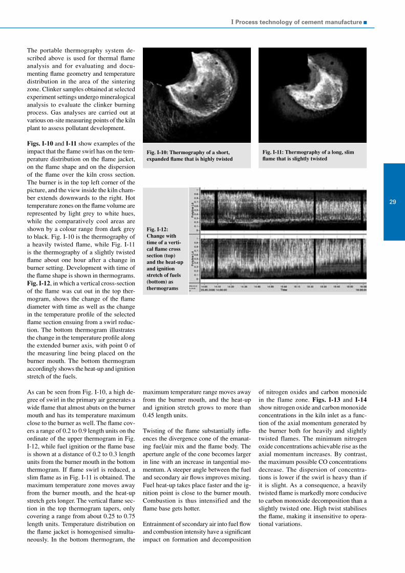
I Process technology of cement manufacture
29
The portable thermography system de-scribed above is used for thermal flame analysis and for evaluating and docu-menting flame geometry and temperature distribution in the area of the sintering zone. Clinker samples obtained at selected experiment settings undergo mineralogical analysis to evaluate the clinker burning process. Gas analyses are carried out at various on-site measuring points of the kiln plant to assess pollutant development.
Figs. I-10 and I-11 show examples of the impact that the flame swirl has on the tem-perature distribution on the flame jacket, on the flame shape and on the dispersion of the flame over the kiln cross section. The burner is in the top left corner of the picture, and the view inside the kiln cham-ber extends downwards to the right. Hot temperature zones on the flame volume are represented by light grey to white hues, while the comparatively cool areas are shown by a colour range from dark grey to black. Fig. I-10 is the thermography of a heavily twisted flame, while Fig. I-11 is the thermography of a slightly twisted flame about one hour after a change in burner setting. Development with time of the flame shape is shown in thermograms. Fig. I-12, in which a vertical cross-section of the flame was cut out in the top ther-mogram, shows the change of the flame diameter with time as well as the change in the temperature profile of the selected flame section ensuing from a swirl reduc-tion. The bottom thermogram illustrates the change in the temperature profile along the extended burner axis, with point 0 of the measuring line being placed on the burner mouth. The bottom thermogram accordingly shows the heat-up and ignition stretch of the fuels.
As can be seen from Fig. I-10, a high de-gree of swirl in the primary air generates a wide flame that almost abuts on the burner mouth and has its temperature maximum close to the burner as well. The flame cov-ers a range of 0.2 to 0.9 length units on the ordinate of the upper thermogram in Fig. I-12, while fuel ignition or the flame base is shown at a distance of 0.2 to 0.3 length units from the burner mouth in the bottom thermogram. If flame swirl is reduced, a slim flame as in Fig. I-11 is obtained. The maximum temperature zone moves away from the burner mouth, and the heat-up stretch gets longer. The vertical flame sec-tion in the top thermogram tapers, only covering a range from about 0.25 to 0.75 length units. Temperature distribution on the flame jacket is homogenised simulta-neously. In the bottom thermogram, the
Fig. I-10: Thermography of a short,expanded flame that is highly twisted
Fig. I-11: Thermography of a long, slim flame that is slightly twisted
Fig. I-12: Change with time of a verti-cal flame cross section (top) and the heat-up and ignition stretch of fuels (bottom) as thermograms
maximum temperature range moves away from the burner mouth, and the heat-up and ignition stretch grows to more than 0.45 length units.
Twisting of the flame substantially influ-ences the divergence cone of the emanat-ing fuel/air mix and the flame body. The aperture angle of the cone becomes larger in line with an increase in tangential mo-mentum. A steeper angle between the fuel and secondary air flows improves mixing. Fuel heat-up takes place faster and the ig-nition point is close to the burner mouth. Combustion is thus intensified and the flame base gets hotter.
Entrainment of secondary air into fuel flow and combustion intensity have a significant impact on formation and decomposition
of nitrogen oxides and carbon monoxide in the flame zone. Figs. I-13 and I-14 show nitrogen oxide and carbon monoxide concentrations in the kiln inlet as a func-tion of the axial momentum generated by the burner both for heavily and slightly twisted flames. The minimum nitrogen oxide concentrations achievable rise as the axial momentum increases. By contrast, the maximum possible CO concentrations decrease. The dispersion of concentra-tions is lower if the swirl is heavy than if it is slight. As a consequence, a heavily twisted flame is markedly more conducive to carbon monoxide decomposition than a slightly twisted one. High twist stabilises the flame, making it insensitive to opera-tional variations.
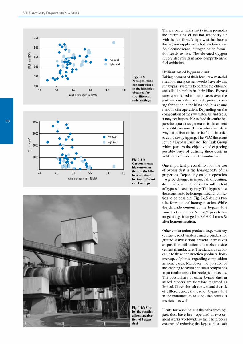
VDZ Activity Report 2005 – 2007
30
The reason for this is that twisting promotes the intermixing of the hot secondary air with the fuel flow. A high twist thus boosts the oxygen supply in the hot reaction zone. As a consequence, nitrogen oxide forma-tion tends to rise. The elevated oxygen supply also results in more comprehensive fuel oxidation.
Utilisation of bypass dustTaking account of their local raw material situation, many cement works have always run bypass systems to control the chlorine and alkali supplies in their kilns. Bypass rates were raised in many cases over the past years in order to reliably prevent coat-ing formation in the kilns and thus ensure smooth kiln operation. Depending on the composition of the raw materials and fuels, it may not be possible to feed the entire by-pass dust quantities generated to the cement for quality reasons. This is why alternative ways of utilisation had to be found in order to avoid costly tipping. The VDZ therefore set up a Bypass Dust Ad Hoc Task Group which pursues the objective of exploring possible ways of utilising these dusts in fields other than cement manufacture.
One important precondition for the use of bypass dust is the homogeneity of its properties. Depending on kiln operation – e.g. by changes in input, fall of coating, differing flow conditions –, the salt content of bypass dusts may vary. The bypass dust therefore has to be homogenised for utilisa-tion to be possible. Fig. I-15 depicts two silos for rotational homogenisation. While the chloride content of the bypass dust varied between 1 and 5 mass % prior to ho-mogenising, it ranged at 3.6 ± 0.1 mass % after homogenisation.
Other construction products (e.g. masonry cements, road binders, mixed binders for ground stabilisation) present themselves as possible utilisation channels outside cement manufacture. The standards appli-cable to these construction products, how-ever, specify limits regarding composition in some cases. Moreover, the question of the leaching behaviour of alkali compounds in particular arises for ecological reasons. The possibilities of using bypass dust in mixed binders are therefore regarded as limited. Given the salt content and the risk of efflorescence, the use of bypass dust in the manufacture of sand-lime bricks is restricted as well.
Plants for washing out the salts from by-pass dust have been operated at two ce-ment works worldwide so far. The process consists of reducing the bypass dust (salt
Fig. I-14:Carbon monox-ide concentra-tions in the kiln inlet obtained for two different swirl settings
Fig. I-13:Nitrogen oxide concentrations in the kiln inlet obtained for two different swirl settings
Fig. I-15: Silos for the rotation-al homogenisa-tion of bypass dust
4.0
1 750
1 500
1 250
1 000
750
500
NOx i
n m
g NO
/m3
4.5 5.0 5.5 6.0 6.5
Axial momentum in N/MW
low swirlhigh swirl
4 000
3 000
2 000
1 000
0
Axial momentum in N/MW
low swirl
high swirl
CO in
mg/
m3
4.0 4.5 5.0 5.5 6.0 6.5

I Process technology of cement manufacture
31
content up to 50 mass %) to slurry by water and dehydrating it in filter presses. In this way, most of the salt contained is washed out, and the filter cake can be fed to the kiln again. The saliferous water has to be neu-tralised, which may involve precipitating and filtering out the organic constituents it contains in some cases. For cost reasons, this method has so far only been applica-ble at sites where saliferous water can be discharged in an environmentally compat-ible fashion.
The Research Institute investigated possi-ble ways of utilising bypass dust in glass manufacture (cf. Chapter III). The alkalis contained in bypass dusts render them an interesting raw material substitute in glass manufacture. The sulphates and chlorides contained, by contrast, may have an ad-verse effect on alkali volatility and melting viscosity, resulting in seed formation and in the corrosion of the smelting furnaces, respectively. Initial melting trials were very promising. Long-term experience with the use of bypass dust in glass production on an industrial scale is, however, not yet available.
Modelling of the clinker burning processThe Research Institute of the Cement Industry is developing a plant technol-ogy process simulator for calculating the clinker burning process. The model now describes the entire clinker burning process from the input of raw materials and fuels up to the discharge of the clinker from the cooler and of the kiln exhaust gas from the stack. The main focus is placed on the plant components in the inner system boundaries. The model consists of separate models for the cyclones of the preheater, the calciner, the bypass, the rotary kiln and the grate or satellite cooler, respectively. It further covers the outer system bounda-ries, comprising models of the evaporative cooler, the raw mill, the pre-separator and the dust collector. These modules are con-nected to each other mathematically and allow determination of the steady state of the entire clinker production plant. The modular structure thus permits the indi-vidual and flexible simulation of different plants with regard to the parameters of the individual plant components, the plant ar-rangement, the modes of operation, and the raw materials and fuels.
The basis from which all these calcula-tion studies proceed is the reference state of a plant, which is developed in co- operation with plant operators on the ba-sis of measurement results and operating
experiences and is to reflect the respective current standard operation of the plant as precisely as possible. Taking this state as a basis, it is possible to change operational settings, vary the type and quantity of fu-els, and modify entire plant sections. The calculations based on parameter variations supply extensive data on the relevant pro-cess variables for all plant sections. Thus, mass and volume flows as well as their composition, gas and solids temperatures, losses of heat and the specific energy consumption for clinker burning are de-termined, for example. Evaluation of the data calculated in terms of quality and quantity is effected through a comparison with the reference scenario, the process technology plausibility of the data always being subjected to critical scrutiny. The mathematical model is based on generally acknowledged basic principles of process engineering, heat transfer and material science, as well as the process know-how gained from numerous kiln and laboratory trials carried out by the Research Institute. The verifiability of the calculated results was repeatedly checked and improved by doing calculations for different kiln plants and comparing the results with the meas-urement values. Limestone calcination, clinker phase formation and the firing of fuels constitute the most important chemi-cal reactions, which are calculated in detail for each section of the kiln plant. Since the fuel ashes are taken into consideration as well, the effects of a change in fuel type can thus be calculated both with regard to the quantity and composition of the exhaust air (O
2, CO
2, H
2O, N
2) and with
regard to the clinker phases.
The model is primarily applied to explore questions regarding energy and materials, particular focus being placed on inter- actions within the process. Thus, the model was already used to select suitable alterna-tive fuels and to evaluate the possible input quantities at a kiln plant. Moreover, the simulation software served to calculate and optimise the operation of a gas bypass at the kiln inlet to contain recirculating chlorine systems between the kiln and the preheater. In addition to these studies on alternative fuel use and the relieving of recirculating material systems via a gas bypass, it is possible to carry out parameter variations at fairly low cost and effort. In this way, it becomes possible to make statements on the effects of plant reconfigurations, such as the installation of additional or more effective cyclones in the preheater, and of modifications in plant operation, such as temperature reductions in the sinter-ing zone.
The model was thus employed to quantify the effects of different influencing vari-ables on the fuel energy consumption of the clinker burning process (see also Chapter I, Energy consumption). In addition to variations in raw material moisture and cyclone stages, different fuels which have divergent properties, and varying bypass rates, it was also plant size and clinker quality that was taken into account. The effects on specific energy consumption that were calculated are summarised in Table I-3. Transferred to practical application, the steady operating state calculated using the model corresponds to operation during an optimised short-term performance test. The hard coal-fired reference plant, which was defined in accordance with the previous BREF (Best Available Techniques Refer-ence Document), attains a clinker-specific fuel energy consumption of just over 3 000 kJ/kg clinker. As operational variations are bound to occur during practical operation, this consumption increases to approx. 3 180 to 3 340 kJ/kg clinker. A reduction in the lime standard, larger plant capacity and the use of an additional cyclone stage re-sulted in fuel energy consumption that was lower than that of the reference scenario. By contrast, the use of a gas bypass to reduce recirculating material systems, the utilisation of fuels which have unfavour-able properties, as well as plants with low production capacity, moister raw materials or fewer cyclone stages, respectively, led to higher thermal requirement.
A further simulation study was concerned with the possibility of utilising concrete crusher sand as a raw material substitute that is already decarbonated to a certain degree (see also Chapter VI, Sustainable building with concrete – utilisation of concrete crusher sand). Apart from the high-grade utilisation of this mineral ma-terial in the building industry cycle, its use in the clinker burning process helps preserve valuable natural raw material and fuel resources and reduces emissions of the climatically relevant CO
2 gas. The calcu-
lations performed to date yielded possible raw material savings of up to 10 mass % of the original raw material depending on the respective site. Given the high silicon proportion of the crusher sand, the materi-als appropriate for substitution are chiefly sand and, to a lesser extent, also calcium agents. As can be seen from Fig. I-16, it is further possible to lower thermal energy consumption by up to 3% or 80 kJ/kg clinker, and CO
2 emissions by more than
20 kg CO2/t clinker. One criterion that was
borne in mind during the studies was to keep within acceptable limits the changes

VDZ Activity Report 2005 – 2007
32
Table I-3: Specific energy consumption of different scenarios in comparison to the referencestate and on annual average
Specific fuel energy requirement in kJ/kg clinker
Performance testDifference to the
reference scenarioAnnual average
Reference 3 026 3 180 to 3 340
Lime standard 94 2 982 -44 3 140 to 3 300
Kiln capacity 1 500 t/d 3 239 213 3 400 to 3 560
Kiln capacity 5 000 t/d 2 922 -104 3 080 to 3 240
3 cyclone stages 3 272 246 3 430 to 3 590
4 cyclone stages 3 115 89 3 260 to 3 420
6 cyclone stages 2 965 -61 3 120 to 3 280
5% bypass rate 3 054 28 3 210 to 3 370
10% bypass rate 3 080 54 3 240 to 3 400
15% bypass rate 3 106 80 3 270 to 3 430
100% lignite 3 122 96 3 280 to 3 440
40% substitution PL 3 122 96 3 280 to 3 440
RG 3 153 127 3 320 to 3 480
70% substitution PL 3 235 209 3 390 to 3 550
RG 3 310 284 3 470 to 3 630
100% substitution PL 3 355 329 3 510 to 3 670
RG 3 469 443 3 630 to 3 790
PL: constant outputRG: constant raw gas volume flow
that process technology and plant opera-tion variables as well as clinker quality in particular underwent in comparison to the reference scenario.
The aspect that is often particularly inter-esting about a shift in fuel type or the use of substitute raw materials is the associated change in chlorine input into the plant. Together with sulphur and alkalis, chlo-rine forms recirculating systems between the rotary kiln and the bottom stages of the preheater or the calciner, respectively. These substances and their compounds evaporate in the kiln and are carried into the preheater together with the gas flow. At low temperatures, they condense there on the meal and the dust as well as the plant walls, on which coatings are formed. Apart from the higher risk of operational malfunctions due to coating formation, the evaporation and condensation lead to heat being trans-mitted from the kiln into the preheater. This results in higher energy input via the main firing unit and restricts the quantity of fuel that can be fed to the kiln inlet or calciner firing units. A simulation study investigated the operation of a modern rotary kiln run exclusively on pulverised lignite in comparison with its operation on the basis of different alternative fuels. As a consequence of these shifts in fuel types, chlorine input into the process increased more than 10-fold, from approx. 90 to more than 900 mg/kg clinker. This resulted in a considerable rise in the chlorine contents of the hot meals. The content in the kiln inlet meal swelled from approx. 0.6 mass % Cl− to substantially above 6 mass %, i.e. contents that neither operation under prac-tical conditions nor the model can keep in check. Calculations therefore included a gas bypass at the kiln inlet. This relief of the recirculating system resulted in hot meal contents below 1.5 mass % Cl− at bypass rates of less than 5% relative to the kiln inlet volume flow. As a consequence of the fuel shift and bypass operation, fuel energy consumption increased by up to 150 kJ/kg clinker, which was primarily attributable to higher raw gas volume flows, higher tem-peratures in the kiln inlet and the preheater, elevated loss of heat through shell of kiln, and the energy flow of the bypass gas. The proportion of total firing heat capacity that the main firing unit accounted for had to be increased from approx. 44% to up to 66%. Accordingly, energy input via the calciner had to be reduced from approx. 56% to down to 34%.
Fig. I-16:Reduction po-tentials due to the use of dif-ferent concrete crusher sands
100
80
60
40
20
01 2 3 1L 4 51F
Concrete crusher sands under review
Redu
ction
in en
ergy
requ
irem
ent i
n kJ
/kg cl
CO2 r
educ
tion
in kg
CO 2
/t cl
50
40
30
20
10
0
primary raw material saving in %:
reduction in energy requirement reduction in CO2 emissions
4.7 4.8
5.75.7
7.3
8.1
9.6
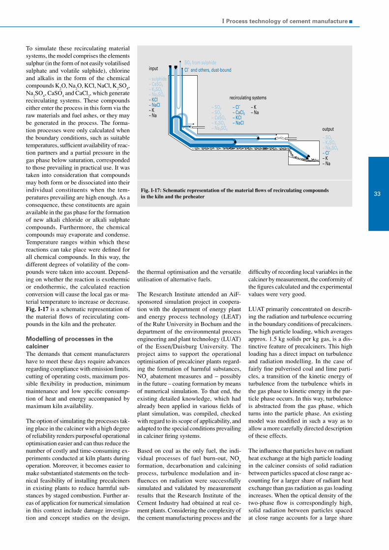
I Process technology of cement manufacture
33
To simulate these recirculating material systems, the model comprises the elements sulphur (in the form of not easily volatilised sulphate and volatile sulphide), chlorine and alkalis in the form of the chemical compounds K
2O, Na
2O, KCl, NaCl, K
2SO
4,
Na2SO
4, CaSO
4 and CaCl
2, which generate
recirculating systems. These compounds either enter the process in this form via the raw materials and fuel ashes, or they may be generated in the process. The forma-tion processes were only calculated when the boundary conditions, such as suitable temperatures, sufficient availability of reac-tion partners and a partial pressure in the gas phase below saturation, corresponded to those prevailing in practical use. It was taken into consideration that compounds may both form or be dissociated into their individual constituents when the tem-peratures prevailing are high enough. As a consequence, these constituents are again available in the gas phase for the formation of new alkali chloride or alkali sulphate compounds. Furthermore, the chemical compounds may evaporate and condense. Temperature ranges within which these reactions can take place were defined for all chemical compounds. In this way, the different degrees of volatility of the com-pounds were taken into account. Depend-ing on whether the reaction is exothermic or endothermic, the calculated reaction conversion will cause the local gas or ma-terial temperature to increase or decrease. Fig. I-17 is a schematic representation of the material flows of recirculating com-pounds in the kiln and the preheater.
Modelling of processes in the calcinerThe demands that cement manufacturers have to meet these days require advances regarding compliance with emission limits, cutting of operating costs, maximum pos-sible flexibility in production, minimum maintenance and low specific consump-tion of heat and energy accompanied by maximum kiln availability.
The option of simulating the processes tak-ing place in the calciner with a high degree of reliability renders purposeful operational optimisation easier and can thus reduce the number of costly and time-consuming ex-periments conducted at kiln plants during operation. Moreover, it becomes easier to make substantiated statements on the tech-nical feasibility of installing precalciners in existing plants to reduce harmful sub- stances by staged combustion. Further ar-eas of application for numerical simulation in this context include damage investiga-tion and concept studies on the design,
the thermal optimisation and the versatile utilisation of alternative fuels.
The Research Institute attended an AiF-sponsored simulation project in coopera-tion with the department of energy plant and energy process technology (LEAT) of the Ruhr University in Bochum and the department of the environmental process engineering and plant technology (LUAT) of the Essen/Duisburg University. The project aims to support the operational optimisation of precalciner plants regard-ing the formation of harmful substances, NO
x abatement measures and – possibly
in the future – coating formation by means of numerical simulation. To that end, the existing detailed knowledge, which had already been applied in various fields of plant simulation, was compiled, checked with regard to its scope of applicability, and adapted to the special conditions prevailing in calciner firing systems.
Based on coal as the only fuel, the indi-vidual processes of fuel burn-out, NO
x
formation, decarbonation and calcining process, turbulence modulation and in-fluences on radiation were successfully simulated and validated by measurement results that the Research Institute of the Cement Industry had obtained at real ce-ment plants. Considering the complexity of the cement manufacturing process and the
Fig. I-17: Schematic representation of the material flows of recirculating compoundsin the kiln and the preheater
difficulty of recording local variables in the calciner by measurement, the conformity of the figures calculated and the experimental values were very good.
LUAT primarily concentrated on describ-ing the radiation and turbulence occurring in the boundary conditions of precalciners. The high particle loading, which averages approx. 1.5 kg solids per kg gas, is a dis-tinctive feature of precalciners. This high loading has a direct impact on turbulence and radiation modelling. In the case of fairly fine pulverised coal and lime parti-cles, a transition of the kinetic energy of turbulence from the turbulence whirls in the gas phase to kinetic energy in the par-ticle phase occurs. In this way, turbulence is abstracted from the gas phase, which turns into the particle phase. An existing model was modified in such a way as to allow a more carefully directed description of these effects.
The influence that particles have on radiant heat exchange at the high particle loading in the calciner consists of solid radiation between particles spaced at close range ac-counting for a larger share of radiant heat exchange than gas radiation as gas loading increases. When the optical density of the two-phase flow is correspondingly high, solid radiation between particles spaced at close range accounts for a large share
input
– sulphide– CaSO4– K2SO4– Na2SO4– KCI– NaCl– K– Na
SO2 from sulphideCl- and others, dust-bound
recirculating systems
– SO2– SO3– CaSO4– K2SO4– Na2SO4
– Cl-– CaCl2– KCl– NaCl
– K– Na
output
– SO3– K2SO4– Na2SO4– Cl-– K– Na

VDZ Activity Report 2005 – 2007
34
of radiant heat exchange in the flow, while gas radiation becomes less relevant. In addition to that, dispersion effects occur who’s intensity and directional orientation depends on the size, material, shape and surface of the individual particles. To take these effects into account, a model origi-nally developed in power plant technology was adapted to the conditions prevailing in the calciner and further advanced. The test results that the Research Institute obtained during operational measurements at KHD and Polysius calciners served to adapt and validate the model elements. These results were furnished by the AiF research project 12699 N.
LEAT implemented and successfully en-hanced the models covering the calcination and sulphatisation of meal particles, fuel burn-out and NO
x formation.
The models simulating the calcining and sulphatisation reaction were extended to also include the transient progress of limestone meal porosity and the specific inner surface available for the reactions now. This allows a more precise simula-tion of the course of the calcining reaction. Moreover, the formation of a sulphate layer of low porosity due to the sulphatisation reaction is simulated as well. As a result, the model also reproduces the increase in the pore resistance to diffusion and the associated decrease in the velocity of the calcining reaction.
Various models for describing NOx for-
mation and reduction in the calciner were investigated as well. The way of looking at the problem can be subdivided into three parts: the release of fuel-related nitrogen, the gas phase reactions of the N com-
pounds, and the influence of heterogene-ous reactions on the meal particle surfaces. Detailed pyrolysis models comprising a prior step to determine the distribution of fuel-related nitrogen to volatiles and coke as well as the release in the form of HCN and NH
3 during pyrolysis were applied for
the release of fuel-related nitrogen from coal. To cover the gas phase reactions, sev-eral global kinetic NO
x models were tested
and compared with experimental results obtained by laboratory trials. Proceeding from this basis, a global kinetic model describing both the formation of NO
x and
its reduction under calciner conditions was integrated in the CFD programme. This model was again validated by means of the Research Institute’s above-men-tioned measurement results. Based on the example of one kiln, Figs. I-18 to I-21 show the temperatures calculated and
Fig. I-18: Comparison of measured and calculated temperatures Fig. I-19: Comparison of measured and calculated CO2concentrations
Fig. I-20: Comparison of measured and calculated O2concentrations
Fig. I-21: Comparison of measured and calculated NOconcentrations
1 200
1 000
800
600
400
200
0
Tem
pera
ture
in°C
Inlet upstream pre-calciner firing 1
upstream topair supply
downstreamtop air supply
simulationmeasurement
35
30
25
20
15
10
5
0
CO2 i
n vo
l.-%
Inlet
simulationmeasurement
upstream pre-calciner firing 1
upstream topair supply
downstreamtop air supply
6
5
4
3
2
1
0
O 2 in
vol.-
%
Inlet
simulationmeasurement
upstream pre-calciner firing 1
upstream topair supply
downstreamtop air supply
600
500
400
300
200
100
0
NO in
ppm
Inlet
simulationmeasurement
upstream pre-calciner firing 1
upstream topair supply
downstreamtop air supply

I Process technology of cement manufacture
35
the concentrations of CO2, O
2 and NO in
comparison to the values that the Research Institute measured as part of the industrial trials. The dots represent mean values. The values calculated and the curves of the data measured by the on-site measuring devices at the calciner inlet, upstream of precalciner burning unit, upstream of the top air supply (“TA”) tallied well in terms of quality and quantity. The deviations (especially regarding NO) in the area of the reducing zone upstream of the over-fire air were attributable to inaccuracies still affecting the reaction system. These form the subject of continuative research. On the whole, simulation permits correct reproduction of the process behaviour and highlights the influence of underlying con-ditions on operation.
The influence of the heterogeneous reac-tions taking place on the raw meal surface were studied as well and included in the calculations through a sub-model devel-oped for the simulation of fluidised bed combustion.
The AiF project thus provided the basis for extending the findings on the CFD simula-tion of precalciners. It further allowed cal-ciner-specific sub-models (calcination and sulphatisation process, turbulence modula-tion, radiant heat exchange, coal burn-out, NO
x formation) to be developed, integrated
into the CFD codes, and validated.
Proceeding from the results of the AiF project, a further research project applied for is aimed at applying CFD methods to investigate the substitution of alternative fuels for coal now. The objective pursued is to extend the possible ways of utilising alternative fuels in precalcining systems and to thus make an important contribu-tion to maintaining the competitiveness of the German cement industry. Moreover, operators of precalcining systems are to be put in a position to utilise alternative fuels for purposeful NO
x abatement (e.g. in
staged combustion) and to reduce the costs incurred by secondary reduction measures in this way.
Refractory materialsThe know-how on the use of refractory ma-terials available to cement works decreased continually over the past years. This is why the “Refractory materials” working group was set up and given the task to summa-rise the current state of knowledge on this subject in a code of practice.
To ensure high operational reliability of the kilns and plan kiln repairs, informa-
tion on the condition of the refractory material is indispensable. In this context, a distinction has to be made between assess-ing the refractory condition from outside during regular operation and diagnosing its condition from within by walk-through inspection. Routine control of the kiln shell temperature by recording infrared radia-tion is a measure suited for surveying the condition from outside. Highly efficient automated recording and evaluation sys-tems serving this purpose are available in the market. Evaluation of the maximum, mean and minimum kiln shell temperature allows statements to be made on lining and coating conditions. Further development can be estimated on the basis of the rate of temperature change.
During a kiln standstill, the thickness of the remaining bricks can be determined either by non-destructive testing or by drilling or breaking out windows. Experience shows that non-destructive measuring equipment does not furnish reliable measuring signals. Drilling with a rock drill (8 to 10 mm) al-lows determination of the precise thickness
of the remaining bricks, but damage to the bricks (cracking, alkali infiltration) cannot be detected. At critical points, the condition of the refractory material should therefore be examined by means of core drilling or breaking out windows. The drill cores and bare bricks thus obtained allow the condi-tion to be assessed exactly. This method does, however, not allow the brickwork to be closed again durably when the remain-ing brick height is low. The service life of refractory material depends on a number of influencing factors, which chiefly include the mechanical, thermal and chemical stresses prevailing at the site. Excessive mechanical stress can result in pop-outs, detachment (Fig. I-22), concentric crack-ing, spiral torsion of individual brick tyres, breakouts in the tyre area, or axial grooves. This is usually attributable to the quality of the lining (executed too loosely or too tightly) or to excessive kiln out-of-roundness. Thermal overheating due to the absence of coating or direct contact with the flame can lead to melting symptoms, melted mass infiltration or recrystallisa-tion, which in turn attenuates the brick
Fig. I-22:Lining detached due to insuf-ficient clearance between expan-sion joints
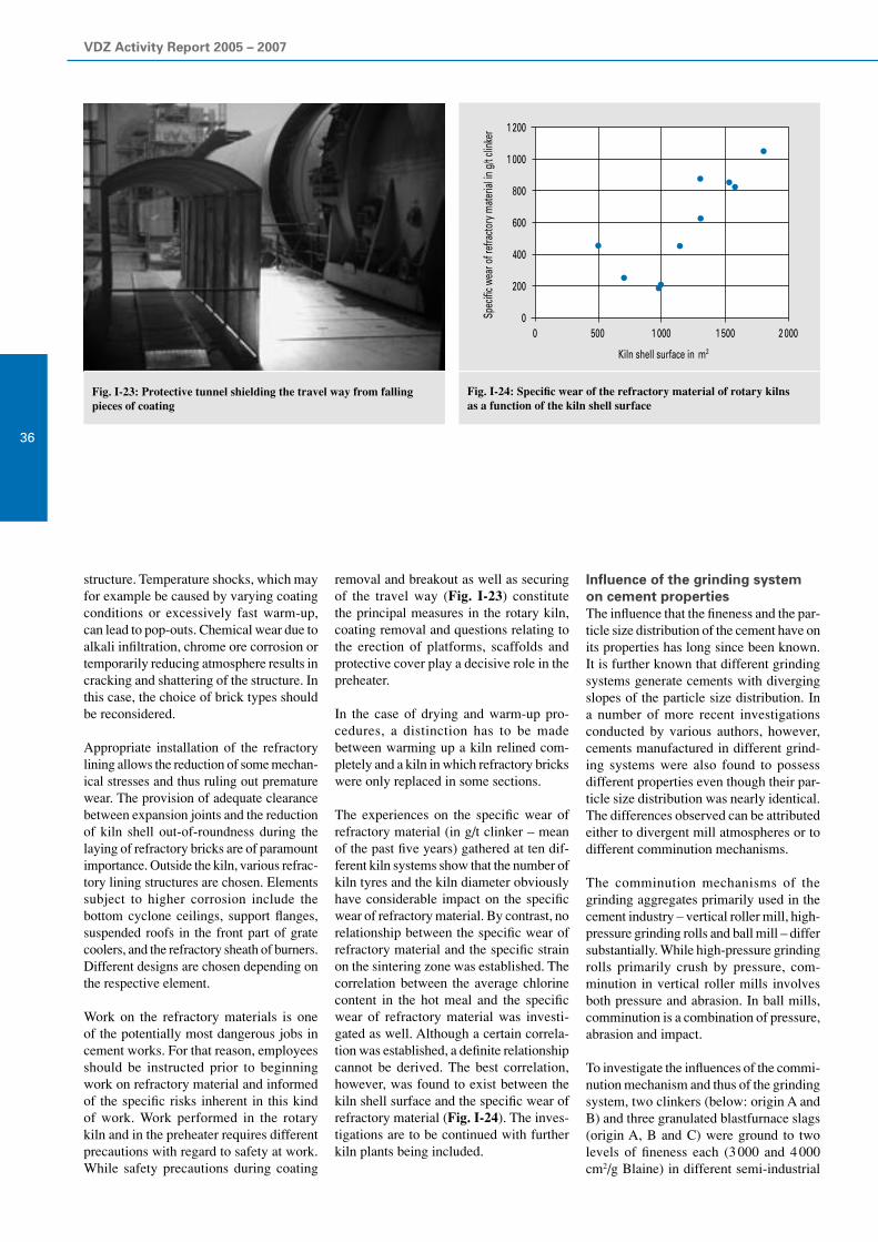
VDZ Activity Report 2005 – 2007
36
structure. Temperature shocks, which may for example be caused by varying coating conditions or excessively fast warm-up, can lead to pop-outs. Chemical wear due to alkali infiltration, chrome ore corrosion or temporarily reducing atmosphere results in cracking and shattering of the structure. In this case, the choice of brick types should be reconsidered.
Appropriate installation of the refractory lining allows the reduction of some mechan-ical stresses and thus ruling out premature wear. The provision of adequate clearance between expansion joints and the reduction of kiln shell out-of-roundness during the laying of refractory bricks are of paramount importance. Outside the kiln, various refrac-tory lining structures are chosen. Elements subject to higher corrosion include the bottom cyclone ceilings, support flanges, suspended roofs in the front part of grate coolers, and the refractory sheath of burners. Different designs are chosen depending on the respective element.
Work on the refractory materials is one of the potentially most dangerous jobs in cement works. For that reason, employees should be instructed prior to beginning work on refractory material and informed of the specific risks inherent in this kind of work. Work performed in the rotary kiln and in the preheater requires different precautions with regard to safety at work. While safety precautions during coating
removal and breakout as well as securing of the travel way (Fig. I-23) constitute the principal measures in the rotary kiln, coating removal and questions relating to the erection of platforms, scaffolds and protective cover play a decisive role in the preheater.
In the case of drying and warm-up pro- cedures, a distinction has to be made between warming up a kiln relined com-pletely and a kiln in which refractory bricks were only replaced in some sections.
The experiences on the specific wear of refractory material (in g/t clinker – mean of the past five years) gathered at ten dif-ferent kiln systems show that the number of kiln tyres and the kiln diameter obviously have considerable impact on the specific wear of refractory material. By contrast, no relationship between the specific wear of refractory material and the specific strain on the sintering zone was established. The correlation between the average chlorine content in the hot meal and the specific wear of refractory material was investi-gated as well. Although a certain correla-tion was established, a definite relationship cannot be derived. The best correlation, however, was found to exist between the kiln shell surface and the specific wear of refractory material (Fig. I-24). The inves-tigations are to be continued with further kiln plants being included.
Fig. I-23: Protective tunnel shielding the travel way from falling pieces of coating
Influence of the grinding system on cement propertiesThe influence that the fineness and the par-ticle size distribution of the cement have on its properties has long since been known. It is further known that different grinding systems generate cements with diverging slopes of the particle size distribution. In a number of more recent investigations conducted by various authors, however, cements manufactured in different grind-ing systems were also found to possess different properties even though their par-ticle size distribution was nearly identical. The differences observed can be attributed either to divergent mill atmospheres or to different comminution mechanisms.
The comminution mechanisms of the grinding aggregates primarily used in the cement industry – vertical roller mill, high-pressure grinding rolls and ball mill – differ substantially. While high-pressure grinding rolls primarily crush by pressure, com-minution in vertical roller mills involves both pressure and abrasion. In ball mills, comminution is a combination of pressure, abrasion and impact.
To investigate the influences of the commi-nution mechanism and thus of the grinding system, two clinkers (below: origin A and B) and three granulated blastfurnace slags (origin A, B and C) were ground to two levels of fineness each (3 000 and 4 000 cm2/g Blaine) in different semi-industrial
Fig. I-24: Specific wear of the refractory material of rotary kilnsas a function of the kiln shell surface
Spec
ific w
ear o
f ref
racto
ry m
ater
ial in
g/t
clink
er
1 200
1 000
800
600
400
200
00 500 1 000 1 500 2 000
Kiln shell surface in m2

I Process technology of cement manufacture
37
grinding plants as part of the AiF research project 14025N. The objective pursued was to generate comparable particle size distributions for meals of the same origin and strength level. Afterwards, cements were made from the meals and tested for properties such as strength, water demand, setting behaviour and particle shape.
The investigations were carried out in semi-commercial plants in cooperation with Gebr. Pfeiffer AG and KHD Humboldt Wedag. The semi-industrial vertical roller mill of Gebr. Pfeiffer AG (Fig. I-25) has a grinding disc diameter of 35 cm and an integrated rod cage rotor classifier. During the trials, mill throughput ranged between 150 and 210 kg/h. The throughput of the semi-industrial high-pressure grinding rolls of KHD Humboldt Wedag (Fig. I-26) ranged between 300 and 700 kg/h depend-ing on the material and its fineness. This grinding system consists of a roller press, a VSK separator and an eyebolt that conveys the scabs generated to the classifier feed-ing unit. The closed-circuit grinding plant comprising a ball mill and a classifier that was employed is located at the Research Institute (Fig. I-27). For the ball mill to produce particle size distributions that were comparable to those of the other grinding systems, the mass flows circulating during its operation had to be high. Accordingly, circulating mass flows of up to 400 kg/h were set to achieve a throughput between 13 and 25 kg/h.
Fig. I-28 shows the particle size distri-butions of the clinker meals of origin B ground to a Blaine fineness of 3 000 cm2/g on the high-pressure grinding rolls (GWM), the vertical roller mill (VWM)
and the ball mill (KM). As can be seen, it was possible to produce nearly identical particle size distributions by taking cor-responding grinding technology measures (e.g. unusually high pressure applied in the GWM and the VWM or high circulation rates in the KM). It was further possible to produce meals of nearly identical particle size distribution from the other starting materials and the other fineness level, re-spectively, in nearly all grinding trials by choosing appropriate settings of the plant parameters.
To investigate their properties, a total SO3
content of 3 % was set in the clinker meals by adding anhydrite and hemihydrate. First of all, water demand at standard stiffness and at the saturation point as well as set-ting behaviour were checked. Within a group made up of identical starting ma- terials and identical fineness, no significant differences between the various grinding systems applied were observed.
Strength testing was carried out on mortar prisms in accordance with EN 196. All tests were repeated three times to make sure the results were correct. With both clinkers and both levels of fineness, the meals produced on the high-pressure grinding rolls pos-sessed higher compressive strength after two days than the corresponding clinker meals ground on the other grinding sys-tems. By contrast, the strength values of the clinker meals produced on the vertical roller mill and the ball mill were compa-rable. After 7 and 28 days, respectively, however, the strength values of the clinker meals obtained from the high-pressure grinding rolls no longer differed from those of the two other grinding systems.
Fig. I-25: Semi-industrial vertical roller mill of Gebr. Pfeiffer AG
Fig. I-26: Semi-industrial high-pressure grinding rolls of KHD Humboldt Wedag
Fig. I-27: Semi-industrial ball mill of the Research Institute Fig. I-28: Particle size distributions of clinker B at a fineness of3 000 cm2/g Blaine
Clinker B (3000)
Particle size in µm0,1
100
80
60
40
20
0
Perc
enta
ge p
assin
g in
%
10 1001
5
4
3
2
1
0
vertical roller millhigh-pressure grinding rollsball mill
Dens
ity d
istrib
utio
n in
%
density distributionpercentage passing

VDZ Activity Report 2005 – 2007
38
Fig. I-29 depicts the compressive strengths based on the example of clinker B with a fineness of 3 000 cm2/g. Moreover, concrete investigations were conducted to confirm the results obtained by mortar testing. Ac-cording to these trials, however, the three grinding systems did not produce any dif-ferences in compressive strength after two days. This is probably due to the fact that, at 330 kg cement/m3 concrete, the cement proportion in concrete tests is considerably lower than in mortar testing.
After the ground blastfurnace slags had been mixed with two different CEM I ce-ments (at a blastfurnace slag/CEM I cement ratio of 70% to 30%) and sulphate agents, their strength properties were examined as well. Regardless of the CEM I cement intermixed, significant relationships be-tween the grinding system applied and the strength level attained were established for none of the three blastfurnace slags.
The grain shapes of the meal particles generated were investigated by means of two different analysis instruments, namely the grain shape analysers produced by the Malvern and Occhio companies. Grain shape is measured by producing spread samples and then recording and evaluat-ing 25 000 individual particles each by a high-resolution camera. The grain shape parameters for individual grain fractions were determined as means of all particles contained in the grain class and represented above the mean grain size of the fraction. The results of the mean roundness distribu-tion of clinker B 3 000 are shown by way of example in Fig. I-30. The meals produced by the different grinding systems exhibited comparable grain shape parameters for the particles of all grain classes. The results obtained by measuring the grain shape of the meals of different strength level or different origin, respectively, ground on the various grinding systems mentioned above were comparable as well. The other measuring instrument used did not yield any significant differences between the grinding systems with regard to the grain shape generated either.
The meals produced further underwent various chemico-mineralogical investiga-tions. The clinker meals were fractionated by screening and by means of a high-per-formance laboratory classifier, and the clinker phase contents of the individual fractions were determined by X-ray dif-
Fig. I-30: Roundness dis-tribution of the clinker meals of fineness 3 000 and origin B
Fig. I-29: Compressive strengths of the B 3 000 clinkers
Fig. I-31: Phase contents of the< 20 μm fraction of the B 3000 clinkers
70
60
50
40
30
20
10
0
2 days 7 days 28 days
High-pressure grinding rolls Vertical roller mill Ball mill
Com
pres
sive s
treng
th in
N/m
m2
80
70
60
50
40
30
20
10
0C3S C2S
ball millhigh-pressure grinding rollsvertical roller mill
Cont
ents
in %

I Process technology of cement manufacture
39
fractometry in combination with Rietveld refinement. This revealed that the clinker meals produced on the high-pressure grind-ing rolls had higher C
3S contents in the
< 20 μm fraction than those made by other grinding systems (Fig. I-31). C
3S enrich-
ment in the < 20 μm fraction was observed with both clinkers.
In addition to that, the heat of hydration of the different clinker fractions during the first 72 hours was investigated. The investigation results yielded a definite correlation between particle size and heat loss. The smaller the cement particles are, the larger is their specific surface, and the higher is the heat of hydration. By contrast, the heats of hydration measured for the respective fractions of the clinker meals made by different grinding systems did not diverge significantly.
The blastfurnace slags, too, were frac-tionated by screening and classifying and analysed subsequently. The meal sam-ples were investigated by simultaneous thermal analysis, high-temperature X-ray diffractometry and cathode luminescence microscopy. None of the analysis methods employed yielded any significant discrep-ancies between the ground granulated blastfurnace slags produced by the three different grinding systems.
To sum up, it was found that the grinding system did not have a significant impact on the properties of blastfurnace cements. In Portland cement production, the clinker
meals ground in the high-pressure grinding rolls generated slightly higher compressive strengths in mortar prisms than the clinker meals made in ball mills or vertical roller mills. At later testing dates, however, the strength values obtained from the three grinding systems did not differ signifi-cantly.
Influence of the mill atmosphere on the properties of cements containing blastfurnace slagDepending on production and storage con-ditions, blastfurnace slags have moisture contents ranging between 6 and 12%. To be used in cement manufacture, the blast-furnace slag has to be dried either before or during grinding. The use of kiln exhaust gas or exhaust air from the cooler is convenient for drying purposes at cement works.
A number of investigations conducted at industrial plants to determine the impact of the drying gas on blastfurnace slag grind-ing revealed that, in comparison to the use of exhaust air from the clinker cooler, the utilisation of kiln exhaust gas had adverse effects on blastfurnace slag properties. It was not possible to verify the parameters precisely. The Research Institute therefore investigated the influence of the grinding atmosphere on the properties of cements containing blastfurnace slag.
The investigations consisted of grinding three blastfurnace slags of different reac-tivity and origin in dry ambient air atmos-phere, in CO
2 atmosphere, in ambient air
atmosphere at 6% moisture (relative to the blastfurnace slag) and in CO
2 atmosphere at
6% moisture each. Grinding was performed in a ball mill operated intermittently and provided with electric heating. A tempera-ture of 120 °C was set in all grinding tests. To conduct grinding in CO
2 atmosphere,
pure CO2 was injected into the mill via
existing valves, thus displacing the ambient air contained. For grinding in moist atmos-phere, the mill filled with material was pre-heated, the corresponding water quantity was added shortly before the trial started, and the mill cover was closed again.
In each of the atmospheres described, the blastfurnace slag was first ground to a fine-ness of 4 000 cm2/g Blaine. The particle size distributions of the ground granulated blastfurnace slags obtained are shown in Fig. I-32. In this test series, however, the ground blastfurnace slags generated in moist mill atmosphere turned out to have coarser particle size distributions in spite of identical specific surface. For that reason, grinding time was extended in a further test series in order to grind all the blastfurnace slags to the same particle size distribution in the different mill atmospheres (Fig. I-33). The specific surface areas of the ground blastfurnace slags produced in dry and moist atmosphere differed by approx. 250 cm2/g Blaine.
The water and CO2 contents of the meals
generated were analysed chemically. This revealed that the CO
2 content of the blast-
furnace slags ground in CO2 atmosphere
Fig. I-33: Particle size distributions of the blastfurnace slags with comparable PSD
Fig. I-32: Particle size distributions of the blastfurnace slags with identical specific surface area
Particle size in µm µm
1
100
80
60
40
20
0
Perc
enta
ge p
assin
g in
%
10 100
Particle size in
1
100
80
60
40
20
0
Perc
enta
ge p
assin
g in
%
10 100
ambient airCO2 atmosphere6% moisture6% moisture andCO2 atmosphere
ambient airCO2 atmosphere6% moisture6% moisture andCO2 atmosphere

VDZ Activity Report 2005 – 2007
40
was higher after grinding as well. The CO2
content of the blastfurnace slags ground in moist CO
2 atmosphere was particularly
high. Fig. I-34 depicts the CO2 and water
contents of one blastfurnace slag chosen as an example. Moreover, the ground blastfur-nace slags were fractionated by means of a high-performance laboratory classifier. Then the CO
2 and water contents of the
individual fractions were determined. The fairly fine fractions were found to bind substantially more water and CO
2 than the
coarser fractions.
The ground granulated blastfurnace slags generated (test series with identical particle size distribution) were mixed with a CEM I cement at a ratio of 70% blastfurnace slag and 30% CEM I and tested for compressive
strength after 2, 7 and 28 days to analyse their strength properties.
Using blastfurnace slag A, which was ground to the same particle size distribution in the four different atmospheres described, by way of example, Fig. I-35 shows the compressive strengths after 2, 7 and 28 days. The compressive strengths hardly differed after 2 days. Only the combined atmosphere of water vapour and CO
2 was
found to cause a decline in strength after 2 days. After 7 and 28 days, respectively, however, grinding in dry CO
2 atmosphere
was found to have a significant impact on compressive strength as well. A combina-tion of water vapour and CO
2 atmosphere
reduces strength more markedly.
To study this effect, the meals generated and the fractions made from them were analysed by scanning electron microscopy. Blastfurnace slag particles of identical ori-gin that were ground in ambient air (left) and in moist CO
2 atmosphere are shown
in Fig. I-36 by way of example. Hardly any precipitations or reaction products are discernible on the particle surfaces of the blastfurnace slags ground in ambient air. By contrast, the surfaces of the blastfur-nace slag particles ground in moist CO
2
atmosphere are visibly coated by reaction products. These reaction products were analysed by EDX and identified as a cal-cium carbonate compound.
Summing up, one can state that the grinding atmosphere has an impact on the proper-ties of ground granulated blastfurnace slag. Regardless of the reactivity and origin of the blastfurnace slag, grinding in CO
2 at-
mosphere – and in moist CO2 atmosphere
in particular – has an adverse effect on strength properties. This is due to the more marked fixation of CO
2 and water in the
form of reaction products on the particle surfaces. In measurement using the Blaine method, these reaction products also yield elevated specific surface areas.
Fig. I-34: CO2 and H2O contents of the blastfurnace slags Fig. I-35: Compressive strengths of the blastfurnace cements
Fig. I-36: SEM pictures of blastfurnace slag particles ground in different atmospheres;ambient air on the left, CO2 atmosphere with 6% moisture on the right
1.21.11.00.90.80.70.60..50.40.30.20.10.0
H 2O- an
d CO
2 cont
ent i
n %
Ambientair
CO2atmosphere
Blastfurnaceslag
6%moisture
6% moisture andCO2 atmosphere
Mill atmosphere
CO2H2O
Ambient air CO2 atmosphere 6% moisture 6% moisture andCO2 atmosphere
Mill atmosphere
50454035302520151050
Com
pres
sive s
treng
th in
MPa
7 days2 days 28 days

I Process technology of cement manufacture
41

VDZ Activity Report 2005 – 2007
42 Environmental protection in cement manufacture
II
Cement works and adjacent residential buildings
In the period under review, the Research Institute again devoted great attention to the environmentally compatible manufacture of cement and all the topics it implies. The Europe-wide introduction of trade in greenhouse gases in the year 2005 was one of the rea-sons why CO
2 trading and the technical aspects associated with it played a major role in this context. Thus, intense investigations
were conducted in the past two years to determine the specific CO2 emissions of different fuels. As the effort and cost involved in a
corresponding analysis of used tyres, which are widely used as alternative fuels in the cement industry, would be excessively high for the individual companies, corresponding investigations were conducted centrally via the Research Institute. The values determined in this way have been accepted as standard values by the competent authorities in Germany by now.
Moreover, a research project that is aimed at making statements on biogenic carbon emissions by measuring CO2 directly at the stack
was initiated in cooperation with the European Cement Research Academy (ecra). Initial tests conducted on this subject were abso-lutely promising, but again the specific conditions underlying the clinker production process have to be taken into account.
In addition to the determination and evaluation of CO2 emissions, a large number of investigations on reducing NO
x emissions was
carried out in cooperation with the cement works. In this way it was verified that the SNCR process can be combined with staged combustion. Previous experiences further showed that, for the time being, the SNCR process continues to represent the state of the art in nitrogen oxide emission abatement from the German cement industry’s point of view.
Further experiences with continuous mercury emission measurement were gathered in conjunction with waste utilisation in particular. The German cement industry and the Research Institute virtually assumed a trailblazing role in this domain. Many of the suitabil-ity-tested and commercially available instruments had to be modified prior to application. These analysers had to be adapted to the individual conditions prevailing at the respective sites.
Moreover, substantial changes regarding the implementation of environmental monitoring as well as the inspection and testing of instruments for continuous measurement were adopted in the past years. In the wake of these new provisions, the effort and cost involved in control and testing increased both for third-party measuring institutes and for operators.
The bottom line is that the cement industry further stepped up its environmental commitment over the past years. Thus, even produc-tion plants in the immediate vicinity of residential buildings no longer pose a problem any more.

II Environmental protection in cement manufacture
43

VDZ Activity Report 2005 – 2007
44
Legislation
Development of alternative fuel use in German cement works and implementation of the 17th BImSchVThe German cement industry has had many years of experience with the appropriate and harmless utilisation of suitable alter-native fuels in its rotary kilns. Fig. II-1 il-lustrates the impressive development of the substitution rate from 1987 to the present day. In the year 2005, suitable alternative fuels, some of which had been processed, covered almost 50% of the fuel energy consumption on average. From the cement industry’s point of view, this is an outstand-ing achievement not only under economic aspects, but under ecological aspects in particular. The fuel quantity substituted in 2005 corresponds to more than 1.5 million tons of hard coal that was thus saved.
Processed commercial and industrial waste has been pre-eminent among the alternative fuels used for some years now. Since mid-2005, an increase in the volume of munici-pal waste processed correspondingly, which can also be utilised as alternative fuels if it complies with the required quality criteria (Fig. II-2), has been recorded as well. The rise in the occurrence of processed munici-pal waste is a direct consequence of the ban on tipping unprocessed waste, which took effect on 1 June 2005.
Cement works that utilise waste are subject to the specifications of the 17th Federal Am-bient Pollution Protection Regulation (17th BImSchV). This ordinance, which was last amended in August 2003, implements the specifications of the European Waste Incineration Directive. In comparison to the European provisions, however, Ger-man environmental legislation includes some more stringent stipulations, with the regulations on nitrogen oxide emissions being particularly relevant in the German cement industry’s view. While a fixed NO
x
limit value of 800 mg/m3 continues to apply for existing clinker kilns regardless of the waste quantity utilised according to Euro-pean legislation, the NO
x limit value to be
complied with in Germany is 500 mg/m3 in principle. German environmental legisla-tion further comprises a section, however, that additionally provides for weighted average calculation for NO
x starting from
a waste quantity exceeding 60% of firing heat capacity. As a consequence, kilns that generate 100% of fuel energy from suitable waste would have to comply with an NO
x
limit of 200 mg/m3. As it is questionable whether such an ambitious value can be
Fig. II-1: De-velopment of alternative fuel use in the Ger-man cement industry
Fig. II-2: De-velopment of the substitution rates for select-ed materials
achieved or complied with in the long run at all by the state-of-the-art techniques available, the 17th BImSchV provides for a transition period for the application of weighted average calculation. This period expires on 30 October 2007, however. Simultaneously, the continuing increase in alternative fuel use in German cement works demonstrates that there are now several plants which reach or even exceed the 60% limit – both with regard to the substitution rates that were licensed and those that are actually achieved.
In the past years, the cement industry car-ried out a vast number of measurements aimed at further lowering nitrogen oxide emissions in cooperation with the Research Institute of the Cement Industry. Even on the basis of these numerous tests in which different technical parameters and bound-ary conditions were varied, however, it is still questionable whether an NO
x value of
200 mg/m3 can safely be met at all events. From the cement industry’s perspective, it would therefore be desirable to find ways of ensuring the ecologically and economically reasonable utilisation of waste in German
cement works even after expiry of the tran-sition period as of 30 October 2007. This particularly applies to the cases in which proof was furnished that the highly ambi-tious specifications for NO
x limits cannot
(yet) be complied with although state of the art techniques are applied. This is all the more true since the decision to include the 60% regulation in the 17th BImSchV was prompted exclusively by political motives. There were and are no ecological aspects whatsoever that such a regulation is found-ed on. Given the current discussion on the preservation of natural resources, it would be totally absurd to impede the high-grade ecological utilisation of alternative fuels in German cement works by hurdles that were put up for purely political considerations outdated by now.
Amendment of the European Waste Framework DirectiveAs early as in December 2005, the Euro-pean Commission submitted a proposal for amending the “Directive of the European Parliament and Council on Waste”. This proposal serves to revise the framework directive on waste (Directive 75/442/EEC)
60
50
40
30
20
10
0
Shar
e of a
ltern
ative
fuels
in %
1987
4.1
1990
7.4
1995
10.8
1997
15.8
1999
22.9
2000
25.7
2001
30.3
2002
34.9
2003
38.3
2004
42.2
2006
50.0
2005
48.8
25
24
23
22
20
18
16
14
12
10
8
6
4
2
0
Subs
titut
ion
rate
s in
milli
on G
J/a
1998 1999 2000 2001 2002 2003 2004 2006
(municipal waste has been posted separately since 2001)
processed commercial and industrial wastemeat and bone mealused tyreswaste oilprocessed municipal waste
2005
II Environmental protection in cement manufacture
45
originally adopted in 1975 and adapt it to the current concerns of waste management. Prior to the proposal, the EU Commission had already communicated its basic ideas and intentions in a strategy on waste pre-vention and recycling.
The fact that disputes and discussions on the interpretation of concepts and defini-tions in the field of European waste man-agement repeatedly occurred in the recent past also constitutes a substantial reason for the scheduled revision of the European Waste Framework Directive. The uncer-tainties that prevailed among individual EU member countries and even among individual regions of certain countries in some cases are to be remedied by the re-vised version of the framework directive on waste now.
The German cement industry initially did not have any requests for significant changes to the Commission’s proposal. Quite on the contrary: some approaches the proposal contained made perfect ecological and economic sense. According to the Commis-sion’s opinion, for example, the precedence of the material recovery of waste oil, which is presently still enshrined in waste legisla-tion, is to be dispensed with.
The procedure of parliamentary debate commenced on the basis of the Commis-sion’s proposal in the year 2006. Prior to the vote on the Commission paper, parlia-mentarians filed more than 600 amend-ments. Following a preliminary vote in the environmental committee, a conclusive proposal was worked out. Its first reading in the EU Parliament was held on 13 Feb-ruary 2007.
Given the large number of amendments, there are still some aspects that are of par-ticular importance to the cement industry even after the first reading. In this context, the discussions on the definition of the con-cept of recovery and on the specification of criteria determining when waste properties cease to apply to materials have to be men-tioned primarily. It should further be noted that the parliament’s amendments reignited the discussion on whether European waste legislation should continue to grant prece-dence to the material recovery of waste oil. This would definitely be a step backwards, since proof has existed for quite some time that the high-grade utilisation of the energy content of waste oil is in no way ecologi-cally inferior to material recovery.
The discussions on applying efficiency cri-teria also to co-incineration plants that are currently being held in the European Parlia-ment constitute a further issue that is essen-tial from the cement industry’s view. These were triggered by the question of how to establish criteria for pure waste incinerators on the basis of degrees of efficiency. These criteria might allow particularly efficient incinerators to attain the status of recovery plants. As the use of suitable alternative fuels in the clinker burning process always consti-tutes high-grade utilisation from a technical perspective, no further criteria are required in this context.
The revised European Waste Framework Directive will presumably lay down a five-stage hierarchy for waste treatment, which is subdivided as follows:
1. Prevention and reduction of waste gen-eration
2. Waste reuse 3. Waste recycling4. Other methods of recovery (including
utilisation of the energy content)5. Waste disposal
This differs from the three-stage hierarchy (1. Prevention, 2. Recovery, 3. Disposal) enshrined in German legislation. This is particularly true because at European level, recovery of the material content (recycling) is generally considered as higher-grade utilisation than recovery of the thermal content. By contrast, the (previous) Ger-man waste legislation incorporates the rea-sonable approach of considering material and energy recovery as being equivalent. The more environmentally compatible way of utilisation has to be given precedence in each case. Given the advanced state of discussions in Europe, it is foreseeable that this approach will not be capable of winning a majority, at least not in Europe. Since the utilisation of the thermal content of waste in German cement works in par-ticular has made a crucial contribution to high-grade and qualified waste disposal by now, a formal change in waste hierarchy is, however, not expected to have a major ef-fect on the use of waste in German cement works. Once the revision process in Europe has been concluded and the subsequent national implementation of the amended directive begins, it has to be made sure all the same that the previous use of substi-tute raw materials and fuels, which makes sense both economically and ecologically, is not rendered more difficult for German cement works.
Revision of the BAT document on cement and limeThe European Directive on Integrated Pollution Prevention and Control (IPPC Directive) stipulates that the EU member states inform themselves on the state of the art achieved in different industrial sec-tors at regular intervals. This information and the associated exchange of knowledge takes place via BAT reference documents (BREF documents). The cement industry, among others, is also subject to the ob-ligation of regular reporting. The corre-sponding BREF document covering both the cement and lime industries was one of the first corresponding documents to be published by the European Commission in December 2001.
European legislation provides for a regu-lar revision and adaptation of the BREF documents, which is why the revision of the corresponding paper for the cement and lime industries was begun as early as in September 2005. The entire procedure is controlled by a European Commission’s bureau located in Seville. This bureau fi-nally also establishes the revised BREF document.
At national level, the Federal Environmen-tal Agency set up a mirroring group, on which employees of federal and state level public authorities as well as members of the cement and lime industries are represented. In accordance with the provisions of the European schedule, this German mirror group sent information and documents to the European office in Seville by 1 June 2006. The office then elaborated a prelimi-nary draft for the revised BAT paper on the basis of the information gathered Europe-wide. The so-called Technical Working Group (TWG) discussed this draft during a several-day meeting held in Seville in January 2007. The TWG is made up of Eu-ropean technical experts who contribute to the final decision on the technical contents and the composition of the document.
From a German point of view, the fact that the SNCR technique for reducing nitrogen oxide emissions, which has been established in Germany for several years, has found widespread application also in Europe by now is certainly of particular interest.
Discussions on specifying new, achievable emission levels for various components have not yet been held in conjunction with the revision of the BREF documents.

VDZ Activity Report 2005 – 2007
46
They will certainly be scheduled for the next TWG meeting. This is when a revised draft of the document that also comprises proposals for emission levels that can be achieved by the corresponding techniques is to be submitted. Given the complexity of the entire process, the completion of the revised document can be assumed not to be accomplished until late 2007 or early 2008, respectively.
EN 14181 – experiences gained in implementationEuropean standard EN 14181 has been applicable for plants subject to the 17th BImSchV since December 2005. The con-tents of the standard essentially deal with new specifications for the implementation of performance tests and calibration (QAL 2) and the regular maintenance of continu-ous emission measuring equipment (QAL 3). Following the appearance of the revised VDI 3950 in December 2006, virtually the same regulations will also apply to plants governed by the Clean Air Act (TA Luft) in the future.
In the course of 2006, the Research In-stitute’s Environmental monitoring body carried out numerous performance tests and calibrations according to EN 14181. In this context, the so-called variability test frequently turned out to be problematic. Variability replaces the confidence range of the former VDI 3950 and is deducted from all half-hour means prior to classifying in the measurement data processor. Variability is calculated on the basis of at least 15 pairs of measured values that are simultaneously determined by the instrument for continu-ous emission monitoring and a standard reference measuring method as part of calibration. It must not exceed the maxi-mum measuring uncertainty cited in An-nex III to the 17th BImSchV (Table II-1). In the case of a dust limit of 10 mg/m3, for example, a maximum measuring uncer-tainty of 1.5 mg/m3 throughout the measur-ing range is permissible.
This can entail difficulties, especially in combination with the demand for compli-ance with the applicable calibration range. The upper limit of the applicable calibra-tion range is obtained by adding 10% to the maximum value measured during calibra-tion measurements. The possible variation range of emissions occurring in the course of the year (possibly up to twice the daily limit value) should therefore be covered during calibration if possible in order to prevent repeat calibration at a later date. If plant operation has to be interfered in dur-
ing calibration, the competent authorities have to be informed accordingly.
In the case of dust calibration, this way of proceeding led to problems in individual cases. Purposeful interference in electro-static precipitators or fibrous filters was aimed at setting higher dust concentra-tions of up to twice the daily average. As it is often difficult to interfere at exactly the right time, dust concentrations that considerably exceeded the specified value aimed for were reached in some cases. The permissible measuring uncertainty is de-termined for the respective daily averages and remains constant throughout the range of values. The deviation of individual dust concentrations that are significantly higher may result in the permissible measuring un-certainty being exceeded. For that reason, it has to be ensured that the concentrations generated during calibration do reach the half-hour mean, but do not considerably exceed it.
Routine quality assurance during operation (QAL 3) is a further new feature of EN 14181. This job falls within the operator’s responsibilities. Its main tasks include:
1. Check whether all measured values are within the applicable calibration range. This function is automatically performed by the measurement data processor.
2. Regular inspection of the instrument for continuous emission measurement by means of reference samples. Depending on the instrument type, test gases, cali-bration cells or optical filters may have to be used as reference materials. The re-sults of zero and reference point checks have to be recorded on control cards and
ComponentMaximum permissible measuring
uncertainty of the instrument for continuous emission measurement1) in %
Carbon monoxide 10
Sulphur dioxide 20
Nitrogen dioxide 20
Total particulates 30
Total organic carbon 30
Hydrogen chloride 40
Hydrogen fluoride 40
Mercury 40
1) as half a length of a 95% confidence range
evaluated. Depending on the inspection result, the instrument may have to be readjusted or repaired. The frequency of inspection should correspond to the maintenance interval specified in the suitability test report of the instrument. Many equipment manufacturers now of-fer software tailored to their instruments to facilitate these tasks. This software can be installed on the measurement data processor, thus allowing QAL 3 to be automated to some extent.
3. A control book in which the data iden-tifying the instrument as well as the maintenance and repair work performed must be documented has to be kept for each instrument for continuous emission measurement.
The operator’s activities relating to QAL 3 are inspected by an independent monitor-ing body as part of the performance tests conducted annually.
New regulation for classifying measured values in emission monitoringIn combination with EN 14181, the Uni-form Federal German Practice in Emis-sion Monitoring (circular of the Federal Ministry for the Environment of 13 June 2005, ref.: IG I2 – 45053/5, GMBL 2005, No. 38, p. 795) regulates the suitability testing, installation, calibration and main-tenance of emission monitoring equipment and the evaluation of continuous emission measurements. In the field of evaluation, especially the classification of the meas-ured values obtained has changed since 2005 as a result. The provisions laid down in the 17th BImSchV or in TA Luft (for the cement industry domain) continue to form the basis for evaluation. The Uniform
Table II-1: Maximum permissible measuring uncertainty of instruments for continuous emission measurement according to Annex III to the 17th BImSchV

II Environmental protection in cement manufacture
47
Federal German Practice specifies the way of proceeding in the standardisation of measured values and in classification in more detail.
While measuring uncertainty previously used to be taken into account by consider-ing the tolerance range (TB) for half-hour means (HMW) and the confidence range (VB) for daily means (TMW) in measured value ranges 11 and 21, this way of pro-ceeding has changed fundamentally now. The measuring uncertainty (variability, S
D) determined by calibration according
to EN 14181 is now deducted from the standardised measured value prior to clas-sification. The validated half-hour means are assigned to ranges M 1 to M 20 or to one of the special ranges S 1 to S 14 only afterwards (Fig. II-3). The ranges M 1 to M 20 of equal range width are defined by limits of up to twice the daily mean (Fig. II-4) for plants subject to TA Luft, and of up to the half-hour mean specified in the 17th BImSchV (Fig. II-5) for plants governed by these regulations. Values ex-ceeding these limits are assigned to special range S1. Measured values characterised by plant start-up and shut-down operation over more than a third of the integration period have to be separately assigned to range S 7.
The daily mean (TMW) is finally obtained on the basis of the validated half-hour means (HMW). Daily means up to the daily mean limit (GW TMW) have to be recorded in ranges T 1 to T 10, which have equal range widths. Values exceeding the limit are recorded in range TS 1, and mis- sing daily means are assigned to range TS 2. All means saved have to be accom-panied by the associated time and status as well as the characteristic of the plant’s mode of operation.
Following consultation with the competent authorities, plant operators are to establish an evaluation concept specifically for the respective plant. In this concept, a com-prehensible description of the evaluation processes, of the basis for parameterisation and the way in which plant-specific con-ditions were taken into account are to be documented. The modes of operation and the status signals used to delimit them are to be defined in particular. The monitoring body pursuant to Sec. 26 BImSchG docu-ments parameterisation in accordance with the agreed evaluation concept as part of the test report issued by the measurement data processor.
In addition to classifying the values meas-ured, minimum and post-combustion tem-peratures, respectively, have to be moni-tored and posted in 20 ranges of identical width for the first time. The minimum tem-perature to be monitored is to be set on the boundary between the 10th and 11th range. The averaging interval is ten minutes.
Temperature interferences are recorded in range 21. This close monitoring of the minimum temperature requires a high de-gree of availability of temperature meas-urement or thermal elements, respectively. It is therefore recommendable to carry out redundant temperature measurements in order to prevent the locking of alternative fuels from being activated.
Fig. II-3:Establishment of validated half-hour means (corresponds to Fig. C1 of the Uniform Federal German Practice)
Fig. II-4:Classification of half-hour and daily means for plants in acc. with TA Luft (corresponds to Fig. C2 of the Uniform Federal German Practice)
Fig. II-5:Classification of half-hour and daily means for plants in acc. with the 17th BImSchV (corresponds to Fig. E1 of the Uniform Fed-eral German Practice)
Measured componentPollutant
Reference variable 1e.g. oxygen
Reference variable 2e.g. temperature
HMW HMW HMW
Normalised HMWInclusion of the measuring uncertainty
(Deducation of variability sD)
Validated HMW Classification
TMW Classification
M 1 ...... M 10
T 1 ...... of limitT 10 TS 2No daily mean
GW TMWDaily means
Special ranges
Validated half-hour means
M 11
2 x GW TMWGW TMW
M 20......
TS 1 Exceeding
S1
S2
S3
S4
S5
S6
S7
S8
S9
S 10
S 11
Exce
edin
g of
limit
Mea
surin
g tim
e 2/3
Back
-up
valu
es
AMS
malf
uncti
on
AMS
main
tenan
ce
Runn
ing-
time m
eter
Mea
ns 2/
3pl
ant-r
elate
d
Impl
ausib
le va
lues
Shor
t-ter
m m
emor
yca
libra
tion
rang
eLo
ng-te
rm m
emor
yca
libra
tion
rang
eFa
ilure
of e
xhau
stga
s pur
ifica
tion
M 1 ...... M 10
T 1 ...... of limitT 10 TS 2no daily mean
GW TMWDaily means
Special ranges
Validated half-hour means
M 11
GW HMW
M 20......
TS 1 Exceeding
S 1
S 2
S 3
S 4
S 5
S 6
S 7
S 8
S 9
S 10
S 11
Exce
edin
g of
limit
Mea
surin
g tim
e 2/3
Back
-up
valu
es
AMS
malf
uncti
on
AMS
main
tena
nce
Runn
ing-
time m
eter
Mea
ns 2/
3pl
ant-r
elate
d
Impl
ausib
le va
lues
Shor
t-ter
m m
emor
yca
libra
tion
rang
eLo
ng-te
rm m
emor
yca
libra
tion
rang
eFa
ilure
of e
xhau
stga
s pur
ifica
tion
TS 3 AMS inoperable due tofailure/maintenance > 5 HMV
S 12
S 15
S 16
Dust
15
0 mg/
m3
Dust
> 15
0 mg/
m3
TPCZ 1 ...... TPCZ 10 TPCZ 21Malfunction/maintenance
Minimum temperature
Minimum temperature (post-combustion temperature)
TPCZ 11 ...... TPCZ 20
-200 C+200 C
S 14
not a
lloca
ted
S 13
not a
lloca
ted
Curre
nt st
atus o
f ex-
haus
t gas
pufif
icatio
nfai
lure

VDZ Activity Report 2005 – 2007
48
The new regulations compelled many op-erators to purchase new measurement data processors in 2006. The existing systems could no longer cope with the considerably higher workload associated with evaluat-ing continuous emission data according to EN 14181 and the new VDI 3950, respec-tively. Many processors are presently still in the phase of commissioning. Scrupulous testing of the data model turned out to be advisable after initial parameterisation for possible errors to be remedied early on.
Monitoring of analysers for continuous mercury emission measurementThe continuous monitoring of mercury emission limits is mandatory for operators of plants in which waste is (co-)incinerated in Germany. The working condition of the eligible automatic measuring systems has to be checked and calibrated at regular intervals. Since April 2006, EN 14884 has been the applicable technical implement-ing provision. It puts in more specific terms the particular features of Hg measurement as a special case of the more general EN 14181.
The essential aspects of EN 14884 which go beyond ordinary testing and are relevant to operators relate to:
1. Maintenance of measuring equipment in accordance with the manufacturer’s recommendations directly before cali-bration
2. Application (upon consultation with authorities) of zero hypothesis even when the range of reference measure-ment results exceeds 15% of the emis-sion limit value
3. Standby availability and use of suit-able reference materials for the quality surveillance to be carried out by the operator (QAL 3) including zero and reference point check
Item 3 in particular causes difficulties as storable reference materials for the QAL3 testing of the reference point of equipment for continuous mercury emission measure-ment have not been available to date. Thus, operators are not in a position to comply with all standard provisions regarding the surveillance of their mercury analysers.
One provision of EN 14884, however, constitutes a considerable simplification in comparison to the previous regula-tion. If the particle-bound proportion of Hg emissions is ≤ 2%, sampling of the particle phase during comparison meas-urements can be dispensed with in future. This considerably reduces the effort and cost associated with testing, as sampling of the dust phase and monitoring of the isokinetic extraction conditions in par-ticular can be dispensed with. Moreover, adequate modifications of the standard reference measuring method may be per-formed when interferents in the exhaust gas distort measurement. This allows reaction to the specific needs of the cement industry, e.g. in the case of deposit-induced release of heavy halogens (bromides or iodides) to the exhaust gas from the raw materials, which causes implausible results from the instrument for continuous mercury emis-sion measurement.
A further modification that is more tailored to practical application than the rigid provi-sions of EN 14181 is laid down in the VDI 3950 guideline published in December 2006. It affords the basis for extending the measuring range to be covered during calibration by using reference materials – especially calibration gas – when the plant exclusively generates low emission concentrations at the time of calibration and the operator cannot influence it in any way. In the rotary kilns of the cement indus-try, this is relevant not only for mercury, but also for other emission components, such as NO
x. The way of proceeding permitted
by the VDI 3950 (2006) guideline allows the prevention of costly repeat or sup-plementary calibration tests, respectively, necessitated when a too closely calibrated measuring range is exceeded without com-promising the quality of calibration.
Operators whose plants are subject to the 17th BImSchV should obtain the author-ities’ approval prior to making use of this possibility. The standard principally appli-cable to these plants is EN 14181, which does not yet provide for the new practicable regulations specified in VDI 3950 (2006).
Climate protection
Development of CO2 emissionsFuel-related CO2 emissionsThe greenhouse potential of emissions from the cement industry is almost exclu-sively attributable to carbon monoxide. The quantity of other greenhouse gases, such as the ones cited in the Kyoto proto-col, occurring in cement manufacture is either extremely small or zero. During the clinker burning process, CO
2 emissions
are produced by the conversion of fuel energy required to generate process heat. Moreover, fuel energy is consumed for the processes involved in drying the other main cement constituents, such as blastfurnace slag. In Germany, the specific fuel-related CO
2 emissions decreased from 0.168 to
0.132 t CO2/t cement in the period from
2002 to 2005. This corresponded to a re-duction from 5.16 to 4.18 million t CO
2/a.
In accordance with the systematics of the German cement industry’s voluntary agree-ment on climate protection, this figure does not include the CO
2 emissions caused by
alternative fuel utilisation, as they are a full substitute for fossil fuels. Since the waste would otherwise release its carbon content to form CO
2 or other greenhouse gases
somewhere else, the utilisation of alterna-tive fuels leads to an overall reduction in CO
2 emissions.
This consideration of alternative fuels con-stitutes a substantial difference in compari-son to reporting under the terms of emis-sions trading. Emissions trading includes all fossil fuels and the fossil proportions of waste-derived fuels. Only the biogenic pro-portions of the fuels are assigned an emis-sion factor of 0. The replacement of the tra-ditional fossil fuels – lignite and hard coal – by other fuels with lower specific CO
2
emissions, such as natural gas, is impos-sible because of costs. As fuel costs have a decisive influence on the cost of cement production, the cement industry will con-tinue its endeavours to increasingly sub-stitute waste-derived fuels for fossil fuels. In this context, the utilisation of biogenic waste-derived fuels and fuels containing biogenic portions, respectively, will play a more important role in the future.

II Environmental protection in cement manufacture
49
The emission factors agreed upon and applied under the terms of the voluntary agreement differ from the values specified by emissions trading as well. Although the values deviate only slightly in terms of quantity, the differentiation in emissions trading is much more marked. Electrical power consumption accounts for some 10% of the total energy consumed by the cement works. If, however, electrical power consumption is regarded as primary energy, its share – and thus that of the CO
2
emissions resulting from its use – is higher. In the years from 2002 to 2006, the CO
2
emissions induced by power consumption ranged between 0.067 and 0.069 t CO
2/t
cement. In absolute terms, they remained nearly constant at 2.2 million t. The scale on which the German cement industry gen-erates its own electricity is very low.
CO2 emissions derived fromraw materialCO
2 is released during the calcination of
limestone (CaCO3 in chemical terms),
which is the most important raw material. The raw material-derived CO
2 emission
per tonne of clinker produced depends on the raw material mix formulation, but var-ies only slightly. It totalled approx. 0.53 t CO
2/t clinker, or between 0.401 and 0.428
t CO2/t cement in the period from 2002 to
2005, respectively, in Germany. The over-all raw material-derived CO
2 emissions by
the German cement industry first increased from 12.7 (as of 2002) to 13.93 million t CO
2 annually, which was attributable to
growing exports. They subsequently de-clined to 12.29 million t CO
2/a again in
2005. As a consequence, the specific and absolute CO
2 emissions listed in Table
II-2 were generated in the period under review. Reducing raw material-derived CO
2 emissions relative to one tonne of
cement by increasingly manufacturing cements with several main constituents is possible on a limited scale only. Reduction relative to one tonne of clinker is virtually impossible.
In conclusion, the specific CO2 emissions
of the German cement industry in the pe-riod from 1987 to 2006 are summarised in Table II-3. The basis year for the cement industry’s voluntary agreement in the ver-sion converted to specific energy-related CO
2 emissions is 1990. The data recorded
in 1987 is listed for information.
Table II-2 : CO2 emissions of the cement industry from 2002 to 2006
Absolute CO2 emissions
in million t/aSpecific CO
2 emissions
in t CO2/t cement
2002 2003 2004 2005 2006 2002 2003 2004 2005 2006
Thermally induced1) 5.16 5.20 5.06 4.18 4,25 0.168 0.156 0.155 0.132 0,123
Electrically induced
2.12 2.22 2.20 2.17 2,29 0.069 0.067 0.068 0.068 0,067
Raw material- related
12.70 13.37 13.93 12.29 13,21 0.413 0.401 0.428 0.406 0,383
Energy- related
7.28 7.42 7.26 6.35 6,54 0.237 0.223 0.223 0.200 0,190
Total 19.98 20.81 21.19 18.64 19,75 0.650 0.624 0.651 0.606 0,5731) without alternative fuels
Table II-3: Specific CO2 emissions of the German cement industry (in t CO2/t cement)
YearEmissions from thermal energyconsumption1)
Emissions from electrical power
consumption
Emissions from limestonecalcination
Total
1987
19902)
1994
1995
1996
1997
1998
1999
2000
2001
2002
2003
2004
2005
2006
0.317
0.280
0.252
0.254
0.245
0.231
0.218
0.199
0.195
0.179
0.168
0.156
0.155
0.132
0,123
0.075
0.072
0.072
0.071
0.072
0.070
0.070
0.068
0.068
0.067
0.069
0.067
0.068
0.068
0,067
0.456
0.450
0.450
0.451
0.451
0.453
0.444
0.427
0.431
0.415
0.413
0.401
0.428
0.406
0,383
0.848
0.802
0.775
0.776
0.768
0.754
0.732
0.694
0.694
0.661
0.650
0.624
0.651
0.606
0,573
1) without alternative fuels 2) basis year of the voluntary agreement of 2000
CO2 emission factors of alternative fuelsEmission factors are of particular impor-tance in the determination of fuel-related CO
2 emissions as they describe the CO
2
quantities released during fuel combustion. While there are usually standard values for ordinary fuels, the emission factors for alter-native fuels have to be determined individu-ally. The Research Institute of the Cement Industry analysed 16 samples to identify realistic emission factors for used tyres.
The cost and effort associated with sampling used tyres and processing them to a quality appropriate for analysis is very high. Togeth-er with the fact that used tyres constitute a more or less homogeneous bulk commodity after all, this prompted the Research Institute to offer the German Emissions Trading Au-thority (DEHSt) the possibility of determin-ing a fixed emission factor for used tyres by conducting corresponding analyses.
At first, large pieces had to be cut out of the used tyres (Fig. II-6). These tyre pieces subsequently underwent primary comminu-tion in a shredder. HGV tyres in particular caused difficulties because of the thick steel wires in their lateral beads (thickness up to 2 mm). The tyre pieces therefore had to be sawed up into small strips to remove the steel wires manually. All metal wires were removed manually from the coarse rubber snip mix by a magnet. The mixed fractions of rubber chips and textile cord threads were then embrittled using dry ice and fed to a cutting mill. As the samples had to be processed to very fine quality for analysing purposes, the granulates were embrittled again, using liquid nitrogen this time. Then they were brought to the fineness required by means of an ultra centrifugal mill. The detailed description of sample preparation highlights the fact that such an effort would not be possible in day-to-day operation.

VDZ Activity Report 2005 – 2007
50
All in all, ten passenger car tyres, one mixed sample of tyre chips and five HGV tyres were investigated (Table II-4). When the emission factors are related to the calo-rific value, which is common practice, the values obtained range within a narrow bandwidth (0.089 t CO
2/GJ for passenger
car tyres, 0.088 t CO2/GJ for HGV tyres).
Relative to the total quantity, standard deviation amounts to a mere 0.003 t CO
2/
GJ, which corresponds to 3.7%. This low variation range shows that describing the
Fig. II-6: Cut samples of used tyres
Passenger car tyres
HGV tyresAverage of used tyres
Iron proportion in % 12.9 25.3 16.8
C content in % 70.7 61.9 68.0
Calorific value in kJ/kg (dry) 29 208 25 908 28 177
Emission factor in t CO2/t 2.59 2.27 2.49
Emission factor in CO2/GJ 0.089 0.088 0.088
Proportion of biogenic carbon in % 23 31 25.5
Table II-4: Results of used tyre analyses
emission behaviour of used tyres by means of a fixed standard emission factor is jus-tified from a technical aspect. Following consultation with the national authorities, cement work operators were allowed to use the value thus determined to establish CO
2 reports.
Biogenic carbon proportionThe proportion of biogenic carbon is a fur-ther important parameter for characterising CO
2 emissions from alternative fuels. An
emission factor of zero is applied for CO2
from biogenic carbon by definition. Basi-cally, two different ways of determining the biomass proportion in alternative fuels are currently being investigated in Europe: The method of selective dissolution is based on wet-chemical analysis. This method, which has undergone the European standardisa-tion process by now, lends itself to certain fuels only, however. It is not applicable for used tyres, which are made up of natural caoutchouc, i.e. biomass, to a consider-able extent.
According to an Austrian study, the bio-genic content of tyres averages 27 %. This value is based on a survey on the mix for-mulations for tyre production conducted among tyre manufacturers. According to this survey, the natural rubber proportion in passenger cars is usually somewhat lower than in HLV tyres, which require a softer mix. A content of 27 %, which was obtained from the weighted utilisation of tyres for passenger cars and HLVs, was generally accepted for the purposes of emissions trading both in Austria and in Germany.
To verify these values, the Research Insti-tute of the Cement Industry had the used tyre samples described above additionally analysed for their biogenic carbon pro-portion by means of the 14C method. As can be seen from Table II-4 as well, the proportion of biogenic carbon relative to total carbon averaged 23% for passenger car tyres and 31% for HLV tyres. Overall, an average proportion of 25.5% was ob-tained. This substantially corroborates the Austrian study.
Emission factor of processed commercial and industrial wasteThe Research Institute compiled analy-sis data from the German cement works in 2005. Interest particularly focused on the determination of emission factors for processed commercial and industrial waste. These alternative fuels now account for the largest share of alternative fuels in the German cement industry. The aim pursued by the investigation was to determine the extent to which it might be possible to establish standard emission factors also for these rather heterogeneous fuels in the future. This would presuppose a statisti-cally secured data base and a tolerable value variation range. The CO
2 emission
factor including the biogenic portion for 185 alternative fuel samples is shown as a function of the calorific value in Fig. II-7. It becomes evident from the Figure that the emission factor was found to depend on the
Fig. II-7: CO2 emission factor of processed commercial and industrial waste
120
100
80
60
40
20
0
CO2 em
issio
n fa
ctor i
n kg
CO 2/G
J
10 15 20 25 30 35 40 45
Calorific value in MJ
y = -0,7341x + 105,21

II Environmental protection in cement manufacture
51
calorific value to a certain degree. Although standard deviation merely amounted to about 8%, the Figure illustrates that vari-ation may be considerably higher in indi-vidual cases. A corresponding evaluation on the biogenic proportions is not available yet. Experiences gained during the first trading period show, however, that they may vary tremendously. The values deter-mined ranged between 5 and 50%.
Determination of biogenic CO2 emissionsThe proportion of biogenic carbon is an im-portant parameter in the characterisation of alternative fuels. The carbon contained in plants or living organisms, respectively, is referred to as “biogenic”. Under the terms of emissions trading, an emission factor of zero is applied to CO
2 derived from
biogenic carbon. Biomass fuels are thus considered CO
2 neutral.
These biomass fuels for example include scrap wood, sewage sludge or meat and bone meal. Depending on their origin and composition, also paper residuals, textiles or processed commercial and industrial waste may contain considerable portions of biogenic carbon.
Different ways of determining the biomass proportion of fuels typically utilised in the rotary kilns of the cement industry are cur-rently being explored as part of a research project conducted by the European Cement Research Academy (ecra). Basically, two ways of proceeding are conceivable:
1. Input measurement: All constituents, i.e. raw materials and fuels, are analysed for their biogenic carbon content. Biogenic
CO2 releases are determined by means
of combustion calculation. 2. Output measurement: Biogenic CO
2
emission concentration is measured directly at the stack and biogenic CO
2
releases are calculated.
As there is no viable alternative, it is vir-tually exclusively the input measurement method that has been applied to date. One disadvantage it implies, however, is the fact that all constituents have to be monitored in the period under assessment, especially when the contents of biogenic carbon in the individual substances vary. The cost and effort associated with investigation is correspondingly high.
The selective dissolution method most widely applied in determining the biogenic carbon proportion of solids is a wet-chemi-cal process which, however, only lends itself to certain fuels. Thus, the method of selective dissolution cannot be applied to used tyres, which may consist of a consid-erable portion of natural caoutchouc, i.e. biomass. The same also applies to liquid fuels and waste containing major por-tions of rubber, wool, viscose, or certain plastics.
The so-called 14C method is applied as an alternative to selective dissolution. It is also employed in archaeology to identify the age of organic materials and is based on determining the ratio of the two carbon isotopes 12C and 14C. 14C disintegrates with a half-life of 5 730 years and is no longer contained in fossil fuels. By con-trast, “young” renewable fuels contain the 14C isotope. Its relative content in biogenic mass is nearly constant, amounting to
1 ng/kg. A further advantage inherent in this method is the fact that both solid and liquid fuels can be analysed regardless of their composition.
Proceeding from previous analytical experi- ences, attempts will be made to transfer 14C determination to emission samples obtained close to the stack. These investi-gations will form part of the ecra research project conducted in cooperation with an Austrian and a Dutch institute. These output measurements might considerably reduce the cost and effort involved in in-vestigation since only one sample is taken per period of assessment. The idea of de-termining fuel-related biogenic 14CO emis-sions by means of output measurement at the stack to some extent takes up a process that is already being applied in investigat-ing solids. This method has to be advanced, especially with regard to the detection sensitivity required. The results obtained in an initial investigation are depicted in Figs. II-8 and II-9, with Fig. II-8 showing the results of fuel sampling and Fig. II-9 showing the result of direct measurement at the stack. All fuels were sampled for a period of several days and analysed for their biogenic carbon content.
About two thirds of the CO2 emissions from
the rotary kilns of the cement industry de-rive from raw material decarbonation. Just like the fuel-related CO
2 from coal, they are
therefore to be considered “fossil”. Vari-ous alternative fuels, by contrast, contain relevant proportions of biogenic carbon depending on their origin and composi-tion. In the present example, fuel analysis and the resulting combustion calculation revealed that approx. 10% of the CO
2 emis-
Fig. II-8: Share of raw meal and fuels in total CO2 emissions and split-up into fossil and biogenic proportion
Fig. II-9: Percentage split-up of total CO2 emissions into fossil and biogenic proportion based on emission measurement
Coal Solvent Meat andbone meal
Plasticswaste
Usedtyres
Raw meal
70
60
50
40
30
20
10
0
biogenic CO2
fossil CO 2
Shar
e in
tota
l CO 2 em
issio
ns in
%
Σ approx. 10% biogenic CO2
10.3% biogenic CO289.7% fossil CO2

VDZ Activity Report 2005 – 2007
52
sions from this kiln were to be classified as “biogenic”. The CO
2 emission samples
taken from the stack over the same period confirmed the result of the assessment.
CO2 reporting and verificationSince the introduction of the CO
2 emissions
trading scheme, operators of kiln plants for cement clinker manufacture exceed-ing a production capacity of 500 t/d have been obliged to determine CO
2 emissions
and report actual emission quantities an-nually. Under the terms of CO
2 reporting,
the Certification body for management systems (FIZ-Zert) of the Research Insti-tute of the Cement Industry audited about 40 sites of the cement and lime industries both in 2005 and in 2006, verifying the CO
2 quantities measured. CO
2 reporting
is based on monitoring concepts which lay down the way in which CO
2 emissions are
determined specifically for each site. When the determination methods deviate from the EU monitoring guidelines, these concepts have to be approved by the respective state authorities. As the methods cited in the monitoring guidelines were not geared to practical application at all in some cases, basically all monitoring concepts submitted required this approval. The methods for de-termining process-induced emissions cited in the monitoring guidelines in particular would have entailed disproportionate cost and effort.
The Research Institute therefore pro-posed application of the proven method combining a mass balance of the process
input with a reverse calculation based on cement dispatch to determine process-induced emissions, i.e. about two thirds of the overall CO
2 emissions during the
clinker burning process. According to the FAQs (Frequently Asked Questions) of the German Emissions Trading Authority (DEHSt), this course of action has been accepted by now. The method is applied for determining clinker quantity at nearly all cement works sites and is approved by the competent authorities.
In some federal German states, plant op-erators got very competent support in es-tablishing the concepts from state authori-ties. Approval of the concepts was usually granted very promptly, in some cases after some modifications had been incorporated. In other federal states (Bavaria, among others), however, the state authorities did not accept their competence for checking the monitoring concepts, which is laid down in the Greenhouse Gas Emissions Trading Act (TEHG). Since the German Emissions Trading Authority is formally not allowed to perform testing according to the TEHG, the only option operators had was to elaborate a detailed monitor-ing concept and have its conformity with the monitoring guidelines and the FAQs, respectively, subsequently checked by in-dependent verifiers.
To provide an aid for cement works opera-tors, the DEHSt developed a model moni-toring concept. This concept did, however, not appear until late 2005. When concepts
were checked by independent verifiers in the first year of reporting, some of them therefore turned out not to comprise formal information, such as information on scale accuracy, the required assignment to the accuracy levels of the EU guidelines, or a detailed process flow chart – although some of the concepts had already been approved by authorities. In these cases, the concepts were adapted to the model monitoring con-cept – as far as necessary – at the experts’ recommendation and submitted to the au-thorities for renewed approval.
When testing the CO2 quantities deter-
mined, the independent verifiers reviewed the monitoring concept and the implemen-tation of the concept in practical operation as well as the actual emission reporting. Testing particularly focused on whether the determination methods described in the monitoring concept were implemented at the works. Besides checking the respec-tive sampling processes, the maintenance and calibration of the scales required as well as the respective storage quantities (Figs. II-10 and II-11) were inspected. So were the analyses carried out at works lab-oratories or external laboratories. Hetero- geneous fuels were tested more carefully than homogeneous substances. The determina-tion of the biogenic proportion of fuels was a focal point of inspection. Besides, the determination methods applied were reviewed explicitly. Particular attention was directed to data collection and quality assurance. The EU monitoring guidelines stipulate that not only the quantities de-
Fig. II-10: Storage site for used tyres Fig. II-11: Proportioning belt weigher for alternative fuels

II Environmental protection in cement manufacture
53
termined be correct, but that data record-ing be reproducible and verifiable on top of that.
In comparison to the reporting relating to applications for allocation, the software introduced for the emission reports is much more simple and user-friendly. The new software called “Form Management Sys-tem” allowed both the logging of the data determined and its review to be performed largely trouble-free.
Carbon capture and storageThe cement industry’s efforts have focused on the traditional ways of reducing specific CO
2 emissions for many years. However,
the process technology potential of improv-ing energy efficiency is largely exhausted by now, and the options of fuel or clinker substitution are restricted for technologi-cal or quality reasons, respectively. In the long run, politics aims for significantly more sizeable reductions in worldwide CO
2
emissions. The fact that cement will remain an indispensable building material into the distant future gives rise to the question of how the CO
2 emissions generated during
its production can be lowered significantly in the medium or long term.
Different ways of reducing the CO2 emis-
sions of industrial processes are being explored worldwide at present. The term “CCS” (Carbon Capture and Storage) summarises the eligible techniques for capturing, transporting and storing CO
2.
At present, discussions on these technolo-
gies primarily focus on the capture of CO2
from the exhaust gases of power stations. The European Union initiated an exten-sive research programme concerned with investigating the possible ways of CCS application in the energy management sector. Experiences with the application of this technology in cement clinker pro-duction have, however, not been available worldwide to date.
Basically, the capture of CO2 from flue
gas flows and its subsequent storage only seems to make sense in the case of major sources, such as power stations, steel works or cement works, since the high technical effort and cost involved would be rewarded by high emission savings. The CO
2 might
be stored in non-atmospheric sinks, e.g. by storage in oceans, empty oil or gas fields, and useless coal seams or mines. Utilisa-tion of the CO
2 in other industrial branches,
such as the chemical and food industries, is being investigated as well. Many system components required for CCS projects al-ready exist today – be it for CO
2 capture,
transport or storage – but there are very few examples of industrial-scale or commercial application.
The most demanding technical challenge is inherent in CO
2 capture, which can be ac-
complished in different ways in principle:
pre-combustion capture, oxyfuel technology and post-combustion capture.
Pre-combustion techniqueIn the pre-combustion process, a synthesis gas is generated either by coal gasification or from natural gas via a reforming pro-cess. Synthesis gas is a gas mix consisting of carbon monoxide and hydrogen. The energy requirement of this endothermic reaction is met by partial combustion of the fossil fuel. The CO from the synthesis gas is captured by conversion with water vapour in an exothermic reaction generat-ing hydrogen and CO
2. The CO
2 is subse-
quently captured, while the hydrogen is used as fuel.
For this technique to be applied in cement manufacture, the extent to which hydro-gen can be utilised as a fuel in the clinker burning process would be particularly im-portant. The fuel properties of hydrogen are utterly different from those of the fuels presently used in the cement industry. As it cannot be utilised in pure form, it would have to be mixed with inert gas first and then fed to the burning process (Fig. II-12). Moreover, the radiation properties of a hydrogen flame are fundamentally different from those of a pulverised coal or alternative fuel flame. This would have a significant impact on heat transmission in the sintering zone and thus on the tem-perature profile generated in the rotary kiln. As a consequence, a completely new firing technique for the clinker burning process would have to be developed.
Fig. II-12: Schematic representation of the pre-combustion tech-nique for CO2 capture
Fig. II-13: Schematic representation of the oxyfuel technique for CO2 capture
CoalBiomass
Naturalgas
Reformingprocess
H2Combustionprocess
StorageCO2
Gasificationprocess
H2Combustionprocess
StorageCO2
Air Separation
Clinker burningprocess
Air
FuelRaw material
Exhaust gas(high CO2 content)
Clinker
N2 Atmosphere
Exhaust gas recirculation
O2

VDZ Activity Report 2005 – 2007
54Oxyfuel technique With oxyfuel technique, combustion does not take place with air, but with pure oxy-gen. The enrichment of combustion air with oxygen is perfectly known in the cement industry. Minor enrichment, e.g. to 25% O
2
in the combustion air, was implemented to increase kiln throughput or boost combus-tion. With regard to generating exhaust gas with as high a CO
2 content as possible,
however, combustion at the highest pos-sible oxygen concentration would be desir-able. To that end, pure oxygen would have to be generated in an air separation plant first and stored intermediately. As combus-tion using pure oxygen would lead to high combustion temperatures in the sintering zone, a considerable portion of the flue gas would have to be returned to the combus-tion process in order to adjust the combus-tion temperature in this way (Fig. II-13). Extensive sealing of the clinker burning process, among other things, would cause difficulties. Given the transitions from static parts to mobile parts, e.g. at the kiln hood or the kiln inlet, it is not possible to fully seal the process.
The high-CO2 exhaust gas generated by
combustion with nearly pure oxygen might either be liquefied directly or captured via additional capture techniques prior to being transported off for storage.
Application of the oxyfuel technique in the clinker burning process would presup-pose an extensive adaptation of the burning process as well. The oxyfuel technique is already being applied in the glass industry, and pilot or demonstration plants, respec-tively, for power generation are in the planning phase.
Post-combustion techniqueThe post-combustion method is an ex-haust gas purification process, i.e. CO
2 is
captured by a classic end-of-pipe measure after the combustion process. The advan-tage inherent in these methods is the fact that they can basically be arranged down-stream of different industrial combustion processes without influencing the process (at least in material terms) (Fig. II-14). The state of development of the different post-combustion processes diverges greatly. While some methods still form the subject of fundamental research, others are still undergoing pilot testing on a semi-indus-trial scale or even industrial application, which is usually only possible under very strictly defined boundary conditions. Dis-cussions presently centre on adsorption and absorption methods as well as membrane methods. What all these methods have in common is that the cost and effort associ-ated with providing the sorbents as well as with their processing and recirculation is considerable. This involves significant additional energy consumption, which increases CO
2 emissions at first. For that
reason, additional sorbent quantities have to be used to reduce them again (“energy penalty”). Part of this energy might pos-sibly be generated by utilising waste heat from the burning process.
There are presently no quantitative cal-culations on the extent of the additional energy consumption or the additional CO
2
emissions, respectively, resulting from the application of capture techniques in cement manufacture. The costs discussed for energy generation range between 30 and 50 €/t CO
2 and thus considerably exceed
the maximum expenses of about 30 €/t CO
2 incurred in the first trading period of
CO2 emissions trading.
Fig. II-14: Sche-matic repre-sentation of the post-combus-tion technique for CO2 capture
Environmental data
Since the year 1998, VDZ has annually published the “Environmental Data of the German Cement Industry”, which is based on a survey conducted among nearly all German cement manufacturers. The respec-tive current issue can be downloaded as pdf file from the publications/environmental data section under www.vdz-online.de. Printed copies can additionally be obtained via the library.
The brochure documents the utilisation of raw materials and fuels in clinker and cement manufacture. The quantities of alternative materials utilised in particular are shown in detail. Accordingly, the pro-portion of total fuel energy consumption that alternative fuels accounted for totalled approx. 50 % in the year 2006. In terms of content, the main focus was placed on emissions via the kiln exhaust gases of rotary kiln systems shown as being repre-sentative of the German cement industry.
In addition to dust, the exhaust gas compo-nents NO
x (Fig. II-15), SO
2 and all relevant
trace elements and organic exhaust gas constituents are considered. Their concen-trations in the clean gas and the associated releases, i.e. the quantities emitted in kg/year, are illustrated in graphs for all clinker kilns operated in Germany. When a com-ponent was detectable by measurement, definite statements both on concentration and annual releases can be made. Their accuracy can be described by the measure-ment uncertainty. In case of measurement values not secured or measurements below the detection limit, however, this is not pos-sible. In these cases no emission concentra-tions are indicated in the Figures. Only a theoretical upper limit can be given for the released load emitted then. It is calculated on the basis of the assumption that the con-centration of the substance in the clean gas reaches the detection limit.
This kind of estimate using upper limits is currently often inevitable in the determina-tion of trace element emissions from the rotary kilns of the cement industry. Given their behaviour in the clinker burning pro-cess and the high separation efficiency of the dust collectors, the concentration of trace elements is very often below the detection limit of the measuring method. By way of example, Fig. II-16 illustrates the emission concentrations of the trace element thallium in mg/m3. In 2006 for example, a total of 125 values for thallium concentration in the clean gas was deter-
CO2capture
Clinker burningprocess
Air
Fuel
Raw material
Exhaust gas(low CO2 content)
Clinker
Transport,storage
CO2

II Environmental protection in cement manufacture
55
Fig. II-15: De-velopment of NOx emissions from 1998 to 2006 including representation of fuel substitu-tion
mined by measurements conducted at 37 kilns. However, merely 14 values plotted (dots) exceeded the detection limit, which ranges between 0.004 and 0.006 mg/m3 depending on the method of measurement or analysis (horizontal line). Based on these values definite thallium releases obtained via concentrations and clean gas volume flows (m3/year) can be given (triangles) in Fig. II-17. In most cases, however, the annual releases have to be estimated on the basis of an assumed concentration value of 0.004 mg/m3 (lines). The releases actually emitted correspond to the upper limits shown in a worst-case scenario only, which has to be taken into account espe-cially when the figures are evaluated under environmental policy aspects.
Reducing gas and dust emissions
Status of the SNCR processThe SNCR (selective non-catalytic re-duction) process has found widespread application in the cement industry over the past years. This secondary NO
x abate-
ment technique is presently employed at approx. 100 rotary kilns in Europe and has contributed to a significant reduction in NO
x emissions. The demands placed on
the performance of the SNCR process may vary greatly. The NO
x starting level and
the level of the NOx emission limit value
in particular determine the conditions of compatibility for the application of this reduction method.
In comparison to other European coun-tries, the regulations for limiting NO
x
emissions applicable to rotary kilns in Germany are particularly ambitious. Ac-cording to the 17th Federal Ambient Pol-lution Protection Regulation (17th BIm-SchV), a weighted average limit that may range between 320 and 200 mg/m3 has to be established when alternative fuels are utilised at a substitution rate exceeding 60 %. A transition period permitting to specify emission limit values of 500 mg/m3 (daily mean) even when substitution rates exceed 60 % was effective until 30 October 2007. A significantly lower NO
x
limit value would pose an enormous chal-lenge to many plants.
The fundamental question of the NOx emis-
sion level that can safely be complied with by applying the SNCR process still has not been settled. Although a part of the expert panel proposed an achievable BAT level of 200 to 500 mg/m3 in the version of the Eu-
Fig. II-16: Thallium concentration values measured (year 2006) in the clean gas of 37 rotary kiln plants
Fig. II-17: Thallium emis-sions (annual releases in 2006) of 37 rotary kiln plants
ropean BREF (Best Available Techniques Reference Document) document for the cement industry currently in effect, this specification was contentious and was not adopted unanimously. Quite on the contra-ry, the BREF document comprises a “split view” on NO
x as other experts thought the
achievable level ranged between 500 and 800 mg/m3. In connection with the SNCR process, the problem of elevated NH
3 emis-
sions accompanying high NOx abatement
rates was dealt with as well.
The operational experiences gained with the application of the SNCR process over
the past years are being gathered for the current revision of the cement BREF.
The SNCR potential tests conducted at various kilns to date show that a NO
x emis-
sion level of 200 mg/m3 can usually not be achieved without an excessive ammonia slip. Only under very specific conditions it was possible to meet such a low emis-sion level. This applies for example to precalciner kilns when they remain below an initial NO
x level of 500 mg/m3 as a
result of an optimum staged combustion in the precalciner firing, an excellent raw material burnability and the use of highly
60
50
40
30
20
10
0
Fuel
subs
titut
ion
in %
FHC
1800
1500
1200
900
600
300
0
NOx co
ncen
tratio
n in
mg/
m3 (sc
m)
Year1998 1999 2000 2001 2002 2003 2004 2006
Substitution rate Mean NOx concentration Maximum NOx concentration value
0.1000.0900.0800.0700.0600.0500.0400.0300.0200.0100.000
Conc
entra
tion
in m
g/m
3
Measurement
TI 125 values from measurements at 37 kiln plants. 111values were below the detection limit, which rangesbetween 0,004 and 0,006 mg/m3 depending on themeasurement.
60
50
40
30
20
10
0Kiln
TI determination by measured concentration valueestimated range with assumed emissionconcentration of up to 0.004 mg/m3
Annu
al re
lease
s in
kg/a
2005

VDZ Activity Report 2005 – 2007
56
volatile fuels. They could reach the emis-sion range aimed at by additionally apply-ing SNCR technology at NO
x abatement
rates of 50 to 60 %. The long residence time of the reactants in the appropriate “temperature window” allows high con-version. As a consequence, NH
3 escape
is low. Fig. II-18 depicts such a kiln, which temporarily reaches an NO
x start-
ing level < 500 mg/m3 without reducing agents being injected (see NO
x emissions
when injection is switched off). As the quantity of reducing agent fed was raised (gradual increase in the injection of waste water from photo development while the amount of aqueous ammonia fed remains constant), NO
x emissions below 200 mg/m3
were accomplished. The maximum NOx
abatement rate totalled just under 65% in this case, with the values of the NH
3/NO
molar ratio ranging between 1.4 and 1.9. At concentrations ≤ 5 mg/m3 in mill-on opera-tion, NH
3 emissions remained negligible at
the same time.
In many other kilns, mainly cyclone pre-heater or grate preheater kilns, the con-ditions prevailing are significantly less favourable. One reason is the space avail-able for reducing agent injection being very limited. Optimum distribution of the reduc-ing agent and an adequate reaction zone are therefore usually not ensured. To set high reduction rates, it is therefore necessary to add the reducing agent at a significantly over-stoichiometric ratio. Fig. II-19 shows the results of an SNCR trial carried out at a cyclone preheater kiln at which an NO
x
starting level of more than 1000 mg/m3 was temporarily obtained. Not even high injection rates of 900 or 1000 litres of 25% aqueous ammonia per hour allowed an NO
x
level of 200 mg/m3 to be achieved. The as-sociated NO
x abatement rates as a function
of the NH3/NO molar ratio are depicted in
Fig. II-20. It becomes evident that maxi-mum NO
x abatement amounted to approx.
75% in these conditions and could not even be enhanced by a higher NH
3/NO molar ra-
tio. The NH3 emissions that occurred were
moderate in mill-on operation but topped 200 mg/m3 when the raw mill was off. As a consequence it can be said that an NO
x
abatement rate of more than 50 to 60 % can hardly be achieved without an exces-sive NH
3 slip. As the initial NO
x emission
level at these kiln types is usually above 800 to 1000 mg/m3 NO
x emission levels
of less than 500 mg/m3 are very difficult to achieve.
Fig. II-18: Gradual increase in the quantity of reducing agent added and NOx level achiev-able in a pre-calcining system
Fig. II-19: NOx emissions as a function of ammonia input at a cyclone preheater kiln
Fig. II-20: NOx abatement rate achievable by raising the NH3/NO molar ratio
1 4001 3001 2001 1001 000
900800700600500400300200100
0
Aque
ous a
mm
onia
adde
d in
l/h
NOx i
n th
e clea
n ga
s in
mg/m
3
1 200
1 000
800
600
400
200
0
Hour14:00 14:30 15:00 15:30 16:00 16:30 17:00 17:30 18:00
actual NOx value in mg/m3
aqueous ammonia in l/h
90
80
70
60
50
40
30
20
10
0
NO x
in %
0.0 0.5 1.0 1.5 2.0 2.5 3.0NH3/NO molar ratio
600
500
400
300
200
100
0
NOx in
the c
lean
gas i
n m
g/ m 3
1200
1000
800
600
400
200
0
Redu
cing
agen
t add
ed in
kg/h
NOx in mg/m3
aqueous ammonia in kg/hwaste water from photo developmentin kg/h
Hour
14:30 15:00 15:30 16:00 16:30 17:00 17:30

II Environmental protection in cement manufacture
57
Industrial trials of that kind were increas-ingly performed over the past years to op-timise the injection configuration. In some cases, the efficiency of the SNCR process was improved and NH
3 escape diminished
as a result.
Particular importance is conferred on the NH
3 escape level as a few licensing author-
ities intend to specify an emission limit for NH
3. This is, however, not possible
for the rotary kilns of the cement industry without some qualification. The European legislation, especially the incineration of waste directive does specifically not limit NH
3 emissions of cement kilns burning
alternative fuels. Also in Germany the specification of an NH
3 limit for cement
kilns was explicitly dispensed with in the amended version of the clean air act (TA Luft) and the 17. BImSchV. This decision was induced, among other reasons, by the raw material-related NH
3 emissions, which
may be within the range of the general NH
3 limit value laid down in TA Luft (30
mg/m3) in some cases, or even exceed it considerably in direct operation.
Selective catalytic reduction (SCR) basi-cally constitutes an alternative secondary NO
x reduction measure. This reduction
method is state of the art in power stations and waste incineration plants. In the cement industry, however, only the second system worldwide was installed at an Italian works last year. Initial operating experience is being gathered presently. However, this process still cannot be referred to as state of the art (or BAT, respectively), since op-erating experience is available on a limited scale from a single plant in Germany only. Capital costs are significantly higher than in case of the SNCR process, and specific total cost also exceeds that incurred by the SNCR process.
Staged combustion in the calciner – combination of SNCR and staged combustionAccording to TA Luft, cement works in Germany have to comply with a demand-ing NO
x emission limit of 0.50 g/m3, given
as NO2. Cement works that utilise waste as
alternative fuels are further subject to the regulations of the 17th BImSchV. If waste incineration accounts for more than 60% of fuel energy consumption in these plants, the rules regarding NO
x concentrations in
the exhaust gas are even more stringent. In order to meet the ever more demand-ing requirements for emission reduction, cement works have to revert to applying
appropriate NOx abatement techniques. The
primary measures for reducing NOx in the
main firing unit of rotary kilns in the ce-ment industry have been largely exhausted. An additional primary measure for NO
x
reduction that can be implemented in pre-calciners with tertiary air duct is to provide the precalciner with staged combustion.
An AiF research project concluded now was concerned with intensely investigating the NO
x abatement potential that can be
realised with this method, and with point-ing out possible ways of optimisation. The results showed that these measures alone did not allow ensuring an emission level below 500 mg NO
x/m3 under all operating
conditions in many precalciners.
For that reason, the research project presented here pursued the objective of increasing NO
x reduction in the calciner
by additional application of the SNCR process, and of simoultaneously ensuring complete fuel burn-out. To that end, the pos-sibilities and limitations of the process in terms of its potential NO
x abatement effect
were probed by conducting four industrial tests and numerous laboratory trials. The question of whether ammonia escape oc-curs and the extent to which it contributes to an increase in ammonia emissions or to the build-up of ammonium compounds in the external recirculating system was studied in this context as well.
The results of the industrial and laboratory tests showed that NO
x emission values
below 500 mg/m3 can be achieved in pre-calciners by combining staged combustion and the SNCR process. The SNCR process can be applied over a very wide range of O
2
and CO concentrations, respectively. Basi-cally, the reducing agent can be added both in the reducing zone and the burnout zone. When the SNCR process is applied in the calciner, fast and uniform injection of the reducing agent into the NO-loaded exhaust gas flow is of substantial importance for its efficiency.
NOx reduction was found to increase in
line with a rise in the NH3/NO molar ratio
in all trials, the reduction rates achieved being very high sometimes (short-term reduction of up to 90%). However, inter-action between the processes and thus the effects on CO burnout heightened as well. In the industrial trials conducted, it was verified that CO burnout is slowed down by the SNRC reaction. The slow-down was noticeable especially when the reduc-
ing agent had been input into the reducing zone at a low stoichiometric air ratio. This retardation of CO oxidation can have an impact on CO emissions when the resi-dence time in the calciner is not sufficient for complete CO burnout. Experience shows that a residence time of about one second in the calciner is necessary to ensure complete burnout. The optimum feeding point for the reducing agent has to be tried individually, however, many other factors contribute to the effectiveness of the SNCR process (temperature, fuel properties, resi-dence time, concentrations of O
2, NO and
CO, intermixing of the reducing agent and point of meal input). With regard to NO
x
abatement and simultaneous optimisation of CO burnout, the SNCR process alone may be more effective than its combina-tion with staged combustion under certain circumstances.
A rise in the NH3/NO molar ratio is ac-
companied by an increase in ammonia slip that may be considerable in some cases. During mill-off operation phases in particular, significant NH
3 emissions
(up to 200 mg/m3) may occur when the molar ratio is high. During mill-on opera-tion, by contrast, no sizeable increase in NH
3 emissions was observed even when
the NH3/NO molar ratio was high. As a
consequence, the ammonia is fixed very effectively in the raw mill. This may, how-ever, result in a build-up of ammonium compounds in the external recirculating system. The ammonium contents in the filter dusts and the meals may increase in line with a rise in the input of reduc-ing agents or a decline in NO
x emissions,
respectively (Fig. II-21), which hap-pened in the present case. The extent to which these effects can be prevented or diminished by optimising reducing agent injection or operation management, re-spectively, will form the subject of further investigations.
Industrial trials on the application of the SNCR and dry additive processesEmission limit values can often be com-plied with only by applying emission reduction measures. According to the regulations of the European IPPC direc-tive (Integrated Pollution Prevention and Control), Best Available Techniques (BAT) have to be employed to reach this target. One of the methods considered BAT for NO
x abatement is the SNCR
process; the same applies to the dry-ad-ditive process for SO
2 reduction. Both

VDZ Activity Report 2005 – 2007
58
emission reducing methods are used in the cement industry.
AiF-sponsored research project No. 13552N was concerned with investigating whether the potential of both reduction processes is sufficient for compliance with the limit values and whether the processes influence each other (influence on recircu-lating material systems, emission scenario) (Fig. II-22). To that end, industrial trials were conducted at four kilns at which both the SNCR process and the dry additive process are applied. The reducing agents
Fig. II-21: Ammonium contents in the raw meal and the kiln meal obtained for different NOx target values in a precalcining system
Fig. II-22: SNCR process for NOx abatement and dry additive process for SO2 reduction
used at the individual plants are different, e.g. aqueous ammonia or waste water from photo development. The adsorbent utilised for SO
2 reduction was lime hydrate.
The NOx starting level (without the SNCR
process) was below 1 000 mg/m3 in all cases. Under these conditions, it was pos-sible to achieve an NO
x target value of 200
mg/m3 by increasing the input of reducing agent in short-term trials at least. This re-quired very high NH
3/NO molar ratios of ≥
2, however, i.e. significantly over-stoichio-metric injection rates. Under these condi-
tions, emissions of ammonia that is not converted, NH
3 slip occured. At the same
time the ammonia concentration in the raw material built up tremendously.
The bandwidth of NH3 emissions meas-
ured during the trials was large both during “ordinary operation” and when the NO
x target value had been lowered.
During mill-off operation in particular, NH
3 emission concentrations were found
to be very high. The NH3 emissions that
were measured for an NOx target value
of 200 mg/m3 in a long-term trial are shown in Fig. II-23. While only negli-gible NH
3 concentrations were detected
in the clean gas during mill-on operation with two raw mills, an increase to 70 to 80 mg/m3 during operation with one raw mill, and to 150 to > 200 mg/m3 in mill-off operation was recorded. By contrast, the NH
3 emissions measured at another kiln
having a lower NOx starting level were very
low. This applied both during mill-on and mill-off operation.
Furthermore, it was investigated whether high NH
3 concentrations in the exhaust
gas might possibly promote SO2 reduction.
When the NOx target value was low and
the quantity of ammonia added was cor-respondingly high, a certain reduction in SO
2 emissions was observed during long-
term trials. In short-term trials (taking a few hours), however, this effect only occurred at one kiln equipped with a fabric filter. It was not possible to establish clear proof of SO
2 reduction (in the form of ammonium
sulphate) due to excess NH3.
160
150
140
130
120
110
10013. 14. 15. 16. 17. 18. 19. 20. 21. 22. 23. 24. 25. 26. 27. 28. 29. 30.
Amm
oniu
m co
nten
t in
mg/
kg
kiln meal
raw meal
no SNCR target value: 350 mg/m3 target value: 200 mg/m3
Day
400
350
300
250
200
150
100
50
006.10.
NH3 R
hein
gas i
n m
g/m
3 (N.
, tr.)
07.10. 08.10. 09.10. 10.10. 11.10. 12.10. 13.10. 14.10.
kiln meal-dosage
DB DB DB DBVB
/ 2 R
M
VB / 2
RM
VB / 1
RM
VB / 2
RM
VB / 2
RM
VB / 2
RM
VB / 2
RM
VB / 1
RM
raw gas
dryadditive
silo
dosage evaporative cooler
rotary kiln
cooler
combined drying and grinding
clean gaselectrostaticprecipitator
dry additive process:input of lime hy-
drate to reduce SO2
SNCR process: inputof reducing agent to
abate NOx
possible interaction of SO2 and and NH3 in the exhaust gas path
effective SO2 and NH3 sepa-ration in the drying and
grinding system
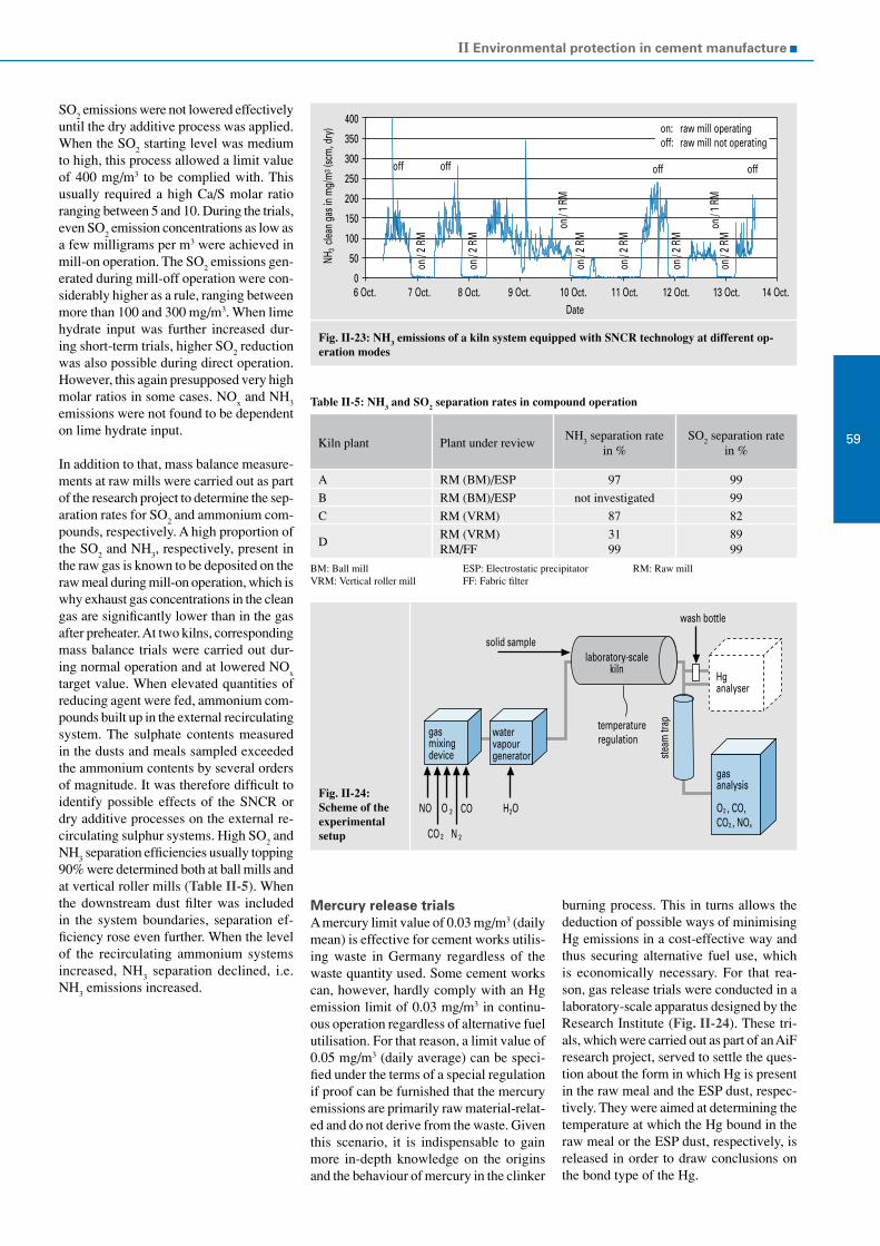
II Environmental protection in cement manufacture
59
SO2 emissions were not lowered effectively
until the dry additive process was applied. When the SO
2 starting level was medium
to high, this process allowed a limit value of 400 mg/m3 to be complied with. This usually required a high Ca/S molar ratio ranging between 5 and 10. During the trials, even SO
2 emission concentrations as low as
a few milligrams per m3 were achieved in mill-on operation. The SO
2 emissions gen-
erated during mill-off operation were con-siderably higher as a rule, ranging between more than 100 and 300 mg/m3. When lime hydrate input was further increased dur-ing short-term trials, higher SO
2 reduction
was also possible during direct operation. However, this again presupposed very high molar ratios in some cases. NO
x and NH
3
emissions were not found to be dependent on lime hydrate input.
In addition to that, mass balance measure-ments at raw mills were carried out as part of the research project to determine the sep-aration rates for SO
2 and ammonium com-
pounds, respectively. A high proportion of the SO
2 and NH
3, respectively, present in
the raw gas is known to be deposited on the raw meal during mill-on operation, which is why exhaust gas concentrations in the clean gas are significantly lower than in the gas after preheater. At two kilns, corresponding mass balance trials were carried out dur-ing normal operation and at lowered NO
x
target value. When elevated quantities of reducing agent were fed, ammonium com-pounds built up in the external recirculating system. The sulphate contents measured in the dusts and meals sampled exceeded the ammonium contents by several orders of magnitude. It was therefore difficult to identify possible effects of the SNCR or dry additive processes on the external re-circulating sulphur systems. High SO
2 and
NH3 separation efficiencies usually topping
90% were determined both at ball mills and at vertical roller mills (Table II-5). When the downstream dust filter was included in the system boundaries, separation ef-ficiency rose even further. When the level of the recirculating ammonium systems increased, NH
3 separation declined, i.e.
NH3 emissions increased.
Fig. II-23: NH3 emissions of a kiln system equipped with SNCR technology at different op-eration modes
Table II-5: NH3 and SO2 separation rates in compound operation
Kiln plant Plant under reviewNH
3 separation rate
in %SO
2 separation rate
in %
A RM (BM)/ESP 97 99
B RM (BM)/ESP not investigated 99
C RM (VRM) 87 82
DRM (VRM)RM/FF
3199
8999
BM: Ball mill ESP: Electrostatic precipitator RM: Raw mill VRM: Vertical roller mill FF: Fabric filter
Mercury release trialsA mercury limit value of 0.03 mg/m3 (daily mean) is effective for cement works utilis-ing waste in Germany regardless of the waste quantity used. Some cement works can, however, hardly comply with an Hg emission limit of 0.03 mg/m3 in continu-ous operation regardless of alternative fuel utilisation. For that reason, a limit value of 0.05 mg/m3 (daily average) can be speci-fied under the terms of a special regulation if proof can be furnished that the mercury emissions are primarily raw material-relat-ed and do not derive from the waste. Given this scenario, it is indispensable to gain more in-depth knowledge on the origins and the behaviour of mercury in the clinker
burning process. This in turns allows the deduction of possible ways of minimising Hg emissions in a cost-effective way and thus securing alternative fuel use, which is economically necessary. For that rea-son, gas release trials were conducted in a laboratory-scale apparatus designed by the Research Institute (Fig. II-24). These tri-als, which were carried out as part of an AiF research project, served to settle the ques-tion about the form in which Hg is present in the raw meal and the ESP dust, respec-tively. They were aimed at determining the temperature at which the Hg bound in the raw meal or the ESP dust, respectively, is released in order to draw conclusions on the bond type of the Hg.
Fig. II-24:Scheme of the experimental setup
400
350
300
250
200
150
100
50
06 Oct.
NH3 c
lean
gas i
n m
g/m
3 (sc
m, d
ry)
7 Oct. 8 Oct. 9 Oct. 10 Oct. 11 Oct. 12 Oct. 13 Oct. 14 Oct.Date
off off off off
on / 2
RM
on / 2
RM
on / 1
RM
on / 2
RM
on / 2
RM
on / 2
RM
on / 2
RM
on / 1
RM
on:off:
raw mill operatingraw mill not operating
gasmixingdevice
watervapourgenerator
laboratory-scalekiln
NO
CO 2
O 2
N 2
H2O
temperatureregulation
Hganalyser
solid sample
gasanalysis
O2 , CO,CO2 , NOx
CO
wash bottle
steam
trap

VDZ Activity Report 2005 – 2007
60
The laboratory-scale kiln, the develop-ment of which was tailored to the reaction conditions prevailing in the preheater of rotary kilns in the cement industry, allows solid samples to be purposefully exposed to gases of arbitrary composition at a tem-perature range from 20 to 1 000 °C.
First a gas atmosphere of certain composi-tion (constituents: N
2, CO
2, O
2 and CO if
necessary) is produced synthetically in a gas mixing device. In this way, the compo-sition of exhaust gas from a rotary kiln can be simulated. The gas mixture thus gener-ated is passed into the laboratory kiln. An accurately weighted quantity (approx. 1 g raw meal or 0.2 g filter dust, respectively) of the solid sample to be investigated was fed to the kiln in advance. Conclusions on the reaction of the solid and the gas phase can be drawn from measuring the gas com-position of the escaping gas.
An analyser for continuous mercury emis-sion measurement is employed to measure the mercury concentration in the exhaust gas flow. To that end, the hot gas sample is passed directly into the Hg measuring instrument via a heated flexible gas tube. To distinguish whether the mercury is present in the samples in compounds or as elemen-tal Hg, the investigations were conducted both with and without a catalyst. When the catalyst integrated in the mercury emission analyser is bypassed, the instrument only detects elemental Hg in the exhaust gas, while operation including catalyst also detects mercury compounds. Temperature and concentration are recorded by a meas-ured data acquisition unit and made avail-able to a measurement data processor for evaluation. Exhaust gas composition (CO,
CO2, NO
x, O
2) is continuously measured by
series-connected gas analysers. Gas release takes place in air on the one hand and un-der raw gas conditions on the other hand. The samples are heated up from ambient temperatures to 1 000 °C at a constant rate in this process. The mercury content of the samples investigated was analysed at the laboratory in advance.
It becomes evident from the initial tri-als that, regardless of the test conditions, most of the Hg contained in the raw meal (approx. 1 ppm) is released at the tem-perature range under review. As expected, the Hg contents in the samples heated up were largely below the detection limit of 0.02 mg/kg after test conclusion. When the catalyst had been bypassed, the Hg concentration readings of the measuring instrument were lower than in the trials dur-ing which the gas had been passed via the catalyst. This is attributable to the fact that, as expected, use of the catalyst allowed Hg compounds (e.g. HgCl
2) to be detected by
the measurement as well.
The curves for gas release from raw meal under raw gas conditions (3 vol.% oxygen) and under atmospheric conditions obtained when the catalyst was included (total mer-cury) and bypassed (elemental mercury only) that are depicted in Fig. II-25 serve as an example for gas release curves.
It becomes obvious from the curves for gas release from raw meal under atmospheric conditions (black and blue lines) that the mercury contained in the raw meal is re-leased at different times and temperatures, respectively. This indicates that it is present in different types of combination or dif-
Fig. II-25: Curves for Hg gas release from raw meal under varying trial conditions
ferent forms of adsorption on the solids surface, respectively. At temperatures above about 200 °C, only a small portion of the mercury contained in the raw meal is released at first. The largest portion of the mercury by far is subsequently released, followed by a further small portion. The further release observed at temperatures above these might be attributable to the retention effect of the test apparatus. A comparison of the two curves (with cata-lyst/black line and without catalyst/blue line) highlights that the first release taking place at approx. 200 °C must be attribut-able to the release of elemental or adsorbed mercury. According to present knowledge, the subsequent significant release can be traced back to the release of Hg(II)O or a mix of easily volatilised mercury com-pounds, for example. When the catalyst is bypassed (blue line), comparably little Hg is detected at that point of time. This sug-gests that the Hg released is not exclusively elemental Hg, but a type of Hg combination (possibly Hg+ or Hg2+ compounds) that is reduced when it passes the catalyst. This mercury proportion of the raw meal was, however, not fully detected during passage through the catalyst. It is possible that only bivalent mercury is quantitatively convert-ed to elemental and thus measurable mer-cury in the catalyst. By contrast, univalent mercury may be converted to elemental, i.e. measurable form on a small scale only. This means that these Hg compounds are not fully converted to elemental mercury by the catalyst.
It further becomes evident from the chart that the reaction conditions, i.e. the gas composition, have an impact on the time of release. Under raw gas conditions, the time of release is shifted towards higher temperatures. The conversion of the Hg compounds present to elemental mercury – which can be detected by the photometer of the analyser for continuous mercury emission measurement – is obviously re-tarded under raw gas conditions. This conforms to the assumptions mentioned above as the occurrence of bivalent Hg compounds is clearly higher than that of univalent compounds under oxidising conditions. Accordingly, higher mercury quantities were detected under oxidising conditions (in air) than under raw gas conditions since the bivalent type of com-bination can be converted to the elemental form more easily.
More in-depth investigations are scheduled to be carried out as part of AiF research project No. 14547 to clarify the phenomena cited above.
12 000
10 000
8 000
6 000
4 000
2 000
0
Progress with time in s
Conc
entra
tion
in p
pt/
C
0 100 200 300 400 500 600 700 800 900 1000
raw meal in air without cat.raw meal in raw gas without cat.raw meal in raw gas with cat.raw meal in air with cat.
Heat-up rate 60 °C/min

II Environmental protection in cement manufacture
61Noise protection
To extrapolate the noise reduction measures taken at a cement works in south Germany, the Environmental Monitoring Body was engaged to elaborate a noise prognosis as a basis for the project planning of a noise protection screen for the planetary cooler of a rotary kiln. Given its position at the bottom of a valley, the rotary kiln radiated without hindrance to the adjacent, more elevated residential buildings. The noise-related advisory services were based on a plant-specific noise map.
Constituting the main source of noise, the planetary cooler largely determined the ambient noise level in the vicinity of the works. In order to reduce the noise propagation from the planetary cooler to a level no longer relevant for ambient noise levels, the works management decided to commission the installation of a noise protection screen.
Noise protection screen for planetary coolerThe high noise emissions from planetary coolers are generated by the impact of the clinker on the metal walls in the cooling tube section that is not brick-lined. Noise development mainly depends on the par-ticle size distribution of the clinker and on the lifting blade models in the cooling tubes. The noise occurs in all tubes simul-taneously as the kiln rotates, which results in a high acoustic capacity level. When sound radiation is not impeded, planetary coolers may therefore be audible even from a fairly large distance.
The noise of material falling down at the cooler outlet and the noise emission caused by the crusher are of subordinate importance for overall emission from the cooler. The plate belt for transporting the hot clinker may contribute to the con-spicuous nature of the noise emission by squeaking sounds. Squeaking sounds may be produced because the plate belt cannot be lubricated owing to the high clinker temperature.
The noise emission in the immediate vicin-ity of the clinker cooler was determined by measuring. Measured at a horizontal dis-tance of 4 to 5 m from the cooling tubes, the acoustic noise level averaged 95 dB(A). The maximum acoustic noise level was in a frequency range between 1 000 Hz and 2 000 Hz.
Noise-insulating encapsulation of the individual cooling tubes was rendered impossible by the high shell temperatures and the required heat removal by radiation and convection. When the planetary cooler needs to be screened from its surroundings to one side only, which was the case with the cooler under review, one noise screen may suffice. The screen has to be posi-tioned close to the cooler, however, and be considerably higher and longer than it.
The noise reduction that can be expected to be caused by a sound screen can be de-termined using noise propagation calcula-tion. The noise emission of the planetary cooler was to be reduced by a minimum of 8 dB(A) by the shielding effect of the noise protection screen. It chiefly depends on
the ratio of the effective screen height, the noise wavelength and the so-called shadow angle. As the wavelength decreases with a rise in frequency, screening efficiency at high frequencies is better than at low frequencies. In the case of the planetary cooler, a dominant frequency of 1 000 Hz was assumed as the most unfavour-able estimate. This corresponds to a noise wavelength of approx. 0.34 m.
The screening effect of the noise protection screen was enhanced by a noise-absorbing lining on the wall surface facing the emis-sion side. Noise reflecting walls located in the immediate vicinity of the cooler basi-cally diminish the screening effect. For that reason, the concrete walls of the clinker silo were taken into account in calculating ambient noise levels.
In the present case, the screening wall towers 7.5 m above the cooler and is 19 m longer on the sides. Large air inlets were provided in the bottom part of the wall to improve air circulation and the associated heat removal. These inlets are equipped with absorptive silencers.
As far as subjective auditory impression is concerned, the noise protection screen has met expectations. Further ambient noise level measurements in the vicinity of the works are to be performed to verify the 8 dB(A) screening effect of the noise protec-tion screen by measurement.
Figs. II-26 and II-27 show the situation before and after erection of the noise pro-tection screen.
Fig. II-26: Situation before erection of the sound screen Fig. II-27: Situation after erection of the sound screen

VDZ Activity Report 2005 – 2007
62 Performance of cement
III
Calcite crystals on the CSH phases of a concrete sample
The economic and ecological importance of cements with several main constituents has increased markedly in the past years and will keep growing. For that reason, the Research Institute continued its intensive work on the impact of the chemical reactivity of blastfurnace slag on the strength development of cements. Contrary to previous assumptions, high compressive strengths can be achieved with blastfurnace slags of fairly low chemical reactivity. This is due to the fact that the gelatinous reaction products that reactive blastfurnace slags form at an early stage of hydration reduce strength. Proceeding from these findings, new approaches for optimising blastfurnace cement properties were derived.
The growing market share of CEM II and CEM III cements resulted in a greater need for reliable and user-friendly methods for determining cement composition. The Research Institute therefore investigated the potential use of X-ray diffractometry methods in quantifying the blastfurnace slag content of cements. The results confirm that X-ray powder diffractometry is an efficient and ad-equately reliable alternative to the analysis methods applied previously.
The performance of cements with several main constituents does not only depend on reactivity, but also on the particle size distribu-tion of the various components. Corresponding investigations, e.g. on cements containing blastfurnace slag or fly ash, were conducted as part of several research projects. They showed that varying the particle size distributions of the main constituents was the only possibility of optimising the strength development of the cements.
The kiln dusts generated during clinker production were primarily recovered via a recirculation systems integrated into the plant so far. Investigations carried out by the Research Institute revealed that bypass dust can be substituted for primary raw materials in the production of glass and mineral foam products. This new channel of utilisation is of economic interest both for the cement industry and the glass industry.
The systematic investigation of cement hydration frequently presupposes clinkers of defined phase composition. The production of such clinkers is difficult, however; it is easier to mix clinker phases produced separately. For that reason, investigations were con-ducted to compare the hydration of industrial and laboratory-made cements. The course of hydration of cements made from separate clinker phases turned out to tally very well with that of industrial cements of identical composition.
In addition to sulphate resistance testing using quick tests, the Research Institute has also carried out tests under practical conditions for several years. In these tests, the sulphate concentration of the attacking medium and the water/cement ratio are limited. Moreover, the tests are carried out at low ambient temperature. In this way, it was verified that the results of these tests reflect the conditions prevailing in building practice more precisely than the quick test methods commonly used in Germany at present.

III Performance of cement
63

VDZ Activity Report 2005 – 2007
64
Table III-1: Chemical composition of Portland cements of different strength classes; given in mass %, including loss on ignition
Chemico-mineralogical composition
The chemical composition of the cements manufactured by the VDZ’s member works is regularly analysed by X-ray fluorescence analysis. Table III-1 summarises the mean, maximum and minimum values of the
CEM I
Strength class
32.5 R 42.5 N 42.5 R 52.5 N 52.5 R
min mean max min mean max min mean max min mean max min mean max
SiO2
18.49 20.09 22.54 18.52 20.75 23.55 18.53 20.05 23.34 19.13 20.19 22.27 18.65 20.20 22.50
Al2O
33.78 5.00 6.12 3.74 4.56 5.63 3.79 4.93 5.85 3.96 4.84 5.47 3.52 4.79 6.11
TiO2
0.20 0.26 0.33 0.19 0.24 0.29 0.21 0.25 0.30 0.21 0.25 0.31 0.20 0.25 0.30
Fe2O
31.32 2.67 4.44 1.31 2.33 4.39 1.29 2.62 4.27 1.36 2.49 3.47 1.16 2.36 4.29
Mn2O
30.04 0.08 0.60 0.04 0.09 0.50 0.04 0.08 0.61 0.04 0.06 0.10 0.03 0.07 0.48
P2O
50.04 0.22 0.55 0.08 0.19 0.54 0.03 0.21 0.56 0.08 0.23 0.56 0.05 0.20 0.43
CaO 60.62 63.00 65.75 63.08 64.14 65.77 60.46 62.97 65.68 61.70 63.57 65.25 60.98 63.86 66.92
MgO 0.73 1.63 3.66 0.61 1.05 1.69 0.61 1.61 3.44 0.78 1.43 2.78 0.65 1.40 3.16
SO3
2.23 2.94 3.29 2.57 2.80 3.26 2.64 3.23 3.93 2.76 3.20 3.69 2.33 3.33 3.84
K2O 0.41 0.93 1.57 0.41 0.75 1.00 0.39 0.93 1.59 0.45 0.83 1.61 0.37 0.84 1.54
Na2O 0.09 0.22 0.54 0.11 0.19 0.29 0.10 0.22 0.47 0.09 0.20 0.27 0.09 0.21 0.44
Na2O
eq0.46 0.84 1.36 0.49 0.69 0.85 0.46 0.84 1.35 0.50 0.82 1.49 0.42 0.77 1.21
l.o.i. 1.49 2.98 4.35 1.52 2.93 4.35 0.92 2.84 4.56 1.14 2.65 4.11 0.88 2.50 4.55
Portland cements of the different strength classes according to EN 197. The repre-sentation of CEM I 32.5 of ordinary early strength (N cements) can be dispensed with for the first time as this cement type is only produced with the special “LH/SR” property (low heat of hydration, high sulphate resistance) at a small number of sites any more.
Market shares continued to shift in favour of Portland-composite cements. In addition to common cement types, increasing quan-tities of so-called M cements (with several main constituents) are produced. CEM II/B-M (S-LL) cements, which comprise both blastfurnace slag and limestone as the main cement constituents, clearly account for the largest share. The chemical composition of
Table III-2: Chemical composition of CEM II cements; given in mass %, including loss on ignition
CEM II
Cementtype
CEM II/A-S CEM II/B-S CEM II/A-LL CEM II/B-P CEM II/B-M (S-LL)
min mean max min mean max min mean max min mean max min mean max
SiO2
20.27 21.88 25.18 20.51 23.97 25.63 16.87 18.12 21.80 27.68 29.84 32.22 18.16 20.31 23.10
Al2O
34.65 5.89 6.62 5.23 6.78 7.73 3.43 4.52 5.54 6.71 8.38 9.84 4.94 5.75 6.72
TiO2
0.23 0.31 0.41 0.29 0.37 0.54 0.19 0.23 0.30 0.35 0.41 0.46 0.24 0.29 0.39
Fe2O
31.05 2.47 3.13 1.13 2.05 3.04 1.12 2.53 4.13 3.31 3.77 4.34 1.46 2.21 3.87
Mn2O
30.05 0.13 0.25 0.07 0.16 0.44 0.03 0.08 0.59 0.07 0.13 0.21 0.05 0.18 0.67
P2O
50.07 0.17 0.52 0.06 0.15 0.43 0.07 0.18 0.41 0.07 0.19 0.44 0.05 0.16 0.37
CaO 57.81 59.82 62.05 53.28 56.63 60.32 58.55 62.20 64.80 40.25 46.05 52.06 51.19 58.39 60.42
MgO 1.63 2.76 4.43 1.77 3.70 5.60 0.66 1.44 3.76 1.12 1.73 2.29 1.48 2.50 5.43
SO3
2.30 3.07 3.98 2.07 2.86 3.66 2.19 2.91 3.66 1.80 2.57 3.39 1.36 2.46 2.98
K2O 0.50 0.95 1.36 0.47 0.82 1.38 0.29 0.87 1.55 1.14 1.81 2.43 0.73 0.96 1.40
Na2O 0.14 0.23 0.35 0.14 0.26 0.68 0.08 0.17 0.29 0.52 0.91 1.41 0.15 0.22 0.35
Na2O
eq0.58 0.86 1.23 0.58 0.80 1.35 0.31 0.74 1.22 1.27 2.10 3.01 0.68 0.86 1.16
S2- 0.07 0.20 0.31 0.16 0.33 0.44 - 0.06 0.13 - - - 0.14 0.27 0.41
l.o.i. 1.11 2.21 3.45 0.77 2.07 3.25 3.65 6.73 8.84 3.29 4.23 5.55 4.90 6.42 8.92
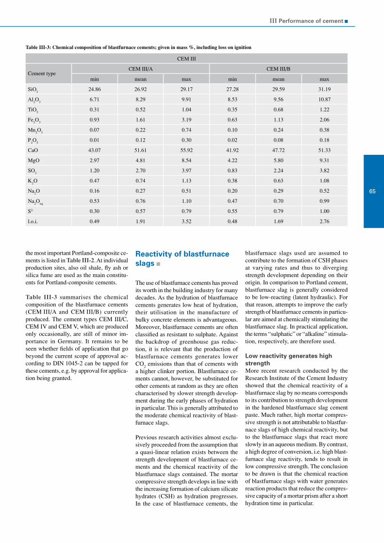
III Performance of cement
65
CEM III
Cement typeCEM III/A CEM III/B
min mean max min mean max
SiO2
24.86 26.92 29.17 27.28 29.59 31.19
Al2O
36.71 8.29 9.91 8.53 9.56 10.87
TiO2
0.31 0.52 1.04 0.35 0.68 1.22
Fe2O
30.93 1.61 3.19 0.63 1.13 2.06
Mn2O
30.07 0.22 0.74 0.10 0.24 0.38
P2O
50.01 0.12 0.30 0.02 0.08 0.18
CaO 43.07 51.61 55.92 41.92 47.72 51.33
MgO 2.97 4.81 8.54 4.22 5.80 9.31
SO3
1.20 2.70 3.97 0.83 2.24 3.82
K2O 0.47 0.74 1.13 0.38 0.63 1.08
Na2O 0.16 0.27 0.51 0.20 0.29 0.52
Na2O
eq0.53 0.76 1.10 0.47 0.70 0.99
S2- 0.30 0.57 0.79 0.55 0.79 1.00
l.o.i. 0.49 1.91 3.52 0.48 1.69 2.76
Table III-3: Chemical composition of blastfurnace cements; given in mass %, including loss on ignition
the most important Portland-composite ce-ments is listed in Table III-2. At individual production sites, also oil shale, fly ash or silica fume are used as the main constitu-ents for Portland-composite cements.
Table III-3 summarises the chemical composition of the blastfurnace cements (CEM III/A and CEM III/B) currently produced. The cement types CEM III/C, CEM IV and CEM V, which are produced only occasionally, are still of minor im-portance in Germany. It remains to be seen whether fields of application that go beyond the current scope of approval ac-cording to DIN 1045-2 can be tapped for these cements, e.g. by approval for applica-tion being granted.
Reactivity of blastfurnace slags
The use of blastfurnace cements has proved its worth in the building industry for many decades. As the hydration of blastfurnace cements generates low heat of hydration, their utilisation in the manufacture of bulky concrete elements is advantageous. Moreover, blastfurnace cements are often classified as resistant to sulphate. Against the backdrop of greenhouse gas reduc-tion, it is relevant that the production of blastfurnace cements generates lower CO
2 emissions than that of cements with
a higher clinker portion. Blastfurnace ce-ments cannot, however, be substituted for other cements at random as they are often characterised by slower strength develop-ment during the early phases of hydration in particular. This is generally attributed to the moderate chemical reactivity of blast-furnace slags.
Previous research activities almost exclu-sively proceeded from the assumption that a quasi-linear relation exists between the strength development of blastfurnace ce-ments and the chemical reactivity of the blastfurnace slags contained. The mortar compressive strength develops in line with the increasing formation of calcium silicate hydrates (CSH) as hydration progresses. In the case of blastfurnace cements, the
blastfurnace slags used are assumed to contribute to the formation of CSH phases at varying rates and thus to diverging strength development depending on their origin. In comparison to Portland cement, blastfurnace slag is generally considered to be low-reacting (latent hydraulic). For that reason, attempts to improve the early strength of blastfurnace cements in particu-lar are aimed at chemically stimulating the blastfurnace slag. In practical application, the terms “sulphatic” or “alkaline” stimula-tion, respectively, are therefore used.
Low reactivity generates high strengthMore recent research conducted by the Research Institute of the Cement Industry showed that the chemical reactivity of a blastfurnace slag by no means corresponds to its contribution to strength development in the hardened blastfurnace slag cement paste. Much rather, high mortar compres-sive strength is not attributable to blastfur-nace slags of high chemical reactivity, but to the blastfurnace slags that react more slowly in an aqueous medium. By contrast, a high degree of conversion, i.e. high blast-furnace slag reactivity, tends to result in low compressive strength. The conclusion to be drawn is that the chemical reaction of blastfurnace slags with water generates reaction products that reduce the compres-sive capacity of a mortar prism after a short hydration time in particular.

VDZ Activity Report 2005 – 2007
66
Blastfurnace slags that engender low com-pressive strength in blastfurnace cement react comparatively quickly in an aqueous medium, forming distinctly differentiated layers of hydration products. As far as their contribution to the compressive strength of blastfurnace cement is concerned, however, high-performance blastfurnace slags react markedly slower. The aluminium portion that is still available after dominant prior reactions, especially with magnesium, is essential in this context. The higher the alu-minium portion, the lower is blastfurnace slag corrosion, i.e. the chemical conversion of the glass matrix that progresses into the blastfurnace slag grain from outside. Investigations conducted by the Research Institute of the Cement Industry further show that the kinetics of blastfurnace slag hydration and the sulphate supply of the cement undergoing hydration are closely connected. This is indicated by the more marked ettringite formation displayed by blastfurnace cements containing high-alu-minium, low-reacting blastfurnace slags.
Aluminium acts as a corrosion inhibitor in the corrosion of industrial glasses. This is attributed, among other factors, to the for-mation of aluminosilicates, which exhibit highly impenetrable, multi-dimensionally cross-linked structures and thus constitute a barrier to diffusion.
Five mechanisms involved in the corrosion of industrial glasses have been discussed in publications. The corresponding model assumptions can in principle also be trans-ferred to blastfurnace slag glass.
Availability of aluminium is decisiveThe investigation of five blastfurnace slags (A to E) of vastly different chemical composition revealed that the corrosion of high-aluminium blastfurnace slag glass is reduced. This is also the case with high-alu-minium industrial glasses. As an example, Figs. III-1 and III-2 show blastfurnace slags A and D after 7-day suspension in water (mass ratio blastfurnace slag/water = 1/2). The high-aluminium blastfurnace
slags A and B suffered only minor corro-sion after the suspension procedure. With the low-aluminium blastfurnace slags C, D and E, corrosion is much more pronounced. At the same time, the individual blastfur-nace slag particles agglomerate by gluing together the gelatinous corrosion layers formed. Collision with other particles and the vessel wall deforms the capsules made up of reaction products, which are obviously plastic (Fig. III-3), and may be present in vastly varying degrees of dif-ferentiation in the individual blastfurnace slags (Fig. III-3 and Fig. III-4).
As investigations progressed, it became evident that the decisive aluminium con-tent is not the overall aluminium content of the blastfurnace slags, but the propor-tion not combined in stable reaction prod-ucts that are formed at a very early stage. Such a reaction product is, for example, the hydrotalcite-type phase, which is formed by the combination of aluminium and magnesium in a mixed hydroxide (Mg
4Al
2(OH)
14·3H
2O).
Fig. III-1: Scanning electron microscope photograph of blastfurnace slag A after seven-day suspension in water
Fig. III-2: Scanning electron microscope photograph of blastfurnace slag D after seven-day suspension in water
Fig. III-3: Scanning electron microscope photograph of blastfurnace slag D after seven-day suspension in water (polished section)
Fig. III-4: Differentiated corrosion rims around an unhydrated blastfurnace slag particle core and their main chemical constituents (polished section)
unhydrated blastfurnace slag core
CaO: 21%SiO2: 57%Al2O3: 12%MgO: 7%
CaO: 17%SiO2: 36%Al2O3: 21%MgO: 20%

III Performance of cement
67
Fig. III-5 shows the aluminium proportion in blastfurnace slags A to E that cannot be combined in a hydrotalcite-type phase according to stoichiometric calculations (AL
nh). The available aluminium portion
ALnh
and mortar compressive strength (Fig. III-6) decrease along the sequence of the five blastfurnace slags A to E. By contrast, the silicon dioxide content shows tenden-cies to increase (Fig. III-7). Research results suggest that the aluminium content AL
nh slows down the progress of corro-
sion. This is presumably attributable to the formation of high-density aluminosilicates which enhance the corrosion resistance of the blastfurnace slag particles.
What role does silicon play?In comparison to blastfurnace slags A and B, blastfurnace slags C, D and E have high silicon and low aluminium contents. As a consequence, silicon can be combined in aluminosilicates to a smaller extent only in blastfurnace slags C, D and E. The fairly high silicon proportion remaining in these blastfurnace slags may lead to silicon ox-
ide being present in the form of silicate hydrogel at least temporarily. Following their suspension in water, blastfurnace slags D and E in particular display corre-spondingly marked high-silicon gel rims (Fig. III-3). If the marked gel rims are the cause of reduced mortar compressive strength, strength is bound to be diminished as the potential for the prevention of these gel rims declines. This potential becomes lower in line with an increase in excess silicate in the blastfurnace slags that cannot be combined with aluminium in the form of aluminosilicates. In a first approximation, this excess silicate can be calculated as the difference between the Si content and the aluminium portion AL
nh of the blastfurnace
slags available for this reaction (Fig. III-8). This consideration provides a possible chemico-mechanical explanation for the empirical finding that blastfurnace slags to be used as cement constituents must not be acidic, i.e. should not contain excessive quantities of SiO
2.
The relationships described indicate that the formation of high-silicate plastic gel layers is the reason why the early mortar strength of blastfurnace cements is often low. This is particularly true after short hydration periods.
The further progress of the process during which these gel layers harden to become microstructural elements of compressive capacity may vary vastly, taking place more quickly in some blastfurnace cements than in others. This becomes evident from the following example based on three blast-furnace cements. Blastfurnace cements 1, 2 and 3 merely differ in terms of the blastfurnace slags 1, 2 and 3, respectively, of which they contain 65 mass %. The type and proportion by mass of the clinker and the sulphate agent are identical in all three blastfurnace cements.
The compressive strengths of blastfurnace cement 1 and blastfurnace cements 2 and 3 shown in Fig. III-9, which differ signifi-cantly at first, lessen in the course of 28
Fig. III-5: Available aluminium proportion of blastfurnaceslags A to E
Fig. III-6: Mortar compressive strength of blastfurnace slags A to E
Fig. III-7: Silicon dioxide content of blastfurnace slags A to EFig. III-8: Correlation between the excess silicon in blastfurnace slags A to E and the mortar compressive strengths of blastfurnace cements A to E
14
12
10
8
6
4
2
0
Alnh
in m
ol%
BS A BS B BS C BS D BS E
50454035302520151050Ce
men
t com
pres
sive s
treng
th in
MPa
Cement A Cement B Cement C Cement D Cement E
7 days28 days56 days
393837363534333231302928
SiO 2
cont
ent o
f the
blas
tfurn
ace s
lags
in
mas
s %
BS A BS B BS C BS D BS E
50454035302520151050
Mor
tar c
ompr
essiv
e stre
ngth
s of
blas
tfurn
ace c
emen
ts A
to E
in M
Pa
Difference between the Si content in mol% and theAlnh content of blastfurnace slags A to E in mol%
15 20 25 30 35
7 days28 days56 days

VDZ Activity Report 2005 – 2007
68
days. The compressive strengths are put in relation to those of blastfurnace cement 1 (= 100%), which possessed the highest compressive strength of the three cements after two days of hydration. Blastfurnace cement 2 achieved only about 50% of the strength of blastfurnace cement 1 at first, but exceeded it after 28 days. Blastfurnace cement 3 displayed behaviour that is typi-cal of fairly low-performance blastfurnace slag. After a hydration time of two days, mortar compressive strength of the respec-tive blastfurnace cement 3 also achieved only about 50% of the value measured for blastfurnace cement 1. This relative differ-ence is not even compensated entirely as hydration time progresses. After 28 days, blastfurnace cement 3 possesses merely 80% of the compressive strength of blast-furnace cement 1.
Following a comparable “weak” begin-ning, blastfurnace cements 2 and 3 thus displayed differences in the efficiency of strength gain as hydration progressed further. This indicates that the situation
regarding mechanical compressive capac-ity prevailing in the mortar prism micro-structure is similar initially, but changes at different rates then. The capacity of the blastfurnace slags to convert the gelatinous reaction products formed at an early stage into microstructure elements of compres-sive capacity may thus differ although the initial corrosion resistance of the blast-furnace slag glass is comparable. In the case of blastfurnace slags 2 and 3, it was not the rapid corrosion of the blastfurnace slag glass that was prevented; rather, the transformation of the gel layers formed proceeded differently. The Research Insti-tute is currently pursuing new investigation approaches that also incorporate fracture mechanics to explain this effect.
New ways of optimising blastfurnace cements are conceivableBased on these new findings on the reac-tivity of blastfurnace slags made by the Research Institute of the Cement Industry, utterly new approaches to optimising the
Fig. III-9:Relativedevelopment of the mortar compressive strengths of three blastfur-nace cements (BFC)
properties of blastfurnace cements open up. If the assumed relationships between the formation of plastic gel layers around the corroding blastfurnace slag particles and the compressive strength of blastfur-nace cements are correct, it is necessary not to stimulate, but rather to purposefully diminish the corrosion of low-performance blastfurnace slags in order to increase the early strength of blastfurnace cements.
The examination of these new model assumptions currently constitutes a key research topic at the Research Institute of the Cement Industry.
Glass products derived from kiln dusts of thecement industry
The burning of Portland cement clinker in rotary kilns produces dust that is separated during exhaust gas purification or in bypass systems. Most of this kiln dust is utilised as a minor additional cement constitu-ent. This requires taking into account the customers’ demands, standard criteria and more extensive regulations relating to the alkali content of cement, for example. Use as a raw material constituent in glass pro-duction represents a new way of utilising the material properties of these kiln dusts. Basically, this opens up the prospect of part of the customary glass raw materials being replaced by kiln dust.
When a glass batch of silicate nature is melted, alkali compounds are usually added as fluxing agents. Alkali-contain-ing dusts generated in cement manufac-ture can perform this function. The other constituents of these dusts are calcareous and siliceous compounds also needed in the mix formulation of a glass batch. In mineralogical terms, the kiln dusts may be made up of raw meal components that are not converted or calcined to some extent, and clinker dust enriched in free lime, al-kali sulphates and alkali halides, as well as further intermediate products of the clinker formation process. Their composition al-lows them to be substituted for part of the primary raw materials of glass. The degree of substitution chiefly depends on their chemical composition with regard to the adjustability of defined batch compositions and with regard to volatile and gas-form-ing constituents, respectively. Moreover, hydraulically active dust constituents that act as a binder when the batch raw ma- terials are converted to granules prior to the actual melting process can be of additional advantage. Finally, release agents that can
Fig. III-10: Evaluation of the dust survey – ratio of the alkali content and the contents of sulphate and chloride
120
100
80
60
40
20
0
Cem
ent c
ompr
essiv
e stre
ngth
in %
of t
he co
mpr
essiv
e stre
ngth
in 1
2 7 28Duration of hydration in days
BFC 1 BFC 2BFC 3
SO3 + Cl CaO, SiO2, Al2O3and otherconstituents
Na2O + K2O
60
80
70
90
100
50
40
30
20
10
0 100
90
80
70
60
50
40
20
30
10
00 10 20 30 40 50 60 8070 90 100

III Performance of cement
69
also be replaced by bypass or electrostatic precipitator dust are used in the manufac-ture of foamed or frothed glass products.
As sufficient quantities of bypass dust are generated, it appears reasonable to use them especially for the production of bulk glass in the glass industry. Investigation results available to date suggest the uti-lisation of the alkaline by-products in the product ranges of glass fibres (batch con-stituent, strength formation agent), insu-lant fibres (secondary binder) and mineral foam (batch constituent) in particular. Co- operating with the Weimar Material Re-search and Testing Institute in an AiF-spon-sored research project, the Research Insti-tute of the Cement Industry furnished proof that this kind of utilisation is possible.
In order to assess the principal suitability for manufacturing different glass products, a survey was conducted initially to ascer-tain the chemical composition of dusts available at the works. On the basis of these results, three sites were selected at which own samples were taken and investigated for homogeneity. Moreover, fairly large quantities of representative dust samples for subsequent glass technology trials were obtained at these sites.
Material preconditionsThe survey results indicated that all the dusts investigated can potentially be used in glass production in principle. The degree
of substitution to which kiln dust from ce-ment manufacture can be substituted for primary raw materials for glass ensues from the respective chemical composi-tion in each individual case. Fig. III-10 is a schematic representation of the survey results. It shows the contents of alkali, sulphate and chloride as well as other con-stituents in a ternary diagram. The position of the data dots highlights that an elevated content of alkalis, which can be regarded as the substantial constituents that are of use in the glass technology domain, inevitably entails an elevated content of SO
3 or Cl,
respectively. It was found that high alkali contents are desirable on the one hand. On the other hand, however, chlorides and sulphates, which act as combination part-ners of the alkalis in the dust, restrict the degree of substitution as they may lead to seed formation in the glass, increased cor-rosion of production facilities, and higher emissions. Elevated CaO contents may be a limiting factor as well if they reduce the viscosity of the melting.
Furthermore, the homogeneity of the com-position is of fundamental importance. Sampling trials carried out at several sites revealed that excessive variation widths in chemical composition can be adequately diminished, e.g. by simple intermediate storage in silos. The variation of measure-ment results is much lower than that of samples taken directly from the bypass, which is also confirmed by the schematic
representation in Fig. III-11. The necessary degree of homogenisation can, however, be expected to be obtained during trans-port or during the filling and emptying of a bulk trailer, respectively, even without prior intermediate storage. Accordingly, the preconditions for indicating the composi-tion per batch in the form of a consignment note are met.
Production of compact glassesGlass batch formulations in which bypass dust from the three selected cement works was used and which corresponded to the composition of customary, chemically re-sistant glass (C glass) were adjusted to pre-pare the semi-commercial scale melting tri-als. Thorough mixing and homogenisation of the input materials was achieved without major technical effort. In conformity with industrial practice, the batches were granu-lated to form spherical aggregates prior to the melting process in order to prevent them from being covered with dust during input into the furnace. In order to keep moisture input and thus energy consump-tion during the melting process as low as possible, air drying was first applied after granule production. The intended stability of the granules was ensured all the same as the kiln dust components had hardened hydraulically in advance.
Subsequently, it was possible to manu-facture seed-free glass products and inter-mediate products in the form of pellets
Fig. III-11: Variation bandwidth of the chemical constituents of bypass dust from a selected cement works
70
60
50
40
30
20
10
0CO2 SiO2 Al2O3 Fe2O3 CaO MgO SO3 K2O Na2O Cl
Composition before intermediate storage silo
Cont
ent i
n m
ass %
Cont
ent i
n m
ass %
70
60
50
40
30
20
10
0CO2 SiO2 Al2O3 Fe2O3 CaO MgO SO3 K2O Na2O Cl
Composition after intermediate storage silo

VDZ Activity Report 2005 – 2007
70
by substituting bypass dust for primary raw materials at rates of up to about 10% (Fig. III-12). The execution of the com-pact founds took place in an electrically heated furnace having a capacity of ap-prox. 80 litres. The maximum temperatures set totalled 1 410 °C. The reference glass batch used was a refuse glass/raw material mix with a refuse glass portion of about 35 mass %, which corresponds to industrial production.
Table III-4 summarises the results of the material and thermal inventory analysis of the melting cycles. The losses in weight of up to 17 mass % of the bypass dust/batch founds recorded were primarily attribut-able to the moisture contents of up to 15 mass % input and to a small extent only to evaporation losses. By contrast, the melt-ing losses obtained in the reference glass batch exclusively resulted from losses due to dusting and evaporation. As far as energy consumption figures are concerned, rela-
Fig. III-12: Production and processing of test pellets containing bypass dust
Batch inputin kg
Conversion rate in kg(%)
Bypass dustproportion in
the batchin mass %
Energyconsumption
in kWh(kWh/kg glass)
Works A ≈ 126≈ 105 (83)
9.6670
(6.37)
Works B ≈ 128≈ 106 (83)
10.4775
(7.31)
Works C ≈ 150≈ 126 (84)
8.4740
(5.87)
Referenceglass batch
≈ 125≈ 111 (89)
-785
(7.09)
Table III-4: Process technology parameters of the melting trials
tive energy consumption values ranging between 83 and 103% are obtained for the batches containing bypass dust if the spe-cific energy expenditure of the reference batch is set at 100%.
Frothed glass and mineral foamsFrothed and foamed glass products, re-spectively, are chiefly used as insulants in the construction industry. During produc-tion, the raw material composition must be chosen so as to match a frothable glass composition as closely as possible. Input of glass into batch/ raw material mixes in the form of glass meal is a simple method of batch correction that has proved techni-cally appropriate. Batch varieties in which a certain proportion of the glass meal was replaced by bypass dust were successfully produced as part of the research project. The subsequent sintering and simulta- neous foaming of the granulates took place at temperatures ranging between about 1 100 and 1 150 °C in a semi-commercial
scale rotary kiln. The hydraulic property of the bypass dust was conducive to the formation of the necessary grain strength of the raw granules.
As expected, low CaO contents in the kiln dusts were conducive to the preconditions for thermal softening and foam formation. Based on the results obtained in tests with substitution rates of 50 to 75 mass %, it is possible to produce light granulates of swelling clay quality.
The foaming of bypass dusts with a high CaO content is more difficult under techno-logical aspects. For that reason, alternative utilisation as a release agent in the produc-tion of frothed glass granulates was discov-ered. As a consequence of the inevitable enrichment of the release agent with con-stituents of the raw material batch during granulates production, part of the release agent continually needs to be replaced. The use of bypass dust with a high CaO portion allowed utilisation of the contaminated release agent as a raw material constituent that can be input into the process again. This possibility of recuperation implied additional technological benefit.
Based on a comparable raw material situa-tion, but on technology that is fundamental-ly different from that of frothed glass gran-ulates production, the suitability of glass meal/bypass dust batches in the production of mineral foam products was verified (Fig. III-13). During trial production at the industrial plant of a mineral foam manu-facturer, substitution rates of 20 mass % were realised without even fully exploit-ing the potential for adjusting temperature conditions. The batch and the process can be further optimised.

III Performance of cement
71
Fibre productsThe pellets containing bypass dust that were generated in the compact found trials were melted on a glass fibre manufacturer’s fibre spinning machine and processed to fibres with filament diameters between 8 and 12 µm for trial purposes. Following fi-brillation, they were spun to 400 tex sliver. The criterion applied for comparison was the performance of ordinary C glass pel-lets in the same sliver machine. Both the processing temperature of about 1 190° C of the pellets containing dust and the number of fibre rips that occurred during atomisation were similar to the reference values obtained from the test with custom-ary pellets. All the charges investigated were textile. All the fibres lent themselves to the production of spools and the subse-quent processing into glass fibre textiles (Fig. III-14).
Economic considerationsThe results of the research project un-derscore the potential that kiln dust from cement manufacture has as a constituent in glass production. This novel way of uti-lisation is interesting both for the cement industry and the glass industry under eco-nomic aspects. For cement manufacturers, it presents alternatives to plant-integrated bypass dust circulation. For the glass in-dustry, it has the prospect of lowering production costs by allowing a percentage of primary raw material constituents to be replaced by dusts from the bypass and ex-haust gas purification plants of the clinker burning process.
It was demonstrated that potential for use is inherent in all the dusts investigated. The glasses obtained by melting were success-fully processed to fibres, while the foamed products could be directly used as insulants of commercial quality. The degree to which kiln dust from cement manufacture can be substituted for glass raw materials depends on the respective chemical composition of the dust in each individual case.
In addition to the useful properties cited above, alkaline dust basically also seems to be suitable for recycling artificial or natural fibre waste. To reincorporate the fibrous or particulate waste into the production process, it can be mixed with alkaline dust, moistened and processed to formed bodies. Its hydraulic hardening properties are taken advantage of in this process. In addition to
Fig. III-13: Mineral foam production
Fig. III-14: Pro-duction of glass fibre spools
acting as binders, the alkaline kiln dusts can further assume the function of an aluminium agent to a certain extent and replace a limit-ed proportion of the primary raw material bauxite (up to 17% in insulant fibres) if they have a high Al
2O
3 content. Additional cost
savings can thus be realised.
The findings obtained on the possible uses in glass product manufacture of alkaline by-products with hydraulic properties con-stitute a first step towards possible indus-trial implementation. This may be accom-plished on the basis of carefully directed continuative investigations conducted in direct cooperation between individual ce-ments works and glass or insulant industry factories, respectively.
Influence of the particle size distribution of main cement constituents
Since the European cement standard EN 197-1 took effect, the significance of ce-ments with several main constituents has been growing continually. As their clinker content is reduced, these cements offer the possibility of keeping specific energy consumption and thus also CO
2 emissions
during manufacture at a low level. Given the large bandwidth of cements avail-able, concrete properties can further be tailored to certain applications even more precisely. The optimisation of the particle size distributions of the main constituents represents a key focus in the development of these cements.
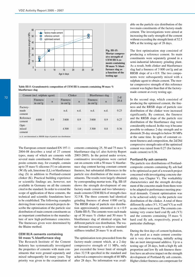
VDZ Activity Report 2005 – 2007
72
The European cement standard EN 197-1: 2004-08 describes a total of 27 cement types, many of which are cements with several main constituents. Portland-com-posite cements may, for example, contain up to 35 mass % siliceous (V) or calcareous (W) fly ash, limestone (LL) or blastfurnace slag (S) in addition to Portland-cement clinker (K). Practical building experience or scientific findings are, however, not available in Germany on all the cements cited in the standard. In order to extend the scope of application of these cements, the technical and scientific foundations have to be established. The following examples deriving from various research projects de-scribe the optimisation of the particle size distribution of main cement constituents as an important contribution to the manufac-ture of new high-performance concretes. The finenesses given were determined by the Blaine method.
CEM III/A cements containing 50 mass % blastfurnace slagThe Research Institute of the Cement Industry has systematically investigated the properties of cements with main con-stituents that were ground separately and mixed subsequently for many years. Top priority was given to the examination of
Cement (incl. sulphate agent) Clinker Blastfurnace slag2 d/ 28 dFineness
in cm2/gn
Fineness in cm2/g
nFineness in cm2/g
n
Factory-made cement
4 000 0.9
n.d. n.d. n.d. n.d. 0.23
Reference cement
3 800 0.9 3 800 0.9 0.27
Opti-mised cement
4 300 1.0 3 300 0.8 0.36
n. d.: not determined; n: RRSB slope of particle size distribution
Fig. III-15:Mortar compres- sive strength of CEM III/A ce-ments containing 50 mass % blast-furnace slag as a function of the testing age
Table III-5: Granulometric composition of CEM III/A cements containing 50 mass %blastfurnace slag
cements containing 25, 50 and 75 mass % blastfurnace slag (cf. also Activity Report 2003-2005). In the period under review, continuative investigations were carried out on cements with a 50 mass % blastfur-nace slag content having constant cement fineness, but substantial differences in the particle size distribution of the main con-stituents. The results were largely obtained by corresponding mortar tests. Fig. III-15 shows the strength development of one factory-made cement and two laboratory-made cements CEM III/A of strength class 32.5 R. The three cements had identical grinding fineness of about 4 000 cm2/g. The RRSB slope of particle size distribu-tion approximately amounted to n = 0.9 (Table III-5). The cements were each made up of 50 mass % clinker and 50 mass % blastfurnace slag of identical origin, but different particle size distribution. The wa-ter demand necessary to achieve standard stiffness totalled 28 mass % in all tests.
The optimisation tests proceeded from the factory-made cement which, at a 2-day compressive strength of 11 MPa, only just exceeded the lower limit of strength class 32.5 R specified in the standard and achieved a compressive strength of 48 MPa after 28 days. No information was avail-
able on the particle size distribution of the two main constituents of the factory-made cement. The investigations were aimed at increasing the early strength of the cement without exceeding the strength limit of 52.5 MPa at the testing age of 28 days.
The first optimisation step consisted of producing a reference cement. Its main constituents were separately ground in a semi-industrial laboratory grinding plant. As a result, both clinker and blastfurnace slag had a fineness of 3 800 cm2/g and an RRSB slope of n = 0.9. The two compo-nents were subsequently mixed with a sulphate agent to obtain cement. The mor-tar compressive strength of this reference cement was higher than that of the factory-made cement at every testing age.
In the second step, which consisted of producing the optimised cement, the fine-ness and the RRSB slope of particle size distribution of the clinker were increased significantly. By contrast, the fineness and the RRSB slope of the particle size distribution of the blastfurnace slag were considerably reduced. In this way it became possible to enhance 2-day strength and to diminish 28-day strength to below 50 MPa at the same time. In spite of constant ce-ment fineness and composition, the 2d/28d compressive strength ratio of the optimised cement was raised from 0.27 (for factory-made cement) to 0.36.
Portland-fly ash cementsThe particle size distributions of Portland-composite cements containing fly ash had to be optimised as part of a research project concerned with investigating concrete dur-ability (see Chapter V). The workability characteristics and the strength develop-ment of the concretes made from them were to be adapted to performance meeting prac-tical demands. Cement optimisation was to be achieved solely via the particle size distribution of the clinker. A total of three different fly ashes (V1, V2 and V3) as well as one clinker were used. The cements con-taining very coarse hard coal fly ash (V3) and the cements containing 35 mass % hard coal fly ash, respectively, posed a particular challenge.
During the first days of cement hydration, fly ash used as a main cement constitu-ent is very slow-reacting, initially acting like an inert interground additive. Up to a testing age of 28 days, both a high fly ash proportion and low fly ash fineness there-fore have an adverse impact on the strength development of Portland-fly ash cements. Higher clinker fineness can compensate for
60
50
40
30
20
10
0
Mor
tar c
ompr
essiv
e stre
ngth
in M
Pa
0 5 10 15 20 25 30
Age in days
factory-made cementreference cementoptimised cement

III Performance of cement
73
this influence to a limited extent only. Bet-ter effects were achieved by significantly increasing the RRSB slope of particle size distribution of the clinker.
Fig. III-16 a) depicts the compressive strength of Portland-fly ash cements con-taining 30 mass % fly ash as a function of their testing age. Fly ash V1 had a fineness of 4 700 cm2/g, while the fineness of fly ash V3 was merely 3 350 cm2/g. First of all, two cements (30% V1 and 30% V3) were made from the fly ashes, a clinker meal with wide particle size distribution (n = 0.75) and a grinding fineness of 4 500 cm2/g, and a sulphate agent. At the ages of 7 and 28 days in particular, the cements exhibited a low strength level. Given the difference in the fineness of the two fly ashes, moreover, a strength difference of about 3 MPa was determined. The strength of the optimised cement containing fly ash V3 (30% V3 optimised) developed differ-ently. Its clinker fineness was only about 4 100 cm2/g, but its particle size distribution was set at a considerably narrower value, i.e. at an RRSB slope of n = 1. This had considerable impact on the particle size dis-tribution of the optimised cement, its water demand and its strength development. The water demand necessary to achieve stand-ard stiffness increased from 27 mass % to 33 mass %. The compressive strengths attained amounted to 26 MPa after 2 days and 48 MPa after 28 days. The concretes made from the optimised cements did not display any significant differences to the reference concretes in terms of workability or strength development.
Cement
Fly ash V2 Clinker
Proportionin mass %
Finenessin cm2/g
n
-
20% V2 20 4 000 approx. 0.8
25% V2 25 4 000 approx. 0.8
30% V2 30 4 500 approx. 0.8
35% V2 35 4 500 approx. 0.8
35% V2 optimised 35 4 080 approx. 1.0
n: RRSB slope of particle size distribution
Fig. III-16: Mortar compressive strength of Portland-fly ash cements as a function of testing age; a) containing 30 mass % hard coal fly ash of different fineness; b) containing 20 to 35 mass % hard coal fly ash
Further investigations served to determine the effects of the fly ash content on ce-ment properties. The fineness of fly ash V2 used in these tests totalled 3 700 cm2/g. Table III-6 gives an overview of the test parameters. The cements containing fly ash V2 that were utilised as part of this test series were to be optimised solely via the particle size distribution of the clinker as well. The compressive strength of the ce-ments at various testing dates is depicted in Fig. III-16 b). The increase in the content of fly ash from 20 to 35 mass % resulted in a significantly lower strength level at every testing age. The adverse effects of the higher fly ash content could only be compensated for by using clinker meal with a narrower particle size distribution (see cement 35% V2 optimised). In spite of its fly ash content of 35 mass %, this ce-ment attained a strength level comparable to that of the cement containing 20 mass % fly ash. The simple method of optimisation described, which initially involved only one main constituent (clinker), resulted in a higher water demand necessary for attain-ing standard stiffness, however. Given the
Table III-6: Granulometric composition of Portland-fly ash cements containing 20 to 35 mass % hard coal fly ash
higher RRSB slope of particle size distribu-tion of the clinker, the water demand of the cement rose from 26 to 31 mass %.
The examples described served to verify that cement optimisation (at identical ce-ment composition) can be achieved by varying the particle size distribution of the respective main constituents. In the case of granulometric optimisation, however, the particle size distributions of all main cement constituents should be taken into account in order to prevent an increase in the water demand of the cements, for example.
Investigations on thehydration of cement clinker phases
The advance of high-performance cements will continue to be one of the cement in-dustry’s major responsibilities. It presup-poses understanding of the reactions of the individual clinker phases and their mutual interaction during hydration. Although
60
50
40
30
20
10
0
Mör
teld
ruck
festi
gkeit
in M
Pa
0 5 10 15 20 25 30Prüfalter in Tagen
60
50
40
30
20
10
Mor
tar c
ompr
essiv
e stre
ngth
in M
Pa
Age in days0 5 10 15 20 25 30
30% V130% V330% V3 optimised
a) 50
40
30
20
10
Mor
tar c
ompr
essiv
e stre
ngth
in M
Pa
Age in days0 5 10 15 20 25 30
20% V225% V230% V235% V235% V2 optimised
b)

VDZ Activity Report 2005 – 2007
74
research in this field has been conducted for several decades, many questions still cannot be answered completely for vari-ous reasons.
The investigation of the hydration behav-iour of Portland-cement clinkers often requires clinkers of purposefully adjusted phase composition. The production of such cement clinkers by clinker burning in the laboratory, however, is difficult and not easily feasible. Thus, the question arises whether the hydration of a mix of synthetic
clinker phases is similar to that of industrial clinker or cement, respectively. If this was the case, the carefully directed variation of mix compositions would provide a sim-ple method of investigating the hydration properties of different cement clinkers. Moreover, it would be possible to identify changes in hydration behaviour attributable to different phase compositions by means of laboratory trials at an early stage instead of having to fall back on industrial-scale trials or practical experience.
Clinker phaseIntended product
in mass %Free limein mass %
By-productsin mass %
C3S 99.8 0.2 -
C3S-d 99.9 0.1 -
C2S 100 - -
C2S-d 90.8 0.1 9.11)
C3A 98.0 2.0 -
C3A-d 96.8 3.2 -
C4AF 97.8 - 2.2
C4AF-d 97.9 - 2.1
1) The by-products generated are the calcium magnesium silicates bredigite (Ca7Mg(SiO
4)
4) and merwinite (Ca
3Mg(SiO
4)
2),
which are almost not hydraulic
For that reason, the reaction behaviour of a mix of clinker phases (short: clinker mix) was compared to that of a clinker burnt at laboratory scale (short: laboratory clinker) and an industrial clinker at the Research Institute. This research formed part of a diploma thesis. Accordingly, clinker phase mixes and sulphate agents (short: cement mix) and industrial cements were analysed as well. Hydration tests were carried out, and the reaction products obtained were characterised subsequently.
Industrial clinkers are not made up of clinker phases that are pure in chemico-mineralogical terms, but they always con-tain minor additional constituents and trace elements as well. For that reason, not only pure, but also doped clinker phases were produced at the laboratory. This purposeful doping allowed investigation of the influ-ence that typical extraneous materials have on the reactivity of clinker phases. After hydrating the synthesised phases both separately and in mix form, these reac-tions were disrupted after given periods of time by adding acetone and diethyl ether. The hydration products conserved in this way were subsequently compared to those obtained from laboratory-made and fac-tory-made clinkers and the cements made from them, respectively. The products were chiefly characterised by thermal analysis, i.e. by means of differential scanning calo-rimetry (DSC). Among other analyses, X-ray diffractometry and SEM investigations were conducted additionally.
The investigation results showed that the hydration of clinker and cement mixes allows predictions to be made about the hydration of industrial products of corre-sponding composition. The course of hy-dration of clinker phase mixes tallies amaz-ingly well with that of industrial clinkers or cements of identical composition.
Further investigations will have to be car-ried out to ascertain whether, in addition to the chemico-mineralogical properties, also the physical performance character-istics (particularly strength development) of a cement mix are similar to those of a corresponding industrial product.
Production of pure and doped clinker phasesTo obtain the starting materials for the hy-dration trials, all four main clinker phases (tricalcium silicate, dicalcium silicate, tricalcium aluminate, and tetracalcium aluminate ferrite) were synthesised each in pure form and doped with extraneous materials. The incorporation of metal ions
Name of the mix (abbr.)
Proportion of clinker phases in mass % SO3 in
mass %C3S C
3S-d C
2S C
2S-d C
3A C
3A-d C
4AF C
4AF-d
C3S+C
2S 83.3 16.7
C3S+C
2S-d 83.3 16.7
C3A-s 72.7 27.3
C3A-s-d 72.7 27.3
C4AF-s-d 86.5 13.5
C3S+C
3A 85.5 14.5
C3S+C
3A-d 85.5 14.5
C3S+C
3A-s C
3S+C
3A, relative composition as above 3.95
C3S+C
3A-s-d C
3S+C
3A-d, relative composition as above 3.95
C3S+C
4AF 89.1 10.9
C3A+C
4AF 57.9 42.1
KG 67 19 9 5
KG-d 67 19 9 5
ZG KG, relative composition as above 3,0
ZG-d KG-d, relative composition as above 3,0
Table III-7: Synthesised clinker phases and purities achieved (figures according to X-raydiffractometry with Rietveld evaluation)
Table III-8: Composition of the mixes generated from the synthesised clinker phases(-s = addition of sulphate agent, -d = doped, KG = clinker mix, ZG = cement mix)

III Performance of cement
75
such as sodium, potassium, magnesium, aluminium and iron into the crystal lattice of a clinker phase may entail modifications that in turn cause changes in reactivity. For that reason, one criterion of doping was to make sure that the composition of the synthetic phase matched that of a typical clinker phase found in industrial Portland cement clinker as closely as possible. The clinker phases were obtained by burning starting materials that had been finely ground and subsequently granulated. In the case of individual phases, burning had to be repeated up to three times to get an adequate yield; the burnt material had to be ground and compacted again prior to each burning process. Table III-7 lists the clinker phases produced and their de-grees of purity. Doping is marked by the suffix “d”.
Comparison of the hydration products of clinker phases,clinker phase mixes, laboratory-made and factory-made clinkersThe present investigations included hy-drating the four main clinker phases with different water/solids ratios separately and as a phase mix. In addition to that, labora-tory-made clinkers, industrial clinkers and cements were hydrated as well (Table III-8). After processing, the hydration products generated in this way were analysed for their chemico-mineralogical composition and compared. This revealed that the reac-tion behaviour of a clinker mix corresponds to that of an industrial clinker of identical composition. The same also applies to the hydration of a cement mix and of the cor-responding industrial cement.
In the presence of other clinker phases dicalcium silicate (C
2S) and tetracalcium
aluminate ferrite (C4AF) are less reactive
than in case of their separate hydration. Accordingly, cement hydration is chiefly determined by the reaction of the tricalcium silicate (C
3S) and tricalcium aluminate
(C3A) phases. This phenomenon was con-
firmed by the behaviour of all four clinker phases during the hydration of a clinker mix. The phases influence each other in about the same way also observed with mixes of C
3S and C
3A. A comparison of the
DSC thermograms shown in Figs. III-17 and III-18 illustrates this.
Fig. III-17 shows the thermograms of a C
3S/C
3A mix that corresponds to the
weight ratios prevailing in Portland-cement clinker. During an early hydration stage, i.e. up to a hydration time of six hours, the formation of hexagonal calcium aluminate hydrates of variable composition (C
4AH
x)
Fig. III-17: DSC thermogram; hydration progress of a mix of doped tricalcium silicate and tricalcium aluminate, hydration times (HZ) of 6 h to 91 d
Fig. III-18: DSC thermogram; hydration products of the doped clinker mix KG-d aftervarious reaction times (HZ = 6 h to 91 d)
Fig. III-19: DSC thermogram; comparison of the hydration products of a C3S/C3Amix series, the ratios of the two phases are given in the thermogram; reaction time: 24 h
50 100 150 200 250 300 350 400 450 500 550
CSH
C4AHx CH
20 W/g
50 100 150 200 250 300 350 400 450 500 550
HZ: 91 d
HZ: 56 d
HZ: 28 d
HZ: 7 d
HZ: 48 h
HZ: 6 h
HZ: 24 h
CSH
C4AHx
CH
20 W/g
HZ: 91 d
HZ: 56 d
HZ: 28 d
HZ: 7 d
HZ: 48 h
HZ: 6 h
HZ: 24 h
50 100 150 200 250 300 350 400 450 500 550
C3A, pure
CSH
C4AHx
CH20 W/g
C3S : C3A = 25 : 75
C3S, pure
C3S : C3A = 50 : 50C3AH6
C3S : C3A = 75 : 25
endothermic
endothermic
endothermic
50 100 150 200 250 300 350 400 450 500 550
CSH
C4AHx CH
20 W/g
50 100 150 200 250 300 350 400 450 500 550
HZ: 91 d
HZ: 56 d
HZ: 28 d
HZ: 7 d
HZ: 48 h
HZ: 6 h
HZ: 24 h
CSH
C4AHx
CH
20 W/g
HZ: 91 d
HZ: 56 d
HZ: 28 d
HZ: 7 d
HZ: 48 h
HZ: 6 h
HZ: 24 h
50 100 150 200 250 300 350 400 450 500 550
C3A, pure
CSH
C4AHx
CH20 W/g
C3S : C3A = 25 : 75
C3S, pure
C3S : C3A = 50 : 50C3AH6
C3S : C3A = 75 : 25
endothermic
endothermic
endothermic

VDZ Activity Report 2005 – 2007
76
takes place. The conversion of tricalcium silicate to calcium silicate hydrates (CSH) and calcium hydroxide (CH) is retarded by the presence of aluminate. Vice versa, however, the silicate also has an effect on the hydration of tricalcium aluminate. Fig. III-19 depicts the DSC thermograms of C
3S/C
3A mixes in which the phase pro-
portions were varied after 24 hours of hy-dration. If the silicate is predominant in the mix, no cubic calcium aluminate hydrates (C
3AH
6) are formed.
In a mix of four synthetic, doped clinker phases (Fig. III-18), the composition of which corresponds to that of an industrial clinker, the reaction products obtained dur-ing hydration within a 91-day period are the same as those obtained for a mix of tri-calcium silicate and tricalcium aluminate.
Fig. III-20: DSC thermogram; hydration progress of cement mix ZG-d made from doped clinker phases, hydration times (HZ) of 6 h to 91 d, DH = calcium sulphate dihydrate,HH = calcium sulphate hemi-hydrate
Fig. III-21: DSC thermogram; hydration products of the industrial cement (Z-a) after vari-ous hydration times (HZ = 6 h to 91 d), DH = calcium sulphate dihydrate, HH = calcium sulphate hemi-hydrate
The quantity of hydrate phases generated in the two systems is comparable as well. Accordingly, the influence of the two other phases present in the clinker mix (dical-cium silicate and tetracalcium aluminate ferrite) is clearly subordinate.
From clinker to cementThe hydration products formed during the hydration of the industrial clinker investi-gated correspond to those obtained during the reaction of the clinker mix and the laboratory-made clinker in terms of qual-ity and quantity.
Cement trials revealed that the hydration of an industrial cement is similar to that of a cement mix of corresponding composi-tion as well. This becomes evident from a comparison of the DSC thermograms
shown in Figs. III-20 and III-21. Both diagrams further demonstrate that chiefly ettringite (AFt phase) is formed during the first hours of cement hydration. After reactions have continued for 24 hours, the formation of CSH and calcium hydroxide is clearly discernible as well. With the ce-ment mix in particular, the ettringite con-tent decreases in favour of aluminate ferrite monosulphate (AFm phase) after fairly long reaction times. The slight differences in reactivity that the comparison of the two starting products yielded are attributable to the socialisation of the clinker phases in the industrial cement.
Disruption of the hydration reactionsDisruption of the hydration process serves to conserve the respective degree of hy-dration of a sample in order to prepare the reaction products obtained for subsequent investigations. To that purpose, hydrating samples are treated with acetone and then dried using diethyl ether at the Research Institute. The efficiency of this method was verified, particular focus being placed on the period of exposure to the chemicals used and the type of storage after hydration has been disrupted.
The thermoanalytical investigations sug-gest that excess water may be removed only incompletely from the hydrating sample as a result of the sample treatment described. The ensuing faults can, however, be mini-mised by uniform sample treatment, which also ensures the reproducibility of results.
Fig. III-22 is a schematic representation of the processes taking place in a clinker particle before and during hydration and its disruption. Upon contact with water, the clinker phase particle, which is unhydrated at first, reacts by forming a layer of hydrate phases. When hydration is disrupted, the reagent used for this purpose (acetone) penetrates inside from the outside, thus withdrawing the free water from the sys-tem. As withdrawal is not complete, how-ever, water still available is in contact with the unhydrated portion of the clinker phase particle. During the subsequent drying procedure, this water can continue reacting with the clinker phase, which results in the state shown in the last section of the Figure. Subsequent storage at ambient temperature does not change this particle any more. Its reaction progress, however, does not cor-respond to that at the time when hydration was intended to be disrupted. This fact has to be taken into consideration in the further course of action and in the interpretation of analysis results.
50 100 150 200 250 300 350 400 450 500 550
HZ: 91 d
HZ: 56 d
HZ: 28 d
HZ: 7 d
HZ: 48 h
HZ: 6 h
HZ: 24 h CH
20 W/ g
AFt
DH HH
AFm
50 100 150 200 250 300 350 400 450 500 550
HZ: 91 d
HZ: 56 d
HZ: 28 d
HZ: 7 d
HZ: 48 h
HZ: 6 h
HZ: 24 hCH
20 W/ g
AFt DH HH
AFm
CSH
CSH
endothermic
endothermic
50 100 150 200 250 300 350 400 450 500 550
HZ: 91 d
HZ: 56 d
HZ: 28 d
HZ: 7 d
HZ: 48 h
HZ: 6 h
HZ: 24 h CH
20 W/ g
AFt
DH HH
AFm
50 100 150 200 250 300 350 400 450 500 550
HZ: 91 d
HZ: 56 d
HZ: 28 d
HZ: 7 d
HZ: 48 h
HZ: 6 h
HZ: 24 hCH
20 W/ g
AFt DH HH
AFm
CSH
CSH
endothermic
endothermic
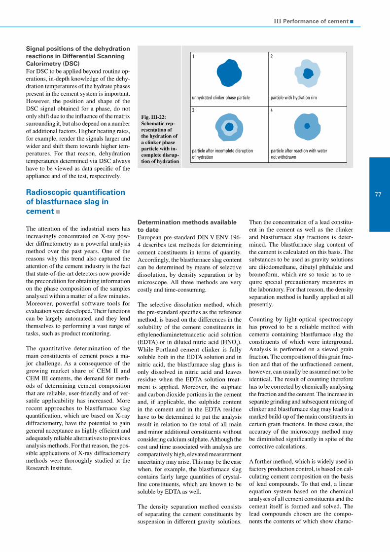
III Performance of cement
77
Signal positions of the dehydration reactions in Differential Scanning Calorimetry (DSC)For DSC to be applied beyond routine op-erations, in-depth knowledge of the dehy-dration temperatures of the hydrate phases present in the cement system is important. However, the position and shape of the DSC signal obtained for a phase, do not only shift due to the influence of the matrix surrounding it, but also depend on a number of additional factors. Higher heating rates, for example, render the signals larger and wider and shift them towards higher tem-peratures. For that reason, dehydration temperatures determined via DSC always have to be viewed as data specific of the appliance and of the test, respectively.
Radioscopic quantification of blastfurnace slag incement
The attention of the industrial users has increasingly concentrated on X-ray pow-der diffractometry as a powerful analysis method over the past years. One of the reasons why this trend also captured the attention of the cement industry is the fact that state-of-the-art detectors now provide the precondition for obtaining information on the phase composition of the samples analysed within a matter of a few minutes. Moreover, powerful software tools for evaluation were developed. Their functions can be largely automated, and they lend themselves to performing a vast range of tasks, such as product monitoring.
The quantitative determination of the main constituents of cement poses a ma-jor challenge. As a consequence of the growing market share of CEM II and CEM III cements, the demand for meth-ods of determining cement composition that are reliable, user-friendly and of ver-satile applicability has increased. More recent approaches to blastfurnace slag quantification, which are based on X-ray diffractometry, have the potential to gain general acceptance as highly efficient and adequately reliable alternatives to previous analysis methods. For that reason, the pos-sible applications of X-ray diffractometry methods were thoroughly studied at the Research Institute.
Fig. III-22: Schematic rep-resentation of the hydration of a clinker phase particle with in-complete disrup-tion of hydration
Determination methods available to dateEuropean pre-standard DIN V ENV 196-4 describes test methods for determining cement constituents in terms of quantity. Accordingly, the blastfurnace slag content can be determined by means of selective dissolution, by density separation or by microscope. All three methods are very costly and time-consuming.
The selective dissolution method, which the pre-standard specifies as the reference method, is based on the differences in the solubility of the cement constituents in ethylenediaminetetraacetic acid solution (EDTA) or in diluted nitric acid (HNO
3).
While Portland cement clinker is fully soluble both in the EDTA solution and in nitric acid, the blastfurnace slag glass is only dissolved in nitric acid and leaves residue when the EDTA solution treat-ment is applied. Moreover, the sulphate and carbon dioxide portions in the cement and, if applicable, the sulphide content in the cement and in the EDTA residue have to be determined to put the analysis result in relation to the total of all main and minor additional constituents without considering calcium sulphate. Although the cost and time associated with analysis are comparatively high, elevated measurement uncertainty may arise. This may be the case when, for example, the blastfurnace slag contains fairly large quantities of crystal-line constituents, which are known to be soluble by EDTA as well.
The density separation method consists of separating the cement constituents by suspension in different gravity solutions.
Then the concentration of a lead constitu-ent in the cement as well as the clinker and blastfurnace slag fractions is deter-mined. The blastfurnace slag content of the cement is calculated on this basis. The substances to be used as gravity solutions are diiodomethane, dibutyl phthalate and bromoform, which are so toxic as to re-quire special precautionary measures in the laboratory. For that reason, the density separation method is hardly applied at all presently.
Counting by light-optical spectroscopy has proved to be a reliable method with cements containing blastfurnace slag the constituents of which were interground. Analysis is performed on a sieved grain fraction. The composition of this grain frac-tion and that of the unfractioned cement, however, can usually be assumed not to be identical. The result of counting therefore has to be corrected by chemically analysing the fraction and the cement. The increase in separate grinding and subsequent mixing of clinker and blastfurnace slag may lead to a marked build-up of the main constituents in certain grain fractions. In these cases, the accuracy of the microscopy method may be diminished significantly in spite of the corrective calculations.
A further method, which is widely used in factory production control, is based on cal-culating cement composition on the basis of lead compounds. To that end, a linear equation system based on the chemical analyses of all cement constituents and the cement itself is formed and solved. The lead compounds chosen are the compo-nents the contents of which show charac-
1 2
3 4
unhydrated clinker phase particle particle with hydration rim
particle after incomplete disruptionof hydration
particle after reaction with waternot withdrawn

VDZ Activity Report 2005 – 2007
78
teristically high or low values, respectively, in one of the cement constituents each. The determination of compositions by means of lead compounds presupposes the separate availability of all cement constituents. For that reason, this method cannot be applied in third-party inspection without some qualification. The correctness of determina-tion results further depends on the accuracy of analysis and on the homogeneity of the constituents.
Blastfurnace slag determination by X-ray diffractometryBlastfurnace slag glass has no ordered crystalline lattice structure. In X-ray dif-fractograms, blastfurnace slag leads to bulging elevations in the background curve at an angle range between about 22 and 38° (2 theta). Sharply defined diffraction peaks are exclusively generated by the crystalline constituents of cement containing blastfur-nace slag. Their intensity thus decreases in favour of the glass hump as the blastfurnace slag portion rises (Fig. III-23).
Although blastfurnace slag glass is amor-phous to X-rays, there are different ways of applying X-ray diffraction to determine the blastfurnace slag portion in Portland-slag and blastfurnace cements systematically and without expending too much effort and cost. One way consists of adding a crystal-line substance as internal standard (“spike”) and evaluating the diffractograms of the mix by Rietveld refinement. This method allows determination of the quantitative phase composition of all crystalline phases taken into account. The sum of all crystal-line phases taken into account during refine-ment always totals 100 mass % in calcula-tion. The blastfurnace slag content can be
determined on the basis of the deviation of the calculated content of internal standard from the actual weighted-in quantity.
The determination by X-ray diffractometry of the blastfurnace slag content can also be effected without adding an internal stand-ard: In this case, the intensity the glass hump contributes to the diffractogram is evaluated directly. This process consists of evaluating and calibrating either absolute X-ray intensity at a reflex-free diffraction angle, or integral background intensity throughout the bulging area. The angle positions at 28.5° and 30.5°(2 theta) turned out to be particularly well suited for evalu-ating absolute intensity. The integral evalu-ation of the glass hump may be effected by integrating an additional, asymmetrical and wide peak in Rietveld assessment, for example. Similar to the evaluation of ab-solute intensity, the peak surface calculated by refinement can be calibrated by a series of appropriate reference samples.
All methods for determining the blast-furnace slag content that are exclusively based on background elevation can only be applied when the glass portion of the blastfurnace slag is constant. When the proportion of crystalline blastfurnace slag constituents, which may for example include merwinite (Ca
3MgSi
2O
8), me-
lilite (Ca2(Mg,Al)(Al,Si)
2O
7) or bredigite
(Ca7Mg(SiO
4)
4), varies, the internal stand-
ard method is advantageous. As the phases mentioned are not present in the clinker component of standardised cements, they are fully assigned to the blastfurnace slag if they are not included in refinement dur-ing evaluation by means of the Rietveld method.
Rietveld refinement using the internal standardLaboratory-made cements with blastfur-nace slag contents of up to 80 mass % were produced from clinker, blastfurnace slag and sulphate agent and compounded with 10 mass % of an internal standard (“spike”) each at the Research Institute of the Cement Industry. For trial purposes, corundum (Al
2O
3), rutile (TiO
2), zirconium
(ZrSiO4), elemental aluminium (Al) und
silicon (Si) were used as spike materials at first in order to investigate the influence of the chemical and granulometric condi-tion of the spike material on the quantifi-cation result. The X-ray diffractograms of the mixes were evaluated by means of the Rietveld method. Based on the crystalline phase contents determined, the blastfurnace slag content that corresponded to the added spike quantity of 10 % was calculated in each case. Fig. III-24 shows the calibra-tion lines obtained when the different spike substances for determining the blastfurnace slag content were used. Regardless of the spike material utilised, the linearity of the correlation between the calculated and the actual blastfurnace slag content is com-paratively good in all cases. The position and the gradient of the calibration line are the only criteria that deviate substantially among the various spikes. Presumably the influences of the spike substance on the calibrating equation that were observed are primarily caused by matrix effects at-tributable to chemically induced absorption in connection with particle size effects. For that reason, homogeneous sample prepara-tion of maximum possible reproducibility must be ensured.
Fig. III-23: Contribution of blastfurnace slag to the background curve in X-ray diffractograms of cements containing blastfurnace slag
Fig. III-24: Comparison of calculated and actual blastfurnace slag contents in cements on the basis of Rietveld evaluation with internal standard – influence of different spike substances
100
80
60
40
20
0
-20
-40
-600 20 40 60 80 100
Eingewogene M.-%
Erre
chne
te M
.-%
Zirkon: R2 = 0,9991
Rutil: R2 = 0,9952
Korund: R2 = 0,9893
Silicium: R2 = 0,9983
Aluminium: R2 = 0,9993
15000
10000
5000
0
Coun
ts
Diffraction angle in (2 Theta)10 20 40 5030
glass hump
diffraction reflexes
80% blastfurnace slag40% blastfurnace slag 0% blastfurnace slag
100
80
60
40
20
0
-20
-40
-600 20 40 60 80 100
Weighted-in mass %
Calcu
lated
mas
s %
zirconium: R2 = 0.9991
rutile: R2 = 0.9952
corundum: R2 = 0.9893
silicon: R2 = 0.9983
aluminium: R2 = 0.9993

III Performance of cement
79
Weighted-inblastfurnace slag
portion
Calibration after Rietveld refinement
based on corundum as internal standard
Calibration afterRietveld refinement based on rutile asinternal standard
Calibration after Rietveld refinement
based on zirconium as internal standard
Calibration afterRietveld refinement based on aluminium as internal standard
Calibration after Rietveld refinement based on silicon as internal standard
10.0 8.8 11.4 9.2 10.1 11.5
20.0 20.3 16.5 20.7 19.5 15.8
40.0 41.6 42.1 38.9 41.0 39.7
60.0 60.5 60.4 60.2 58.9 60.1
80.0 78.8 79.5 80.2 80.4 80.4
Mean deviation 0.96 1.58 0.61 0.62 1.30
Table III-9 lists the results obtained when the blastfurnace slag content was determined by calculation on the basis of calibrated measurements with the spikes used. Deviations averaging between 0.62 and 1.58 mass % were obtained for the results with different spikes. These values range within the same order of magnitude as the accuracies of the traditional test methods. Accordingly, the method of Riet- veld refinement with internal standard can be applied with all cements containing blastfurnace slag in principle, provided that their complete crystalline phase composi-tion is known. Crystalline phases not taken into account are assigned to the blastfur-nace slag portion and can therefore lead to measuring inaccuracies if they are not part of the blastfurnace slag itself.
Quantification based on intensity contribution to the background curveAfter being produced by mixing Portland cement and blastfurnace slag, a further series of calibration samples was analysed by X-ray diffractometry. The glass hump was evaluated by adapting an additional individual peak of large width as part of Rietveld refinement. As the position of the gravity centre of the background bulge is identical with all known blastfurnace slags, a fixed angle position of 31.0° (2 theta) was assumed for the additional peak. The integral evaluation of the surface under the glass hump yielded a linear depend-ence of the glass hump surface on the blastfurnace slag content that covers the entire range of standardised blastfurnace slag cements (Fig. III-25). The evalua-
Table III-9: Comparison of the X-ray diffractometric determination of blastfurnace slag by Rietveld refinement and addition of an internal stand-ard with the weighted-in portions (given in mass %)
Weighted-in quantityCalibration of the
integral intensity of the glass hump
Calibration ofabsolute intensityat 28.5° (2 theta)
Calibration ofabsolute intensityat 30.5° (2 theta)
10.0 11.7 11.6 10.2
15.0 14.6 14.9 15.9
25.0 23.7 23.7 25.1
35.0 33.7 34.4 33.1
65.0 64.5 62.8 64.5
80.0 81.9 81.9 80.8
Mean deviation 1.20 1.28 0.73
Table III-10: Comparison of the X-ray diffractometric determination of blastfurnace slag by evaluating the integral intensity of the glass hump and by calibrating gross intensity at 28.5and 30.5° (2 theta) with the weighted-in portions (given in mass %)
Fig. III-25: Calibration of the surface under the glass hump of the diffractograms of cements with different blast-furnace slag contents
1600
1400
1200
1000
800
600
400
200
0
Coun
ts
0 20 40 60 80
R2 = 0.9985
Weighted-in blastfurnace slag portion in mass %100

VDZ Activity Report 2005 – 2007
80
tion of absolute X-ray intensity at 28.5 and 30.5° (2 theta), respectively, yielded similarly good correlation with R2 values > 0.998 and correspondingly low average deviations (Table III-10).
The additional investigation of a number of samples from different cement works showed, however, that the calibration taken as a basis cannot be transferred to cements of different origin in every case. Fig. III-26 depicts the X-ray diffractograms of a cali-bration series of laboratory-made cements and one factory-made CEM II/B-S 42.5 R the clinker composition of which differed from that of the calibration samples. A blastfurnace slag content of 35.5 mass % in the Portland-slag cement was determined by selective dissolution. The evaluation of absolute X-ray intensity yielded blastfur-nace slag portions of 22.3 mass % at 28.5° (2 theta) and of 23.8 mass % at 30.5° (2 theta). The significant deviation of results from the reference value observed with CEM II/B-S is attributable to absorption effects, which in turn chiefly result from the different chemical composition of the calibration samples and the cements to be determined. The discrepancy in the absorp-tion of X-radiation also becomes evident from the fact that the background curve of the measurements as a whole, i.e. also outside the “glass hump” area, displays deviations. Experience has shown that the absorption effect is less marked in cements with a high blastfurnace slag content than in cements with a high clinker content. One important factor in the investigation of Portland-slag cements in particular there-fore consists of ensuring that the chemical
Fig. III-26: X-ray diffractogram of the factory-made CEM-II/B-S 42.5 R (black) in compari-son with the calibration measurements of the laboratory-made cements (grey)
composition of the clinker component in the calibration samples matches that of the cements analysed as closely as possible.
The investigation results outlined illus-trate that X-ray powder diffractometry is a highly efficient method for determining the blastfurnace slag content in cement. Evaluation can be obtained either via the background elevation (glass hump), or upon addition of an internal standard. All the X-ray diffractometry processes described here allow the achievement of very high accuracy. The internal standard method appears to be particularly suited for third-party inspection as it is largely independent of absorption effects and its accuracy almost exclusively depends on meticulous sample preparation. By con-trast, the methods for direct background determination without use of an internal standard can preferably be applied in fac-tory production control when the material characteristics of the starting materials are largely constant. In addition to involving less effort and fewer costs in preparation, they can be integrated very well into an existing laboratory automation system.
Sulphate resistance
A European standard for the highly sulphate resisting cements also known as HS ce-ments does not yet exist. In most European countries, and also in Germany, however, certain Portland and blastfurnace cements are considered HS cements. According to DIN 1164-10, these are Portland cements with a maximum tricalcium aluminate content of 3 mass % and a maximum alu-
minium oxide content of 5 mass %, as well as blastfurnace cements with a minimum blastfurnace slag content of 66 mass %. The DIN 1045-2 standard specifies that HS cement has to be used in concrete produc-tion in case of a sulphate attack equalling or exceeding 600 mg/l sulphate in the attacking water (exposure class XA2). If the sulphate concentration of the attack-ing water is below 1 500 mg SO
4/l, certain
mixes of cement and hard coal fly ash may be used alternatively.
In Germany, the quick test methods ac-cording to Wittekindt or according to the provisions laid down by the expert com-mittee of the German Institute for Building Technology (SVA method) have tradition-ally been applied to test sulphate resistance behaviour in the laboratory at a temperature of 20 °C. For a couple of years, however, testing has not only been conducted at 20 °C, but at lower temperatures – prefer-ably 5 or 8 °C – as well. The reason behind this is to test resistance to potential harm-ful thaumasite formation, too, which is known to preferably occur at low ambient temperatures. At these low temperatures in particular, the quick tests sometimes did not yield the expected favourable test results for cement/hard coal fly ash mixes that conform to the standard. The discrep-ancy between laboratory observations and building practice experience, according to which no damage has been found to occur in highly sulphate resisting concrete so far, is presumably attributable to two factors. For one thing, the physical impermeability of the structure is insufficient due to high initial porosity. For the other, the sulphate concentration in the laboratory, which is several times higher, may lead to changes in the reaction progress.
Realistic testing conditionsFor about five years now, the Research In-stitute has carried out sulphate resistance tests under realistic conditions in addi-tion to examinations based on quick tests. Substantially, there are three features that distinguish them from the traditional quick tests. For one thing, the sulphate concentra-tion of the attacking medium is limited to 3 000 mg/l or even to as little as 1 500 mg/l, respectively. This corresponds to the limit for exposure class XA2 laid down in DIN 1045-2 and to the limit applicable for the use of cement/fly ash mixes. On the other hand, the water/cement ratio is limited to 0.50. Furthermore, testing is conducted at a lower ambient temperature of 8 °C. Following the usual 14-day preliminary storage at 20 °C, the mortar specimens are
Coun
ts3 200
2 800
2 400
2 000
1 600
1 200
800
400
05,0 10,0 15,0 20,0 25,0 30,0 35,0 40,0 45,0 (2 Theta)
22.3% blastfurnace slag 23.8% blastfurnace slagCEM II/B-S 42.5 R (35.3% blastfurnace slag according to ENV 196-4)Cement and calibration samples from different works

III Performance of cement
81
stored in the test solution for a period of at least six or twelve months, respectively.
Fly ash-free test mortar The realistic test method is to provide for a reliable and clear differentiation between mortars known to be sulphate resisting and mortars that are not sulphate resistant. Mor-tars based on HS cements and various high-aluminate Portland and Portland-limestone cements were produced and investigated for verification purposes. Figs. III-27 and III-28 show flat mortar prisms made from highly sulphate resisting Portland cement and highly sulphate resisting blastfurnace cement after two years of storage. The test specimens are fully intact. Crack formation or spalling has not even occurred at the cor-ners and the edges. By contrast, flat mortar prisms based on Portland-limestone cement and high-aluminate ordinary Portland ce-ment show a different appearance. By way of example, Fig. III-29 depicts a flat mortar
prism made from ordinary Portland cement containing 5 mass % limestone meal as a minor additional constituent. The mor-tar microstructure has suffered obvious damage. The corners and edges have lost cohesion. This is primarily attributable to the formation of thaumasite, which is discernible as a white reaction product. Thaumasite is detected by means of X-ray diffractometry and scanning electron microscopy.
Test mortars containing fly ashFigs. III-30 to III-32 show the test mortars based on 80 mass % cement and 20 mass % hard coal fly ash. The equivalent water/cement ratio was 0.50, and fly ash was offset against the water/cement ratio at a factor of f = 0.4. In all three cases the test specimens were intact after a test duration of two years. Neither expansion nor super-ficial thaumasite formation were found to have occurred. Just like Portland cements
Fig. III-27: Flat mortar prism made from highly sulphate resisting Portland cement (CEM I 32.5 R – HS) after 24-month storage in sodium sulphate solution (1 500 mg SO4/l) at 8 °C
Fig. III-28: Flat mortar prism made from highly sulphate resisting blastfurnace cement (CEM III/B 32.5 R–LH/HS) after 24-month storage in sodium sulphate solution (1 500 mg SO4/l) at 8 °C
Fig. III-29: Flat mortar prism made from Portland cement(CEM I 32.5 R containing 5 mass % limestone meal as a minoradditional constituent) after 24-month storage in sodium sulphate solution (1 500 mg SO4/l) at 8 °C
Fig. III-30: Flat mortar prism made from a mix consisting of80 mass % CEM I 32.5 R and 20 mass % CFA (k = 0.4) after 24-month storage in sodium sulphate solution (1 500 mg SO4/l) at 8 °C
Fig. III-31: Flat mortar prism made from a mix consisting of80 mass % CEM II/A-LL 32.5 R and 20 mass % CFA (k = 0.4) after24-month storage in sodium sulphate solution (1 500 mg SO4/l)at 8 °C
Fig. III-32: Flat mortar prism made from a mix consisting of80 mass % CEM II/B-M (S-LL) 32.5 R and 20 mass % CFA (k = 0.4) after 13-month storage in sodium sulphate solution (1 500 mg SO4/l) at 8 °C
and Portland-limestone cements, Portland-composite cements mixed with fly ash may be applied to produce concrete exposed to sulphate attacks of up to 1 500 mg SO
4/l.
The sulphate resistance test of Portland-composite cements carried out for the first time at the Research Institute consisted of investigating two cements of the most com-mon type CEM II/B-M (S-LL). The high sulphate resistance of the mixtures was not only confirmed by testing at 1 500 mg SO
4/l, but also at a sulphate concentration
of 3 000 mg SO4/l. The investigation results
available for Portland-composite cements so far cover an exposure period of just over one year. Investigations will be continued over the next years.

VDZ Activity Report 2005 – 2007
82 Quality surveillance and quality assurance of cement
IV
Production of standard mortar for strength testing
The quality surveillance and quality assurance of cement form part of the traditional functions of the VDZ’s quality surveillance organisation. Regular audit testing of the building material cement was begun – by the VDZ’s precursor organisation back then – as early as more than 100 years ago. It was the cement manufacturers themselves who took the initiative for this measure. Building supervisory authorities did not adopt this idea and specify mandatory provisions for product inspection until much later.
The transformation in character that the quality surveillance organisation underwent over the past ten to 15 years was chiefly at-tributable to the continuous changeover to European regulations. The European cement standard has been effective for about five years now. Products labelled with the CE marking can be traded freely throughout Europe. Questions regarding the comparabil- ity of conformity assessment at European level have increasingly taken centre stage now. In this context, it is not only European approval by the EU Commission according to the Construction Products Directive that has gained in importance, but also ac- creditation under private law, which serves as proof of competence and as a confidence-building measure. The revision of the New Approach will entail changes in this field in the future. The quality surveillance organisation braced for this development early on, obtaining accreditation under private law in addition to recognition in the domain regulated by law.
The number of binders certified and inspected hardly changed in the period under review. Some 528 binders from 62 works were inspected in accordance with statutory regulations in 2007. This figure does not include multiple certificates for identical binders. The number of binders additionally inspected according to regulations under private law in compliance with agreements concluded with foreign bodies increased slightly again. The materials further inspected included pigments, fly ashes and grouts. The areas of approval were extended slightly in the period under review.
Activities in the field of cement standardisation were continued consistently with the involvement of Research Institute employees. Further product and conformity evaluation standards for special cements and special binders in particular were added. During the period under review, the CEN enquiry process on amending the standards for sulphate resisting cements was conducted. Further-more, the revision of the two basis standards – product standard EN 197-1 and conformity evaluation standard EN 197-2 – has been initiated by now. Conformity evaluation standard EN 197-2 and the associated guidelines now also serve as a model for corresponding rules governing the conformity evaluation of additions. Moreover, corresponding interpretations of the regulations for conformity evaluation were established and put in effect at notified body level. The methods of testing cement were also advanced in the period under review. The work regarding the European method of chromate testing required especially intense supervision.

IV Quality surveillance and quality assurance of cement
83

VDZ Activity Report 2005 – 2007
84
The VDZ’s quality surveillance organisation
The testing, inspection and certification of cements and cement-type binders to meet the protective goals set by the state building regulations or according to the Construc-tion Products Law are some of the VDZ’s constitutional functions. For this purpose the association operates the quality surveil-lance organisation as a testing laboratory, inspection body and certification body (PÜZ body). The technical committee of the VDZ’s quality surveillance organisation discusses the results of third-party inspec-tion twice a year.
Cements have been certified in compliance with the European cement standard EN 197-1 for about five years. These cements are labelled with the CE marking and can be traded freely in all the states of the European economic area. European regu-lations now apply to further construction products inspected by the VDZ’s quality surveillance organisation, such as masonry cements. Basically, also all cements with special properties according to DIN 1164-10 meet the requirements of European cement standard EN 197-1. Accordingly, more than 90% of the work performed by the VDZ’s quality surveillance organisation now relates to European regulations. Thus, questions regarding the comparability of conformity assessment at European level have increasingly taken centre stage.
Approval and accreditationThe VDZ’s quality surveillance organisation exercises its functions as a testing labora- tory, inspection body and certification body in the domain regulated by law. Ap-proval covers the state building regulations (LBO) on the one hand, which are appli-cable at national level. Within the scope of the state building regulations, conform-ity is indicated by the national Ü mark (Fig. IV-1). Moreover, the VDZ’s qual-ity surveillance organisation is notified according to the German Construction Products Law, which implements the EU Construction Products Directive, and is registered in Brussels as certification body No. 0840. Within the scope of the Con-struction Products Directive, the CE mark-ing is attached to indicate conformity. In addition to that, bilateral agreements exist with foreign bodies. Corresponding marks under private law (Fig. IV-1) are used to attest conformity.
Fig. IV-1: National and European conformity marks and other marks for cement
Construction products Technical regulation(s)Conformity
attestation level
BPG LBO
Binders
– common cement EN 197-1 1+
– cement with special properties EN 197-4 1+
EN 14216 1+
DIN 1164-10, -11, -12 ÜZ
– calcium aluminate cement EN 14647 1+
– masonry cement EN 413-1 1+
– hydraulic road binder DIN 18506 (ÜZ)1)
– building lime EN 459-1 2
– other cement-type binders (incl. sprayed concrete cements)
Approval2) ÜZ
Concrete additions
– pigments EN 12878 2+
– fly ash EN 450-1 1+
– silica fume EN 13263-1 1+
– natural pozzolana (trass) DIN 51043 ÜZ
– other concrete additions Approval2) ÜZ
Concrete admixtures
EN 934-2, -3, -4 2+
DIN V 18998 ÜHP
Approval2) ÜZ
Aggregates
EN 12620 2+
EN 13055-1 2+
EN 13139 2+
Masonry mortar
EN 998-2 2+
Grouting mortar
EN 447 ÜZ
BPG: Construction products law LBO: State building regulations ÜZ: Conformity certificate
1) not relevant in building authority terms, attestation level corresponds to ÜZ2) if production process, composition or properties deviate substantially from the standard
Table IV-I: Areas where the VDZ’s quality surveillance organisation is approved as a testing laboratory, inspection body and certification body for construction products
marks under private law
BENOR
statutory marksnational European
D NL B F DK1)
1) VDZ membership mark

IV Quality surveillance and quality assurance of cement
85
Beyond the requirements deriving from the domain regulated by law, the VDZ’s quality surveillance organisation has additionally been accredited as a product certification body under private law according to EN 45011 since 2002. In addition to that, all relevant laboratory tests were accredited in accordance with ISO 17025. Under the terms of accreditation, the quality surveil-lance organisation is frequently appraised by third-parties (see Chapter VDZ/FIZ).
Notification of the VDZ’s quality sur-veillance organisation by the competent building supervisory authorities primarily covers cements and cement-type binders. It further includes concrete additions and admixtures as well as cementitious mix-tures and relates to products governed both
Binder Standard/regulation ScopeType of
certificationCertification
bodyInspection
bodyNumber of
bindersNumberof works
Cement
EN 197-1 EU
StatutoryVDZ
VDZ 5611) 62DIN 1164 Germany
Technical Approval Germany
DIN 1164 Germany others 1 1
ZTV Beton Germany - VDZ 57 34
BRL 2601, NEN 3550 Netherlands
Under private law
bmc VDZ 108 30
TRA 600, PTV 603, NBN B 12
Belgium VDZ VDZ 34 13
Reglement NF France AFNOR VDZ 24 10
Masonrycement
EN 413 Germany Statutory VDZ VDZ 22 18
BRL 2603 Netherlands Under private law bmc VDZ 4 3
Hydraulicroad binder
DIN 18506 Germany (statutory) VDZ VDZ 13 12
1) these figures include a total of 68 multiple certificates for identical cements as well as 20 cements with building inspectorate approval
by standards and by technical approvals (Table IV-1). In order to offer a highly attractive service range, the areas of ap-proval are continually updated. An applica-tion for approval to be extended to include calcium aluminate cement according to EN 14647, fly ash according to EN 450, silica fume according to EN 13263 and pigments according to EN 12878 was again filed in the period under review.
Third-party inspection of cement according to statutory regulationsTable IV-2 presents an overview of the cements and hydraulic binders that the VDZ’s quality surveillance organisation certified and inspected, respectively, in the year 2006. 596 binders were certified and inspected in accordance with statutory
Table IV-2: Overview of the cements and hydraulic binders inspected and certified by VDZ’s quality surveillance organisation in 2006
regulations. Totalling 561 (94%), cements accounted for the largest share. The figures also include nine cements from six foreign works. In 68 of 561 cases, multiple cer-tificates were issued for identical cements which obtained certificates of conformity both according to EN 197-1 and according to DIN 1164-10. In one case, the VDZ’s quality surveillance organisation issued a certificate of conformity according to DIN 1164 for a cement audited by a foreign inspection body.
A total of 528 binders from 62 works was inspected in 2006. This figure does not in-clude the multiple certificates for identical cements. The number of binders audited thus remained largely constant over the past eight years (Fig. IV-2). The average
Fig. IV-3: Average number of binders inspected per works for the works inspected by VDZ’s quality surveillance organisation
Fig. IV-2: Trend of binders and works audited by VDZ’s quality surveillance organisation
600
560
520
480
440
400
360
320
90
85
80
75
70
65
60
551979 1981 1983 1985 1987 1989 1991 1993 1995 1997 1999 2001 2003 2005
Year2007
Num
ber o
f bin
ders
Num
ber o
f bin
ders
bindersworks
10
8
6
4
2
01979 1981 1983 1985 1987 1989 1991 1993 1995 1997 1999 2001 2003 2005
Year2007
Num
ber o
f bin
ders
per
wor
ks

VDZ Activity Report 2005 – 2007
86
number of binders inspected per works has been rising for about 20 years and averages approx. 8.5 binders per works at present (Fig. IV-3).
Table IV-3 summarises the number of cer-tificates (also without multiple certificates for identical cements) for domestically produced cements inspected by the VDZ’s quality surveillance organisation as well as the corresponding domestic dispatch quan-tities for 2006 compared to 2004 (figures in brackets). The cements were graded in the main cement types CEM I, CEM II, CEM III, CEM IV and CEM V, and the strength classes 32.5, 42.5 and 52.5. The table shows that the number of domestic cements inspected has increased by 41 to 484 since 2004. Portland-composite ce-ments of strength classes 42.5 and 52.2 as well as blastfurnace cements of strength class 42.5 accounted for the largest share of the increase. It is notable that the increase was exclusively restricted to cements with ordinary early strength (N).
The dispatch quantity of Portland-compos-ite cements CEM II containing blastfurnace slag and blastfurnace cements CEM III rose significantly as well. The dispatch quantity share of Portland cements CEM I of strength classes 32.5 and 42.5 declined at the same time. The marked shift in the share in dispatch quantities away from the cements of strength class 32.5 R towards the cements of strength class 42.5 N was notable as well.
Table IV-3: Number of domestic cements inspected by VDZ’s quality surveillance organisation in 2006 (2004)
CementNumber of cements Share in (domestic) cement dispatch in mass %
32.5 42.5 52.5 Total 32.5 42.5 52.5 Total
Portland cement CEM I 51 (59) 80 (81) 56 (54) 187 (194) 12.3 (23.0) 21.5 (28.3) 8.3 (7.3) 42.1 (58.6)
Portland-composite cement CEM II
79 (80) 60 (41) 31 (14) 170 (135) 24.0 (22.1) 12.4 (7.5) 3.6 (1.4) 40.0 (31.0)
Blastfurnace cement CEM III 72 (75) 44 (30) 7 (6) 123 (111) 9.9 (8.3) 7.5 (1.9) 0.5 (0.2) 17.9 (10.4)
Pozzolanic cement CEM IV 3 (2) - (-) - (-) 3 (2) 0.0 (0.0) - (-) - (-) 0.0 (0.0)
Composite cement CEM V - (-) - (-) 1 (1) 1 (1) - (-) - (-) 0.0 (0.0) 0.0 (0.0)
Total 205 (216) 184 (152) 95 (75) 484 (443) 46.2 (53.4) 41.4 (37.7) 12.4 (8.9) 100.0 (100.0)
Cements with high early strength (R)
124 (132) 102 (97) 50 (45) 276 (274) 37.0 (44.7) 27.6 (30.9) 8.5 (7.4) 73.1 (83.0)
Cements with ordinary early strength (N)
81 (84) 82 (55) 45 (30) 208 (169) 9.2 (8.7) 13.8 (6.8) 3.9 (1.5) 26.9 (17.0)
Cements with specialproperties (LH, HS, NA)
60 (65) 45 (33) 6 (5) 111 (103) No information
57 cements approved for use in concrete pavements were inspected in 2006 as well. The VDZ’s quality surveillance organisa-tion further inspected 22 masonry cements to EN 413-1, four of which were assigned to class MC 12.5, and 13 hydraulic road binders to DIN 18506 in 2006.
Fig. IV-4 confirms the marked shift in the domestic dispatch of cements that took place over the past years. It lists the share of cement types and strength classes in do-mestic dispatch recorded in 2000 opposite the corresponding figures for 2006. For one thing, it becomes evident that the share of cements of strength class 32.5 declined from 60.1% to 46.2% over the past six years, and that cements of higher strength classes recorded corresponding gains at the same time. By now, the output of cements of strength class 42.5 almost equals that of strength class 32.5 cements.
At the same time, a similar shift was re-corded with the cement types. In the wake of stepped-up efforts to reduce CO
2 and
utilise blastfurnace slag as a cement con-stituent, the share of Portland cements in dispatch quantities nearly halved over the past 20 years. It has declined from 61.7% to 42.1%, or by nearly 20%, respectively, since 2000. The share of CEM II cements simultaneously grew at the same rate. This development was particularly notable with the cements of strength class 32.5, in which CEM II cements account for more than half of the cements by now. The share of
CEM III cements edged down in the period under review.
Third-party inspection of cement according to voluntary regulationsBilateral agreements between the VDZ’s quality surveillance organisation and the corresponding Belgian, French and Dutch inspection bodies on the mutual recogni-tion of testing, inspection and certification activities have existed for many years. They relate to third-party inspection ac-cording to voluntary regulations beyond the scope stipulated by law (Fig. IV-1). The VDZ’s quality surveillance organisa-tion performs the supplementary tests and inspections required at the German manu-facturers’ sites upon consultation with the corresponding foreign body. This reduces the additional costs accruing for cement manufacturers.
The VDZ’s quality surveillance organisa-tion is currently inspecting 108 cements and four masonry cements from 30 works in accordance with Dutch evaluation crite-ria (BRL) additionally; the certificates are issued by BMC (Table IV-2).
Furthermore, the VDZ’s quality surveil-lance organisation is currently certifying and inspecting 34 cements from 13 works according to Belgian regulations addition-ally, thus creating the basis for the Belgian BENOR marking being attached. The Bel-gian regulations underwent some adjust-ments in the period under review, which

IV Quality surveillance and quality assurance of cement
87
included more precise provisions regarding clinker changes.
There are regulations governing the issu-ance of the NF marking in France. The agreement concluded with the French certification body AFNOR holds that the VDZ’s quality surveillance organisation should perform audit testing and works visits at German cement works as a sub-contractor of AFNOR. The quality surveil-lance organisation is currently testing and inspecting 24 cements labelled with the NF mark from ten works.
In the period under review, individual agreements on the recognition of inspec-tion results were also concluded with the Danish certification body Dancert. They chiefly related to the inspection of the chro-mate content according to EN 196-10.
Further construction productsAfter the new pigment standard EN 12878 had been adopted by the building supervi-sory authorities in 2006, the VDZ’s quality surveillance organisation also certified and inspected the factory production control of pigment manufacturers. In the period under review, this covered the manufacture of 37 different pigments in Germany. More-over, 54 pigment samples were tested in the quality surveillance laboratory.
Following the adoption of the new masonry mortar standard EN 998-2, CE markings can also be issued for masonry mortar manufacturers. To this end, the factory pro-duction control (conformity assessment 2+)
Fig. IV-4: Comparison of the share in the domestic dispatch of cements manufactured in Germany that the cement types and strength classesaccounted for in the years 2000 and 2006
of masonry mortar manufacturers has to be approved and inspected by notified bodies. Instructions on factory production control as required for the CE marking of masonry mortars following suitability testing are included in the new DIN 18581. Research Institute employees were involved in the elaboration of this standard as well. DIN 18581 will be adopted in the year 2008.
The inspection of grout injection at con-struction sites was started in November 2006. Moreover, contract testing on grout according to EN 447 was performed in the period under review.
Proficiency testingThe testing laboratory of the VDZ’s quality surveillance organisation takes part in sev-eral regular inter-laboratory tests to ensure a constant testing performance and to com-ply with the corresponding specifications deriving from standards or accreditation, respectively. The standard tests for cement in particular are compared several times a year at national and international level.
Stichting BMC for example organises weekly proficiency tests of a Dutch refer-ence cement that are evaluated four times a year. The representatives of the third-party inspection bodies participating discuss the results at a meeting held annually. At the same time, the results obtained by the weekly testing of the reference cement are documented on a quality control card in order to detect variations and be able react to them quickly.
The Research Institute also participates in the cement proficiency testing carried out every year by the Association Technique de l’Industrie des Liants Hydrauliques (ATILH), in which some 200 test labora-tories from 59 countries regularly take part. Similar national inter-laboratory tests were conducted on other building materials, such as fly ash and concrete admixtures.
The VDZ also participates in the inter-laboratory tests frequently organised by the standardisation committees in conjunction with the revision of testing standards (cf. section on methods of testing below). This serves to test the methods, detect possible weak points, and derive statistic data on the repeatability and reproducibility of the methods.
Testing laboratoryEvery year, the laboratories of the Research Institute test about 3 500 binder samples as part of audit testing as well as the as-sociated contract testing and proficiency testing. Given an average of approximately 10 properties to be tested, this amounts to some 35 000 individual tests. Given such a high sample throughput, efficient test pro-cesses are essential on the one hand; on the other hand, a consistent standard and high quality of testing must be ensured. This is accomplished by high degree of standard-isation of testing procedures. Physical test-ing is carried out at the quality surveillance laboratory (Fig. IV-5), while chemical tests are performed by the cement chemistry department acting as a subcontractor. In accordance with the European standard for
32.5 N; 32.5 R
46.2 %
12.3 % 3.6 %
41.4 %
24.0 %
42.5 N; 42.5 R 52.5 N; 52.5 R
21.5 %
12.4 %9.9 %
7.5 %CEM II
8.3 % 0.5 %
12.4 %
CEM III
CEM II
CEM IIICEM II
CEM I
60.1 %
29.2 %
0.8 %
33.3 %
18.9 %
26.9 %
4.2 %12.0 %2.2 %
CEM III CEM II
5.6 %
CEM I
0.2 %
6.6 %
CEM III
32.5 N; 32.5 R 42.5 N; 42.5 R 52.5 N; 52.5 R
2000 2006
CEM I
CEM I
CEM II
CEM III
CEM I
CEM II
CEM III CEM I

VDZ Activity Report 2005 – 2007
88
LH cements, the number of heat of hydra-tion measurements was increased from two to six per year in the period under review, and the test procedure laid down in the new version of EN 196 was adopted.
Quality assurance
The EU Construction Products Directive is one of a total of 25 directives according to the so-called New Approach, which was passed in 1985. It constitutes a simplifying legal instrument aimed at creating a harmo-nised European single market. Following a revision of the New Approach initiated about three years ago, the Commission submitted the first proposals for revision in the period under review. The interested parties were notified of the changes to come in several information events.
Fig. IV-5: Viewinto the quality surveillancelaboratory
ment in the fields of conformity evaluation and accreditation is to be outlined briefly below.
Conformity evaluationThe conformity evaluation process for the respective building materials is specified by the EU Commission and defined in the associated harmonised standard by CEN. The Construction Products Directive lays down four systems of conformity attesta-tion (Table IV-4). These four systems do not completely conform to the conformity assessment modules provided for in the New Approach, but can be derived from them. It cannot yet be predicted at present whether the revision of the Construction Products Directive will entail any modifi-cations in this respect.
A feature all conformity assessment sys-tems have in common is the fact that the manufacturers themselves are responsible for carrying out factory production control. The respective standards specify the attes-tations to be submitted by the manufacturer as well as the tests to be conducted, also stipulating the methods and frequency of testing. For many building materials, the scope of the tests to be performed under the terms of factory production control grew in the wake of harmonised standards being adopted. The four conformity attesta-tion systems differ in terms of the degree to which an independent external body is involved in conformity evaluation.
With most construction products, manufac-turers have to issue a declaration of con-formity. The approved body either inspects factory production control (system 2+) or conducts initial type-testing on the product (system 3). System 4 does not provide for an external body being involved. Regular audit testing is carried out in the case of product certification (system 1+) only.
Product certification by an approved body is stipulated for a small number of build-ing materials only. Given their importance for safe construction, these include cement and reactive concrete additions. In the period under review, conformity evalu-ation standards for fly ash, silica fume and blastfurnace slag, among other standards, were drawn up and adopted. The cement conformity evaluation standard EN 197-2 served as a model for these documents.
The cement conformity evaluation standard EN 197-2, which is six years old by now, was revised in the period under review. As the experience gathered with this standard was very favourable, it was chiefly neces-
Elements of conformity controlSystems according to the
Construction Products Directive
1+ 1 2+ 2 3 4
Man
ufac
ture
r Initial type-testing of the product
Testing of samples taken at the factory according to a prescribed test plan
Factory production control
App
rove
d bo
dy
Initial type-testing of the product
Audit testing of samples taken at the factory
Initial inspection of the factory and of factory production control
Continuous surveillance, assessment and approval of factory production control
CertificationDeclaration by
the manufacturer
Table IV-4: Systems of conformity attestation according to the Construction Products Directive and associated conformity control instruments
In the next step, the EU Construction Prod-ucts Directive is to be adapted and revised. In the EU Commission’s opinion, the Con-struction Products Directive lifts only part of the trade barriers. More importantly, it is considered too complex, and its specifica-tions are deemed equivocal. In the period under review the EU Commission conduct-ed two enquiries to gather proposals for the revision of the Construction Products Directive. Some countries are therefore trying to work towards its simplification and deregulation. Certain modifications will presumably result from the revision of the New Approach.
The conformity assessment modules, ac-creditation, market surveillance and CE marking were taken into account when the New Approach was revised. The develop-

IV Quality surveillance and quality assurance of cement
89
sary clarifications that were effected. The modifications implemented related to the definition of the term factory, to the se-quence of certification (Fig. IV-6), to the procedure in the case of non-conformity of factory production control, to the re-quirements placed on dispatching centres, to audit testing during the initial period, to the statistical evaluation of test results, to sampling and testing details, and to conformity marking, among other items. TC 51 specified that the standard was to be adopted as a European standard in ac-cordance with the Unique Acceptance Pro- cedure (UAP) and the existing guidelines for EN 197-2 were to be revised as well.
Accreditation and approval The revision of the New Approach will have far-reaching consequences for the structure of the German accreditation domain. There have been calls for an in-creased harmonisation of the boundary conditions for approved bodies at Euro-pean level. In Germany, some 200 bodies are currently notified in conformity with the Construction Products Directive. This figure is considerably higher than in other EU countries. Increasing demands for ac-creditation under private law being applied as the criterion for evaluating the compe-tence of independent bodies in the future have been voiced in foreign countries in particular. In this way, comparable condi-tions are to be created for all accreditation bodies throughout Europe.
An extensive study on “Conformity evalu-ation in Germany” that had been conducted on behalf of the Federal Ministry for Eco-nomic Affairs (BMWi) was submitted in 2006. The study reaches the conclusion that, taking into account the European trends, there is need for action to the effect that the accreditation system currently in place in Germany should be reconsidered. The proposal to set up one single German accreditation body was made. The BMWi will suggest a concept as a transitional solution until a corresponding European regulation is available. For that reason, a German accreditation advisory board was founded to advise and support the BMWi. It is made up of 21 voting members from the interested parties, who also include a nucleus of accreditation bodies. The build-ing sector has hardly been represented up to now.
Fig. IV-6: Sequence of conformity certification of cement
The search for a harmonised solution will presumably take several years. The future structure is not discernible yet either. The future interface of the areas covered and not covered by statutory regulations, respec-tively, will be important in particular.
Cooperation of notified bodiesProducts labelled with the CE marking may be put on the market throughout Europe. For that reason, it is important that all noti-fied bodies in Europe interpret regulations uniformly and work under comparable conditions. The EU Commission therefore demands that all approved bodies in Europe take part in a regular exchange of opinions, which the bodies themselves organise. For that reason, various panels were set up at European level. As the number of bodies in
Germany is so large, national panels mir-roring the European ones have been estab-lished additionally. The Research Institute is represented on the relevant panels.
The Research Institute is involved in sector group SG 02 “Cement, concrete, mortar, aggregates” of the product-related sector groups. SG 02 elaborates position papers on the inspection of concrete constituents as well as masonry and repair mortars. In the period under review, position papers on the inspection of cement, fly ash, silica fume and building lime, among other pa-pers, were drawn up. In addition to that, there is an advisory group that discusses and adopts the corresponding superordinate and horizontal papers. It further debates general questions relating to the coopera-
ACT: autocontrol testingAT: audit testingFPC: factory production controlWQM: works quality manual
Initial inspection of thefactory and FPC
Verification: WQM complieswith requirements
Manufacturer applies for certification
New factory?
Particular inspectionnecessary?
yes
Corrective action pro-posed by manufacturer
no
no
no
Issue thecertificate
ACT and ATduring initial
period
non-conforming
conforming
no
yes
yes
yes
Verification: Plants/laboratorycomply with requirements
Arrange for AT sampling,plan the initial period
First AT: results conformto requirements?
Evaluationof ACT/AT
Cancelthe certificate
Certificate remainsvalid
Initial inspection:are requirements
met?
Corrective action pro-posed by manufacturer
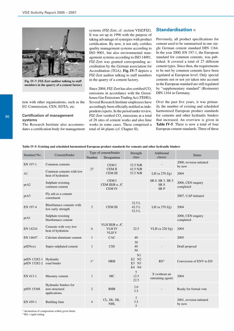
VDZ Activity Report 2005 – 2007
90
tion with other organisations, such as the EU Commission, CEN, EOTA, etc.
Certification of management systemsThe Research Institute also accommo-dates a certification body for management
Fig. IV-7: FIZ-Zert auditor talking to staff members in the quarry of a cement factory
Standard No. Cement/binderType of cement/binder Strength
classAdditional
classesStatus
Number Designation
EN 197-1 Common cements
27CEM I CEM II CEM III
32.5 N/R 42.5 N/R 52.5 N/R
-2000, revision initiatedby now
A1Common cements with low heat of hydration
LH (≤ 270 J/g) 2004
prA2Sulphate resisting common cement
CEM I CEM III/B u. /C
CEM IV
SR 0. SR 3. SR 5 SR S SR P
2006, CEN enquirycompleted
prA3Fly ash as a cementconstituent
2007, UAP initiated
EN 197-4Blastfurnace cements with low early strength
3 CEM III32.5 L 42.5 L 52.5 L
LH (≤ 270 J/g) 2004
prA1Sulphate resisting blastfurnace cement
2006, CEN enquirycompleted
EN 14216Cements with very lowheat of hydration
6VLH III/B u. /C
VLH IV VLH V
22.5 VLH (≤ 220 J/g) 2004
EN 14647 Calcium aluminate cement 1 CAC 40 - 2005
prENxxx Super-sulphated cement 1 CSS30 40 50
- Draft proposal
prEN 13282-1 prEN 13282-2
Hydraulicroad binder
11) HRB
N1 E2 N2 E3 N3 E4 N4
RS2) Conversion of ENV to EN
EN 413-1 Masonry cement 1 MC5
12.5 22.5
X (without airentraining agent)
2004
prEN 15368Hydraulic binders fornon-structuralapplications
2 BHB2.0 3.5
- Ready for formal vote
EN 459-1 Building lime 4CL. DL. HL.
NHL
2 3.5 5
2001, revision initiatedby now
1) declaration of composition within given limits2) RS = rapid setting
systems (FIZ-Zert, cf. section VDZ/FIZ). It was set up in 1996 with the purpose of taking advantage of synergies with product certification. By now, it not only certifies quality management systems according to ISO 9001, but also environmental man-agement systems according to ISO 14001. FIZ-Zert was granted corresponding ac-creditation by the German association for Accreditation (TGA). Fig. IV-7 depicts a FIZ-Zert auditor talking to staff members in the quarry of a cement factory.
Since 2004, FIZ-Zert has also certified CO2
emissions in accordance with the Green-house Gas Emissions Trading Act (TEHG). Several Research Institute employees have accordingly been officially notified as inde-pendent experts. In the period under review, FIZ-Zert verified CO
2 emissions at a total
of 28 sites of cement works and also lime works in some cases. These comprised a total of 44 plants (cf. Chapter II).
Standardisation
Previously, all product specifications for cement used to be summarised in one sin-gle German cement standard DIN 1164. In the year 2000, EN 197-1, the European standard for common cements, was pub-lished. It covered a total of 27 different cement types. Since then, the requirements to be met by common cements have been regulated at European level. Only special cements not or not yet taken into account in the European standard are still regulated by “supplementary standard” (Restnorm) DIN 1164 in Germany.
Over the past five years, it was primar- ily the number of existing and scheduled harmonised European product standards for cements and other hydraulic binders that increased. An overview is given in Table IV-5. There is now a total of four European cement standards. Three of these
Table IV-5: Existing and scheduled harmonised European product standards for cements and other hydraulic binders

IV Quality surveillance and quality assurance of cement
91
“sulphate resisting”. The family of sulphate resisting common cements is subdivided into a total of seven different products (Tables IV-6 and IV-7). Five subclasses are formed by indicating a number or a letter after “SR”. These subclasses allow the pur-poseful selection of SR cements for certain national application conditions.
There was no doubt that CEM III/B and CEM III/C cements were to be considered sulphate resisting without any restric-tions. In this respect, the draft standard is identical with the specifications currently applicable in Germany. These cements are identified as “SR”.
standards comprise specifications for ce-ments with low heat of hydration (LH and VLH). A standard on calcium aluminate cement was added in the period under review, and a standard on super-sulphated cement is being prepared. Three further standards relate to hydraulic binders, and another one to building lime. Some of the standards have been or are being extended by amendments (EN 197-1 and EN 197-4) or by the inclusion of new classes (e.g. hy-draulic road binders). Cements and binders that are of regional importance only have now been incorporated into standardisation as well (e.g. hydraulic binders for non-structural purposes).
Regardless of the extension of the product standards, the fact that, combined with the associated conformity evaluation standard 197-2 (see section above) and the associ-ated testing standards (see section below), basis standard EN 197-1 provides a com-plete product description of the building material cement has been confirmed over the past five years. This set of standards has thus undoubtedly proved its worth.
The Research Institute is represented on al-most all CEN/TC 51 standardisation com-mittees. The activities associated with the extension and revision of basis standard EN 197-1 will be outlined briefly below.
Sulphate resisting cementsThe EU Commission has pressed for har-monising the specifications for sulphate resisting cements at European level for many years. Endeavours made over many years have not met with success so far. Among other reasons, this is attributable to the fact that a performance test method for sulphate resisting cements that is generally applicable and lends itself to the elabora-tion of a performance-oriented product standard is not available to date. A CEN report summarising the status was submit-ted and adopted at the annual meeting of the European Standards Committee TC 51 held in Dresden last year.
The search for a European compromise was therefore continued on the basis of prescrip-tive criteria. A report on the sulphate resist-ing cements standardised in Europe served as an input variable. In the period under review, one amendment regarding sulphate resisting cements was drawn up each for EN 197-1 and EN 197-4, and the CEN enquiry procedure was implemented.
In accordance with the amendments to the standard proposed, sulphate resisting ce-ments are identified by the letters “SR” for
Main types
Designation of the five products (types of sulphate resisting
common cement)
Composition in mass %
Main constituentsMinor
additional constitu-
ents
Clinker
K
Blast-furnace
slag
S
Natural pozzo-
lana
P
Sili- ceous fly ash
V
CEM I
Sulphate resisting Portland cement
CEM I…-SR 0CEM I…-SR 3CEM I…-SR 5
95-100 - - - 0-5
CEM III
Sulphate resisting blast-furnace cement
CEM III/B…-SR 20-34 66-80 - - 0-5
CEM III/C…-SR 5-19 81-95 - - 0-5
CEM IV
Sulphate resisting pozzolana cement
CEM IV/A…-SR 65-80 20-35 0-5
CEM IV/B…-SR 45-64 36-55 0-5
Table IV-6: The seven products intended for the family of sulphate resisting commoncements
PropertyTesting acc.
toCement type Strength class Requirements
Sulphatecontent (as SO
3)
EN 196-2
CEM I…-SR 0CEM I... -SR 3CEM I…-SR 5CEM IV/A…-SR CEM IV/B…-SR
32.5 N 32.5 R 42.5 N
≤ 3.0 mass %
42.5 R 52.5 N 52.5 R
≤ 3.5 mass %
C3A content
in the clinkerEN 196-21)
CEM I…-SR
All
= 02)
CEM I…-SR ≤ 3 mass %2)
CEM I…-SR ≤ 5 mass %2)
CEM IV/A…-SR CEM IV/B…-SR
All ≤ 9 mass %2)
Pozzolanicity EN 196-5CEM IV/A…-SR CEM IV/B…-SR
AllPositive after eight days
1) C3A = 2.65A – 1.69F
2) Test method to be developed by CEN/TC 51/WG 15
Table IV-7: Additional requirements for sulphate resisting common cements as a characteristic value
Three classes are distinguished among the Portland cements. Based on experiences gained in numerous countries, a C
3A limit
of ≤ 3 mass % was laid down. Portland ce-ments with C
3A contents of 0 or ≤ 5 mass %,
respectively, which are also standardised in individual states, were included as well. The cements are designated SR 0, SR 3 and SR 5 accordingly.
Pozzolana cements CEM IV/A and CEM IV/B having SR properties were included as well although they are produced in two EU states only. Their relative market share totals approx. 18%, however. CEM IV ce-ments are to be excluded from application in Germany.
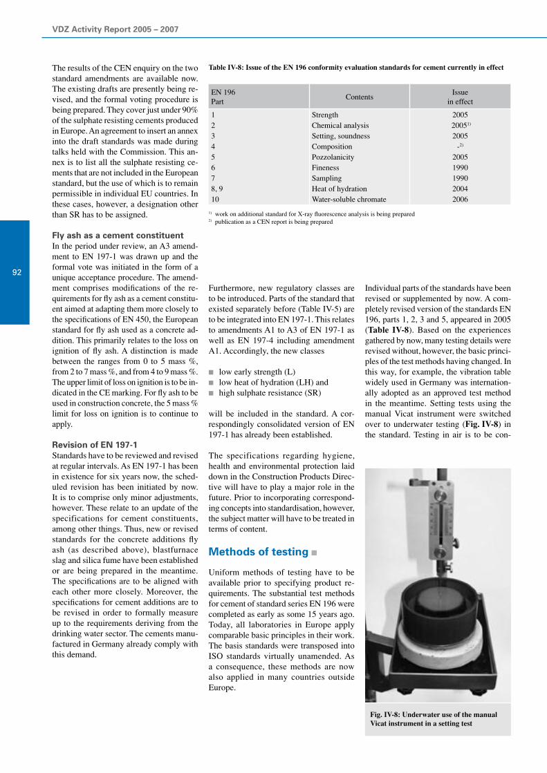
VDZ Activity Report 2005 – 2007
92
The results of the CEN enquiry on the two standard amendments are available now. The existing drafts are presently being re-vised, and the formal voting procedure is being prepared. They cover just under 90% of the sulphate resisting cements produced in Europe. An agreement to insert an annex into the draft standards was made during talks held with the Commission. This an-nex is to list all the sulphate resisting ce-ments that are not included in the European standard, but the use of which is to remain permissible in individual EU countries. In these cases, however, a designation other than SR has to be assigned.
Fly ash as a cement constituentIn the period under review, an A3 amend-ment to EN 197-1 was drawn up and the formal vote was initiated in the form of a unique acceptance procedure. The amend-ment comprises modifications of the re-quirements for fly ash as a cement constitu-ent aimed at adapting them more closely to the specifications of EN 450, the European standard for fly ash used as a concrete ad-dition. This primarily relates to the loss on ignition of fly ash. A distinction is made between the ranges from 0 to 5 mass %, from 2 to 7 mass %, and from 4 to 9 mass %. The upper limit of loss on ignition is to be in-dicated in the CE marking. For fly ash to be used in construction concrete, the 5 mass % limit for loss on ignition is to continue to apply.
Revision of EN 197-1Standards have to be reviewed and revised at regular intervals. As EN 197-1 has been in existence for six years now, the sched-uled revision has been initiated by now. It is to comprise only minor adjustments, however. These relate to an update of the specifications for cement constituents, among other things. Thus, new or revised standards for the concrete additions fly ash (as described above), blastfurnace slag and silica fume have been established or are being prepared in the meantime. The specifications are to be aligned with each other more closely. Moreover, the specifications for cement additions are to be revised in order to formally measure up to the requirements deriving from the drinking water sector. The cements manu-factured in Germany already comply with this demand.
Furthermore, new regulatory classes are to be introduced. Parts of the standard that existed separately before (Table IV-5) are to be integrated into EN 197-1. This relates to amendments A1 to A3 of EN 197-1 as well as EN 197-4 including amendment A1. Accordingly, the new classes
low early strength (L) low heat of hydration (LH) and high sulphate resistance (SR)
will be included in the standard. A cor-respondingly consolidated version of EN 197-1 has already been established.
The specifications regarding hygiene, health and environmental protection laid down in the Construction Products Direc-tive will have to play a major role in the future. Prior to incorporating correspond-ing concepts into standardisation, however, the subject matter will have to be treated in terms of content.
Methods of testing
Uniform methods of testing have to be available prior to specifying product re-quirements. The substantial test methods for cement of standard series EN 196 were completed as early as some 15 years ago. Today, all laboratories in Europe apply comparable basic principles in their work. The basis standards were transposed into ISO standards virtually unamended. As a consequence, these methods are now also applied in many countries outside Europe.
Individual parts of the standards have been revised or supplemented by now. A com-pletely revised version of the standards EN 196, parts 1, 2, 3 and 5, appeared in 2005 (Table IV-8). Based on the experiences gathered by now, many testing details were revised without, however, the basic princi-ples of the test methods having changed. In this way, for example, the vibration table widely used in Germany was internation-ally adopted as an approved test method in the meantime. Setting tests using the manual Vicat instrument were switched over to underwater testing (Fig. IV-8) in the standard. Testing in air is to be con-
EN 196Part
ContentsIssue
in effect
12345678, 910
StrengthChemical analysisSetting, soundnessCompositionPozzolanicityFinenessSamplingHeat of hydrationWater-soluble chromate
2005 20051)
2005-2)
20051990199020042006
1) work on additional standard for X-ray fluorescence analysis is being prepared 2) publication as a CEN report is being prepared
Table IV-8: Issue of the EN 196 conformity evaluation standards for cement currently in effect
Fig. IV-8: Underwater use of the manualVicat instrument in a setting test

IV Quality surveillance and quality assurance of cement
93
tinued only with certain special binders, such as masonry cements. EN 196-3 is to be supplemented accordingly.
The work on a test method for determin-ing the water-soluble chromate content was pushed ahead with under particular pressure in the period under review in or-der to measure up to the provisions of the European chromate directive (see section below). The test method based on mortar extraction was published in 2006.
The factories apply alternative methods for process control purposes in particular. These allow testing to be conducted more quickly and sometimes even automati-cally. For that reason, the question about the extent to which methods other than the reference method can be applied and pos-sibly also standardised is becoming ever more important. The necessary accuracy of the test methods must, however, not be compromised in this process.
The method the factories chiefly apply as an alternative to the traditional chemical reference test methods according to EN 196-2 is X-ray fluorescence analysis. For that reason, an international standard for X-ray fluorescence analysis is being drawn up for the first time (see Chapter III).
Further standardisation activities relate to the initiated revision of EN 196-6 (fine-ness) and EN 196-7 (sampling). There are also intentions to standardise a test method for determining the C
3A content. This pro-
cess is required for standardising sulphate resisting cements.
Test methods (heat of hydration)European cement standardisation offers to equivalent reference methods for deter-mining the heat of hydration of cements. These are the solution method described in EN 196-8 on the one hand, and the semi-adiabatic Langavant method cited in EN 196-9 on the other hand. It is the solution method that has traditionally been applied almost everywhere in Germany – also by the Research Institute as part of quality sur-veillance. A further method that has been applied more and more widely over the past years is isothermal heat flow calorimetry. This method is chiefly employed in facto-ries laboratories for factory quality control. This trend is understandable, as solution ca-lorimetry is both very labour-intensive and requires the handling of hydroflu-oric acid, which is a very toxic hazardous substance. According to the Ordinance on Hazardous Substances, however, hazardous substanc-es have to be banned from the workplace and replaced by less dangerous substances as far as possible (substitution principle). The Research Institute therefore validated isothermal heat flow calorimetry as an alternative method for determining heat of hydration and increasingly employed it in routine tests. An application for the standardisation of heat flow calorimetry in addition to the two existing methods was filed with TC51. The interlaboratory test that VDZ conducted in 2006 can furnish valuable pertinent information. With 21 laboratories performing heat flow calorim- etry and nine laboratories performing solution calorimetry, the participation achieved was high. The results showed a good correlation of the two methods for the five cements investigated. Congruity is best when the hydration time chosen for heat flow calorimetry is about 110 hours. Both repeatability and reproducibility were lower with heat flow calorimetry than with solution calorimetry.
Test methods for special bindersThe European pre-standard for road binders is presently being turned into a standard. The French party in particular suggested that binders used in soil and ground stabili-sation should be included in standardisation on a larger scale than before. Besides the hydraulic constituent, they frequently also contain a substantial portion of unslaked lime. The physical standard test methods according to EN 196-1 and 196-3 cannot be applied without restriction in this case. It was proposed to modify the standard test methods for cement in such a way as to al-low them to be applied to these binders as well. The test method suggested provides for slaking the lime constituent contained in the binder by adding a well-defined quantity of water (Fig. IV-9). The high temperatures generated during the slaking process cause excess water to evaporate. Subsequently, the physical standard test methods are to be applied to the binder slaked in advance accordingly. An inter-laboratory trial in which the Research Institute took part was conducted in early 2007 to test this method. It is still unclear at present whether this method can also be employed with the mixed binders common in Germany, which have lime contents of 50% and more.
In conjunction with the standardisation of super-sulphated cements, the method for strength testing was discussed as well. The consistency of these cements obtained dur-ing the production of standard mortar ac-cording to EN 196-1 is very fluid. An inter- laboratory test was therefore carried out to check whether the test method according to EN 196-1 can be applied or whether it may have to be modified, e.g. by lowering the w/c ratio.
Fig. IV-9: Trials on the pre-slaking of a road binder containing quick lime: appearance of the road binder immediately after mixing (left) and after the slaking process was completed (middle) as well as temperature development during the slaking process (right)
120
100
80
60
40
20
00
1981 1983 1985 1987 1989 1991 1993 1995 1997 1999 2001 2003 2005Jahr
2007
Tem
pera
ture
in
10 20 30 40 50 60 70 80 90 100 110120130Time in min

VDZ Activity Report 2005 – 2007
94
Chromate reduction ofcement
According to European Directive 2003/53/EC, cements and cement containing prepa-rations must not contain more than 2 ppm (0.0002 mass %) water-soluble chromate (relative to the cement content). Most Eu-ropean cements exceed this limit value for raw material reasons. The water-soluble chromate proportion of the cements there-fore has to be diminished to below 2 ppm by adding an appropriate reducing agent. The European Commission recommends applying the test method described in European standard EN 196-10, which was published in October 2006, to determine the water-sol-uble chromate content.
The reduction of water-soluble chromate in cements and cement containing prepa-rations has become a key topic both for cement manufacturers and their clients in recent years. The implementation of the European directive has turned out to be a very complex task. The success of the re-duction measure is crucially determined not only by the process technology execution of chromate reduction, but also by the dif-ferent efficiencies of the various reducing agents per se as well as in relation to the strategy of dosing.
Chromate reduction in GermanyIn Germany, it was initially almost exclu-sively bagged cement that was converted to low-chromate quality by adding chromate reducing agents during the bagging pro-cess. For a couple of years, the German cement industry has offered nearly its en-tire cement range in low-chromate quality. The chromate reduction of bagged cement was primarily accomplished by adding fer-rous sulphate heptahydrate granulates as a reducing agent. Individual manufacturers used powdered tin(II) sulphate instead. When the entire cement output of a ce-ment works is to be reduced, the dosage at the end of production as applied with bagged cements is not the optimum method as the cost and effort involved in mixing and homogenising is considerable. It was therefore tested whether cement clinker and reducing agents can be interground. Ferrous sulphate heptahydrate does not lend itself to this kind of dosing as it gives off its crystal water to the surrounding cement at the high grinding temperatures and is finely ground. Both changes dimin-ish the long-term efficiency of this reducing agent in particular. Reliable reduction of the water-soluble chromate required fer-rous sulphate heptahydrate dosage of up
to 1.0 mass % relative to the cement. The crystal water-free tin(II) sulphate turned out to be more advantageous in this respect. To make economic sense, however, its dosage in cement must not exceed approx. 0.02 to 0.03 mass %. The Research Institute of the Cement Industry therefore began testing other possible chromate reducing agents a few years ago. Attention chiefly focused on the efficiency of ferrous sulphates with a low crystal water content as an alternative to crystal water-free tin(II) sulphate.
Process technology offers various ways of adding chromate reducing agents to cements or cementitious preparations. The associated different stress scenarios influence the effectiveness of the reducing agents. Addition into still warm cement for example constitutes thermal stress, while intergrinding with the cement clinker repre-sents thermal and mechanical stress. Even the influx of atmospheric oxygen, which may occur during the pneumatic transport of the chromate reducing agent or upon its addition to the cement, may have an impact on reducing agent effectiveness. In-depth investigations carried out by the Research Institute of the Cement Industry revealed that even the testing method, particularly the extraction of the water-soluble chro-mate, has considerable influence.
Influence of the test methodThe effectiveness of chromate reducing agents based on ferrous sulphate in ce-ments and cement containing preparations is primarily determined by two factors: the theoretical reduction capacity, i.e. the content of bivalent iron, and the availability of the bivalent iron, i.e. its rate of dissolu-tion upon addition of water to the cement or the cement containing preparation. The rate of dissolution is in turn determined by several factors:
The passive solubility of ferrous sul-phate increases as the crystal water content rises.
The crystal water of the ferrous sulphate heptahydrates and tetrahydrates can al-ready be released at temperatures of less than 60 °C. With the surrounding ce-ment, it forms a layer of cement hydra-tion products on the particle surface of the chromate reducing agent. This layer impedes dissolution (passivation).
The dissolution of the chromate reduc-ing agent can be aided mechanically either by means of a magnetic mixer at the laboratory, or by the aggregates dur-ing mortar and concrete production.
Two ferrous sulphate hydrate compounds were intermixed with a Portland cement (test cement 1) to examine the influence of the chosen test method on the result of chro-mate determination. These ferrous sulphate hydrate compounds were a ferrous sulphate monohydrate (compound 1) and a 1:1 mix of this monohydrate with a ferrous sulphate heptahydrate (compound 2). In accordance with the analysis specification given in the annex to the Technical Rules on Hazardous Substances (TRGS 613), the test cement 1 had a water-soluble chromate content of 17.2 μg Cr(VI)/g cement [= 17.2 ppm Cr(VI)]. At first, 0.3, 0.5 and 0.7 mass % of the respective reducing agents was ad-mixed with this test cement. The content of water-soluble chromate in these mixtures was determined in accordance with the extraction and analysis specifications laid down in the annex to TRGS 613.
When the ferrous sulphate monohydrate compound 1 was dosed to the test cement 1 at quantities ranging from 0.3 (which corresponds to the average dosage of Fe(II) sulphate heptahydrates in German bagged cements) to 1.0 mass %, the success of reduction was only slight (Table IV-9). The water soluble chromate content of test cement 1 did not drop below the limit value of 2 ppm required until the dosage of compound 1 added was 1.5 mass %. A dosage of 2.0 mass % of compound 1 was necessary to safely achieve chromate reduction to considerably less than 1 ppm. By contrast, chromate reducing agent 2 reduced the content of water-soluble chro-mate in test cement 1 to less than 0.2 ppm even when the quantity added was as low as 0.5 mass %. The low reduction effect of the compound 1 monohydrate is attributable to its slower dissolution rate (see above).
Content of reducing
agent in %
Water-soluble chromateportion in ppm
Compound 1 Compound 2
0.0 17.2 17.2
0.3 12.7 0.5
0.5 9.4 0.1
0.7 8.3 0.1
1.0 5.9 0.1
1.5 1.8 < 0.1
2.0 0.1 < 0.1
3.0 < 0.1 < 0.1
Table IV-9: Water-soluble chromate portion of test cement 1 containing different doses of chromate reducing agents compound 1 and compound 2 (extracted and tested in accord-ance with TRGS 613, with oxidation)

IV Quality surveillance and quality assurance of cement
95
The dissolution rate of chromate reducing agents can be increased mechanically. This is chiefly accomplished by generating fresh reactive surfaces by crushing the reducing agent particles. When the water-soluble chromate is extracted according to Euro-pean standard EN 196-10, this comminu-tion is performed by the grating effect of the sand in the standard mortar, which is also the case in practical application. For that reason, the cements containing the compound 1 and compound 2 chromate re-ducing agents were extracted according to this mortar method as well, and the extract was analysed in accordance with TRGS 613. A Portland cement was used as test cement (test cement 2, 11.4 ppm Cr(VI)) in these trials as well. The results of theses tests are described in Table IV-10. Even at a dosage as low as 0.5 mass %, the analysis result was below the detection limit of 0.1 ppm water-soluble chromate also for the cement containing compound 1.
Long-term efficiency of ferrous sulphatesThe reduction effect of chromate reduc-ing agents should not only prevail directly after the production of the low-chromate cements, but last for several months. This is why the durability of the reducing ef-fect of the compound 1 and compound 2 chromate reducing agents was analysed as well. The compound 2 reducing agent was again mixed with test cement 1, and the mixture was extracted and analysed according to TRGS 613. Compound 1 was again admixed to test cement 2 mentioned above and extracted by producing mortar. The extract was analysed in accordance with TRGS 613. Furthermore, all mixtures were stored in closed containers at room temperature for three, six and nine months. Subsequently, their respective content of water-soluble chromate was determined as described above.
Content of reducing
agent in %
Water-soluble chromateportion in ppm
Compound 1 Compound 2
0.0 11.4 11.4
0.3 2.1 0.3
0.5 < 0.1 < 0.1
0.7 < 0.1 < 0.1
Table IV-10: Water-soluble chromate portion of test cement 2 containing different doses of chromate reducing agents compound 1 and compound 2 (extracted in accordance with EN 196-10 and tested in accordance with TRGS 613, with oxidation)
When a 0.5 mass % dose of the compound 1 reducing agent was added, the reduction effect was not even diminished after nine-month storage. The reduction efficiency of the compound 2 reducing agent was very constant throughout the period of nine months investigated. When the dose input was 0.7 mass %, the reducing efficiency of both reducing agents was durably high (Table IV-11).
Ferrous sulphate monohydrates are also adequate chromate reducing agentsThe investigation results available im-pressively show the influence that the mechanically aided dissolution of ferrous sulphate hydrates has on their effectiveness as chromate reducing agents. Although hydrate crusts diminish the passive solu-bility of these chromate reducing agents, they simultaneously preserve the bivalent iron. The hydrate crusts are generated by the reaction of the crystal water in the fer-rous sulphate hydrates with the surround-ing cement. Ferrous sulphate monohydrate represents an exception as its crystal water molecule is very strongly combined. In the practical application of cement in mortar and concrete, the dissolution of these re-ducing agents and thus their effectiveness is aided mechanically by the grating effect caused by the aggregates. This is taken into
Water-soluble chromate portion in ppm
Compound 1 Compound 2
Test cement without reducing agent
without storage 11.4 17.2
after 3-month storage 11.2 17.0
after 6-month storage 11.1 16.8
after 9-month storage 11.4 16.7
Test cement containing 0.5% reducing agent
without storage < 0.1 0.1
after 3-month storage < 0.1 0.2
after 6-month storage < 0.1 0.2
after 9-month storage < 0.1 0.1
Test cement containing 0.7% reducing agent
without storage < 0.1 0.1
after 3-month storage < 0.1 < 0.1
after 6-month storage < 0.1 0.1
after 9-month storage < 0.1 < 0.1
Table IV-11: Water-soluble chromate portion of test cement 1 containing different doses of chromate reducing agent compound 2 (extracted and tested in accordance with TRGS 613, with oxidation) and of test cement 2 containing different doses of chromate reducing agent compound 1 (extracted in accordance with EN 196-10 and tested in accordance with TRGS 613, with oxida-tion) after varying storage durations
account in the new European test method for determining the water-soluble chromate in cements in accordance with EN 196-10 in that it provides for the extraction of wa-ter-soluble chromate by producing standard mortar. The importance inherent in the practical orientation of this test method be-comes particularly evident from evaluating the efficiency of ferrous sulphate monohy-drates as chromate reducing agents. When previous national European test methods, such as TRGS 612 or Danish standard DS 1020, were applied, their lower passive solubility created the impression that their efficiency was low. Testing according to the method described in EN 196-10, however, demonstrates their high efficiency. Given their lower crystal water content, they are further less sensitive to passivation, which is conducive to their long-term efficiency.
Influence of thermal, chemical and mechanical stress on the efficiency of chromate reducing agentsDifferent dosing strategies for adding chro-mate reducing agents to cement have estab-lished themselves in the cement industry. Reducing agent addition already in the finish mill is particularly interesting. This kind of dosage constitutes the best way of ensuring that the reducing agent is input into the ce-ment homogeneously and in a way that is safe under process technology aspects.

VDZ Activity Report 2005 – 2007
96
However, all dosing methods constitute stress for the chemically sensitive reducing agents. During the pneumatic transport of the reducing agent, oxidation caused by oxy- gen may occur. The frequently high tem-perature of the cement clinker even before and during grinding represents a consider-able thermal stress that may accelerate the chemical conversion of the reducing agent and thus diminish its efficiency. Besides, the chromate reducing agent is comminuted by intergrinding with the cement clinker. As a result, it becomes less probable that the dissolution of the reducing agent will be aided mechanically by the aggregates during practical application.
The possible stresses that chromate re-ducing agents may be exposed to during their addition to cement were simulated in laboratory trials. To that end, the chromate reducing agents were admixed to a test ce-ment in a heatable laboratory ball mill at different temperatures (room temperature, 80 °C, 120 °C). The mixing process was performed both with oxygen being present (laboratory air) and excluded (argon gas) in order to test the sensitivity to oxidation of the reducing agents. The same tests were also conducted after the laboratory mill had been filled with mill feed in order to inves-tigate the influence of the mechanical stress applied during the intergrinding of cement and chromate reducing agents.
Two ferrous sulphate heptahydrates (hepta-hydrate A, heptahydrate B), two ferrous sulphate monohydrates (monohydrate A, monohydrate B) and two tin(II) sulphates (tin sulphate A, tin sulphate B) were em-ployed in the investigations.
The efficiency of heptahydrate A and hepta-hydrate B in the test cements obtained by mixing was very good immediately after production (Fig. IV-10). Higher tempera-tures and atmospheric oxygen diminished the efficiency of these chromate reducing agents after three-month storage (Fig. IV-11). Intergrinding with cement at low temperatures diminishes the long-term efficiency of the heptahydrates. The me-chanically aided dissolution of the reduc-ing agent particles already comminuted by grinding and passivated by the formation of hydrate crusts during storage is possible to a limited extent only (Fig. IV-13).
Fig. IV-10: Water-soluble chromate portion of a test cement after admixing various chromate reducing agents (figures in brackets: dosage in mass %) at different cement temperatures and atmospheres in the mixer (testing immediately after mix production; extracted and tested in accordance with EN 196-10)
Chro
miu
m(V
I) in
ppm
16
14
12
10
8
6
4
2
0Heptahydrate A
(0.3)Heptahydrate B
(0.3)Monohydrate B
(0.5)Monohydrate A
(0.5)Tin sulphate A
(0.025)Tin sulphate B
(0.025)
20 C air
20 C argon
80 C air
80 C argon
120 C air
120 C argon
Fig. IV-11: Water-soluble chromate portion of a test cement after admixing various chromate reducing agents (figures in brackets: dosage in mass %) at different cement temperatures and atmospheres in the mixer (testing after three-month storage of the mixes; extracted and tested in accordance with EN 196-10)
Chro
miu
m(V
I) in
ppm
16
14
12
10
8
6
4
2
0Heptahydrate A
(0.3)Heptahydrate B
(0.3)Monohydrate B
(0.5)Monohydrate A
(0.5)Tin sulphate A
(0.025)Tin sulphate B
(0.025)
20 C air
20 C argon
80 C air
80 C argon
120 C air
120 C argon
Fig. IV-12: Water-soluble chromate portion of a test cement after intergrinding with various chromate reducing agents (figures in brackets: dosage in mass %) at different cement tem-peratures and atmospheres in the mill (testing immediately after mix production; extracted and tested in accordance with EN 196-10)
Chro
miu
m(V
I) in
ppm
16
14
12
10
8
6
4
2
0Heptahydrate A
(0.3)Heptahydrate B
(0.3)Monohydrate B
(0.5)Monohydrate A
(0.5)Tin sulphate A
(0.025)Tin sulphate B
(0.025)
20 C air
20 C argon
80 C air
80 C argon
120 C air
120 C argon

IV Quality surveillance and quality assurance of cement
97
When monohydrate A and monohydrate B where admixed to the cement, their efficiency was different. Monohydrate A was insensitive to higher temperatures and atmospheric oxygen immediately after the mixtures had been produced. By contrast, monohydrate B suffered an increasing loss of efficiency as a result of higher temperatures during the mixing process (Fig. IV-10). After three-months storage, the content of water-soluble chromate in some of the mixtures was measurable as well (Fig. IV-11). However, intergrinding resulted in amazingly high efficiency of the two monohydrates regardless of the other dosing conditions (Figs. IV-12 and IV-13).
When tin(II) sulphates A and B were added to the cement by admixing, their efficiency was different, but good in general. Imme-diately after the mixtures had been pro-duced at low temperatures, the coarser tin sulphate A was slightly less effective than the pulverulent tin sulphate B (Fig. IV-10). Following intergrinding with the cement under varying conditions, however, both tin(II) sulphates always worked very reli-ably (Figs. IV-12 and IV-13).
Consequences for practical applicationTo ensure high and, in particular, more durable high efficiency of the ferrous sulphate heptahydrates, they should not be comminuted, which is the case when they are interground with the cement, for example. The efficiency of the hepta-hydrates strongly depends on the degree to which their dissolution is aided mechani-cally by grinding and grating effects during the practical application of the cements reduced by their addition. These mechani-cal influences remove from the reducing agent particles the passivating hydrate
Fig. IV-13: Water-soluble chromate portion of a test cement after intergrinding with vari-ous chromate reducing agents (figures in brackets: dosage in mass %) at different cement temperatures and atmospheres in the mill (testing after three-month storage of the mixes; extracted and tested in accordance with EN 196-10)
crusts generated by the reaction of the sur-rounding cement and the crystal water of the reducing agent. These crusts impede the dissolution of the particles. For that reason, chromate reducing agents based on ferrous sulphate heptahydrates should preferably be added to the cement by mix-ing, as this method ensures that they are still adequately coarse to permit their dis-solution to be aided mechanically.
Ferrous sulphate monohydrates and tin(II) sulphates exhibited little sensitivity to high temperatures and atmospheric oxygen. Comminution by grinding enhances their reduction effect. As a result of these proper-ties, these reducing agents are preferable for addition to the cement by intergrinding.
The results of the study on the efficiency of different chromate reducing agents that were presented indicate their respective op-timum ways of dosing. The characteristic
particularities of the individual reducing agents have to be taken into account in the process technology implementation of chromate reduction and as early as in dos-ing facility design. It is not just the chemi-cal, but also the physical properties of the reducing agents, such as their tendency to agglomerate under certain conditions, that have to be taken into consideration. The manufacturing process for reducing agents has to be designed in such a way as to ensure that their reduction potential is preserved to the highest extent possible and their quality is reproducible. The actual efficiency of the chromate reducing agents is, however, only reflected correctly by a test method that realistically reproduces the dissolution of the reducing agent particles under practical conditions. Since October 2006, harmonised European standard EN 196-10 has provided such a test method for verifying the successful implementation of the European Directive 2003/53/EC.
Chro
miu
m(V
I) in
ppm
16
14
12
10
8
6
4
2
0Heptahydrate A
(0.3)Heptahydrate B
(0.3)Monohydrate B
(0.5)Monohydrate A
(0.5)Tin sulphate A
(0.025)Tin sulphate B
(0.025)
20 C air
20 C argon
80 C air
80 C argon
120 C air
120 C argon

VDZ Activity Report 2005 – 2007
98Concrete constituents, concrete technology and concrete engineering
V
Construction of the Cologne north-south urban railway. Tunnel tube with tubbing
Research and services in the “concrete technology” domain cover topical and important issues in the fields of concrete constituen-ts, concrete technology and concrete application. The erection of durable structures using cements with several main constituents again formed an essential part of the research activities. The main focus was placed on the durability of concrete made from ce-ments containing blastfurnace slag, limestone and fly ash – either separately or in combination - as main constituents in addition to Portland cement clinker. In this context, the limitations of possible cement compositions within and outside the scope of cement standard EN 197 were probed.
Several research projects again dealt with preventing a deleterious alkali-silica reaction (ASR) in concrete. The advance of aggre-gate test methods and the development of a performance test method for assessing the ASR risk potential of concrete compositions constituted key subjects in this context.
The interaction of cement and admixtures was another research focus of the concrete technology department. This included the examination of super-plasticizers of the new generation, shrinkage-reducing admixtures and air entraining agents. Other activities comprised the modelling of cement hydration, ultra high-performance concrete (UHPC) and issues of sustainability in construction with concrete.
Demand for concrete technology consultancy and expert advisory services provided by the Research Institute has increased consi-derably in recent years. One of the key activities presently consists of developing optimised concrete and mortar mixtures tailored to the client’s respective area of application. The execution of structure analyses and the evaluation of a structure’s condition form part of the portfolio, as does the elaboration of reinstatement concepts. Finally, our experts deal with questions regarding alkali- silica reaction and chemical attacks on concrete.
The results of scientific work were published in lectures and reports, and immediately found their way into standardisation work. Based on the investigations of the Research Institute, for example, the 60 °C concrete test was included in an informative annex to the newly published alkali guidelines to gain further experiences. The 60 °C concrete test allows assessment of the sensitivity to alkalis of aggregates as early as after three months. VDZ will continue taking an active part in the extrapolation of the alkali guidelines in the coming years. Attention will focus on specifying the conditions underlying the execution of performance tests. These performance tests serve to assess the sensitivity to alkalis of a specified concrete composition.

V Concrete constituents, concrete technology and concrete engineering
99

VDZ Activity Report 2005 – 2007
100
Fig. V-1: Schematic rep-resentation of the properties of cements and concretes made using two ce-ment types with several main constituents (blue lines) in comparison with Portland cement (black line) taken as reference ce-ment
Durability
Standardstrength
Earlystrength
Workability
Costs
Environment
120100806040200
140
Cements with several main constituents
The production processes and the applica-tion properties of modern cements have to meet a large variety of requirements today. In addition to the strength formation poten-tial and adequate workability, the perfor-mance profile customers expect especially includes the durability of the concrete made from the cement. For cement manufac-turers, costs also play a role. Moreover, paramount environmental policy targets increasingly have an impact on the entire construction sector.
Technical and ecological optimisationCement manufacture is a demanding opti-misation task in which all requirements have to be given adequate consideration. The manufacture of cements with several main constituents is of particular importance in this context. Given the use of other main constituents, the clinker content of these cements is reduced. They therefore offer the possibility of limiting CO
2 emissions
relative to one tonne of cement in cement manufacture.
No cement – not even Portland cement – of-fers the optimum solution for all possible applications. This is illustrated schemati-cally in Fig. V-1 for two cement types with several main constituents, which are com-pared with Portland cement (black line) that is taken as a reference variable. As this consist of several main constituents, CEM II and CEM III cements offer the possibility of combining the individual advantages of the individual components. In addition to aspects of CO
2 reduction and conservation
of resources, cements containing several main constituents are excellently suited for optimising properties relevant for application, such as workability, strength development or durability. For that reason, CEM II and CEM III cements are now the standard cements for ready-mixed concrete applied in building construction and civil engineering in many regions.
Research activities at the Research Institute focus on the durability of concrete made from cements containing blastfurnace slag, limestone and fly ash – either separately or in combination – as main constituents in addition to Portland cement clinker. In this context, the limitations of possible cement compositions within and outside the scope of cement standard EN 197 are probed. In-vestigations cover the influence of different cements on porosity and pore size distri-bution, carbonation, resistance to chloride
penetration and resistance to freeze-thaw and freeze-thaw with de-icing salt.
The properties of cements containing up to 35 mass % limestone – used separately or in combination with blastfurnace slag – and their effects on concrete durability were dealt with in the Activity Report 2003-2005. The research results described below cover Portland-fly ash cements containing up to 35 mass % siliceous fly ash (hard coal fly ash V) and Portland-composite cements containing fly ash (V) and blast-furnace slag (S).
Durability of concrete made from Portland-composite cements containing fly ashBased on the results of a research project conducted at the technical universities of Aachen and Munich, use of the k-value concept for hard coal fly ash as a concrete addition in concrete exposed to freeze-thaw with de-icing salt (exposure classes XF2 and XF4) became permissible by virtue of Amendment A2 to DIN 1045-2 in early 2007. As a consequence, the use of cements containing fly ash is no longer excluded for these applications either (cf. section on standardisation). If fly ash is used as a main constituent in Portland-composite cements, the content of fly ash can be higher than if it is used as a concrete addition since the application of optimised cements allows the adjustment of a level of concrete perfor-mance that meets practical demands.
The Research Institute carried out ex-tensive investigations on concretes made from cements containing fly ash as part of AiF-sponsored research. The investigations
revealed that the restrictions of use for ce-ments containing fly ash were lifted with justification. They also dealt with fly ash as a concrete addition being offset against the water/cement ratio and the minimum cement content when cements containing fly ash are utilised. Given the restrictions imposed on the use of cements contain-ing fly ash until the publication of the A2 Amendment to DIN 1045-2, attention was primarily directed to the resistance of concrete to freeze-thaw and freeze-thaw with de-icing salt. Supplementary investi-gations, however, also dealt with the car-bonation behaviour and the resistance to chloride penetration of the concretes.
The test cements were made up of the main constituents clinker (K), blastfurnace slag (S) and hard coal fly ash (V1, V2, V3) as well as an optimised sulphate agent mix. The fly ashes came from two different pow-er stations, with fly ashes V1 and V3 having the same origin. The fly ashes especially differed in terms of fineness and loss on ignition, but their contents of Al
2O
3, Fe
2O
3,
CaO and SiO2 varied as well.
Fly ashes V1, V2 and V3 were used as main cement constituents, and fly ash V2 was additionally utilised as a concrete addition. It was offset against the equivalent water/cement ratio at a k-value of 0.4.
The laboratory-made cements containing fly ash were optimised in terms of granu-lometry. The clinker and the blastfurnace slag were ground in semi-industrial labora-tory ball mills and subsequently mixed with the fly ash (largely in the original state) and a sulphate agent geared to the intended

V Concrete constituents, concrete technology and concrete engineering
101
Fig. V-2: Carbo-nation depths of concretes made from Portland-fly ash cements and reference cements as well as fly ash as an addition as a function of testing age and cement compo-sition
Fig. V-3: Chlo-ride migration coefficients of concretes containing Portland-fly ash cements and re-ference cements as well as fly ash as an additi-on as a function of testing age and cement composition
8
7
6
5
4
3
2
1
00 100 200 300 400
Age in days
Carb
onat
ion
dept
h in
mm
CEM ICEM III/ACEM II with 35% V2CEM II with 25% V2CEM II with 20% V2
c = 240 kg/m3
f = 79.2 kg/m3
(w/c)eq = 0.65
20
15
10
5
0CEM I CEM II CEM II CEM II CEM III/A
(20% V2) (25% V2) (35% V2)
D CI, M
in 10
-12 m
2 /sc = 270 kg/m3
f = 89.1 kg/m3
(w/c)eq = 0.50
35 d98 d
cement mix. The contents of fly ash ranged between 20 and 35 mass % for the Portland- fly ash cements, and the Portland-com- posite cements were made up of 15 or 25 mass % fly ash and 10, 15 or 20 mass % blastfurnace slag, respectively. The fineness of hard coal fly ash V2 chiefly used in these cements was approx. 3 700 cm2/g Blaine. In case of a high fly ash content of 35 mass % or utilisation of the fairly coarse fly ash V3 (3 350 cm2/g), a more narrow particle size distribution of the clinker was chosen to attain cement strength meeting practical demands.
Investigations comparing concrete durabil-ity presuppose that the concretes examin-ed possess a comparable strength level, which serves as a parameter for similar microstructure formation. The cements investigated therefore should have com-parable 28-d compressive strength, which ranges between approx. 44 and 48 MPa in the domain of practical relevance for German cements of strength class 32.5 R. The reference cements used were a factory-made CEM I and a laboratory-made CEM III/A of strength class 32.5 R.
CarbonationCarbonation is essential for the durability of reinforced concrete. The rate of carbona-tion is determined by the diffusion of CO
2
through the concrete void system.
By way of example, Fig. V-2 shows the development with time of the carbonation depths of several concretes investigated. The concretes were made from the two reference cements or the Portland-fly ash cements, respectively. Cements containing fly ash were utilised in combination with fly ash used as an addition. The concretes were characterised by a cement content of c = 240 kg/m3, an equivalent water/ce-ment ratio of (w/c)
eq = 0.65 and a fly ash
content of f = 79.2 kg/m3 (f/c = 0.33). The carbonation depths of the concretes made from cements containing fly ash were lower than those of the CEM III/A concrete. Even when combined with fly ash as a concrete addition, CEM III/A can be employed in all areas of application (exposure classes). The carbonation depths of these concretes further ranged within the bandwidth of values that can be assumed for the cement types CEM I to CEM III/B under the given test conditions according to publications.
The results confirmed that, even in combi-nation with hard coal fly ash as a concrete addition, these Portland-fly ash cements can be used in all exposure classes applicable for carbonation-induced reinforcement cor-
rosion. For the case of cements containing fly ash being applied in combination with fly ash as a concrete addition, the standard provides for additional safety by limiting the fly ash content that may be offset to f/c = 0.25 instead of the maximum value of f/c = 0.33 that is normally applicable.
Resistance to chloride penetrationThe resistance of the concrete to chloride penetration was determined by means of a quick test method (migration test). The specimens were stored in water up to the testing age of 35 days or 98 days, respec-tively.
Concretes conforming to exposure class XD2/XS2 were made with a water/cement ratio of w/c = 0.50 and a cement content of c = 320 kg/m2 (without addition). The chlo-ride migration coefficients D
Cl,M measured
when Portland-fly ash cements containing
up to 35 mass % siliceous fly ash were used ranged between approx. 10 and 20 · 10-12 m2/s at an age of 35 days. At a testing age of 98 days, the specimens exhibited a markedly lower chloride migration coeffi-cient D
Cl,M ranging in an order of magnitude
of 5 to 6 · 10-12 m2/s. The measurement values determined fall within the range of values that publications cite for Portland cements.
When Portland fly ash cements containing 20, 25 and 35 mass % fly ash as a main ce-ment constituent were used in combination with fly ash as a concrete addition, the con-cretes had a chloride migration coefficient D
Cl,M ranging between approx. 10 and 12 ·
10-12 m2/s (Fig. V-3) after 35 days. After 98 days, the values were at the level of the CEM III/A concrete containing fly ash (D
Cl,M approx. 3 · 10-12 m2/s).

VDZ Activity Report 2005 – 2007
102
Fig. V-4: Scaling of concretes made from Portland-fly ash cements and reference cement CEM III/A as well as fly ash as an addition as a function of the number of freeze-thaw cycles and cement compo-sition (CF method); acceptance criterion: scaling < 1.0 kg/m2 after 28 freeze-thaw cycles; light blue marking: range of values of CEM I concretes, data of the Research Institute
Fig. V-5: Relative dynamic modulus of elasticity of concretes made from Portland-fly ash cements and reference cement CEM III/A as well as fly ash as an addition as a function of the number of free-ze-thaw cycles and cement composition (CIF method); acceptance criterion: relative dynamic modulus of elasticity > 75% after 28 freeze-thaw cycles; light blue marking: range of values of CEM I concretes, data of the Research Institute
2.00
1.75
1.50
1.25
1.00
0.75
0.50
0.25
0.00
0 7 14 21 28 35 42 49 56 63Freeze-thaw cycles
CEM III/ACEM II with 20% V2CEM II with 25% V2CEM II with 35% V2
c = 270 kg/m3
f = 89.1 kg/m3
(w/c)eq = 0.50
BAW criterion
Scali
ng in
kg/m
2
120
100
80
60
40
20
00 7 14 21 28 35 42 49 56 63
Freeze-thaw cycles
CEM III/ACEM II with 20% V2CEM II with 25% V2CEM II with 35% V2
c = 270 kg/m3
f = 89.1 kg/m3
(w/c)eq = 0.50
Relat
ive d
ynam
ic m
odul
us o
f elas
ticity
in %
BAW criterion
The results confirmed that Portland-fly ash cements in combination with hard coal fly ash as a concrete addition can be utilised in all exposure classes applicable for chlo-ride-induced reinforcement corrosion as well. The concrete standard limits the fly ash content that can be offset when fly ash is simultaneously used as a main cement constituent and as a concrete addition to f/c = 0.25 in this case as well.
Resistance to freeze-thaw and freeze-thaw with de-icing saltWhen damage is caused by freeze-thaw at-tack, a distinction is made between external and internal damage. External damage is visible as surface scaling. Internal damage to the microstructure can, for example, be ascertained by means of ultrasonic tran-sit time measurement and the dynamic modulus of elasticity thus derived. The results of testing freeze-thaw resistance according to the CF/CIF method and the results of testing resistance to freeze-thaw with de-icing salt according to the CDF method are presented and evaluated below. In Germany, limit values for scaling (CF/CDF method) and limit values for internal damage to the microstructure (CIF method) were laid down in the “Freeze-thaw testing of concrete” guidelines issued by the Feder-al Waterways Engineering and Research Institute (BAW).
The concretes in which cements con-taining fly ash portions between 20 and 35 mass % had been used in combination with fly ash as a concrete addition (ce-ment content c = 270 kg/m3, equivalent
water/cement ratio (w/c)eq
= 0.50, fly ash content f = 89.1 kg/m3) did not display significantly more marked scaling than the concretes made from the reference ce-ments CEM I and CEM III/A in the tests conducted. Fig. V-4 illustrates that the scaling of all concretes determined on the basis of the CF method was substantially below the acceptance criterion of 1.0 kg/m² after 28 freeze-thaw cycles specified in the “Freeze-thaw testing of concrete” guidelines issued by he Federal Waterways Engineering and Research Institute (BAW). As shown in Fig. V-5, these concretes had a relative dynamic modulus of elasticity of more than 75% (BAW acceptance criterion for the CIF method) after 28 freeze-thaw cycles.
The CDF test serves to determine resistance to straining by freeze-thaw in combination with exposure to de-icing agents. When the resistance to freeze-thaw with de-icing salt of concretes with artificially entrained air voids is tested, surface scaling is predomi-nant and takes precedence in evaluation. Resistance to freeze-thaw with de-icing salt was tested for concretes without additions having a cement content of c = 320 kg/m3 and a water/cement ratio of w/c = 0.50. The results are shown in Fig. V-6. The scaling of the concretes made from the Portland- cement and from the cements containing fly ash ranged between 300 and 900 g/m2 after 28 freeze-thaw cycles. They were thus considerably below the acceptance criterion of 1 500 g/m2 after 28 freeze-thaw cycles applicable for this method.
Blastfurnace slag as a further main constituent in Portland-composite cements containing fly ashThe research project described also com-prised the investigation of concretes made from Portland-composite cements contain-ing blastfurnace slag as a further main constituent in addition to clinker and hard coal fly ash. By way of example, Fig. V-7 shows the relative dynamic moduli of elasticity determined by means of the CIF method (freeze-thaw attack without de-icing salt) for the concretes having a wa-ter/cement ratio w/c = 0.50 and a cement content c = 320 kg/m3 (without addition). No differentiation between the concretes made from the various cements containing fly ash and blastfurnace slag was discern-ible. The concretes investigated complied with the acceptance criterion of 75% after 28 freeze-thaw cycles specified in the BAW “Freeze-thaw testing of concrete” guidelines by a wide margin. The relative dynamic elasticity moduli of the concretes made from Portland-composite cements ranged within the bandwidth of the values obtained for concretes made from Portland cements. At a maximum of 0.17 kg/m2 after 56 freeze-thaw cycles, the scaling of the concretes was considerably below the BAW acceptance criterion of 1.0 kg/m2 after 28 freeze-thaw cycles.
Impact of fly ash quality and fineness Cements containing 30 mass % fly ash of different quality (loss on ignition) and different fineness, respectively, were made in several tentative experiments. The con-cretes without additions made from these
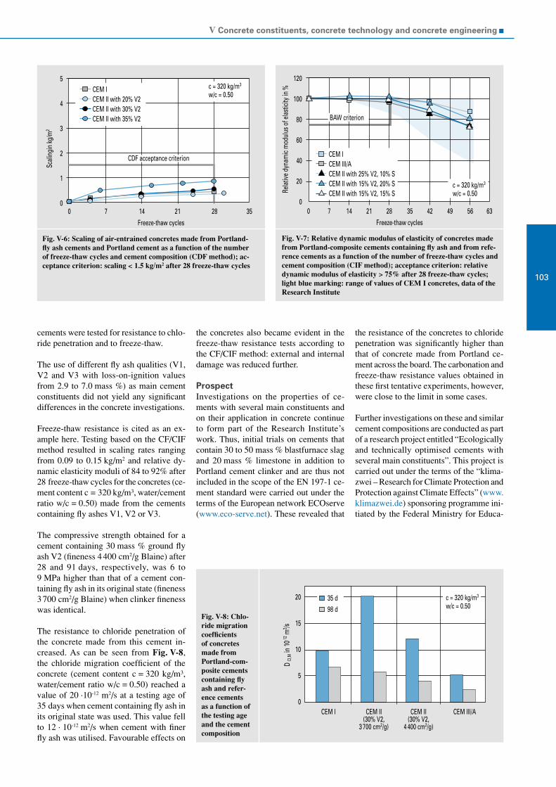
V Concrete constituents, concrete technology and concrete engineering
103
Fig. V-6: Scaling of air-entrained concretes made from Portland-fly ash cements and Portland cement as a function of the number of freeze-thaw cycles and cement composition (CDF method); ac-ceptance criterion: scaling < 1.5 kg/m2 after 28 freeze-thaw cycles
Fig. V-7: Relative dynamic modulus of elasticity of concretes made from Portland-composite cements containing fly ash and from refe-rence cements as a function of the number of freeze-thaw cycles and cement composition (CIF method); acceptance criterion: relative dynamic modulus of elasticity > 75% after 28 freeze-thaw cycles; light blue marking: range of values of CEM I concretes, data of the Research Institute
Fig. V-8: Chlo-ride migration coefficients of concretes made from Portland-com-posite cements containing fly ash and refer-ence cements as a function of the testing age and the cement composition
CEM ICEM II with 20% V2CEM II with 30% V2CEM II with 35% V2
c = 320 kg/m3
w/c = 0.50
CDF acceptance criterion
0 7 14 21 28 35
Scali
ngin
kg/m
2
5
4
3
2
1
0
Freeze-thaw cycles
CEM ICEM III/ACEM II with 25% V2, 10% SCEM II with 15% V2, 20% SCEM II with 15% V2, 15% S
120
100
80
60
40
20
00 7 14 21 28 35 42 49 56 63
Freeze-thaw cycles
Relat
ive d
ynam
ic m
odul
us o
f elas
ticity
in %
c = 320 kg/m3
w/c = 0.50
BAW criterion
CEM I CEM II(30% V2,
3 700 cm2/g)
CEM II(30% V2,
4 400 cm2/g)
CEM III/A
20
15
10
5
0
D CI
,M in
10-1
2 m2 /s
c = 320 kg/m3
w/c = 0.5035 d98 d
cements were tested for resistance to chlo-ride penetration and to freeze-thaw.
The use of different fly ash qualities (V1, V2 and V3 with loss-on-ignition values from 2.9 to 7.0 mass %) as main cement constituents did not yield any significant differences in the concrete investigations.
Freeze-thaw resistance is cited as an ex-ample here. Testing based on the CF/CIF method resulted in scaling rates ranging from 0.09 to 0.15 kg/m2 and relative dy-namic elasticity moduli of 84 to 92% after 28 freeze-thaw cycles for the concretes (ce-ment content c = 320 kg/m³, water/cement ratio w/c = 0.50) made from the cements containing fly ashes V1, V2 or V3.
The compressive strength obtained for a cement containing 30 mass % ground fly ash V2 (fineness 4 400 cm2/g Blaine) after 28 and 91 days, respectively, was 6 to 9 MPa higher than that of a cement con-taining fly ash in its original state (fineness 3 700 cm2/g Blaine) when clinker fineness was identical.
The resistance to chloride penetration of the concrete made from this cement in-creased. As can be seen from Fig. V-8, the chloride migration coefficient of the concrete (cement content c = 320 kg/m³, water/cement ratio w/c = 0.50) reached a value of 20 ·10-12 m2/s at a testing age of 35 days when cement containing fly ash in its original state was used. This value fell to 12 · 10-12 m2/s when cement with finer fly ash was utilised. Favourable effects on
the concretes also became evident in the freeze-thaw resistance tests according to the CF/CIF method: external and internal damage was reduced further.
ProspectInvestigations on the properties of ce-ments with several main constituents and on their application in concrete continue to form part of the Research Institute’s work. Thus, initial trials on cements that contain 30 to 50 mass % blastfurnace slag and 20 mass % limestone in addition to Portland cement clinker and are thus not included in the scope of the EN 197-1 ce-ment standard were carried out under the terms of the European network ECOserve (www.eco-serve.net). These revealed that
the resistance of the concretes to chloride penetration was significantly higher than that of concrete made from Portland ce-ment across the board. The carbonation and freeze-thaw resistance values obtained in these first tentative experiments, however, were close to the limit in some cases.
Further investigations on these and similar cement compositions are conducted as part of a research project entitled “Ecologically and technically optimised cements with several main constituents”. This project is carried out under the terms of the “klima-zwei – Research for Climate Protection and Protection against Climate Effects” (www.klimazwei.de) sponsoring programme ini-tiated by the Federal Ministry for Educa-

VDZ Activity Report 2005 – 2007
104
tion and Research (BMBF). In addition to laboratory investigations of cements made at the Research Institute’s grinding and mixing plants, the project is scheduled to include the industrial-scale manufacture of new cements. Furthermore, the con- cretes made from these cements are to be monitored under practical conditions. The contents of the project are attended by an attendant committee. In addition to the pro- ject partners VDZ, Spenner Zement GmbH & Co. KG, HeidelbergCement AG, Federal Waterways Engineering and Research In- stitute and the engineering firm Prof. Schießl, the parties represented on the committee also include the ready-mixed concrete in-dustry, the manufacturers of blastfurnace slag, the fly-ash industry, the construction industry and the German Committee for Structural Concrete. An accompanying process performing communication func-tions in particular was developed for the “Research for Climate Protection and Pro-tection against Climate Effects” sponsoring programme. The accompanying process is implemented by the Economy/Ecology Re-search Unit of the Institute of the German Economy (IW) in Cologne.
Cement and admixtures
The use of concrete admixtures to control the properties of the fresh and hardened concrete is state of the art in concrete pro-duction today. Some 90% of the concrete produced in Germany contains concrete admixtures. Overall, more than 550 con-crete admixtures which can be classified in 14 different functional groups are presently available in Germany. At approx. 75%, concrete plasticisers and super-plasticisers account for the lion’s share.
There is still a substantial lack of scientifi-cally founded understanding of the precise working mechanisms of some concrete admixtures. The influence that concrete ad-mixtures have on the hydration of cement and thus on the properties of fresh and/or hardened concrete is most often deter-mined empirically and forms the subject of controversial discussions. This applies to super-plasticisers on the basis of poly-carboxylate ether, shrinkage reducing ad-mixtures and novel air-entraining concrete admixtures in particular, which formed the subject of extensive investigations at the Research Institute.
Super-plasticisersThe use of highly efficient super-plasti-cisers is indispensable for achieving op-timum workability of high-performance concrete, such as high-strength or self-compacting concrete.
Synthetic organic polymers with carbox-ylic groups, such as polycarboxylate ethers (PCE), constitute an advance in the field of active ingredients contained in super-plas-ticisers. Some 45% of the super-plasticisers utilised today are based on PCE, and the tendency is rising. PCEs consist of main chain molecules, such as polyacrylic acid, and side chain molecules, such as poly-ethylene oxide, which are fixed to the main chain. Via their negatively charged main chain, the PCEs adsorb on the positively charged surfaces of the cement, its hydra-tion products and other fine solids particles. The dispersing effect is largely attributable to the steric repulsion of the side chains. Variation of the charge and the length ratio of the main chain and the side chains allows adjustment of different properties, such as strong initial plasticising effect and/or extended workability of fresh concrete. These can each entail differences in the retardation of cement setting. The precise mechanisms of super-plasticiser molecules being adsorbed on the cement particles and other fine solids particles are still unknown, however. Moreover, the influence that the chemical structure of the super-plasticiser molecules, the chemical composition of the cements and ambient conditions have on dispersion has not been fully explained either. Practical application shows that PCEs can be more sensitive to temperature variations or variations in cement compo-sition than the classic super-plasticisers. This may for example result in a faster decrease of consistency, segregation, in-tensive bleeding or significant retardation of strength development. More profound understanding of the interaction of super-plasticisers and cement is required to pre-vent such undesired reactions.
For that reason, the influence that the chemi- cal structure of the PCE molecules and the chemico-mineralogical composition of cements have on the dispersion and the strength development of pastes and mor-tars was investigated as part of a research project sponsored by the AiF. The essential parameters of admixtures and cement that may cause undesired reactions, such as ra-pid loss of workability or low early strength, were investigated systematically.
Cements and PCE super-plasticisersA database for the chemical composi-tion and molecular structure of super- plasticisers based on PCE as well as the chemico-mineralogical and physical composition of customary cements was compiled. Overall three batches of 15 commercial PCE-based super-plasticisers and ten commercial cements from different manufacturers were analysed. Moreover, the composition of the pore solution of ce-ment pastes made from these cements and super-plasticisers was determined over a hydration period of up to 120 minutes.
The analysis of the super-plasticisers re-vealed that some of the 15 super-plasticisers contained nearly identical PCE molecules. A total of eight different PCE types were identified, which are listed in Table V-1. The main chain lengths, which were de-termined by GPC and NMR analysis, ranged between 27 and 144 methacrylic acid (MAA) units. The side chains were made up of 19 to 116 ethylene oxide (EO) units each. The charge units relative to the main chain ranged between 0.5 and 23 charge equivalents. Fig. V-9 summa-rises of the molar weight M
w determined
for each of the three batches of 15 super- plasticisers. In general, the individual batches of the super-plasticisers tallied well. Industrially made polymerizates can usually not be expected to be more homogeneous. Deviations, which for ex-ample occurred between the first charge of FM01 in comparison to the second and third charge, were almost exclusively attrib- utable to high-molecular mass portions in the polymer which, however, were largely insignificant in terms of concentration. These did not have any substantial impact on super-plasticiser effectiveness.
Three minutes after water addition, the sulphate content of the pore solution of the cement paste ranged between approx. 3.5 and 15.5 g/l. This variation bandwidth is chiefly attributable to the different com-position and solubility of the sulphate agents and to the differnet alkali sulphate contents of the ten cements investigated. Even these differences can considerably alter the sorption of the PCEs and thus their effectiveness. Relative to the respective total contents, approx. 4 to 21 mass % of the sulphate, approx. 7 to 21 mass % of the sodium and approx. 44 to 69 mass % of the potassium had dissolved three minutes after water addition.

V Concrete constituents, concrete technology and concrete engineering
105
Type No.
Super-plasticiser MAA/main chain EO/side chain Charge units/ main chain
1FM01FM10FM13
322731
11111690
222
2
FM08FM11FM14FM15
94119144135
17202020
9121313
3FM03FM04
130131
2121
1923
4FM09FM12
7975
9386
33
5 FM02 64 19 7
6 FM05 69 19 0,5
7 FM06 36 38 0,6
8 FM07 102 20 18
Table V-1: Molecular structure of 15 customary super-plasticisers (FM01-FM15) based on PCE (methacrylic acid (MAA) units per main chain; ethylene oxide (EO) units per side chain; charge units per main chain; super-plasticisers of nearly identical molecular structure are summarised)
Fig. V-9: Molar weight (Mw) of individual batches of 15 commercial super-plasticisers based on PCE
Fig. V-10: Shear resistance and zeta potential as a function of the quantity of active ingredient in the super-plasticiser; the arrow marks the “saturation point” (SP)
160 000
140 000
120 000
100 000
80 000
60 000
40 000
20 000
0
Mol
arw
eight
Mwi
ng/
mol
FM01
FM02
FM03
FM04
FM05
FM06
FM07
FM08
FM09
FM10
FM11
FM12
FM13
FM14
FM15
batch1 batch2 batch3
35
30
25
20
15
10
5
0
Shea
r res
istan
ce in
Nm
m
0.00 0.05 0.10 0.15
0
-3
-6
-9
-12
-15
-18
-21
Zeta
pot
entia
l in m
V
CEM II/A-LL 32.5 R, w/c = 0.45; FM04
shear resistancezeta potential
SP
Active ingredient in super-plasticiser in mass % of cem.
Saturation point and zeta potentialThe complete dispersion of the cement paste, i.e. the saturation point, was most quickly attained when super-plasticisers with high charge density on the main chain were used. Main chain length was found not to have any significant impact on PCE action. All saturation point dosages were within the dosing range recommended by the manufacturer. In some cases, the satu-ration point was reached already in the first quarter of the recommended dosing range. In these cases, particular carefulness has to be exercised during addition since settling sedimentation of the cement paste (concre-te bleeding) may occur if dosage exceeds the saturation point.
The zeta potential is an electro-kinetic potential in the interface between the mo-bile and the rigid part of the double layer formed at the transition zone between solids and aqueous solutions. The poten-tial indicates the charge conditions on the particle surface. The addition of PCE su-per-plasticisers to the cement paste always caused a positive shift of the zeta potential towards the isoelectric point to lower ab-solute values. Among other factors, this is presumably attributable to a shift in the shear plane in which the zeta potential is determined. This shift is induced by the PCE molecular structure, especially by the side chains. The shift in the shear plane did not always correlate with the side chain length of the PCE molecules. Serving as an example for all cement/super-plastici-ser combinations investigated, Fig. V-10 shows that the zeta potential and the shear resistance correlated. It was possible to de-termine the respective saturation point (SP) of the super-plasticiser, which is marked by an arrow in the Figure, both from the shear resistance curve of the cement paste and from the curve of the zeta potential.
Influence of sulphate ionsCompetitive sorption took place between the sulphate ions in the pore solution and the PCE molecules. Sulphate ions may significantly reduce the sorption and thus the efficiency of super-plasticisers with low charge density in particular. Super-plasticisers with low charge density on their main chains were generally adsorbed more slowly and to a lower extent than super- plasticisers with high charge density. The sorption of PCE molecules and the shield-ing effect of the side chains in particular resulted in an increase in the sulphate contents of the pore solution. Given their lower sorption, PCEs with low charge den-

VDZ Activity Report 2005 – 2007
106
Fig. V-11: Correlation between the quantities of four different super-plastici-sers adsorbed on a CEM I 32.5 R cement and the shear resistance of the cement paste in the viskomat after approx. 19 min. at 80 rpm
1 200
1 000
800
600
400
200
00 20 40 60
Supe
r-plas
ticise
r por
tion
abso
rbed
relat
iveto
the c
emen
t mas
s in
ppm
Shear resistance in Nmm
FM01FM02FM03FM04
R2 = 0.93
sity were effective longer than PCEs with high charge density on their main chains (depot effect). Based on the example of the addition of four different PCEs, Fig. V-11 illustrates that the shear resistance and the quantity of super-plasticiser adsorbed on the cement correlated.
A rise in the proportion of dissolved sul-phate by adding sodium sulphate always re-sulted in an increase in the shear resistance of the cement pastes containing PCE, i.e. in reduced workability. In the case of PCEs with a low charge, this was attributable to the fact that the quantity of super-plasticiser adsorbed decreased due to the competitive sorption of sulphate ions. This correlation is shown in Fig. V-11. In the case of some PCEs with higher charge density the quan-tity of super-plasticiser being identical and the adsorption mode of the PCE molecules was found to have changed. These changes, which were determined by means of zeta potential measurement, also reduced the workability of the cement pastes.
PCEs characterised by intense sorption due to their high charge density retarded setting and significantly reduced mortar compres-sive strength up to an age of two days. Further compressive strength development was hardly influenced by the PCEs used.
As stated above, the sulphate content of the pore solution of various commercial ce-ments may vary considerably due to diffe-rent sulphate agents and alkali sulphate con-tents. In addition to the influence of sulphate dissolved in the pore solution, it is also the
chemico-mineralogical and the physical parameters of the cements that have sub-stantial influence on sorption and thus on the effectiveness of super-plasticisers. The content and crystal modification of C
3A,
the composition of the sulphate agents and grinding fineness deserve particular men-tion in this context, as they are responsible for the formation of the surfaces available for super-plasticiser sorption. Further influ-ences are associated with the fresh concrete temperature, the order of addition and mix-ing time, among others. For an optimum plasticising effect to be obtained, the super- plasticiser therefore has to be adapted to the respective individual application, i.e. to the cement and the concrete technology parameters cited above.
Knowledge on the interaction of super-plasticisers and other main cement consti-tuents, such as blastfurnace slag or lime-stone meal, is not available yet. There is need for further research on this subject.
To sum up, PCEs with high charge density, which can adsorb on the cement surface rather independent of the sulphate content of the pore solution, were found to be sui-table for a high early plasticising effect. Long side chains can extend the duration of plasticising. Given the intense sorption, however, a fairly quick decrease of the plasticising effect is to be expected. PCEs with lower charge densities cause longer plasticising duration as they adsorb less markedly. The impact of sulphate ions on admixture sorption can be compensated by adding higher quantities.
Shrinkage reducing admixturesConcrete shrinkage leads to deformations that may cause stress in structural elements in case of constraint. As a consequence, cracks (superficial cracks or separation cracks) that impair durability may occur. Shrinkage may jeopardise the crack-proof-ness of large-surface structural elements, such as floor slabs, and of high-strength concrete components at an early age. Shrinkage is induced by variations in the moisture content of concrete, which change the interior forces in the microstructure of the hardened cement paste matrix as a consequence of the environmentally induced drying or self-desiccation of the concrete. This results in tensile stress, which causes the hardened cement paste matrix to contract.
Shrinkage Reducing Admixtures (SRA) were developed in Japan in the early 1980ies to reduce concrete shrinkage. These have been in use also in Europe since about 1997. In Germany, shrinkage reducing admixtures have primarily been employed in floor screed works and in mor-tar applications so far. They have, however, not been used in load-bearing structural elements made from concrete, reinforced concrete and prestressed concrete so far as general building inspectorate approvals for this type of admixture have not yet been issued.
The Research Institute of the Cement In-dustry conducted investigations on the work- ing mechanisms of shrinkage reducing admixtures as part of an AiF-sponsored research project. The first step consisted of compiling a comprehensive survey of the shrinkage reducing admixtures currently available on the market. A combination of research in publications and chemical analy-sis methods allowed identifying some of the active ingredients in customary shrink-age reducing admixtures. A total of five customary shrinkage reducing admixtures and three active chemical substances that may be contained in customary products were examined. The customary shrinkage reducing admixtures exhibited hygroscopic properties when they were stored at 20 °C and 65% relative humidity. When diluted to realistic concentrations (SRA con-tent = 5 mass %), they no longer showed any hygroscopic effect.
Publications often cite surface tension as the decisive influencing variable for shrink-age reduction. In the trials carried out, the surface tension of both the mixing water and the pore solution was durably lowered by up to 60% through the use of shrinkage

V Concrete constituents, concrete technology and concrete engineering
107
Fig. V-12: Sur-face tension of aqueous solu-tions with dif-ferent contents of shrinkage reducing admix-tures
Fig. V-13: Measurement of the surface tensi-on of the pore so-lution following the WILHELMY plate method
Fig. V-14: Reduction in autogeneous shrinkage at the age of 91 days relative to refe-rence samples not containing shrinkage re-ducing admix-tures; CEM I 42.5 R
0 20 40 60 80 100Dosage in mass % w.r.t. water
80
60
40
20
Surfa
ce te
nsio
n in
mN/
m
γwater = 72.8 mN/m SRA1SRA2SRA3SRA4
100
80
60
40
20
0
-20SRA1 SRA2 SRA3 SRA4
Shrinkagereducingadmixture
Redu
ction
inau
toge
neou
sshr
inka
gein
% w/c=0.25w/c=0.42w/c=0.50
reducing admixtures. The shrinkage re-ducing admixtures and active ingredients used could be roughly subdivided into two groups which reduced surface tension in a different order of magnitude. One group of shrinkage reducing admixtures (group 1) caused a significant reduction in surface tension of up to 60% even when used in very small doses and had a kind of saturation point at approx. 20 mass %. The shrinkage reducing admixtures that reduced surface tension to a lesser degree (approx. 45%) and did not reach a distinct saturation point were assigned to a second group (group 2). Fig. V-12 depicts the surface tension of four shrinkage reducing admixtures and active ingredients, respectively, in aqueous solution. SRA2 and SRA4 represent group 1 of shrinkage reducing admixtures, while SRA1 and SRA3 represent group 2 of shrinkage reducing admixtures.
Hardened cement paste was extracted to determine the influence of SRA on the pore solution properties. Given the small sample quantity, the surface tension of the pore solution was determined apply-ing a curved plate to sample volumes of 0.35 ml each. Fig. V-13 shows the test set-up during measurement. The surface tension was calculated on the basis of the force required to pull out the plate. As in aqueous solutions, the shrinkage redu-cing admixtures also lowered the surface tension of the pore solution by up to 60% (group 1) or 45% (group 2), respectively. The content of SRA in the pore solution rose when hydration time became longer. This was traced back to the consumption of pore water during hydration. Shrinkage reducing admixtures can be assumed not to be combined in the hydrate phases. The alkali contents in the pore solution were diminished as a consequence of shrinkage reducing admixtures being used.
Shrinkage reducing admixtures had only slight impact on the consistency and the air content of cement pastes. Customary shrink- age reducing admixtures reduced both autogeneous shrinkage and drying shrink-age of the hardened cement paste. Using a CEM I 42.5 R as an example, Fig. V-14 illustrates the reduction in the autogeneous shrinkage of hardened cement paste with four different water/cement ratios in rela-tion to reference samples not containing shrinkage reducing admixtures. Autoge-neous shrinkage is relevant in hardened cement pastes with low water/cement ratios in particular. At a water/cement ratio of w/c = 0.25, the SRA and active ingredients used diminished autogeneous shrinkage by between 34% and 46% relative to the refe-
rence sample without shrinkage reducing admixture. When the water/cement ratio was raised to w/c = 0.42 and w/c = 0.50, considerable differences in the effect of the various shrinkage reducing admixtures and active ingredients, respectively, were observed in some cases. At a water/cement ratio of w/c = 0.50, the reduction in auto-geneous shrinkage ranged between 59% (SRA2) and -4% (SRA4).
The use of commercial shrinkage reducing admixtures allowed a decrease in drying shrinkage, which accounts for the largest share of total shrinkage with fairly high water/cement ratios, at water/cement ra-tios of w/c = 0.42 and w/c = 0.50 largely regardless of the cement type. Using a CEM I 42.5 R by way of example, Fig. V-15 illustrates the reduction in the drying shrinkage of hardened cement paste with

VDZ Activity Report 2005 – 2007
108
Fig. V-15: Re-duction in dry-ing shrinkage at the age of 364 days relative to reference sam-ples not contai-ning shrinkage reducing ad-mixtures; CEM I 42.5 R
100
80
60
40
20
0
-20SRA1 SRA2 SRA3 SRA4
Shrinkage reducing admixture
Redu
ction
in d
ryin
g sh
rinka
ge in
%
w/c = 0.25w/c = 0.42w/c = 0.50
Fig. V-16: De-velopment of the shrinkage reducing effect in standard cli-mate relative to reference sam-ples not con-taining shrin-kage reducing admixtures; CEM I 42.5 R, w/c = 0.42
100
80
60
40
20
00 91 182 364 455273
Age in days
SRA1SRA2SRA3SRA4
Redu
ction
in d
ryin
g sh
rinka
ge in
%
Fig. V-17: Shrinkage of hardened cement paste prisms at va-rying relative humidity levels at 20 °C; CEM I 42.5 R; w/c = 0.42
Leng
th ch
ange
in m
m/m
Relative humidity in %
0
-1
-2
-3
-4
-5
-6100 90 80 70 60 50 40
referenceSRA2SRA3SRA4
different water/cement ratios. It becomes evident that the water/cement ratio has substantial influence on shrinkage reduc-tion with shrinkage reducing admixture SRA1 and active ingredient SRA3. Both admixtures belong to shrinkage reducing admixture group 2. By contrast, SRA2 and SRA4, which belonged to shrinkage reducing admixture group 1, had a compar-able reducing effect on drying shrinkage at the water/cement ratios investigated. The shrinkage reducing effect depends on the shrinkage reducing admixture or active ingredient applied, respectively.
The effect of the shrinkage reducing admix-tures decreased as storage time became lon-ger. The shrinkage reduction of hardened cement paste prisms made from CEM I 42.5 R up to an age of 364 days is shown by way of example in Fig. V-16.
The bottom line was that autogeneous shrinkage and drying shrinkage were di-minished by commercial products. In some cases, the differences between the products investigated were considerable. When the pure active ingredients were utilised, the shrinkage deformation observed was high-er than that of the reference samples not containing shrinkage reducing admixtures in individual cases.
In addition to investigations of autogeneous shrinkage and drying shrinkage in con-stant climate, research into the shrinkage of hardened cement paste under varying storage conditions was conducted. To that end, samples were alternately exposed at 20 °C and 65 % r. h. and under water and to storage at varying relative air moisture at an ambient temperature of 20 °C. The shrink- age reduction observed after alternating storage under water and at 20 °C and 65 % r. h. (20/65) roughly corresponded to that of storage at a constant laboratory climate of 20/65. The investigations of shrinkage at different relative air moistures covered shrinkage reducing admixture SRA2 as well as active ingredients SRA3 and SRA4. The results revealed that the mode of action of the shrinkage reducing admixtures and the active ingredients depended on relative ambient air moisture. As can be seen from Fig. V-17, the shrinkage reducing admix-tures and active ingredients, respectively, only slightly diminished the shrinkage of the hardened cement paste prisms once the equilibrium moisture of 86 % r.h. had been reached. As relative air moisture decreased to 66 and 44 %, respectively, SRA2 and SRA4 significantly reduced drying shrin-kage. By contrast, the shrinkage reduction caused by SRA3 was distinctly lower at

V Concrete constituents, concrete technology and concrete engineering
109
Fig. V-18: Development of the voids content of paving concrete as a function of mixing time and air entrainer dosage
Fig. V-19: Spreading by slip form paver: mixing energy is applied to the fresh concrete by the distribution screw
longmixingtime/airentrainerisfullyactivated:noincreaseinthevoidscontent
shortmixingtimerequiresexcessdosageofairentrainer:subsequentincreaseinthevoidscontent
Airc
onte
ntin
vol.-
% 10
5
0
Mixing Transport Spreading
time
long!
10
5
0
Mixing Transport Spreading
short!
increaseinvoidscontentduringspreading
these relative ambient humidity levels. These investigations confirm the assump-tion that relative air moisture was one of the factors causing the comparatively low shrinkage reduction of active ingredient SRA3 at standard climate (20/65) (Fig. V-15).
Both under sealed conditions and under drying conditions, all hardened cement pastes were found to display a refinement of the pore system while their overall po-rosity was largely unchanged.
Depending on the storage conditions, both the surface tension of the pore solution and the changed porosity can be decisive for shrinkage reducing admixture action. It is not yet possible at present to weight the two factors. Hardened cement paste samples containing shrinkage reducing admixtures or their active ingredients, respectively, did not have any water-retention properties. Yet, their water release was found to be up to 25% higher than that of the reference samples without SRA.
The refinement of the pore system led to significantly reduced capillary water absorption, among other things, but it did not cause an increase in the compressive strength of the hardened cement paste. The question why compressive strength decreased in spite lower capillary porosity, especially at the age between two and seven days, has not been settled definitely yet. Caloric investigations showed that cement hydration was retarded only slightly when shrinkage reducing admixtures were dosed in realistic quantities.
Air entraining agentsAir entraining agents generating a large number of small, evenly distributed air voids with a diameter < 300 μm in the fresh concrete have to be added to the concrete to achieve adequate resistance to freeze-thaw with de-icing salt. In the hardened concrete the air voids serve as an expansion space for reducing the pressure created when the pore solution freezes. Road paving con-crete, which is exposed to severe attacks by de-icing salt in the winter, has to be made in the form of air-entrained concrete. Bridge caps, scraper tracks and most recently also concretes used in hydraulic engineering (exposure class XF3) constitute further examples of application.
Air entrainers belong to the surface-active agents also known as tensides. A feature all tensides have in common is their hydropho-bic/hydrophilic molecular structure. They
are made up of a covalent hydrophobic hydrocarbon chain and a hydrophilic polar carboxyl, sulphate or sulphonate group. The basic materials used for air entrainers are primarily soaps made from natural resin (wood resin); for a couple of years, syn-thetic active ingredients have been utilised increasingly as well. The active ingredients are applied separately or in combination.
The production of appropriate air-entrained concrete presupposes extensive suitability testing to determine the essential influences that concrete composition, fresh concrete temperature and mixing time have on void formation. Corresponding specifications governing the composition and production of air-entrained concrete are laid down in the regulations and proved their worth in the past. In spite of that, some concrete paving sections made from air-entraining
agents based on synthetic active ingredients were found to have a considerably elevated voids content in the hardened concrete. Initial investigation results the Research Institute obtained on paving concrete and commercial air entrainers showed that a substantial rise in the voids content can only occur if, as a consequence of too short mixing, an excessive quantity of air entrainer was dosed in order to attain the desired voids content (Fig. V-18). In that case, the fresh concrete is not supplied with enough decomposed and activated air en-trainer. The air void content may increase if mixing energy is subsequently applied to the fresh concrete, e.g. by the distribution screw of the finisher during the spreading process (Fig. V-19). The strength and dur-ability properties of the setting concrete may then be at risk.

VDZ Activity Report 2005 – 2007
110
Fig. V-20: Flotation of cement with an air entrainer; a) stabilisation of air bubbles and sorption of the air entrainer, b) adhesion of air bubbles allows the cement particles to rise
Fig. V-21: Proportion of cement floated as a function of the quantity of active ingredientadded (air entraining agents based on synthetic active ingredients)
Fig. V-22: Proportion of cement floated as a function of the quantity of active ingredientadded (air entraining agents based on natural active ingredients)
+
+
++
cement particle ++
++
sorption andhydrophobizationof the surface air bubble
stabilisation
hydrophilicpolar group
air entrainer molecule
hydrophobichydrocarbon chain
cement particle
lift caused by the air bubble attachedallows cement particles to rise
rise
b)a)
Quantity of synthetic active ingredient added in mass % of cem.
0.00 0.02 0.04 0.06 0.08 0.10 0.12 0.14 0.16 0.18 0.20
50
40
30
20
10
0
Prop
ortio
n of
floa
ted
cem
ent i
n m
ass % air entraining agents
LPS1LPS2LPS3LPS4
Quantity of natural active ingredient added in mass % of cem.
0.00 0.02 0.04 0.06 0.08 0.10 0.12 0.14 0.16 0.18 0.20
50
40
30
20
10
0
Prop
ortio
n of
floa
ted
cem
ent i
n m
ass % air entraining agents
LPN1LPN2LPN3LPN4LPN5LPN6
As knowledge of the exact interactions of the active ingredient forming air voids, the mixing time and the quantity added was inadequate, an AiF-sponsored research project was carried out at the Research Institute during the period under review. It consisted of investigating the voids for-mation in mortars and cement suspensions, and the sorption behaviour in cement pastes and on the basis of flotation tests.
Air void formation in mortarAir void formation was determined as a function of the type of active ingredient, the quantity of admixture added, and the mixing time. A total of six air entrainers (three based on natural and three based on synthetic active ingredients) and six active ingredients (two on natural and four on synthetic basis) were used. In a prelimi-nary trial, the quantity of air entrainer or active ingredient added, respectively, was adjusted so as to attain a voids content of 5.0 ± 0.5 vol.% after a mixing time of two minutes. Subsequently, air void formation relative to mixing time was determined for the given quantity added as well as for double and triple that quantity. With the substances based on natural active ingre-dients, the voids content rose from 5 vol.% to a maximum of approx. 10 vol.% when the quantity added was tripled. When the quantity of synthetic tensides was tripled, the increase recorded was more marked, rising from 5 vol.% to a minimum of 15 vol.% and to up to 35 vol.% in some cases.
Flotation and foam formationFlotation tests served to study the workings of the air entrainers in more detail. After mixing water, cement and admixture in a

V Concrete constituents, concrete technology and concrete engineering
111
Fig. V-23: Foam formation in a cement suspension as a function of the quantities (active ingredient) of air entrainers LPS1 and LPN1 added
Fig. V-24: Additional trials as part of initial testing, carried out with normal and double quantity of air entrainer added and with exten-ded mixing duration. Aim: predicting the risk of a subsequent rise in air content due to overdosing and shortened mixing duration
16
14
12
10
8
6
4
2
0
Foam
heig
ht in
cm
0.3000.250
Quantity of active ingredient added in mass % of cem.
0.2000.1500.1000.0500.000
synthetic air entrainer LPS1
air entrainer LPN1based on wood resin
10
5
0
0.5 2 6Concrete mixing duration in minutes
initial testing: quantity of air entrainer addedis chosen for a mixing time of 2 min and a freshconcrete temperature ~ 20
rise in voids content
second mixing/doubleair entrainer dose
Void
s con
tent
in vo
l.-%
C
vessel, fine air bubbles were injected into the solution. During that process, the air entrainer molecules arrange around air bub-bles, or the negatively charged polar group of the molecule is adsorbed by positively charged portions of the cement particles (Fig. V-20a). In this way, air bubbles can adhere to the cement particles (Fig. V-20b) and rise to the surface with them. The foam produced was skimmed off over a constant period. When the foam had dried, the proportion of cement skimmed off the surface (floated cement) was determined. The sorption behaviour of the air entrainer molecules and their ability to stabilise the air bubbles have an impact on the quantity of cement obtained in the flotation test. In the case of intense foam formation com-bined with high sorption capacity, many air bubbles can adhere to the cement par-ticles, thus increasing the proportion of cement that rises to the surface. With the air entrainers based on synthetic active ingredients (Fig. V-21), this proportion grew considerably to approx. 30 mass % when the quantity of air entrainer added was increased. The rise recorded in the case of air entrainers based on natural active ingredients (Fig. V-22) was very slight, totalling approx. 15 mass %. The same correlation was found to apply to the active ingredients as well.
Moreover, the foam formation capacity in cement suspensions was determined as a function of the type and quantity of air entrainer or active ingredient added, respectively. To that end, water, cement and admixture were mixed in a glass cy-linder, fine air bubbles were injected into the suspension, and the height of the foam generated was measured. Using synthetic
air entrainer LPS1 and natural air entrainer LPN1 (wood resin) as an example, Fig. V-23 shows foam formation as a function of the quantity of active ingredient added. At identical concentration of the active ingre-dient, air entrainer LPS1 based on synthetic active ingredients displayed significantly more marked foam formation than air entrainer LPN1 based on natural active ingredients. Even very slight variations in the quantity of active ingredient added can result in major differences in foam forma-tion with the synthetic air entrainer. The change observed with air entrainer LPN1 was markedly smaller.
Sorption behaviourIn order to gather information on the sorp-tion behaviour of the admixtures, cement paste (w/c ratio = 1) was doped with vary-ing quantities of air entrainer or active ingredient, respectively, and filtered out. The quantity of admixture adsorbed on the cement was determined on the basis of the TOC content of the solutions with and without addition of admixture that had been filtered out. No differences in the sorption behaviour of admixtures based on natural or synthetic active ingredients, respective-ly, were observed.
The test results showed that a subsequent increase in the voids content resulting from an air entrainer overdose attributable to shortened mixing duration only occurs when air entrainers based on synthetic active ingredients are used. This can be traced back to the molecular structure of the synthetic active ingredients, which fa-cilitates foam formation, whereas sorption behaviour is nearly identical.
An additional trial conducted as part of initial testing at an early stage allows checking whether a subsequent rise in the air content is to be expected (Fig. V-24). To that end, the mixing quantity of air entraining agent determined in the initial test has to be doubled. Then the air content of the mixes containing the two different quantities of air entrainer has to be deter-mined after a short mixing duration of 30 seconds, for example, and after an extend-ed mixing duration of six minutes. If the air content rises considerably in the case of double mixing quantity and extended mixing duration, there is a risk that the air content might increase subsequently during construction work.
Air-entrained concrete task groupProblems in the production of air-entrained concrete from concrete of soft consistency were reported to have occurred in practical application, especially when super-plasti-cisers based on polycarboxylate ether (PCE) were used. Accordingly, the air void structure is not stable in some cases, which may result in a change in the overall air con-tent and in air void distribution. Although the total air content in the fresh concrete had been complied with, the requirements for air void parameters (spacing factor and micro air void content) determined in the hardened concrete were not met in indivi-dual cases. In this case, the goal-oriented setting of the microvoid structure, which prevents damage due to freeze-thaw and freeze-thaw with de-icing salt, can no lon-ger be ensured. To explain these facts, the German Committee for Structural Concrete (DAfStb) launched a task group chaired by the Research Institute in 2006.

VDZ Activity Report 2005 – 2007
112
Fig. V-25: Flow chart of aggregate testing in accordance with Part 3 of the Alkali Guidelines
Petrographical characterisation
Accelerated mortar bar test at 80 C or 70 C
Concrete prism test with 40 C fog chamber storageor
60 C concrete prism test1)
Classification in E III-S (reactive)
Application of measures– replacement of aggregates or– use of low-alkali cement or– expert solution (performance testing)
– no further testing– no measures required
Classification in E I-S (non-reactive)
The 60 C concrete prism test is described in the informative annex to the Guidelines and is to be appliedas an alternative to testing in the 40 C fog chamber in the future.
1)
passed
passed
not passed
not passed
Alkali-silica reaction
In an alkali-silica reaction (ASR), alcali- reactive constituents in the aggregates react with the hydroxide and alkali ions in the pore solution of the concrete to form an al-kali-silica gel that has a tendency to absorb water. Depending on the type, quantity, reactivity and particle size distribution of the alkali-reactive constituents, the alkali content of the pore solution and the supply of moisture, the ensuing increase in volume can cause swelling pressure which damages the concrete microstructure and diminishes concrete durability.
In Germany, the Alkali Guidelines issued by the German Committee for Structural Concrete (DAfStb) are applied in order to prevent damage in concrete constructions as a result of ASR. In the period under re-view, the activities at the Research Institute focused on examining test methods that are relevant for the revision of the Alkali Guidelines. These include tests that serve to evaluate the alkali-reactivity of aggregates (accelerated mortar bar tests and concrete prism tests). In addition to that, test methods were developed that allow evaluating the alkali-reactivity of concrete compositions. The impact of external alkali supply by de-icing agents utilised for concrete road pavements and on airfields was examined. Moreover, the influence of the pore so-lution composition on a deleterious ASR was analysed. In many cases, thin sections were investigated to obtain a diagnosis on damaged structural concrete and identify possible correlations between expansion and damage to the microstructure.
General circular on road constructionConcrete road pavements were found to have suffered damage attributable to re-active aggregates in individual cases over the past years. As these aggregates had previously not been taken into account in the Alkali Guidelines, no measures to prevent a deleterious ASR had to be taken. At the instigation of industry, the Federal Ministry for Transport, Building and Urban Development issued the General Circulars On Road Construction Nos. 15/2005 and 12/2006. These specify that the alkali-reactivity of some crushed aggregates to be used in concrete road paving has to be inspected by approved testing bodies. Moreover the alkali content of road paving cements was limited further (e.g. from 1.00 mass % Na
2O
eq to 0.80 mass % Na
2O
eq
for CEM I). The specifications laid down in the circulars were incorporated into the Alkali Guidelines of early 2007.
Alkali Guidelines Technical rules concerning construction products and types of construction are published in the Construction Products List in Germany. The Construction Products List stipulates that, being a crucial feature, the alkali-reactivity class according to the Alkali Guidelines has to be indicated in the “Ü mark“ of natural aggregates for load-bearing structural elements (cf. Cons-truction Products List A Part 1). Thus, all aggregates have to be assigned to an alka-li-reactivity class in conformity with the Alkali Guidelines. If the alkali-reactivity class declared is not E III, certification and inspection according to the Alkali Guide-lines is required.
All aggregates listed in Part 1 of the Guide-lines have to be classified by means of a corresponding test according to Part 2 or Part 3. Aggregates not listed can be clas-sified in alkali-reactivity class E I (“non-reactive”) on the basis of a petrographical description according to EN 932-3 without having to undergo further tests if they meet the three following conditions:
The aggregate was not excavated in the regions cited in the Guidelines.
The aggregate does not contain any of the aggregates listed in the Guide-lines.
No deleterious ASR occurred when the aggregate was used under building practice conditions.
The regulations in Part 1 of the Guidelines remain the same for aggregates containing opaline sandstone, siliceous chalk and flint. These aggregates continue to be tested ac-cording to Part 2, which remained largely unchanged.
Additional aggregates that have to be tested in accordance with Part 3 were included in Part 1. Following the General Circulars On Road Construction Nos. 15/2005 and 12/2006, these are aggregates made from crushed greywacke, crushed quartz porphy-ry (rhyolite), crushed gravel from the Up-per Rhine Valley and recycled aggregates. Furthermore, gravel has to be inspected when it contains more than 10 mass % crushed fractions of the aggregates listed above. Crushed aggregates for which no practical building experience is available within the scope of the Alkali Guidelines have to be inspected according to Part 3 as well.
Accelerated mortar bar tests and an expos-ure class for concrete road pavements were included in Part 3. Moreover, independent experts can assess the suitability of special concrete compositions. Following the internationally adopted way of proceeding, a test concept (Fig. V-25) for evaluating the reactivity of aggregates was developed. After the obligatory petrographical analysis of the aggregates, an accelerated mortar bar test (80 °C or 70 °C accelerated mor-tar bar test) is carried out on three samples per aggregate delivered as part of initial testing. This kind of testing allows quick evaluation. Samples have to be taken at an interval of about four weeks.

V Concrete constituents, concrete technology and concrete engineering
113
Table V-2: Preventive measures against deleterious alkali reactions in concrete due to the use of aggregates according to Part 3 of the Alkali Guidelines
Reactivity class
Cement contentin kg/m³
Measures required for moisture class
WO(Dry)
WF(Humid)
WA(Humid with external sup-ply of alkalis)
WS(Humid with
external supply of alkalis and
dynamic stress)
E I-Snot
specifiednone none none
Road paving cements4)
E III-S1)
c ≤ 300 none none noneRoad paving
cements4)
300< c ≤350
none nonePerformance test2) or NA5)
cement
Road paving cements4)
as well asreplacementof aggregatesor expertise3)
c > 350 nonePerformance
test2) orNA cement5)
Performance test2) or
replacementof aggregates
Road paving cements4)
as wellas replacement of aggregatesor expertise3)
1) also applies to aggregates not assessed2) The performance test will be described in a future Part 4 of the Alkali Guidelines. For the time being, preventive measures will be specified on the basis of an expertise3).3) The services of competent technical experts have to be enlisted for expertise establishment. 4) see Table V-4 in the section on traffic route engineering5) low-alkali cements according to DIN 1164-10
Fig. V-26: Ex-pansion of mor-tar bars contai-ning different aggregates obtained by the LMPA accele-rated mortar bar test and the DAfStb acceler-ated mortar bar test
6
5
4
3
2
1
0
ExpansiononthedayoftestingDAfStbmethodinmm/m0 0.5 1 1.5 2 2.5 3
Expa
nsio
non
thed
ayo
ftes
ting
LMPA
met
hod
inm
m/m unconsolidatedrock
sedimentaryrockmagmaticandmetamorphicrock
If the aggregate passes the accelerated mortar bar test, it is non-reactive to alkalis and classified in E I-S. No further tests or measures according to Table V-2 are required then. If it does not pass the accel-erated mortar bar test, no statement on the reactivity of the aggregate to alkalis can be made, which is why a concrete prism test comprising storage in a 40 °C fog chamber has to follow. The disadvantage inherent in this method is its long duration of nine months. The informative annex to the Guidelines now describes the 60 °C con-crete prism test, which permits evaluation as early as after three months. Endeavours are being made to apply this 60 °C concrete prism test as an alternative to the 40 °C fog chamber storage method in the future in or-der to accelerate the testing of aggregates in concrete prism tests. If the aggregate passes the concrete prism test, no further tests or measures are required, not even if alkali is supplied from outside. In case of failure, the measures cited in Part 3 of the Guide-lines have to be taken (Table V-2).
In addition to existing measures (aggre-gate replacement, use of cement with low effective alkali content), there is the pos-sibility of having an independent expert assess the suitability of a concrete compo-sition. Given the extraordinary stress that concrete road pavements are exposed to, a new moisture class WS was introduced as well. It takes into account the exposure to alkalis caused by de-icing salt and the high dynamic stress. Owing to the de-icing agents used at airports, however, it does not apply to airfields.
Aggregate testing – accelerated mortar bar testsThe advantage of accelerated mortar bar tests is the fact that aggregates can be as-sessed within a short time. They also imply the disadvantage, however, that some ag-gregates are assessed too strictly and might be excluded from use without justification. Two methods are currently available in Ger-many: the 80 °C and the 70 °C accelerated mortar bar tests. Both methods were inclu-ded in the DAfStb Alkali Guidelines. The 80 °C accelerated mortar bar test (DAfStb accelerated mortar bar test of the German Committee for Structural Concrete) was specified as the reference method, while the 70 °C accelerated mortar bar test (LMPA accelerated mortar bar test, developed by the Federal State Materials Testing Labora- tory of Magdeburg) serves as an alterna-tive method.
In the DAfStb accelerated mortar bar test, the aggregate is comminuted to a particle size of 0.125 to 4 mm. Three mortar bars are made from the comminuted material. After 13-day storage in unimolar NaOH solution having a temperature of 80 °C, the expansion of the bars is determined. The limit value for the expansion of the mortar bars is 1.0 mm/m.
In the LMPA accelerated mortar bar test, the aggregate is comminuted to a particle size of 0.5 to 2 mm. For mortar produc-tion, NaOH solution is added to increase
the alkali content to a Na2O equivalent of
2.5 mass % relative to the cement. Three mortar bars are made, which are stored in closed containers over a water bath at 70 °C for 28 days. The expansion limit value is 1.5 mm/m. Expansion is measured at 20 °C. Measurement was originally carried out at 70 °C. The limit value was 2.0 mm/m after 21 days then. In order to exclude the influence of thermal expansion (approx. 0.5 mm/m at a temperature dif-ference of 50 K), the method was changed to the effect that the length change is now measured at 20 °C.

VDZ Activity Report 2005 – 2007
114
Fig. V-27: Expansions of concrete prisms containing differentaggregates in the 40 °C fog chamber (c = 400 kg/m3, w/c = 0.45, Na2Oeq = 1.3 mass %) and in the 60 °C concrete prism test (c = 400 kg/m3, w/c = 0.45, Na2Oeq = 1.3 mass %) and RILEM AAR-4 (c = 440 kg/m3, w/c = 0.50, Na2Oeq = 1.26 mass %) as well as cracks ≥ 0.2 mm (blue dot) and cracks < 0.2 mm (white dot) in the 30 cm cube in the 40 °C fog chamber
Fig. V-28: Expansion of concretes with different cements anddifferent total alkali contents (Na2Oeq) in the 60 °C concrete prism test with 70% crushed Upper Rhine gravel, c = 400 kg/m3, w/c = 0.45
Expa
nsio
n af
ter n
ine m
onth
s of
40°C
fog
cham
ber s
tora
ge in
mm
/m3.6
2.4
1.2
0.0
Expansion after twelve weeks of60 °C concrete prism test in mm/m
0 0.6 1.2 1.8
cubes in the 40 °C fog chambercracks < 0.2 mmcracks ≥ 0.2 mmlimit values for expansion
Expa
nsio
n in
mm
/m
Age in days
2.0
1.5
1.0
0.5
0.0
-0.50 28 56 84 112 140
CEM ICEM ICEM II/B-M (S-LL)CEM II/B-Slimit value
Na2Oeq1.3 mass %
mass %mass %mass %
0.60.850.77
60 °C
In the period under review, both accel-erated mortar bar test methods were established and compared to each other at the Research Institute. Various frac-tions of 16 different aggregates were investigated using both methods. The results show that there is no strict correl-ation between the results obtained by the two methods. In most cases, however, both methods arrive at the same classification as far as the alkali-reactivity of aggregates is concerned (Fig. V-26). Deviating classi-fications were obtained in three cases only. As a tendency, the DAfStb accelerated mortar bar test is somewhat more strin-gent than the LMPA accelerated mortar bar test.
Aggregate testing – concrete prism tests40 °C fog chamber storage used to be the only method for assessing the alkali-reac-tivity of aggregates in Germany. The 60 °C concrete prism test is to be applied as an alternative method permitting faster test-ing in the future. This method consists of storing three concrete prisms over a water bath in a tightly sealed non-corrosive steel container which stands in a testing cabinet at 60 °C and a minimum of 98% r.h. The 60 °C concrete prism test differs from 40 °C fog chamber storage in terms of tem-perature level and storage conditions.
The Research Institute carried out profi-ciency tests with both methods as part of an AiF-sponsored research project. These confirmed that the 60 °C concrete prism
test is suitable for quick assessment. Fig. V-27 shows the results of aggregate testing according to Part 3 of the Alkali Guidelines in the 40 °C fog chamber and on the basis of the 60 °C concrete prism test. It depicts the expansions observed after nine-month fog chamber storage and after twelve-week exposure to the 60 °C concrete prism test. When cracks ≥ 0.2 mm occurred in the 30 cm cubes during 40 °C fog chamber storage, the spot is marked in blue in the chart. An aggregate is considered non-reactive in 40 °C fog storage when expansion of the prisms does not exceed 0.6 mm/m and the maximum crack width of the cube is less than 0.2 mm. Following international experiences (RILEM), a limit value of 0.3 mm/m after twelve weeks is currently being assumed for the 60 °C concrete prism test. Merely two of the 18 aggregates investigated and presented here were assigned to different categories. Investigations conducted as part of the European PARTNER project also corrobo-rate that the 60 °C concrete prism test is suited for assessing the reactivity of aggre-gates. These consisted of analysing 16 ag-gregates applying the 60 °C concrete prism test and other evaluation methods common-ly used in the various regions. The 60 °C concrete prism test yielded a classification that tallied with building practice expe-rience for 14 aggregates. Two aggregates, which came from vastly varying deposits, could not be classified with certainty. The advantage inherent in the test method is the fact that slowly reacting aggregates in particular can be identified.
Performance testIn the case of reactive aggregates (E III), the Alkali Guidelines stipulate measures depending on the moisture class of the structural element and the cement content. Up to now, these consisted of replacing the aggregate or using cements with low effective alkali content (NA cements). Performance tests are indispensable in or-der to prevent aggregates or cements from being excluded from use unnecessarily and to be able to simulate external alkali supply caused by de-icing agents in the case of concretes used in concrete road paving. Performance tests are carried out to obtain information on whether a concrete composition containing a given aggregate and a given cement can be applied in a certain moisture class. Following expe-riences gained in France and Switzerland, the Research Institute applies the 60 °C concrete prism test for that purpose. The method is to be included in a future Part 4 of the Alkali Guidelines. The limit value proposed so far is 0.2 mm/m.
Fig. V-28 shows the expansion of concretes made up of reactive aggregates (crushed Upper Rhine gravel) and different cements, the cement content being 400 kg/m3 and the water/cement ratio 0.45. Use of a CEM II/B-S and a CEM II/B-M (S-LL) yielded the same good results as the Portland cement with low effective alkali content. Expansion was below the limit value of 0.2 mm/m in each case. In combination with the cements CEM I-NA, CEM II/B-S or CEM II/B-M (S-LL), the reactive aggregate used can be

V Concrete constituents, concrete technology and concrete engineering
115
Fig. V-29: Expansion of a concrete in the 60 °C concrete prism test conducted as performance test at 60 °C without and with alkali sup-ply (0%, 3%, 10% and 20% NaCl solution), 70% crushed Upper Rhine gravel, c = 400 kg/m3, w/c ratio = 0.45, CEM I 32.5 R with Na2Oeq = 1.29 mass %
Fig. V-30: Absorption of solution relative to the weight after re-moval of concrete from the mould in the 60 °C concrete prism test conducted as performance test at 60 °C without and with alkali supply (0%, 3%, 10% and 20% NaCl solution), 70% crushed Upper Rhine gravel, c = 400 kg/m3, w/c ratio = 0.45, CEM I 32.5 R with Na2Oeq = 1.29 mass %
Fig. V-31: Expansion of concretes made from different cements in the 60 °C concrete prism test (performance test) including external alkali supply (10% NaCl solution), 70% crushed Upper Rhine gra-vel; Na2Oeq = 1.3 mass %: c = 400 kg/m3, w/c ratio = 0.45; Na2Oeq = 0.66 mass %: c = 385 kg/m3, w/c ratio = 0.42
Fig. V-32: Pore solution: expansion of mortar bars after 180 days as a function of the pH value of the pore solution of the corresponding hardened cement paste. Different Portland, Portland-composite and blastfurnace slag cements were used, which resulted in the respec-tive pH values
3.5
3.0
2.5
2.0
1.5
1.0
0.5
0.0
-0.5
Expa
nsio
n in
mm
/m
Age in days0 28 56 11284 140 168
60 °C
20% NaCl10% NaCl3% NaCl0% NaCllimit value
1.5
1.0
0.5
0.0
-0.5
Age in days
Abso
rptio
n of
solu
tion
in m
ass %
0 28 56 84 112 140 168
60 °C
20% NaCl10% NaCl3% NaCl0% NaCl
1.20.80.40.01.20.80.40.01.20.80.40.0
13.4 13.6 13.8 14.0pHvalueoftheporesolution
Expa
nsio
nin
mm
/m
quartzporphyry
greywacke3
greywacke2
1.3 mass %0.66 mass %limit value
Na2Oeq
Expa
nsio
n in
mm
/m
Age in days
2.0
1.5
1.0
0.5
0.0
-0.50 28 56 84 112 140 168
60 °C
applied in concrete in a moist environment, for example, without hesitation. The results obtained for a comparable concrete, which was made from a CEM II/B-S and has been stored in the Research Institute’s outdoor storage facility for seven years without exhibiting any signs of a deleterious ASR, corroborate this.
External alkali supplyIndividual occurrences of ASR-induced da-mage in concrete road pavements suggest that alkali supplied externally by the use of sodium chloride as de-icing salt can inten-sify a deleterious ASR. As knowledge on the extent of this effect has been inadequate so far, the Research Institute is conducting corresponding studies. In order to simulate alkali supply, the 60 °C concrete prism test was developed further and extended to in-
clude phases of drying at 60 °C and of alka-li supply. Fig. V-29 depicts the expansions of concrete prisms stored in solutions with different NaCl concentrations. Expansions increase in line with a rise in concentration. Absorption of solutions increases in line with a rise in NaCl concentration as well (Fig. V-30).
Based on practical experience, a limit value of 0.5 mm/m was set for the performance test including external alkali supply ini-tially. In this context, also concrete mix formulations that had not resulted in dam- age when used in practice were investigated (cf. section on traffic route engineering). Fig. V-31 illustrates that the combination of reactive aggregate (medium reactivity range) and road paving cement does not lead to impermissible expansion in the
example presented. Accordingly, this com-bination of aggregate and cement can be applied for concrete road surfaces. These investigations cannot be transferred to concretes applied in airfields, which are exposed to different de-icing agents (so-dium and potassium acetate or formate, respectively).
pH value of the pore solutionThe pore solution of hardened cement pastes and the expansion of concrete prisms with corresponding water/cement ratios and identical cements were investigated in a further research project sponsored by the AiF. The results showed a relationship between the alkalinity of the pore solution and the triggering of a deleterious ASR when different aggregates were used. The test programme covered both Portland

VDZ Activity Report 2005 – 2007
116
Fig. V-33: Thin section of a concrete with a cracked quartz porphyry parti-cle (QP); crack is filled with gel
Fig. V-34: Spraying of the curing agent by an automotive device
cements with different Na2O equivalents
and cements with varying latent-hydraulic or pozzolanic main cement constituents. Initial results of the investigations, which are still underway, indicated that the expan-sion of the concrete prisms associated with a given aggregate does not start until the pH value of the pore solution of the cor-responding hardened cement paste exceeds a certain value (Fig. V-32). The course of the reaction is, however, also influenced by other parameters, such as the porosity of the hardened cement paste.
PetrographyDamage to concrete from road pavings was investigated in the period under review. In addition to measuring the expansion of specimens stored in the 40 °C fog chamber and in the 60 °C testing cabinet (cf. section on traffic route engineering), thin sections were made to assess the extent to which an ASR had contributed to the damage. The thin sections were analysed by microscopy. An ASR in which aggregates such as grey-
wacke and quartz porphyry were involved (Fig. V-33) was found to have occurred in some concretes. Crushed greywacke and crushed quartz porphyry were therefore included in the Alkali Guidelines. Their reactivity has to be tested in conformity with Part 3.
Durability
Concrete structures must possess adequate durability, i.e. high resistance to environ-mental impacts, throughout their service life. In addition to the resistance to attack by freeze-thaw and freeze-thaw with de-icing salt, this also implies the resistance to media attacking concrete, such as sulphatic water. The regulations currently in effect specify requirements for constituents (e.g. cement type, type of aggregate) and con- crete composition (e.g. water/cement ratio and air content of the fresh concrete) for con- cretes exposed to attacks having an impact on durability. These concrete technology specifications are based on many years of experience. They ensure that the concretes
are highly durable, provided that they have been processed and cured expertly.
Resistance to freeze-thaw withdeicing salt of road paving con-crete containing CEM II/B-SIn addition to load-bearing capacity and de-formation stability, surface properties such as skid resistance and the tyre/road noise constitute essential working properties of concrete road pavements. The durability of surface properties chiefly depends on the strength, the resistance to tear and wear, and the resistance to freeze-thaw with de-icing salt of the surface mortar.
Expert curing is of particular importance for ensuring high resistance to freeze-thaw with de-icing salt. The curing agents chiefly applied under practical conditions are li-quid, film-forming agents based on paraffin that are sprayed onto the compacted fresh concrete (Fig. V-34). The effectiveness of the agents applied has to be verified in advance. One important influencing variable in this context is the time of ap-plication. Moreover, curing agents should be applied onto the “mat moist” concrete surface. Concretes with a low proportion of fines in particular, however, which tend to segregate water on the surface, reach this state later than other concretes. If the agent is sprayed on too early, there is the risk of the curing agent being repressed by rising water and the formation of a coherent film being prevented. The blocking effect reduced in this way impairs the curing of the surface mortar and can eventually result in lower resistance to freeze-thaw with de-icing salt. In order to ensure the optimum point of time for applying the curing agent under practical conditions, it is reason- able to use separate equipment for the slip form paver (concrete placement) and the finishing platform.
The Research Institute’s investigations on the resistance to freeze-thaw with de-icing salt of road paving concrete made from CEM II/B-S cement were prompted by damage that concrete road paving on feder-al highway A4 had suffered as a result of exposure to freeze-thaw with de-icing salt. The concrete had been made from CEM II/B-S 32.5 R, and two different sands had been used for the various sections. In one of these sections, the road pavement was found to have suffered large-surface scal-ing of the surface mortar and occasional pop-outs after a service life of about one year (one winter period) in 2003. To deter-mine the cause of the damage, the Research Institute conducted a research programme aimed at identifying the potential impact

V Concrete constituents, concrete technology and concrete engineering
117
Fig. V-35: Scaling as a function of the number of freeze-thaw cycles of the concrete determined by testing according to the standard (surface concreted onto Teflon) and realistic testing (texturing of the surface by broom stroke and application of a liquid curing agent)
Fig. V-36: Scaling as a function of the freeze-thaw cycles of the con-cretes, determined according to the CDF method; curing according to the standard is shown on the left and shortened curing in combi-nation with surface texturing by broom stroke on the right
3.0
2.5
2.0
1.5
1.0
0.5
0.00 7 14 21 28
Freeze-thaw cycles
Scali
ng in
kg/m
2
concrete with c = 350 kg/m3 CEM II/B-S 32.5 R; w/c = 0.42; voids content ≈ 4,5 vol.%
testing acc. to DIN CEN/TS 12390-9: surface in formworkcontrol testing: realistic conditions including texture by broom stroke and curing agentacceptance criterion 1.5 kg/m 3
2,0
1,5
1,0
0,5
0,00 7 14 21 28 0 7 14 21 28
Curing acc. to the standard Shortened curing
concrete with c = 350 kg/m3, w/c ≈ 0.43; voids content ≈ 4.5 vol.% andCEM I + CEM II/B-S + CEM II/B-Ssand Asand B
sand Asand B
S (3 100 cm2/g) + sand BS (2 400 cm2/g) + sand B
Freeze-thaw cyclesFreeze-thaw cycles
Scali
ng in
kg/m
2
that the constituents (cement, aggregates) and curing have on the resistance to freeze- thaw with de-icing salt of road paving con-cretes. From a present-day perspective, one can say that the construction method involving texturing the surface mortar, which was standard back then and was applied in the case of damage, was replaced by exposed aggregate concrete construction in the year 2006 (see section on traffic route engineer-ing). In this process, the surface mortar scaled in case of damage is purposefully removed during production already.
The results of the research project are sum-marised below.
Starting materials for laboratory trialsCEM II/B-S cements with coarser ground blastfurnace slag are frequently applied in order not to exceed the requirements for permissible compressive strength laid down in the standard. Similar to coarsely ground Portland cements, these cements may lead to higher water secretion and heightened curing sensitivity of the con-crete under certain circumstances. In practical application, high water secretion is counteracted by raising cement fineness. A commercial Portland cement and a com-mercial Portland-slag cement of the same manufacturer were used in the trials. In order to investigate the extent to which the fineness of blastfurnace slag in the cement influences the curing sensitivity and thus the resistance to freeze-thaw with de-icing salt of these concretes, two Port-land-slag cements containing fine (specific
surface according to Blaine: 3 100 cm2/g) and coarse (specific surface according to Blaine: 2 400 cm2/g) blastfurnace slag, respectively, were made at the laboratory additionally. The aggregates used were Rhenish gravel, high-grade diabase and orthophyre chippings as well as two sands with low (sand A, used in the undamaged section of federal highway A4) and high (sand B, used in the damaged section) water absorption, respectively. Concrete compo-sitions with a cement content of 350 kg/m3, a water/cement ratio of 0.43 ± 0.02 and an air content of approx. 4.5 vol.% in the fresh concrete, i.e. compositions typical of road pavement, were produced as part of the trial programme. By varying the water content (w/c ratio 0.41 to 0.45), the consistency of the concretes was adjusted until it was nearly identical in all concretes.
Resistance to freeze-thaw withde-icing saltResistance to freeze-thaw with de-icing salt was examined as scaling using the CDF method according to DIN CEN/TS 12390-9. In addition to the surface con-creted onto a teflon disc in accordance with the standard, a realistic concrete surface textured by a broom stroke was investigated as well. In conformity with the standard, the specimens were cured in the mould for one day, under water for six days and in a climatic chamber at 20 °C and 65% r.h. for 21 days. In addition to that, shortened curing (mould for one day, at 20 °C and 100% r.h. for one day, and in the climatic chamber at 20 °C and 65% r.h. for 26 days) was employed. In trials for
orientation purposes, a curing agent was sprayed onto the concrete surface textured by a broom stroke in accordance with the manufacturer’s instructions. As it is not the moulded surface that is tested in this case, the acceptance criterion of 1.5 kg/m2 applied for evaluating resistance to freeze-thaw with de-icing salt on the basis of the CDF method does not apply. The same is true for control tests of drill cores which were extracted from the road paving and the textured surface of which is subjected to testing. Major differences between the variants may occur as it is the surface mor-tar having a deviating composition that is tested in the case of drill core testing, not the surface concreted onto a Teflon disc in accordance with the standard (Fig. V-35).
Test resultsIt was possible to clearly differentiate the sands in terms of their water suction capac-ity. The water quantities absorbed within 24 hours totalled about 1.5 mass % for sand A and about 3.5 mass % for sand B. The air void systems of all concretes complied with requirements. The scaling observed in the concretes cured and tested in accordance with the standard (test surface concreted onto a Teflon surface) was very slight (Fig. V-36, left-hand side). The cement types, the fineness of the blastfurnace slag or the sand quality were not found to have any impact on the resistance to freeze-thaw with de-icing salt. Scaling of the concretes was slight (Fig. V-36, right-hand side) even when curing had been insufficient (shortened curing, texturing by broom stroke). When water-sucking sand B was
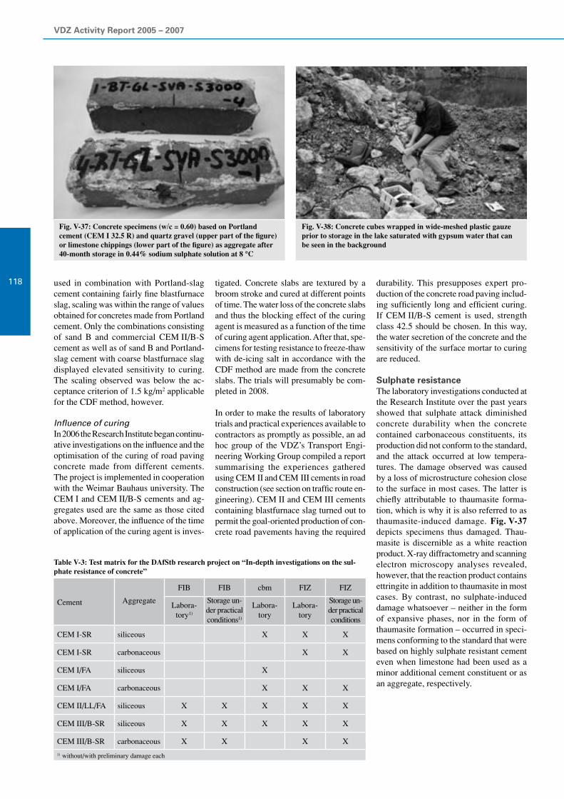
VDZ Activity Report 2005 – 2007
118
Fig. V-37: Concrete specimens (w/c = 0.60) based on Portlandcement (CEM I 32.5 R) and quartz gravel (upper part of the figure) or limestone chippings (lower part of the figure) as aggregate after 40-month storage in 0.44% sodium sulphate solution at 8 °C
Fig. V-38: Concrete cubes wrapped in wide-meshed plastic gauze prior to storage in the lake saturated with gypsum water that can be seen in the background
Table V-3: Test matrix for the DAfStb research project on “In-depth investigations on the sul-phate resistance of concrete”
FIB FIB cbm FIZ FIZ
Cement AggregateLabora-
tory1)
Storage un-der practical conditions1)
Labora-tory
Labora-tory
Storage un-der practical conditions
CEM I-SR siliceous X X X
CEM I-SR carbonaceous X X
CEM I/FA siliceous X
CEM I/FA carbonaceous X X X
CEM II/LL/FA siliceous X X X X X
CEM III/B-SR siliceous X X X X X
CEM III/B-SR carbonaceous X X X X
1) without/with preliminary damage each
used in combination with Portland-slag cement containing fairly fine blastfurnace slag, scaling was within the range of values obtained for concretes made from Portland cement. Only the combinations consisting of sand B and commercial CEM II/B-S cement as well as of sand B and Portland-slag cement with coarse blastfurnace slag displayed elevated sensitivity to curing. The scaling observed was below the ac-ceptance criterion of 1.5 kg/m2 applicable for the CDF method, however.
Influence of curingIn 2006 the Research Institute began continu- ative investigations on the influence and the optimisation of the curing of road paving concrete made from different cements. The project is implemented in cooperation with the Weimar Bauhaus university. The CEM I and CEM II/B-S cements and ag-gregates used are the same as those cited above. Moreover, the influence of the time of application of the curing agent is inves-
tigated. Concrete slabs are textured by a broom stroke and cured at different points of time. The water loss of the concrete slabs and thus the blocking effect of the curing agent is measured as a function of the time of curing agent application. After that, spe-cimens for testing resistance to freeze-thaw with de-icing salt in accordance with the CDF method are made from the concrete slabs. The trials will presumably be com-pleted in 2008.
In order to make the results of laboratory trials and practical experiences available to contractors as promptly as possible, an ad hoc group of the VDZ’s Transport Engi-neering Working Group compiled a report summarising the experiences gathered using CEM II and CEM III cements in road construction (see section on traffic route en-gineering). CEM II and CEM III cements containing blastfurnace slag turned out to permit the goal-oriented production of con-crete road pavements having the required
durability. This presupposes expert pro-duction of the concrete road paving includ- ing sufficiently long and efficient curing. If CEM II/B-S cement is used, strength class 42.5 should be chosen. In this way, the water secretion of the concrete and the sensitivity of the surface mortar to curing are reduced.
Sulphate resistanceThe laboratory investigations conducted at the Research Institute over the past years showed that sulphate attack diminished concrete durability when the concrete contained carbonaceous constituents, its production did not conform to the standard, and the attack occurred at low tempera-tures. The damage observed was caused by a loss of microstructure cohesion close to the surface in most cases. The latter is chiefly attributable to thaumasite forma-tion, which is why it is also referred to as thaumasite-induced damage. Fig. V-37 depicts specimens thus damaged. Thau-masite is discernible as a white reaction product. X-ray diffractometry and scanning electron microscopy analyses revealed, however, that the reaction product contains ettringite in addition to thaumasite in most cases. By contrast, no sulphate-induced damage whatsoever – neither in the form of expansive phases, nor in the form of thaumasite formation – occurred in speci-mens conforming to the standard that were based on highly sulphate resistant cement even when limestone had been used as a minor additional cement constituent or as an aggregate, respectively.

V Concrete constituents, concrete technology and concrete engineering
119
Fig. V-39: Storage of concrete cubes in defined soil material at 8 °C and exposed to external sulphate attack by sodium sulphate solution
Fig. V-40: Corrosion of a steel formwork table
DAfStb special research projectIn its 2005 status report on “Sulphate attack on concrete”, the German Committee for Structural Concrete (DAfStb) stated that the various occurrences of thaumasite-induced damage observed in laboratory trials had been caused by insufficient micro-structure consolidation, i.e. insufficient physical sulphate resistance. This was attributed to high initial porosity due to a water/cement ratio of 0.60, and the reduced reactivity of fly ash at low ambient tempera- tures (< 10 °C).
In order to bring the results of labora-tory investigations in line with practical experiences, the DAfStb initiated a spe-cial research project entitled “In-depth investigations on the sulphate resistance of concrete” in 2006. The project is spon-sored by funds provided by the German Concrete and Construction Engineering Association (DBV), the Federal German Ready-Mixed Concrete Industry Associa- tion (BTB), VGB-Power Tech, and the VDZ. In addition to the Research Institute of the Cement Industry (FIZ), the Building Ma-terials and Materials Testing Centre (cbm) of Munich technical university and the F. A. Finger Institute for Building Materials (FIB) of Weimar university are involved in the research programme. 10x10x10 cm3 concrete specimens will be subjected to storage under practical conditions and to realistic laboratory investigations until the end of 2008. Table V-3 shows the test ma-trix of the research programme. Concretes without fly ash were made with a cement content of 360 kg/m3 and a water/cement ratio of w/c = 0.50, while a cement content of 327 kg/m3, a fly ash content of 82 kg/m3 (k factor k
f = 0.40) and an equivalent water/
cement ratio (w/c)eq
= 0.50 were set for concretes with fly ash. The aggregates
were made up in accordance with grading curve A/B 16. In the concretes containing carbonaceous aggregates, morainic sand accounts for material up to 2 mm and lime-stone chippings for the remainder.
The Research Institute carries out both tests under practical conditions and spe-cial laboratory trials also known as lysim-eter trials. As a suitable site with natural sulphate attack conditions does not even exist within a fairly large radius around Düsseldorf, a gypsum/anhydrite strip mine in Lower Saxony was selected for the tests under practical conditions as an alterna-tive. Fig. V-38 depicts some of a total of 60 concrete specimens that were lowered into a lake saturated with calcium sulphate near Stadtoldendorf. Until the preliminary completion of the project at the end of 2008, the concrete cubes will be examin-ed for sulphate-induced damage twice a year. The investigations are intended to be continued until 2016 if possible in order to gather findings on the long-term behaviour of the concretes under conditions relevant for practical application.
The laboratory trials consist of storing the concrete cubes in defined soil material (Fig. V-39). Sulphate attack is effected by means of sodium sulphate solution with which the soil material is saturated. The soil is drained at regular intervals to be subse-quently filled up with fresh solution again. In this way, natural variations of the ground water table are to be simulated. Carried out at 8 °C, storage is geared to the mean soil temperature in Germany.
The FIB carries out its tests under practical conditions in a gallery drip road in Thurin-gia. The main focus is placed on compara-tive investigations on concrete specimens
with and without preliminary damage by cracking. The cbm deals with the question of whether it is necessary to add fly ash exceeding the minimum dosage presently stipulated to the concrete in order to ensure sufficient sulphate resistance even at low temperatures.
Topical issues regarding corrosionChromate reduction and zinc corrosionSince 17 January 2005, the content of water-soluble chromate in cement or cementitious preparations has been limited to a maximum of 2 ppm by law (“Chromate Directive” 53/2003/EC and Ordinance on Hazardous Substances GefStoffVO). One way of achieving this is to add small quan-tities of chromate-reducing agents as early as during cement manufacture.
When zinc-coated metals (such as zinc-coated steel wire fibres) come into contact with the fresh concrete, surface reactions of the zinc layer and the alkaline medium of the concrete may occur. In individual cases, the formation of gaseous reaction products may impair both the adhesion of concrete and metal and the quality of the concrete surface. Up to now, this reaction was effi-ciently prevented by a sufficient content of soluble chromates. The chromate contained in the cement usually sufficed to obtain this effect. In some cases, chromate salts were added as well when zinc-coated steel fibres were admixed to the concrete. Concrete ad-ditions that result in the chromate content of 2 ppm relative to the cement content in the fresh concrete being exceeded, however, violate the legal regulations cited.
When zinc-coated mounting parts or steel wire fibres are used in concrete, it therefore has to be made sure that material adhesion

VDZ Activity Report 2005 – 2007
120
or the concrete surface are not comprom-ised due to compliance with the legal regu-lations on the chromate content.
Corrosion of steel mouldsThe corrosion of steel moulds is a recur-ring problem in the precast components industry (Fig. V-40). Within the short pe-riod of about twelve hours till formwork removal, rust patches are formed on the surface of the steel formwork tables in some cases. Their appearance can differ vastly. There are punctiform, linear and sometimes even large-surface corrosion areas. The rusty patches frequently occur near the edges, especially in the area round the traverse stops.
The corrosion phenomena are attributable to environmental, production-related and concrete technology reasons. The envi-ronmental reasons include, for example, rusting due to the condensation of water, which preferably occurs when precast concrete elements harden in heated cham-bers or in vapour. As a consequence of the “uplift”, small cracks are formed between the concrete and the steel mould, in which condensation of water leads to corrosion of the steel formwork. Production-related causes chiefly include the inexpert surface processing of the steel moulds, the utilisa-tion of water-soluble marking agents, and the incorrect use of release agents. The con- crete technology causes that may promote rusting chiefly comprise bleeding of the fresh concrete. Given the large variety of causes, the respective underlying conditions usually have to be reviewed individually at each precast components factory. The prob-lem of rust formation can be counteracted both by simple concrete technology and by appropriate process technology measures. It is often enough to simply reduce the supply of contact water on the mould surface by using concrete compositions that have no bleeding tendency. Munich technical university systematically investigated the problem of steel mould corrosion as part of a research project. The investigations were attended by the Research Institute.
Fair-faced concrete
Fair-faced concrete has been enjoying grow-ing popularity. In recent years, building owners and architects have rediscovered concrete surfaces as elements of style and creative expression in modern architecture. Recent examples furnish proof of the re-quirement for smooth fair-faced concrete surfaces of uniform colour having sharp edges. This becomes particularly obvious in representative structures.
Joint research on fair-faced concreteIn spite of expert planning and execution, the current state of knowledge in the do-mains of concrete, moulding and execution technique does not always allow to pur-posefully accomplish immaculate fair-faced concrete surfaces. For that reason, experts from the practical application and scientific communities joined forces to carry out a joint research project on the subject of “Fair-faced concrete”, which is sponsored by the Federation of Industrial Cooperative Research Associations “Otto von Guericke” (AiF). The project was con-ducted under the joint overall responsibility of the German Concrete and Construction Engineering Association (DBV) and the German Cement Works Association (VDZ). Phenomena that might lead to complaints were investigated systematically. These for example include cloud formation, marbling, discoloration, accumulation of pores and „rinse flow streamers“. Accordingly, the main focus of joint research was placed on the formation and prevention of colour deviations on fair-faced concrete surfaces, the interaction of concrete, formwork shell and release agent, the composition and testing of mixes for the production of fair-faced concrete, and the image-aided evalu-ation of fair-faced concrete surfaces.
Research at the Research InstituteThe Research Institute analysed the causes of discoloration and cloud formation on fair-faced concrete surfaces. Attention centred on the influence that super-plas-ticisers and compaction by vibration have on sedimentation behaviour. The Building Materials and Materials Testing Centre of Munich technical university simulta-neously investigated colour phenomena on fair-faced concrete surfaces in terms of transport and crystallisation processes in the hardening concrete.
The results obtained by the Institute’s re-search reveal that the saturation point, i.e. the quantity of super-plasticiser that results in the complete dispersion of the particles,
plays a decisive role in the sedimentation and discoloration of fair-faced concrete surfaces when plasticising admixtures are used. Nearly all discoloration and sedi-mentation phenomena that occurred on fair-faced concrete surfaces and spoiled the optical appearance were observed when quantities of super-plasticiser exceeding the saturation point had been added. This entailed dark and glassy discoloration, cloud formation, marbling, “rinse flow streamers” and water entraining effects.
When super-plasticisers based on polycarb-oxylate ether (PCE) were used, the satu-ration point was reached earlier than with super-plasticisers based on the active ingre-dients melamine sulphonate, naphthalene sulphonate and calcium lignin sulphonate. The cement type was not found to have a systematic impact on the saturation point. The saturation point rather depends on the fineness and the chemico-mineralogical composition of the cement.
The influence that the time and intensity of compaction have on the sedimentation and discoloration of the mortar surface was tested by compacting five mortar cylinders having a diameter of approx. 30 mm and a height of approx. 200 mm on a vibrating table. When super-plasticiser dosage was below the saturation point, all cement/addi-tion/super-plasticiser combinations yielded sedimentation-free mortar without signifi-cant discoloration.
Fig. V-41 shows a total of 10 mortar cy-linders. The mortar was made up of ap-prox. one proportion CEM II/B-S 32.5 R, approx. 0.2 proportions hard coal fly ash and approx. 1.1 proportions Visco stand-ard sand (particle size ≤ 1 mm) by mass each. The equivalent water/cement ratio was 0.45. The mortar contained a 1.5-fold overdose of melamine sulphonate (left-hand photo) and PCE super-plasticiser (right-hand photo) relative to the saturation point. The respective first cylinders were not compacted after filling. Cylinders two and three, respectively, were compacted on the vibrating table at a vibration amplitude of 0.75 mm for 60 and 120 seconds, respec-tively. Cylinders four and five, respectively, were compacted at a vibration amplitude of 1.3 mm for 60 and 120 seconds, re-spectively.
The mortar cylinders were removed after seven days. After another 21 days of stor-age at 20 °C and 65% relative humidity, the surface was assessed visually. The cement/addition/super-plasticiser combinations that did not exhibit any manifestation of

V Concrete constituents, concrete technology and concrete engineering
121
Fig. V-41: Mortar cylinders (diameter 30 mm, height 200 mm), cylinder 1 = not compacted; cylinders 2 and 3, respectively, compacted at a vibration amplitude s = 0.75 mm for 60 and 120 seconds, respectively; cylinders 4 and 5, respectively, compacted at a vibration amplitude s = 1.3 mm for 60 and 120 seconds, respectively; 1.5-fold overdose of the respective super-plasticisers relative to the saturation point; plasticisers based on melamine sulphonate (left-hand photo) and PCE (right-hand photo)
sedimentation or discoloration in spite of a 1.5-fold overdose of super-plasticiser rela-tive to the saturation point were referred to as “very robust”. The combinations that, regardless of all compaction parameters, were resistant to sedimentation and did not exhibit any discoloration at the “saturation point” were classified as “robust”. When the behaviour of cement/addition/super-plasticiser combinations was stable at the saturation point only in case of short-time and low-intensity compaction or only be-low the saturation point, respectively, they were assigned to the “little robust” or “not robust” categories, respectively.
As can be seen from the left-hand photo of Fig. V-41, the cylinders containing melamine sulphonate had a homogeneous surface without sedimentation and discol-oration in spite of overdose and regardless of the time and intensity of compaction. This “very robust” behaviour was recorded for nearly all mortars containing super-plasticiser based on melamine sulphonate, regardless of the cement type.
The super-plasticiser based on PCE yielded “very robust” mortars in terms of sedi-mentation behaviour in many cases. As becomes evident from the right-hand photo in Fig. V-41, however, the use of PCE oc-casionally also yielded mortars classified as “not robust”. These were characterised by marked sedimentation, i.e. by the dis-persed constituents settling in accordance with particle size and mass, which was always accompanied by intense discolora-tion. The behaviour of mortars containing super-plasticisers based on naphthalene sulphonate ranged from “little robust” to “robust”. Mortars and concretes made from Portland cement or Portland-limestone cement, respectively, displayed “robust” or “very robust” sedimentation behaviour regardless of the type of super-plasticiser, which reflects practical experiences. The sedimentation phenomena and discolora-tion recorded in the case of some cements containing blastfurnace slag are studied in a further research project.
Mortars characterised by super-plasticiser dosage at and exceeding the saturation point always looked darker than mortars with lower super-plasticiser content.
The saturation points of the respective test concretes were higher than those of the corresponding mortars. Mortars found to be stable in the sedimentation test were always resistant to sedimentation in the concrete as well. The method of compaction (internal vibration or vibrating table) did not have
any significant influence on sedimenta-tion behaviour and concrete compressive strength. As a tendency, compaction on the vibrating table resulted in slightly fas-ter deaeration of concrete. In comparison to the impact of super-plasticiser dosage, the influence of the method, duration and intensity of compaction on sedimentation behaviour was of subordinate importance. The sedimentation phenomena observed in the concretes containing high super-plasticiser quantities were restricted to the immediate concrete surface.
Fig. V-42 is a schematic representation of the influence that the quantity of super-plas-ticiser relative to the saturation point has on the sedimentation behaviour and the cement paste structure on the concrete surface. The photos depict surfaces of concretes con-taining corresponding quantities of super-plasticiser. The effects of super-plasticiser dosage on hydration, the composition of the pore solution and the hydrate phases are described as possible causes of the sedi-mentation phenomena and discolorations observed on fair-faced concrete surfaces.
Super-plasticiser quantities (FM) far below the saturation point (SP) of concretes (FM << SP) usually retard hydration only slight-ly and generally do not lead to sedimenta-tion in concretes of ordinary composition. The concrete surface is primarily made up of CSH phases and calcium carbonate. The coloration of the surface is homogeneous (Fig. V-42, line 1).
If super-plasticiser dosage ranges around the saturation point (FM = SP, Fig. V-42, line 2), most cement particles are coated by super-plasticiser molecules and present in dispersed form. Depending on the water/ solids ratio, these systems are still stable with regard to sedimentation. As the cement surface gets more and more coated by super- plasticiser molecules, further cement hydration is retarded increasingly. Within the retardation period, the contents of dissolved calcium and sulphate, among others, remain at their initial level. When hydration is not retarded, by contrast, they decrease considerably within a few hours as a consequence of progressing ettringite formation. Retardation may lead to an ac-cumulation of pore solution between the fresh concrete and the mould as a result of hydrostatic pressure or minor movements of the mould, for example. In case of a minor accumulation of pore solution it is consumed as the cement hydration pro-gresses, leaving behind a nearly amorphous calcium hydroxide layer. Some of the hy-dration products in this layer are smaller than the wavelength of light. This leads to specular reflection of incident light, which is an explanation for the shining surface of the concrete. These areas appear darker than the coarser areas containing larger crystallites.
Super-plasticiser dosage above the satur-ation point (FM > SP, Fig. V-42, line 3) leads to marked sedimentation and con-siderable retardation of hydration. In this

VDZ Activity Report 2005 – 2007
122
Super-plasticiser dosage View – fair-faced concrete Effect
1
FM << SP
Hydration: slightly retarded
Sedimentation tendency: very low (very stable)
Pore solution: no accumulation of pore solution between the fresh concrete and the formwork, rapid decrease of the cal-cium and sulphate contents in the pore solution by hydration
Surface: CSH phases, CaCO3
Surface colour: “grey” (rough structure)
2
FM = SP
Hydration: retarded
Sedimentation tendency: low (stable)
Pore solution: slight accumulation of pore solution between the fresh concrete and the formwork, high calcium and sulphate contents in the pore solution during the retardation period
Surface: amorphous Ca(OH)2 layer
Surface colour: dark (glassy structure)
3
FM > SP Hydration: considerably retarded
Sedimentation tendency: high (instable), settling sedimen-tation
Pore solution: marked accumulation of pore solution between the fresh concrete and the formwork is possible, high calcium and sulphate contents in the pore solution during the retardation period
Surface: Depending on the constituent settled, the settling sedimentation can result in surfaces of varying compositionbottom section: “rinse flow streamers” – e.g. sand, CSH phasesmiddle section: amorphous Ca(OH)
2 layer
top section: CSH phases (large crystals)
Surface colour:bottom section: bright texturemiddle section: dark, glassytop section: very bright
Fig. V-42: Influence of the super-plasticiser quantity (FM) in relation to the saturation point (SP) on sedimentation behaviour, cement hydra-tion and possible effects on the composition and colour of the fair-faced concrete surface
-
-
-
- -
-
--
-
--
-- -
--- --
-+
-+
- -- -
+-- + +
+
+-
- - -
-
-
+--
+-+
- -- - -
+--
+--
-++-
-- -
++
---
--
+--
- - -+--
+-+
--
- -+ +- -
-
++
++
--
-
- - -
-+
++
---
-
--
+
---
--
+
+
- --
-
--
--
- -
- ++
- --
+ +
+
+-
-- -
- -+
+- --
-
--
+--
-
-
+ -
+
+
+
- - +
- -
+
-++ +
+-
- - --
-++ +
+-
- - -
-
+++
+
-
-
- -
--
- -
-- - -
---
-
--
-
- - -- --
- -
--
- - --
- - --
- - --
-- - -
- -
-- - -
- - -- -
-
---
- --
- - -
-- - -
--
-
- - -
-- -- -
--
--
--
--- -
-
- -
+--
+ +
+
+-
- - -
- ---
+--+
--
+--
-++-
- ---
++
---
-
+--
+-
+ --- - -
-- -+ +- -
-
++
+
+
---
-
- - - -+
++
---
-
---
+
---
--
+
+
- --
-
-----+
+++-
-
- -
--
- -
- ++
- --
+ +
+
+-
-- -
--
- -
-
--++ +
+-
- - --
+
+- -- -
- -
- -++-
- -
+
-+
- -+ +- -
-
+
--
+
+ +
-
-
- -
+ -
- -
- --
- -
- -- - -
- - -
- - -- - ---
- ---
- --
---
--
- - --
--
--
--
-
--
- - - -
- - - ---
- --
- - --
-
-- -
--- -
+-
+--
+-
-++-
-- -
++
--- - -
+ --- - -
+--
-+ --- -
- -+ +- -
-
+ +
++
-- - -
-+
+- ---
-
-- - +
+
-++ +
+-
- - --
-++ +
+-
- - --
-
- -
--
-- -
----
---
- - -- --
- -
--
- - --- - - - -
-- - -
-
-- -++
--++
+ +
+
+- - - -
+
+
-+- -+
--
- -
- ++
+
+
- --
-+
++
---
---
+
---
-- -
- -
+
+- -
-
+
++
-
-
-- -
--
-
--+
--
-
-
-
-
- -
-
--
-
--
-- -
--- --
-+
-+
- -- -
+-- + +
+
+-
- - -
-
-
+--
+-+
- -- - -
+--
+--
-++-
-- -
++
---
--
+--
- - -+--
+-+
--
- -+ +- -
-
++
++
--
-
- - -
-+
++
---
-
--
+
---
--
+
+
- --
-
--
--
- -
- ++
- --
+ +
+
+-
-- -
- -+
+- --
-
--
+--
-
-
+ -
+
+
+
- - +
- -
+
-++ +
+-
- - --
-++ +
+-
- - -
-
+++
+
-
-
- -
--
- -
-- - -
---
-
--
-
- - -- --
- -
--
- - --
- - --
- - --
-- - -
- -
-- - -
- - -- -
-
---
- --
- - -
-- - -
--
-
- - -
-- -- -
--
--
--
--- -
-
- -
+--
+ +
+
+-
- - -
- ---
+--+
--
+--
-++-
- ---
++
---
-
+--
+-
+ --- - -
-- -+ +- -
-
++
+
+
---
-
- - - -+
++
---
-
---
+
---
--
+
+
- --
-
-----+
+++-
-
- -
--
- -
- ++
- --
+ +
+
+-
-- -
--
- -
-
--++ +
+-
- - --
+
+- -- -
- -
- -++-
- -
+
-+
- -+ +- -
-
+
--
+
+ +
-
-
- -
+ -
- -
- --
- -
- -- - -
- - -
- - -- - ---
- ---
- --
---
--
- - --
--
--
--
-
--
- - - -
- - - ---
- --
- - --
-
-- -
--- -
+-
+--
+-
-++-
-- -
++
--- - -
+ --- - -
+--
-+ --- -
- -+ +- -
-
+ +
++
-- - -
-+
+- ---
-
-- - +
+
-++ +
+-
- - --
-++ +
+-
- - --
-
- -
--
-- -
----
---
- - -- --
- -
--
- - --- - - - -
-- - -
-
-- -++
--++
+ +
+
+- - - -
+
+
-+- -+
--
- -
- ++
+
+
- --
-+
++
---
---
+
---
-- -
- -
+
+- -
-
+
++
-
-
-- -
--
-
--+
--
-

V Concrete constituents, concrete technology and concrete engineering
123
Fig. V-43: Test under practi-cal conditions – pouring of a test wall with SCC
case, the water/cement ratio in the upper section of the sedimentation area, in which primarily the fine particles of the binder are deposited, can be lower than in the bottom section where chiefly coarse constituents, such as gravel and sand, are found. This would explain why “rinse flow streamers” frequently occur in the bottom sections of the areas affected by sedimentation. In addition to fine aggregates, the “rinse flow streamers” contain large crystallites of hy-drate phases that appear as light texture. The section in the middle often appears darker, which is attributable to a layer of amorphous calcium hydroxide. The upper section is made up of a loose structure of fully hydrated cement particles which were hydrated in floating. Some of the crystalli-tes of which can take idiomorphous form, thus appearing as a nearly white layer.
Surface sedimentation can also occur in the case of concretes containing a dosage of super-plasticiser just below the satura-tion point if pore solution can accumulate between the fresh concrete and the mould. The accumulation of pore solution leads to a subsequent rise in the water/cement ratio near the surface. As a consequence, the saturation point of the super-plasticiser in these areas may be lowered to such an extent as to enable sedimentation. This explains the surface sedimentation often observed on concrete columns although the cross-section of the concrete is nearly homogeneous.
Basically, the risk of surface sedimentation and discoloration can be diminished by applying concretes with very low water secretion. The quantity of super-plasticiser added should be far below the saturation point, and the grading curve should be well-graded and contain a high proportion of fines. Mould vibrations, which might result in suction effects after placing in the fresh concrete phase and thus in a build-up of pore solution between the fresh concrete and the mould, should be prevented.
Self-compacting concrete
Self-compacting concrete (SCC) is a high-performance concrete the distinctive performance feature of which consists of the fresh concrete property of “self-com-paction”. In addition to its vast potential for streamlining the production of precast con-crete elements, it also presents advantages for the course of construction at building sites. To benefit from these advantages, ut-most diligence in manufacture and quality assurance is indispensable.
The influences on the properties of fresh and hardened self-compacting concrete were investigated under the terms of a joint research project of the Research Associa-tion for Ready-Mixed Concrete (FTB) in Kamp-Lintfort and the Research Institute. The aim pursued was to safely allow the production and application of SCC as ready-mixed concrete of strength classes C 25/30 and C 30/37 while using typical plants and raw materials. On the one hand, the results showed that the purposeful ad-justment of water and super-plasticiser con-tents allows the very precise time control of workability properties. On the other hand, they highlighted that variations in the water and super-plasticiser contents have to be
monitored very closely and compensated by appropriate measures if necessary. The investigation results underscored the im-portance of meticulously planned prelimi-nary trials as well as initial and control testing in the production and processing of SCC as ready-mixed concrete.
To test the results obtained for labora- tory-made concretes under practical condi-tions, the properties of fresh and hardened self-compacting concrete produced in two ready-mixed concrete works were investi-gated. Test walls were subsequently poured from concretes containing the material combinations blastfurnace cement/hard coal fly ash and Portland cement/limestone meal (Fig. V-43).
Based on the results obtained, a concept for assessing the workability of SCC under practical conditions was elaborated. Fixed limit values or workability classes are not suitable for capturing the workability characteristics of SCC properly. Carrying out tests of fresh and hardened concrete in the wake of mixture development and initial testing, concrete manufacturers de-termine the optimum workability range for their SCC. Adequate flowing, air evacua-tion and sedimentation stability of the con-

VDZ Activity Report 2005 – 2007
124
Fig. V-44: On-site use of the VDZ flow cone for determining the fresh con-crete properties of SCC
crete constitute the features characterising an optimum workability range. A method for determining the workability range of SCC (“SCC workability window”) was proposed to lay down uniform rules and evaluation standards for all types of SCC. This method was developed, verified and validated on the basis of numerous inves-tigations. It was incorporated in the “Self-compacting concrete” guidelines of the German Committee for Structural Concrete as Annex Q.
To assess the workability of SCC, it is required to determine the slump flow measure and the V-funnel flow time during factory production control by the manuf-acturer and when the concrete is delivered on site. The determination of the V-fun-nel flow time under site conditions often causes problems when SCC is delivered as ready-mixed concrete. To reduce the cost and effort involved in testing when SCC is delivered in the form of ready-mixed concrete, the “flow cone” (Fig. V-44) was developed. It represents a testing device suited for on-site use that allows reliabe determination of the two test values (slump flow measure and V-funnel flow time) in one single trial.
This research work made a major contribu-tion to the application of SCC in the form of ready-mixed concrete in accordance with EN 206-1 / DIN 1045-2 in combination with the DAfStb‘s SCC guidelines as an alternative to vibrated concrete that safely meets quality requirements.
Ultra high performance concrete
Ultra high performance concrete (UHPC) constitutes a further development of high-strength concrete. Concretes having com-pressive strengths between approx. 150 and 300 N/mm2 are given the attribute “ultra-high performance”. Acknowledged regulations for UHPC do not yet exist in Germany. A key programme of the German Research Foundation (DFG) is aimed at extensively exploring all major aspects of UHPC production and application. The way of reliably achieving compressive strengths of more than 150 N/mm2 has been largely known by now. Compressive strengths of up to approx. 200 N/mm2 can be attained by consistently applying the concrete tech-nology measures for increasing strength – lowering the water/cement ratio, using silica fume and optimising packing density right down to the micro range – which are already known from high-strength con-crete. Even higher strengths can be attained by additional measures, which largely include thermal treatment, mixing in a vacuum and pressure compaction. The most common kind of thermal treatment consists of storing the concrete in hot air at 90 °C for 48 hours following two-day preliminary storage. It has almost reached its final strength afterwards. Considerably less air can enter the fresh concrete when it is mixed in a vacuum, while subsequent air evacuation by vibrating is less effec-tive due to the often gluey consistency of
UHPC. Little experience has been gathered on pressure compaction to date. In this pro-cess, the moulded concrete sets and hardens while subjected to compressive load.
DurabilityUHPC is considered very durable. Both to-tal and capillary porosity, which is decisive for transport processes, are considerably lower than with normal-strength and high-strength concrete. Typical carbonation depth after one year, for example, totals less than 0.1 mm.
Corresponding investigations are, however, usually carried out on specimens that have not suffered damage. It is unclear whether the durability of UPHC can be reduced by cracks. The effects of possible expansive reactions on the extremely dense UHPC microstructure in particular have not yet been explored adequately.
Crack formation as a consequence of restraint to shrinkage deformationIn addition to temperature expansion and bending tensile stress, the possible causes of cracking chiefly include restraint to shrinkage deformation. Autogenous shrink- age, which occurs without moisture being released to the ambient air, is particularly marked with UHPC. In contrast to drying shrinkage, it usually increases in line with a drop in the water/cement ratio. If a major part of the cement is unhydrated due to a lack of water, internal drying also called “self-desiccation” ensues. The negative pressure thus generated in the fully or partly desiccated pores is so high that the hardened cement paste contracts. Restraint to this contraction, which may be caused by aggregates or an adjacent structural element, results in stresses in the concrete, which may in turn lead to cracks.
Possible damage mechanismsCracks allow liquids and gases to penetrate the concrete and cause various damage mechanisms. If water penetrates the UHPC microstructure, the cracks undergo self-healing by subsequent hydration under the most favourable of circumstances. Under adverse conditions, various damage mecha-nisms are conceivable, such as secondary ettringite formation or alkali-silica reac-tion. Both reactions can cause expansive pressure detrimental to the concrete, thus reducing concrete durability.
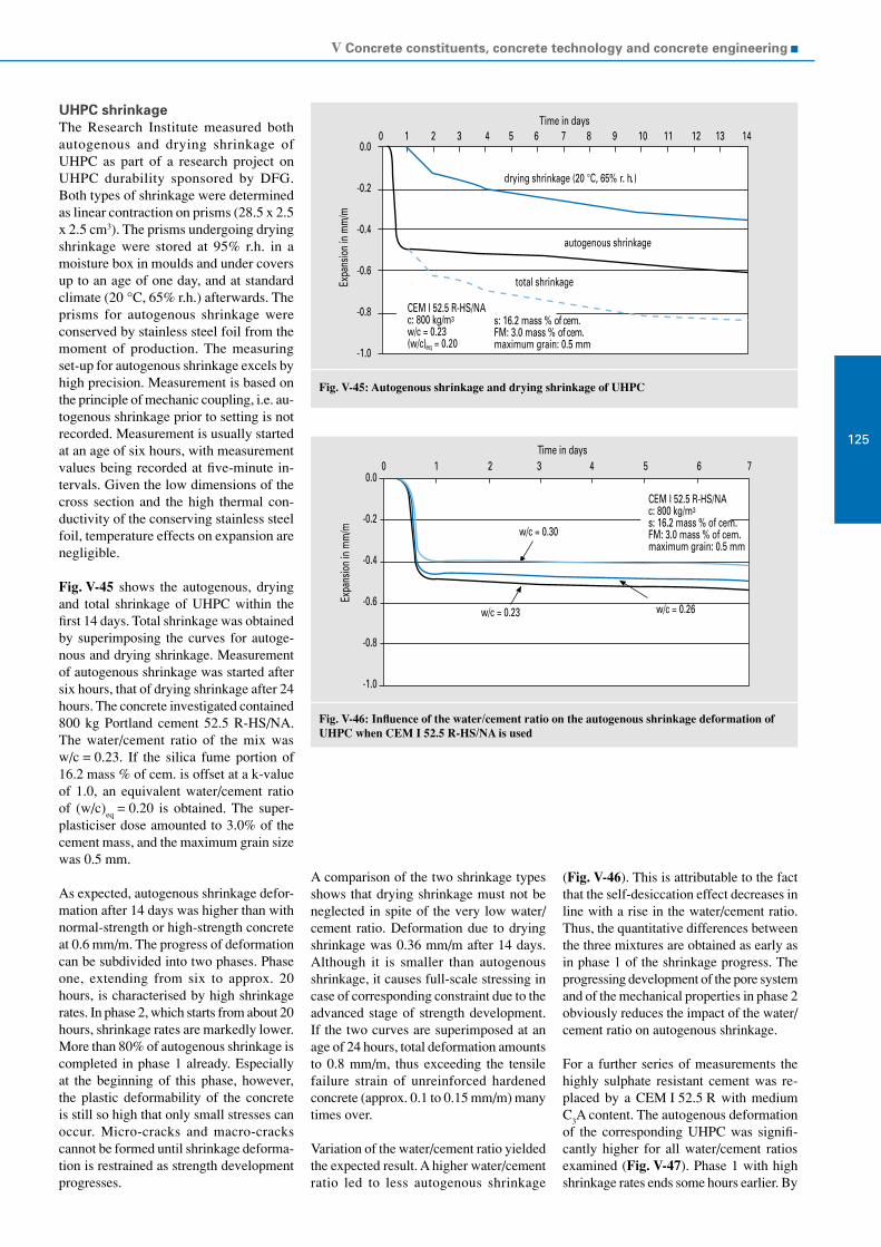
V Concrete constituents, concrete technology and concrete engineering
125
Fig. V-45: Autogenous shrinkage and drying shrinkage of UHPC
Fig. V-46: Influence of the water/cement ratio on the autogenous shrinkage deformation of UHPC when CEM I 52.5 R-HS/NA is used
CEM I 52.5 R-HS/NAc: 800 kg/m3
w/c = 0.23(w/c)eq = 0.20
0.0
-0.2
-0.4
-0.6
-0.8
-1.0Ex
pans
ion
in m
m/m
0 1 2 3 4 5 6 7 8 9 10 11 12 13 14Time in days
s: 16.2 mass % of cem.FM: 3.0 mass % of cem.maximum grain: 0.5 mm
total shrinkage
drying shrinkage (20 °C, 65% r. h.)
autogenous shrinkage
0.0
-0.2
-0.4
-0.6
-0.8
-1.0
Expa
nsio
n in
mm
/m
0 1 2 3 4 5 6 7Time in days
CEM I 52.5 R-HS/NAc: 800 kg/m3
s: 16.2 mass % of cem.FM: 3.0 mass % of cem.maximum grain: 0.5 mm
w/c = 0.30
w/c = 0.23 w/c = 0.26
UHPC shrinkageThe Research Institute measured both autogenous and drying shrinkage of UHPC as part of a research project on UHPC durability sponsored by DFG. Both types of shrinkage were determined as linear contraction on prisms (28.5 x 2.5 x 2.5 cm3). The prisms undergoing drying shrinkage were stored at 95% r.h. in a moisture box in moulds and under covers up to an age of one day, and at standard climate (20 °C, 65% r.h.) afterwards. The prisms for autogenous shrinkage were conserved by stainless steel foil from the moment of production. The measuring set-up for autogenous shrinkage excels by high precision. Measurement is based on the principle of mechanic coupling, i.e. au-togenous shrinkage prior to setting is not recorded. Measurement is usually started at an age of six hours, with measurement values being recorded at five-minute in-tervals. Given the low dimensions of the cross section and the high thermal con-ductivity of the conserving stainless steel foil, temperature effects on expansion are negligible.
Fig. V-45 shows the autogenous, drying and total shrinkage of UHPC within the first 14 days. Total shrinkage was obtained by superimposing the curves for autoge-nous and drying shrinkage. Measurement of autogenous shrinkage was started after six hours, that of drying shrinkage after 24 hours. The concrete investigated contained 800 kg Portland cement 52.5 R-HS/NA. The water/cement ratio of the mix was w/c = 0.23. If the silica fume portion of 16.2 mass % of cem. is offset at a k-value of 1.0, an equivalent water/cement ratio of (w/c)
eq = 0.20 is obtained. The super-
plasticiser dose amounted to 3.0% of the cement mass, and the maximum grain size was 0.5 mm.
As expected, autogenous shrinkage defor-mation after 14 days was higher than with normal-strength or high-strength concrete at 0.6 mm/m. The progress of deformation can be subdivided into two phases. Phase one, extending from six to approx. 20 hours, is characterised by high shrinkage rates. In phase 2, which starts from about 20 hours, shrinkage rates are markedly lower. More than 80% of autogenous shrinkage is completed in phase 1 already. Especially at the beginning of this phase, however, the plastic deformability of the concrete is still so high that only small stresses can occur. Micro-cracks and macro-cracks cannot be formed until shrinkage deforma-tion is restrained as strength development progresses.
A comparison of the two shrinkage types shows that drying shrinkage must not be neglected in spite of the very low water/cement ratio. Deformation due to drying shrinkage was 0.36 mm/m after 14 days. Although it is smaller than autogenous shrinkage, it causes full-scale stressing in case of corresponding constraint due to the advanced stage of strength development. If the two curves are superimposed at an age of 24 hours, total deformation amounts to 0.8 mm/m, thus exceeding the tensile failure strain of unreinforced hardened concrete (approx. 0.1 to 0.15 mm/m) many times over.
Variation of the water/cement ratio yielded the expected result. A higher water/cement ratio led to less autogenous shrinkage
(Fig. V-46). This is attributable to the fact that the self-desiccation effect decreases in line with a rise in the water/cement ratio. Thus, the quantitative differences between the three mixtures are obtained as early as in phase 1 of the shrinkage progress. The progressing development of the pore system and of the mechanical properties in phase 2 obviously reduces the impact of the water/cement ratio on autogenous shrinkage.
For a further series of measurements the highly sulphate resistant cement was re-placed by a CEM I 52.5 R with medium C
3A content. The autogenous deformation
of the corresponding UHPC was signifi-cantly higher for all water/cement ratios examined (Fig. V-47). Phase 1 with high shrinkage rates ends some hours earlier. By

VDZ Activity Report 2005 – 2007
126
Fig. V-47: Influence of the water/cement ratio on the autogenous shrinkage deformation of UHPC when CEM I 52.5 R with a C3A content of 8.5 mass % is used
0.0
-0.2
-0.4
-0.6
-0.8
-1.0
Expa
nsio
n in
mm
/m
0 1 2 3 4 5 6 7Time in days
w/c = 0.30w/c = 0.23
w/c = 0.26
CEM I 52.5 Rc: 800 kg/m3
s: 16.2 mass % of cem.FM: 3.0 mass % of cem.maximum grain: 0.5 mm
contrast, the shrinkage rate at the beginning of phase 2 is higher. Instead of 80%, a mere 65% of deformation is reached in phase 1. In this case, the highest shrinkage rate is not obtained at the lowest water/cement ra-tio investigated. Rather, the shrinkage rate of the mix having a water/cement ratio of w/c = 0.23 is roughly the same as for a wa-ter/cement ratio of w/c = 0.30. The cause of this result is still being explored.
ProspectsIn order to quantify the cracking potential due to the restraint to shrinkage defor-mation, annular concrete specimens the shrinkage deformation of which will be restrained by a steel ring will be produced in the further course of the research pro-ject. In this process, the compression set of the steel ring is measured by a wire strain gauge applied on its inside. This allows determining the time of cracking, among other things.
Specimens that have suffered varying degrees of preliminary damage are then investigated for possible secondary dam-age by expansive reactions following corresponding storage. The main focus is placed on secondary ettringite formation and alkali-silica reaction. Moreover, the investigations cover the possible self- healing of cracks.
Earth-dry concrete
Earth-dry concrete is applied in road con-struction products, such as paving blocks, slabs, curbstones or concrete pipes. In stationary production facilities of the con-crete plants the dry concrete mixes are compacted in rigid steel moulds by inten-sive vibratory/compressive compaction so thoroughly that the products can be de-moulded immediately, retaining their shape due to what is known as green stability. If the concrete composition is appropriate, the concretes compacted in this way achieve the working properties required, such as high strength and density as well as ad-equate durability, for example with regard to exposure to freeze-thaw with de-icing salt or chemical attack.
Brown discolorationBrown discoloration can occur on the concrete surfaces of road construction products made from earth-dry concrete. When it is marked, it can disturb the colour appearance, thus causing damage to the product image.
In the period under review, the “Brown discoloration” industrial discussion panel, on which members of the cement industry and manufacturers of precast concrete products are represented, further explored the complex material and physical causes for brown discoloration. As a result, the occurrence of such discoloration was eliminated in many cases. The “Brown discoloration” discussion panel further elaborated a paper giving advice on how to reduce the risk of brown discoloration in precast concrete products. It summa-rises the current state of knowledge and
the experience available on the subject of brown discoloration. Based on a detailed explanation of the parameters presently known to influence the occurrence of brown discoloration, ways of reducing the risk of brown discoloration are outlined. These include chemico-mineralogical in-fluencing parameters, such as
soluble iron compounds Fe(II) and Fe(III),
high pH value of the pore solution and
complexing reactions between iron compounds and admixtures.
Production, curing, storage and placing in-fluence the physical parameters, such as
porosity/pore size distribution, moisture conditions and solution transport.
The information paper comprises a ques-tionnaire for comprehensive and objective case analysis, which is usually indispens-able for solving problems. This allows the systematic compilation of the relevant material and production-related param-eters and the deduction of risk reduction measures in each individual case.
Awareness of the problem and the willing-ness to engage in dialogue to find solutions obviously led to the result that brown discol- orations were reported only occasionally in 2005/2006. The discussion panel will extrapolate the information paper as soon as new experiences and findings are availa-ble.
Traffic route engineering
High load-bearing capacity and deformati-on stability, low maintenance cost and long service life, high traffic security due to skid resistance and brightness of the surface as well as low noise emission constitute advantageous properties of concrete pa-vements in road construction. Against the backdrop of the beginning introduction of Public Private Partnership agreements, in which responsibility for the construction and maintenance of a road is assigned to a contractor, and continually rising traffic loads on trunk roads in the aftermath of EU enlargement to the east, these criteria have gained ever greater importance.
Topics relating to the durability and surface properties of concrete road paving in par-ticular thus constituted focal points of the Research Institute’s activities in the period under review.

V Concrete constituents, concrete technology and concrete engineering
127
Fig. V-48: Ex-posed aggregate concrete for highways ex-posed to high traffic loads
Exposed aggregate concrete in road constructionProduction of a concrete pavement char-acterised by durably high skid resistance and low noise emission has become one of the foremost tasks in concrete road construction.
In concrete road paving production, the finisher must accomplish an even and uni-form surface in order to reduce the stimu-lation of tyre vibration and the associated noise emission. In order to possess suffi- cient grip, the surface simultaneously has to exhibit texture engraved during production. This additionally prevents air from being compressed between the tyre and the road surface, which escapes with a hissing sound as the tyre rolls off. This texture was previ-ously generated in Germany by engraving a structure into the fresh surface mortar, which was effected by the lengthwise scree-ding of the fresh concrete with a jute cloth, among other techniques. In the past years, the texture was found to have changed after only fairly short exposure to traffic load in individual cases. This change, which was due to insufficient durability of the surface mortar, resulted in a drop in skid resistance. The production of an exposed aggregate concrete surface represents an alternative to texturing the fresh concrete surface. This process consists of purposefully removing the surface mortar and thus establishing the final state of the concrete surface (Fig. V-48). In Germany, this type of construction was only applied on individual test and trial sections so far. In other countries, by contrast, exposed aggregate concrete road paving characterised by long-term low noise emission and high skid resistance has been laid for quite some time.
The influence of different road surfaces on the noise emission caused by traffic is determined on the basis of measurements conducted over many years and described by relative correction values. The road surfaces are classified as more silent (-) or louder (+) in comparison to a reference pavement taken as a reference basis. Stand-ard concrete construction according to the supplementary technical terms of contract and guidelines for concrete (ZTV Beton), which consists of lengthwise texturing by trailing a jute cloth, was classified as noise reducing so far (relative correction value of -2 dB(A)). Only open-pore construction is more silent. A corresponding correction value for exposed aggregate concrete was not available until recently.
Many years of noise measurements carried out on various exposed aggregate concrete pavements furnished proof that exposed aggregate concrete can also be classified as noise-reducing, having a relative correction value of -2 dB(A). This value was laid down in the General circular on road construction No. 5/2006 issued by the Federal Minister for Transport, Building and Urban Deve-lopment. The investigations also revealed that the skid resistance of concrete paving having an exposed aggregate surface is durably high. To take advantage of the skid resistance-related gain in security inherent in exposed aggregate concrete, the previous standard construction involving lengthwise texturing by jute cloth was therefore re-tracted and replaced by concrete paving with exposed aggregate concrete surface.
The top and bottom layer concrete is spread, compacted and smoothed in the usual fashion in exposed aggregate concrete construction. The top course concrete has a maximum grain size of 8 mm and a thick-ness of 4 to 5 cm. Two varieties are applied to produce the exposed aggregate concrete structure. For one thing, a combined retar-ding and curing agent is sprayed on, which retards the hydration of the cement in the layer near the surface and simultaneously prevents the fresh concrete from drying out. Alternatively, a set retarding admix-ture is sprayed on after smoothing and the concrete is covered with plastic sheeting for curing. As soon as the concrete has hardened sufficiently and is fit for traffic, the surface mortar that has not hardened is brushed off and removed by machines. An ordinary curing agent is then sprayed on for further curing.
As concrete paving with exposed aggregate concrete surface has not been covered by the regu-lations for concrete road construc-tion (ZTV-Beton StB 01) yet, correspon-ding specifications were laid down in the General Circular On Road Construction No. 14/2006. The top course concrete is usually made up of fine aggregates 0/2 mm and high-grade chippings of grading 5/8 mm. In order to ensure the good grip properties of the exposed aggregate concrete pavements in the long run, the aggregates have to meet higher requirements. The coarse aggregates 5/8 mm must be crushed. The high degree of roughness of the fully crushed surfaces improves skid resistance. The aggregates additionally have to possess high resistance to polishing. The cement content is increas-ed to a minimum of 420 kg/m3 as against 340 kg/m3 for ordinary road paving con-crete (TL Beton StB 06).
The Research Institute has contributed to ensuring the durability of exposed ag-gregate concrete construction. In an AiF research project applied for, carefully directed investigations on the resistance to freeze-thaw with de-icing salt and the prevention of a harmful alkali-silica reac-tion are to be conducted. The effect of set retarding admixtures, the elevated cement content and the exposed position of the stone chips in exposed aggregate concrete have to be taken into account.
Alkali-silica reactionThe service life of a concrete pavement generally exceeds 30 years. Some concrete road pavements suffered premature dam-age that was attributable to an alkali-silica reaction (ASR) to some extent (see section

VDZ Activity Report 2005 – 2007
128
Table V-4: Alkali content given as Na2O equivalent (characteristic value) of cements used in the construction of concrete road pavements
Cement Blastfurnace slag content
mass %
Alkali content of the cement given as Na
2O
equivalent
mass %
Alkali content of the cement not containing
blastfurnace slag or oil shale, given as Na
2O equivalent mass %
CEM I + CEM II/A ≤ 0.80 -
CEM II/B-T - ≤ 0.90
CEM II/B-S 21 to 29 - ≤ 0.90
CEM II/B-S 30 to 35 - ≤ 1.00
CEM III/A 36 to 50 - ≤ 1.05
Fig. V-49: Ex-pansion of the drill cores as a function of the Na2O equivalent of the cement used and of the duration of 40 °C fog cham-ber storage
Fig. V-50: Damaged and damage-free concrete paving segments con-taining crushed greywacke chip-pings as a func-tion of the Na2O equivalent of the road paving cement
1.00
0.90
0.80
0.70
0.60
0.50
0.40
1 2 3 4 5 6 7 8 9 10 11
Na2O
equi
valen
t in
the c
emen
t in
mas
s %
Construction segments containing greywacke chippings
no damage damage
1.0
0.8
0.5
0.3
0.00 50 100 150 200 250 300 350 400
Expa
nsio
n in
mm
/m
segment 10 (Na2Oeq 0.88 wt.%)
segment 7 (Na2Oeq 0.78 wt.%)
Duration of 40 C fog chamber storage in days
segment 2 (Na2Oeq 0.51 wt.%)
on alkali-silica reaction). The effective alkali content of road paving cement was lowered by Circular No. 12/2006 (Table V-4) in order to preventively ensure a high degree of safety against a harmful ASR in concrete paving. The circular further spe-cifies that crushed aggregates made from greywacke, quartz porphyry and high-grade gravel chippings from the Upper Rhine region as well as imported crushed and recycled aggregates may only be used in concrete road pavements upon presentation of an expertise attesting to the respective supplier works that the rock is suited for the intended purpose. The Research Institute of the Cement Industry and three further bodies are approved for issuing such expert opinios.
Previous investigations, which were prima-rily conducted on drill cores, did not allow ascertainment as to whether the damage to the highways was chiefly caused by an ASR or by several damage mechanisms taking place at the same time. A research project initiated by the Federal Ministry for Trans-port, Building and Urban Development (BMVBS) in which the Research Institute is involved serves to settle this question. The Research Institute evaluated the con-struction records of eleven paving segments of the A 40 and A 61 highways. When they were built some 15 years ago, greywacke chippings now classified as reactive were used. Drill cores were taken from some paving segments. The expansion of the drill cores under different storage conditions (40 °C fog chamber, 60 °C test method with and without external alkali supply) was de-termined. Moreover, thin polished sections were analysed (see section on alkali-silica reaction, petrography) and the construction records were evaluated. Fig. V-49 depicts the expansion of the drill cores taken from construction segments 2 and 7, which have not suffered damage so far, and from dam-aged segment 10. The expansion observed in the sample from damaged section 10, which was severe and advanced further as storage time progressed, indicated a harmful ASR. Furthermore, the thin polish-ed sections disclosed cracks sometimes filled with gel in the greywacke chippings. Laboratory investigations and evaluation of the construction records confirmed the behaviour observed in practice. Up to now, considerable expansion of the drill cores and damage due to the use of greywacke chippings in building practice (Fig. V-50) only occurred when the alkali content of the cement utilised exceeded the value of 0.80 mass % permissible for CEM I cement today. The research project will presumably be completed by mid-2007.

V Concrete constituents, concrete technology and concrete engineering
129
In a further research project, the Research Institute investigates whether soaking a concrete road paving damaged by an ASR with lithium makes it possible to at least retard the expansive reaction and thus to extend the remaining service life. The decision on practical application will be made upon completion of the laboratory tests in mid-2007.
The risk of a harmful ASR can be diminis-hed by using CEM II or CEM III cements, respectively. These cements are approved for road construction (Table V-4), but they were applied only rarely so far. An ad hoc group of the VDZ’s Transport Engi- neering Working Group compiled a report on experiences gained with CEM II and CEM III cements in road construction to improve their acceptance. The report was published in various technical journals in early 2007.
RegulationsThe regulations governing the laying of sub-base courses using hydraulic binders, which was previously regulated by the supplementary technical terms of contract and guidelines for sub-bases in road cons-truction (ZTV T-StB 95 – version of 2002), and the construction of road pavements, which was previously regulated by the sup-plementary technical terms of contract and guidelines for concrete in road construction (ZTV Beton-StB 01), were revised com-pletely. The future regulations summarise all courses made from hydraulic binders in one set of provisions, which covers both concrete paving and sub-bases containing hydraulic binders. The regulations, in the establishment of which Research Institute employees were involved, also incor-porates the current circulars on washed concrete construction and on cement and aggregates as constituents. The minimum cement content of concrete road pavements was lowered from 350 to 340 kg/m3. The regulations comprise three parts:
Technical terms of delivery for concrete in road construction (TL Beton-StB 06) to regulate the delivery of building materials and building material mixes
Supplementary technical terms of con-tract and guidelines for concrete in road construction (ZTV Beton-StB 06) to regulate production and
Technical terms of testing for concrete in road construction (TP Beton-StB 07) containing technical testing provisions for all tests conducted on building ma-terials, building material mixes and the finished work.
New construction methodsA draining concrete test section with a length of about 300 m was laid out on a national road in September 2002 as part of the “Silent traffic” research programme, in which the Research Institute is involved. The pavement has been exposed to traf-fic for five winters. Noise measurements carried out by the Federal Highway Re-search Institute (BASt) demonstrated that it is acoustically equivalent to open-pore drainage asphalt. Its durability is not suf-ficient yet, however. As cracks formed in the drainage concrete, the test section will presumably be dismantled in mid-2007 after a service life of approx. five years. An ad hoc group of the cement industry is currently discussing possible improve-ments of the construction method. The “Silent traffic” programme was completed in 2004. Exposed aggregate concrete test sections are scheduled to be laid as part of its continuation “Silent traffic 2” to further optimise this construction method.
Permanent way – ballastless trackThe high demands made by the Deutsche Bahn AG (German rail) on the positional stability of the rails require the installation of a ballastless track, which is chiefly exe-cuted by concrete construction. Various systems were installed in the new section from Cologne to Frankfurt taken into operation in 2002 (e.g. Rheda system or Züblin design). In the new section from Nuremberg to Ingolstadt taken into opera-tion in 2006, the Bögl system design was executed on large track sections (about 35 km) for the first time. The system con-sists of concrete slabs manufactured in precasting works, which are placed onto a hydraulically bound sub-base at the installation site. The advantages inherent in this construction method are its high positional accuracy due to prefabrication and tight fitting of the slabs as well as the possibility of replacing individual slabs in case of damage. The complex development work is attended by the VDZ’s Transport Engineering Working Group.
Structural fire protection
Besides industrial fire protection and fire defence, structural fire protection repre-sents one of the crucial pillars providing the necessary safety in case of fire. Fire pro-tection measures executed by construction exist permanently, offering the necessary protection without having to be triggered by operational and mechanical processes that are subject to the risk of failure. Fire defence depends on fire brigade operations, which are subject to failure risk as well.
Concrete structural elements are a simple way of meeting structural fire protection requirements that usually does not involve major additional cost. Structural elements having high fire resistance and a corres-pondingly durable screening effect can be made from the non-combustible building material concrete. As a consequence, con-crete structures maintain their stability for a long time in the case of fire, and the fire can be restricted to certain areas. The pro-tection functions of concrete and concrete elements serve human safety, which takes top priority in legal fire protection specifi-cations. Preservation of the building itself and the tangible assets within, respectively, is important as well for reasons of property protection. Even though legislation assign-ed the responsibility for property protection to building owners and users, the safety of tangible assets is both in the private and in the public interest. Structural fire protection measures further contribute to environmental protection, as effective fire confinement allows the reduction of smoke and gas emissions as well as the quan-tity of water for fire fighting. Moreover, the fire-fighting water, which is usually contaminated, can be retained.
National provisionsAs German fire protection provisions relat-ing to concrete construction did not have to be reviewed in the past years and work on the corresponding European provisions is nearly completed by now as well, the con-crete industry did not have to intervene in national provision activities in the period under review. It was, however, necessary to become involved in the revision of the German standard DIN 18230 “Structural fire protection in industrial structures” as an unacceptable relaxation of the confines of fire fighting compartments had been taken into consideration. The amendments were rejected.
European cooperationFuture fire protection provisions will pri-marily be elaborated at European level. To that end, the European associations of the precast concrete element (BIBM), ready-mixed concrete (ERMCO) and cement industries work together in CEMBUREAU task force TF 5.2 “Fire Safety with Con-crete”, the members of which come from 14 different countries.
In early 2007, the task force adopted an English-language leaflet entitled “Com-prehensive fire protection and safety with concrete” (Fig. V-51). This compilation addresses consultants, building owners, public authorities, insurance companies

VDZ Activity Report 2005 – 2007
130 Fig. V-51: CEMBUREAU fire protection leaflet (2007)
Fig. V-52: Proportion of residential buildings made from timber or concrete/bricks/stone in different countries and fire deaths per year and per one million inhabitants according to Schneider and Oswald, Vienna technical university
1009080706050403020100
50454035302520151050
Timber buildings
Germany Japan U.S. Finland
Shar
e of t
he su
ppor
ting s
tructu
reby
bui
ldin
g m
ater
ial ty
pe in
%
Fire v
ictim
s per
year
and p
er 10
6 inha
bitan
ts
7.99.8
16.9 19.0 21.2
Concrete/bricks/masonry buildings
Fire victims per year and per 106 inhabitants 1994-1996
Austria*)
*) up to 1998 for Austria
and the general public. It is to demonstrate how and why concrete can be applied to afford comprehensive fire protection, i.e. protection of people, property and the envi-ronment. Fig. V-52, which was taken from the leaflet, underscores that buildings with constructions made from non-combustible building materials provide fairly high safe-ty for people in the case of fire. The leaflet is intended to be made available in German for Austria, Switzerland and Germany for marketing purposes.
CEMBUREAU task force TF 5.2 estab-lished an information paper summarising the advantages of concrete road paving in tunnels in the case of fire. Fires in road tunnels, which are known to generate tem-peratures of more than 1 100 °C, took many lives in Europe in the past years. Damage to the tunnel constructions largely consist-ing of concrete was slight by comparison. A solid access and travel way that can be used without any restrictions is helpful to the fire brigade in particular. Bituminous paving softens at such high temperatures and may be ignited, releasing considerable quantities of smoke. Stipulations to install concrete road pavement in tunnels having a length of more than one kilometre were made in Austria. A corresponding provision is being discussed at European level.
In Germany, however, such a provision is currently not considered necessary. In cooperation with the partners in CEMBUREAU, endeavours are made to push through this measure, which would improve safety in tunnels, in Europe and thus also in Germany.
Modelling
The use of computer-aided methods, e.g. in static calculations, has proved its worth in the building industry for many years. By contrast, the computer-aided simula-tion of the microstructure development of cement-based materials, such as mortar and concrete, is fairly new. This tool might enable users to make a quick, goal-oriented selection of constituents – especially of ce-ment - for the respective mortar or concrete in the future.
Simulation of cement hydrationThe properties of hardened cement paste, mortar or concrete, such as porosity or strength, are to be determined by means of simulation calculation. This presupposes a model capable of describing the processes of cement hydration with adequate accu- racy. Microstructure changes both in terms of time and space have to be taken into account. To simulate the complex relation-ships of cement hydration and the accom-panying microstructure development, assumptions and simplifications have to be made for model establishment and the associated calculation methods.
Only due to advances in the field of soft-ware and hardware over the past years has it been possible to master the calculation of correspondingly complex mathemati-cal models for the construction material concrete.
The National Institute of Standards and Technology (NIST) in the U.S. performed basic work on modelling cement hydration. The VDZ is presently the only German partner involved in the current work carried out by an international consortium, which consists of developing a Virtual Cement and Concrete Testing Laboratory (VCCTL). Working principle of VCCTLTo perform the computer-aided simula-tion of cement hydration and microstruc-ture development in VCCTL, the initial structure is first represented in a defined volume. This volumetric representation is based on the constituents of the cement clinker, the sulphate agent and the alkalis

V Concrete constituents, concrete technology and concrete engineering
131
Fig. V-53: Microstructure development in the hardened cement paste as a result of thehydration process (simulation images)
Fig. V-54: Scanning electron microscope images and segmented image used as inputfor simulation
Ca
Si
Al
K
S
Elementmappingimages(b)
Backscatterelectronimage(a)
Segmentedimage(c)
100µm
C3SC2SC3AC4AF
GypsumHemi-hydrateAnhydriteK2SO4
CHCSHEttringitePores
t=0d t=2d t=28d
as well as further main cement constitu- ents, if applicable. The different particle size distributions and densities, the proportions and distribution of the phases as well as the water/cement ratio, which determines the percentage of solids and pore space in this case, are taken into account in building the microstructure. The determination of the necessary input variables presupposes a characterisation of the cements that will be explained in more detail below. The data input includes physical parameters, the chemico-mineralogical composition of the constituents, and data acquired by image analysis.
The age-dependent simulation of cement hydration is effected by iteration and continues up to a specified time limit or until a given degree of hydration has been reached, respectively. Storage and tempera-ture conditions are taken into account in this process.
VCCTL simulates cement hydration by means of cellular automaton. During an iterative step, individual volume elements (voxels) can dissolve with particle-depen-dent probability. The random direction of movement the released voxels take is called random walk. In accordance with given chemical reaction equations, colliding voxels can react with each other and form corresponding hydration products. Micro-structure development proceeds further with each iterative step. On the basis of the hydrated microstructure calculated, the development with time of the constituents, the hydration products and the pore space can subsequently be described. This in turn allows conclusions to be drawn about microstructure development and strength.
By way of example, Fig. V-53 depicts the microstructure development resulting from the hydration of a hardened cement paste at selected points in time. A Portland cement CEM I 42.5 R with a water/cement ratio of 0.50 was used. Simulation calculation is based on storage of the virtual hardened cement paste sample under water at 20 °C. The hydration process clearly shows the dissolution of the cement particles and the increasing formation of a microstructure. The results obtained by simulation calcu-lation can be compared with experimental investigations. This comparison allows the simulation calculation to be controlled and calibrated, respectively.
Cement characterisationThe characterisation of the cements to be investigated forms the basis of simulation by VCCTL. It is conducted by means of expe-rimental determination methods. Chemico- mineralogical composition comprises the individual cement constituents, i.e. for example limestone, blastfurnace slag or fly ash, the clinker phases as well as the sulphate and alkali contents. Physical parameters, such as grinding fineness and particle size distribution, are determined as well. In addition to experimental processes, image analysis methods are applied to char-acterise the cements.
To that purpose, scanning electron micro-scope (SEM) photos of the cement and the associated analysis data are incorporated in the database of the VCCTL programme. This implies processing of the digital REM images, as those shown in Figs. V-54 a and V-54 b. Image processing comprises work-ing and evaluating the images. Preliminary
tasks that can be performed to facilitate subsequent segmentation include colour transformation, contrast enhancement and filter application.
The first step of image evalutaion is seg-mentation. It allows the cement to be hy-drated to be represented realistically for si-mulation. VCCTL applies a pixel-oriented threshold value method for segmentation in which one pixel constitutes the smallest image element. Depending on the level of the threshold values, one pixel can be as-signed to one or several elements (e.g. Ca and Al). The pixel-related resulting cement constituent (e.g. C
3A) is derived from the
combination of elements. Similar pixels are then classed together to larger objects in correspondence with their position in the SEM image.
The quality of segmentation can be con-trolled via a visual comparison of the seg-mented image generated (Fig. V-54 c) and
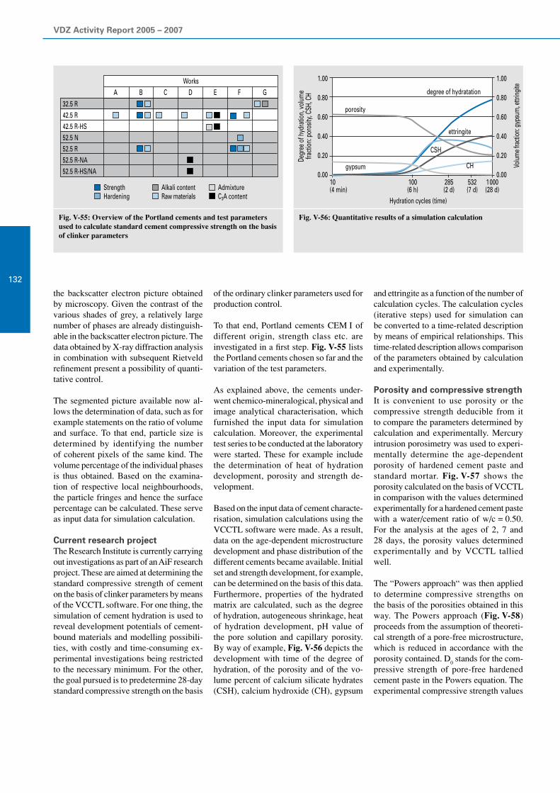
VDZ Activity Report 2005 – 2007
132
Fig. V-55: Overview of the Portland cements and test parameters used to calculate standard cement compressive strength on the basis of clinker parameters
Fig. V-56: Quantitative results of a simulation calculation
1.00
0.80
0.60
0.40
0.20
0.00
1.00
0.80
0.60
0.40
0.20
0.0010(4 min)
100(6 h)
285(2 d)
532(7 d)
1 000(28 d)
Hydration cycles (time)
gypsum
porosity
degree of hydratation
ettringite
CSH
Degr
ee o
f hyd
ratio
n, vo
lum
efra
ction
: por
osity
, CSH
, CH
Volum
e fra
ction
: gyp
sum
, ettr
ingite
CH
32.5R42.5R42.5R-HS52.5N52.5R52.5R-NA52.5R-HS/NA
StrengthHardening
AlkalicontentRawmaterials
AdmixtureC3Acontent
WorksA B C D E F G
the backscatter electron picture obtained by microscopy. Given the contrast of the various shades of grey, a relatively large number of phases are already distinguish-able in the backscatter electron picture. The data obtained by X-ray diffraction analysis in combination with subsequent Rietveld refinement present a possibility of quanti-tative control.
The segmented picture available now al-lows the determination of data, such as for example statements on the ratio of volume and surface. To that end, particle size is determined by identifying the number of coherent pixels of the same kind. The volume percentage of the individual phases is thus obtained. Based on the examina-tion of respective local neighbourhoods, the particle fringes and hence the surface percentage can be calculated. These serve as input data for simulation calculation.
Current research projectThe Research Institute is currently carrying out investigations as part of an AiF research project. These are aimed at determining the standard compressive strength of cement on the basis of clinker parameters by means of the VCCTL software. For one thing, the simulation of cement hydration is used to reveal development potentials of cement-bound materials and modelling possibili-ties, with costly and time-consuming ex-perimental investigations being restricted to the necessary minimum. For the other, the goal pursued is to predetermine 28-day standard compressive strength on the basis
of the ordinary clinker parameters used for production control.
To that end, Portland cements CEM I of different origin, strength class etc. are investigated in a first step. Fig. V-55 lists the Portland cements chosen so far and the variation of the test parameters.
As explained above, the cements under-went chemico-mineralogical, physical and image analytical characterisation, which furnished the input data for simulation calculation. Moreover, the experimental test series to be conducted at the laboratory were started. These for example include the determination of heat of hydration development, porosity and strength de-velopment.
Based on the input data of cement characte-risation, simulation calculations using the VCCTL software were made. As a result, data on the age-dependent microstructure development and phase distribution of the different cements became available. Initial set and strength development, for example, can be determined on the basis of this data. Furthermore, properties of the hydrated matrix are calculated, such as the degree of hydration, autogeneous shrinkage, heat of hydration development, pH value of the pore solution and capillary porosity. By way of example, Fig. V-56 depicts the development with time of the degree of hydration, of the porosity and of the vo-lume percent of calcium silicate hydrates (CSH), calcium hydroxide (CH), gypsum
and ettringite as a function of the number of calculation cycles. The calculation cycles (iterative steps) used for simulation can be converted to a time-related description by means of empirical relationships. This time-related description allows comparison of the parameters obtained by calculation and experimentally.
Porosity and compressive strengthIt is convenient to use porosity or the compressive strength deducible from it to compare the parameters determined by calculation and experimentally. Mercury intrusion porosimetry was used to experi- mentally determine the age-dependent porosity of hardened cement paste and standard mortar. Fig. V-57 shows the porosity calculated on the basis of VCCTL in comparison with the values determined experimentally for a hardened cement paste with a water/cement ratio of w/c = 0.50. For the analysis at the ages of 2, 7 and 28 days, the porosity values determined experimentally and by VCCTL tallied well.
The “Powers approach“ was then applied to determine compressive strengths on the basis of the porosities obtained in this way. The Powers approach (Fig. V-58) proceeds from the assumption of theoreti-cal strength of a pore-free microstructure, which is reduced in accordance with the porosity contained. D
0 stands for the com-
pressive strength of pore-free hardened cement paste in the Powers equation. The experimental compressive strength values

V Concrete constituents, concrete technology and concrete engineering
133
Fig. V-57: Age-dependent porosity of the hardened cement paste – comparison of experimental and simulation results
Fig. V-58: Compressive strength of hardened cement paste calculated by means of the Powers equation; a) with porosity values measured experimentally; b) with porosity values obtained by simulation in comparison to compressive strengths determined experimentally
Com
pres
sive s
treng
th in
N/m
m2
50
40
30
20
10
0
Powers, based on: experimental porosity(D0 = 133; k = 4)Powers, based on: simulated porosity(D0 = 195; k = 5.1)Measured values for hardened cement paste
D(t) = D0 · X(t)K = D0 · 1 + P(t) / F(t)1 K
( )
compressive strength of thehardened cement paste
compressive strength of thepore-free hardened cement paste
density ratio of the hydrationproducts
timeconstant solid
porosity
2 7 28Age in days
Poro
sity i
n %
50
40
30
20
10
0
experimentsimulation
2 7 28Age in days
CEM I 42.5 R; w/c = 0.5
were determined on standard mortar prisms having dimensions of 40 x 40 x 160 mm3 according to EN 196.
Fig. V-58 shows the compressive strength of a Portland cement CEM I 42.5 R with a water/cement ratio of w/c = 0.50 that was determined experimentally, listing it opposite the compressive strengths calcu-lated from the porosities using the Powers approach. Laboratory tests and calculation tallied well in this case, too.
The relationship between standard com-pressive strength and the strength of the hardened cement paste is influenced, among other factors, by the microstructure formation in the interfacial zone between the standard sand and the hardened cement paste. Further empirical models are check-ed to take standard sand into account in compressive strength calculation. Among others, models that take into consideration the dependence of the module of elasticity on porosity are to be reverted to. The way in which the impact of standard sand can be taken into account during VCCTL simu-lation forms part of the research project currently underway as well.
Standardisation
Following the adoption of the concrete standards EN 206-1 and DIN 1045 by the building supervisory authorities in August 2002 and the expiry of the transition peri-od on 31 December 2004, the new gener- ation of standards for concrete construction has now fully superseded the old one. The standards are applied under practical con-ditions. An A1 amendment served to bring DIN 1045-2 up to date in technical and formal respect by the end of the transition
period. This amendment of the standard became necessary to allow the following items to be taken into account:
Inclusion of the k-value concept for fly ash in combination with CEM II-M cements
Changes resulting from the new na-tional or European product standards for cement, concrete admixtures and aggregates
Incorporation of the corrigenda to DIN 1045-2
During the period under review, a further amendment to DIN 1045-2 was elaborated. The changes resulted from the experiences gained in applying EN 206-1 and DIN 1045-2, from the extrapolation of European and national product standards for concrete constituents and their application rules, as well as from new research results.
A2 amendment to concrete standard DIN 1045-2Based on the results of a research project carried out by the technical universities of Aachen and Munich, DIN 1045-2 was supplemented by amendment A2 permit-ting the use of the k-value concept for hard coal fly ash as a concrete addition in concrete exposed to freeze-thaw with de-icing salt (exposure classes XF2 and XF4) in early 2007. Furthermore, the applica-tion of cements containing fly ash in these and further exposure classes is no longer excluded. When Portland-fly ash cement CEM II/A-V or Portland-composite cement CEM II/A-M (P-V) was used in concrete for exposure class XF3, it was previously not admissible to offset fly ash used as concrete addition against the water/cement ratio and the minimum cement content. This
restriction was dropped, as were the restric-tions of use for CEM II/A-V in exposure classes XF2 and XF4 and of CEM II/B-V in exposure classes XF2, XF3 and XF4. Moreover, the use of CEM II/A-M (S-V, V-T, V-LL) and CEM II/B-M (S-V, V-T) in concrete according to EN 206-1 and DIN 1045-2 is no longer subject to any re-strictions. The exclusion from application for exposure class XF3 ceases to apply for cements CEM II/B-M (D-V) and CEM II/B-M (P-V). If fly ash is used as a main con-stituent in Portland-composite cements, the contents of fly ash can be higher as when used as a concrete addition since the optimi-sation of cement properties allows a perfor-mance level meeting practical demands to be set in the concrete. This is confirmed by investigations the Research Institute carried out as part of AiF-sponsored research pro-grammes. Given the previous restrictions of use for cements containing fly ash, the main focus was placed on tests regarding freeze-thaw and freeze-thaw with de-icing salt. Additionally, however, the carbonation behaviour of the concretes was analysed (cf. section on “Cements with several main constituents).
Ground granulated blastfurnace slag as a concrete addition Harmonised European standard EN 15167 covering ground granulated blastfurnace slag as a concrete addition appeared at the end of 2006. The standard was subdivided in two parts following the standards or draft standards, respectively, for the concrete additions fly ash and silica fume:
Part 1: Composition, requirements and conformity criteria
Part 2: Conformity evaluation

VDZ Activity Report 2005 – 2007
134
Country Cement type k-value Supplementaryexplanations
Austria CEM ICEM II
0.40.4
GGBS/(c + GGBS) ≤ 25GGBS/(c + GGBS) ≤ 20
Belgium CEM I 0.9 GGBS/(c + GGBS) ≤ 0.31GGBS/(c + GGBS) ≤ 0.17 for external components
Finland all 0.8 k = 1.0 for XA (chemical attack)
France CEM I 0.9 max. GGBS/(c + GGBS) = 0.30depending on ambient conditions
Norway CEM I , II, III depending on ambient conditions
0.6 Minimum cement content:(c + k · GGBS) > min. c
Sweden CEM I, CEM II 0.6 GGBS/(c + GGBS) ≤ 0.34
Table V-5: Use of ground granulated blastfurnace slag as a concrete addition including thek-value concept according to national application documents to the European concrete standard EN 206-1
In Germany, ground granulated blastfur-nace slag must not be applied in the domain subject to building inspectorate approval until corresponding regulations will have been adopted.
While the production and use of cements containing blastfurnace slag look back on a long and successful tradition in Germa-ny, ground granulated blastfurnace slag (GGBS) as a concrete addition is hardly utilised at all. In some European countries, such as Great Britain, GGBS is also used as a concrete addition in building con-struction and civil engineering. However, these experiences cannot be transferred to Germany without some qualification. The board of the German Committee for Structural Concrete (DAfStb) therefore de-cided not to establish any application rules for ground granulated blastfurnace slag in concrete for the time being. It recommends applying for technical approvals with the German Institute for Building Technology (DIBt). Application rules within the scope of the concrete standard can be established when experience from a sufficient number of approvals will be available.
Extensive experience with the application of cements containing blastfurnace slag that also extends to the durability of the concretes made from them is available in Germany. This scope of experience is left behind in the ambit of the European GGBS standard EN 15167-1 if the GGBS does not have to meet any further requirements. The standard for ground granulated blastfur-nace slag defines a performance level that is lower than the one that can be presupposed
in the production of cements containing blastfurnace slag in Germany. This relates to the fineness, the glass content and the strength contribution of GGBS. Moreover, experience with blastfurnace slags referred to as pelletised, i.e. which were air-cooled, is not available in Germany. Cement ma-nufacturers and blastfurnace slag suppliers cooperate closely today. Moreover, quality variations regarding the chemical and phy-sical properties of the blastfurnace slags are detected by the cement manufacturer’s autocontrol of blastfurnace slags and com-pensated by appropriate measures during cement manufacture. To do so, cement manufacturers can revert to the following measures in particular:
Adjustment of clinker and blastfurnace slag fineness (in intergrinding or sepa-rate grinding)
Optimisation of the mix formulation (raising or lowering the blastfurnace slag portion)
Control of the quantity and composition of the sulphate agent
It took German cement manufacturers many decades of practical experience to acquire their know-how on the carefully directed adjustment of the properties of ce-ments containing blastfurnace slag. Given the present lack of experience, one cannot say which of the control variables could be transferred to the application of GGBS as a concrete addition in concrete production under practical conditions in Germany. It is further uncertain whether a level of flexibility and safety comparable to that achieved in the use of cements containing blastfurnace slag could be attained.
Basically, two concepts are eligible as an application rule for GGBS as a concrete addition:
k-value concept Equivalent concrete performance
The k-value concept is applied for GGBS used as a concrete addition in Sweden and France, for example (Table V-5). In Germany, the suitability of the k-value concept is considered proven only for fly ash and silica fume so far. According to DIN 1045-2, Annex E, the principle of equivalent concrete performance can only be applied under the terms of national technical approvals in Germany. These approval procedures have not been imple-mented to date. Approvals for concretes deviating from DIN 1045-2 are granted in numerous cases (e.g. for mass concrete); the same applies to technical approvals for Portland-composite cements. The approval of standardised cements for use in certain exposure classes required an extensive trial programme including tests on carbonation behaviour, on resistance to chloride pene-tration, on resistance to freeze-thaw and on resistance to freeze-thaw with de-icing salt. The results of the qualification tests were evaluated by the competent Expert Committee (SVA) of the DIBt. If applic-able, requirements exceeding those of the standard were specified in the approvals. A comparable way of proceeding is to be expected for national technical approvals according to Annex E of DIN 1045-2. It is not possible to formulate an application rule solely based on strength verification without securing the durability properties of concretes accordingly.
The VDZ elaborated a state-of-the-art report in cooperation with the ready-mixed concrete industry and the Ironworks Slag Research Association. The Building Materials and Materials Testing centre of Munich technical university (Prof. Heinz) and the Institute for Building Research of RWTH Aachen (Prof. Brameshuber) were involved in this project as well. Besides documenting the experiences with ground granulated blastfurnace slag used as a concrete addition, the report also highlights the need for research as well as concepts for applications. The report will appear in the series of publications issued by the German Committee for Structural Concrete (DAfStb) in the course of 2007.

V Concrete constituents, concrete technology and concrete engineering
135
Countrymax.
(w/c)eq
min. c
kg/m3
CEM I
CEM IICEM III CEM IV CEM V
S LL M
A B A B A B A B A B A B
Austria 0.55 300 x x x (x) x (x)
Belgium 0.55 300 x x x x x x x x x (x)
Denmark 0.55 150 (x) (x)
Finland 0.60 270 x x x x x x x
Germany 0.60 280 x x x x (x) (x) x x (x) (x) (x)
Ireland 0.60 300 x
Italy 0.50 320 x x x x x x x x x x x x x
Netherlands 0.55 300 x x x (x) (x) (x) (x) x x (x) (x) (x) (x)
Norway 0.60 250 x x x
Great Britain 0.60 280 x x x x x x (x) (x)
x permitted not mentioned
(x) with restrictions not permitted
Table V-6: Comparison of the application rules for cement laid down in national application documents to European concrete standard EN 206-1 based on the example of a concrete for external components
Future development of European concrete standardisationAccording to the CEN regulations, a CEN standard has to be routinely reviewed every five years. The European concrete standard EN 206-1 would have had to undergo this review in the year 2005. However, since application of the standard had only just started in many member countries and had not yet started in some others at all, only little experience with the standard had been gained. CEN/TC 104 “Concrete and related products” therefore did not consider a revi-sion to be reasonable before the year 2010. This view was confirmed by correspond-ing resolutions during the CEN meetings held in Larnaca in November 2005. The members were recommended to respond accordingly in corresponding enquiries conducted by the CEN. According to the CEN regulations, it is not possible to carry out any further amendments of EN 206-1 without publishing a new issue as it already comprises two amendments. CEN/TC 104 proceeds from the assumption that, in its current form and taking into account the two amendments already implemented, EN 206-1 no longer has any major defi-ciencies.
In the period under review a task force of CEN/TC 104/SC1 “Concrete” elabora-ted a synopsis of the national application documents (NAD) to European concrete standard EN 206-1. The synopsis highlight-ed that further harmonisation, especially with regard to specifications relevant to durability, is virtually impossible. The summaries make evident, for example, that
internal components are not subject to any restrictions regarding either the maximum w/c ratio or the minimum cement content in some countries. Although the vast ma-jority of NAD specifies values, their levels vary widely in some cases. Many countries call for minimum compressive strength of concrete, while five countries have not spe-cified any requirements at all. The exposure class most frequently defined for interior components is XC1, while some countries assigned classes X0 or XC3, respectively. A combination of exposure classes XC4 and XF1 is assigned to external components in several countries. Specifications for mini-mum compressive strength either range between C25/30 and C32/40 or do not exist. A maximum w/c ratio of 0.60 to 0.50 is indicated. The minimum cement content ranges between 150 and 320 kg/m3. The discrepancies regarding cement application are considerable in some cases as well. In addition to the traditional differences in market conditions and construction prac-tice, this also reflects the philosophies under- lying the imposition of rules (Table V-6). While the German application standard DIN 1045-2 lays down specifications for the application of all 27 basic cement types and for a number of CEM II-M cements additionally, other NAD only regulate the application of few cement types that have traditionally played a role in the respective national market.
In preparation of a further revision of EN 206-1 different task groups will work out proposals on the following topics:
Self-compacting concrete Equivalent Performance Concept Use of additions Conformity evaluation
Water-impermeable concrete struc- tures: WU guidelines of the DAfStbThe use of water-impermeable concrete has been regulated by guidelines of the German Committee for Structural Concrete (DAfStb) since late 2003. These closed a gap in the regulations on the water-proofing of buildings according to DIN 18195 that often turned out to be a competitive dis-advantage for concrete construction. The comments on the guidelines appeared as volume 555 of the DAfStb by now. These comments serve to explain the background of the regulations to users and to supply further detailed information.
Water-impermeable (WU) construction with concrete (Fig. V-59) proved itself as a robust and durable construction, meeting even demanding service require-ments in the past. When WU concrete constructions are to be applied in case of higher demands being placed on the use of rooms, an issue that is often contro-versial is the quantity of moisture releas-ed and the moisture transport through the structural elements. The DAfStb drew up a corresponding position paper reflecting the state of the art (published in beton 56 (2006), vol. 10, p. 470-471). This position paper clearly points out again that the “specifications of the WU guide-lines were designed to ensure that only the
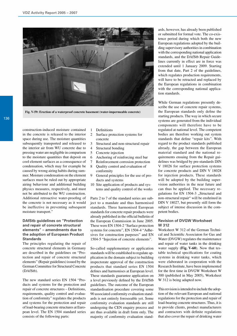
VDZ Activity Report 2005 – 2007
136
Fig. V-59: Erection of a waterproof concrete basement (water-impermeable concrete)
construction-induced moisture contained in the concrete is released to the interior space during use. The moisture quantities subsequently transported and released to the interior air from WU concrete due to pressing water are negligible in comparison to the moisture quantities that deposit on cool element surfaces as a consequence of condensation, which may for example be caused by wrong airing habits during sum-mer. Moisture condensation on the element surfaces must be ruled out by appropriate airing behaviour and additional building physics measures, respectively, and must not be attributed to the WU construction. Additional retroactive water-proofing of the concrete is not necessary as it would be ineffective in preventing subsequent moisture transport.”
DAfStb guidelines on “Protection and repair of concrete structural elements” – amendments due to the adoption of European Product StandardsThe principles regulating the repair of concrete structural elements in Germany are described in the guidelines on “Pro-tection and repair of concrete structural elements” (Repair guidelines) issued by the German Committee for Structural Concrete (DAfStb).
The new standard series EN 1504 “Pro-ducts and systems for the protection and repair of concrete structures – Definitions, requirements, quality control and evalua-tion of conformity” regulates the products and systems for the protection and repair of load-bearing concrete structures at Euro-pean level. The EN 1504 standard series consists of the following parts:
1 Definitions2 Surface protection systems for
concrete 3 Structural and non-structural repair4 Structural bonding5 Concrete injection6 Anchoring of reinforcing steel bar7 Reinforcement corrosion protection8 Quality control and evaluation of
conformity9 General principles for the use of pro-
ducts and systems10 Site application of products and sys-
tems and quality control of the works
Parts 2 to 7 of the standard series are sub-ject to a mandate and thus harmonised standards. Three harmonised European standards for concrete repair products were already published in the official bulletin of the European Commission in June 2005. These were EN 1504-2 “Surface protection systems for concrete”, EN 1504-4 “Adhe-sives for construction purposes” and EN 1504-5 “Injection of concrete elements”.
So-called supplementary or application standards will be established to regulate ap-plication in the domain subject to building inspectorate approval of the construction products that standard series EN 1504 defines and harmonises at European level. These standards guarantee application on a level previously defined by the DAfStb guidelines. The outcome of the European standardisation procedure covering some 90 associated conformity evaluation stand-ards is not entirely foreseeable yet. Some conformity evaluation standards are still undergoing the CEN enquiry process and are thus available in draft form only. The majority of conformity evaluation stand-
ards, however, has already been published or submitted for formal vote. The co-exis-tence period during which both the new European regulations adopted by the buil-ding supervisory authorities in combination with the corresponding national application standards, and the DAfStb Repair Guide-lines currently in effect are in force was extended until 1 January 2009. Starting from that date, Part 2 of the guidelines, which regulates production requirements, will have to be retracted and replaced by the European regulations in combination with the corresponding national applica-tion standards.
While German regulations presently de-scribe the use of concrete repair systems, the European standards only define the starting products. The way in which secure systems are generated from the individual components will therefore have to be regulated at national level. The competent bodies are therefore working out system standards that define “repair kits”. With regard to the product standards published already, the gap between the European material standard and the national re-quirements ensuing from the Repair gui-delines was bridged by pre-standards DIN V 18026 for surface protection systems for concrete products and DIN V 18028 for injection products. These standards will be adopted by the building super- vision authorities in the near future and can thus be applied. The necessary re-gulations for EN 1504-3 „Structural and non-structural repair“ will be enshrined in DIN V 18027, but presently still form the subject of intense discussion in the com-petent bodies.
Revision of DVGW Worksheet W 312Worksheet W 312 of the German Techni-cal and Scientific Associaton for Gas and Water (DVGW) regulates the maintenance and repair of water tanks in the drinking water supply (Fig. V-60). Now that tes-table technical specifications for coating systems in drinking water tanks, which were elaborated in cooperation with the Research Institute, have been implemented for the first time in DVGW Worksheet W 300 (published in May 2005), Worksheet W 312 is being adapted now.
This revision is intended to include the adop-tion of the relevant European and national regulations for the protection and repair of load-bearing concrete structures. Thus, it is to provide clients, product manufacturers and contractors with definite regulations that also cover the repair of drinking water

V Concrete constituents, concrete technology and concrete engineering
137Fig. V-60: Drinking water tank after repair
Fig. V-61: Laying of concrete pipes for the effluent domain
tanks. As a consequence, manufacturers will have to carry out adequate identity tests on the respective substances – similar to those already conducted for products utilised in accordance with the DAfStb Repair Guidelines. In the case of new prod-ucts, new mix formulations or significant changes in composition or raw materials, the initial tests (basic tests) specified have to be carried out. Manufacturers subse-quently declare conformity on the basis of initial testing of the construction product and factory production control (FPC).
Revision of ATV-M 168 and standardisation in the field of concrete pipesWith its Advisory leaflet ATV-M 168 “Cor-rosion of Wastewater Systems – Waste- water Discharge” published in 1998, the Wastewater Management Association (ATV) presented technical regulations on the topic of corrosion in effluent disposal plants for the first time. Adjustment to new developments regarding technology and standards, such as the new concrete standards EN 206-1 and DIN 1045-2, is effected in the current revision of the datasheet, which is implemented by ATV-DVWK’s successor association, the Ger-man Association for Water, Wastewater and Waste (DWA) located in Hennef. While the requirements for concrete in contact with the soil or the ground water is regulated in exposure classes XA according to EN 206-1 and DIN 1045-2, the present datasheet specifies limit values for permanent, tem-porary or short-term exposure of concrete to municipal sewage and waste water (ex-posure class “inside of pipe”).
Moreover, regulations defining the speci-fications for piping concrete (Fig. V-61) are included in the European regulation EN 1916 (water/cement ratio ≤ 0.45) and in the national supporting standards DIN V 1201 (strength class type 1 C35/45 and type 2 C40/50; minimum cement content corresponding to XA1 for type 1 and cor-responding to XA2 for type 2 in confor-mity with EN 206-1/DIN 1045-2). Assign-ing the piping concretes for the “inside of pipe” application case to exposure classes XA1 and XA2, which are only applicable for the soil and the ground water accor-ding to EN 206-1/DIN 1045-2, does not represent a satisfactory solution as it will result in controversial discussions both at national and European level.
Two alternatives for securing the durabil-ity of concrete pipes are currently being discussed at European level:
Defined requirements for concrete (maximum water/cement ratio, strength class, minimum cement content, etc.); no harmonised European solution re-garding concrete specifications – except for the water/cement ratio – was found during the elaboration of EN 1916
Performance testing on piping con-crete; however, neither defined test methods nor corresponding limit values are presently available
Given this scenario, the task to be perform-ed by TG2 of CEN TC 165 WG 9 is to work out a feasibility study presenting a European solution to ensure the durability of concrete pipes. If, as before, an agree-ment on defined specifications for concrete cannot be reached, attention may possibly focus on performance tests.

VDZ Activity Report 2005 – 2007
138
Fig. V-62: Analysis of the structural state of a drinking water tank
Consultancy and expert’s advisory services
The demand for concrete technology con-sultancy and expert’s advisory services rendered by the Research Institute of the Cement Industry has increased consider-ably over the past years. This principally applies to the following key areas:
Development of optimised concrete and mortar mixes custom-made for the respective clients’ area of application
Execution of structure analyses (e.g. on drinking water tanks, Fig. V-62) and evaluation
Establishment of repair concepts Questions regarding alkali-silica reac-
tion and the evaluation of aggregates (cf. section on alkali-silica reaction)
Chemical attacks on concrete
The provision of efficient solutions to some- times complex problems is ensured by specialists covering all aspects of concrete technology who are represented on the corresponding national and international panels and boast extensive experiences gathered in laboratories and under practi-cal conditions. The multidisciplinary co-operation with experts from the fields of mineralogy, chemistry, physics and pro-cess technology employed in the Research Institute’s other departments is of particular advantage in this context.
Two projects from the field of optimised concrete and mortar mix development for
which the Research Institute’s support was enlisted will be presented below. Their ample experience gained from research activities and from the developments on self-compacting concrete in particular en-abled the specialists to propose efficient solutions for the specific problems. The projects involved the erection of an under-ground high-pressure dam and filling up a high-temperature pilot reactor with light-weight aerated concrete.
“High-pressure dam” projectIn conjunction with the planned central drainage for the decommissioned mining territories in Emscherlippe, Haard and Blumenthal, the cross measure drift to the Haltern and Auguste-Victoria panels was partitioned by a high-pressure dam on the third stratum. The high-pressure dam has to ensure water-impermeable barrage while absorbing a maximum possible hydrostatic pressure of 55 bar. The particular challenge this involved was the first-ever convey-ance of construction concrete via a DN 80 pipe of 2.6 km length to the underground spreading site. The concrete thus had to be hydraulically conveyable and permit con-tinuous pouring at a transporting capacity of up to 30 m3/h. The further requirements it had to meet were stability to sedimenta-tion, low shrinkage, self-compaction and water-impermeability. The suitability of this special concrete was verified by the Research Institute, the company Wiemer & Trachte, Dortmund, was in charge of building execution, and the special con-crete was supplied by the company Elskes, Duisburg.
“Reactor fill-up” projectThe Pilot Reactor AVR GmbH group of construction firms in Jülich operated a helium-cooled graphite-moderated high-temperature reactor (HTR) with an output of 15 MW from 1967 till its scheduled shutdown in 1988. In compliance with the permits granted pursuant to the Atomic Energy Law, work associated with de-commissioning, the unloading of fuel from the reactor core, the dismantling of plant sections and the installation of a material lock has been performed since 1994. One of the measures that AVR has planned to fully dismantle the plant consists of filling up the reactor vessel with light-weight aer-ated concrete having a density of approx. 0.7 kg/dm3 in order to fix the equipment built into the reactor vessel for dismount-ing. The reactor vessel filled up with light weight aerated concrete is to be removed from the reactor building without being dis-mantled and then be transported to an inte-rim storage facility located on the premises of the Jülich research centre by means of an air cushion transport system. This is where the reactor vessel is to be intermediately stored till its conditioning is appropriate for final storage. Concrete technology development of the light weight aerated concrete was implemented in cooperation with the company Schlumberger Oilfield Services, Vechta. The light weight aerated concrete had to be characterised by low raw density as well as adequate compres-sive strength and compressibility. To make sure it could be filled up reliably, it further had to possess sufficient pumpability, good flowability and high mix stability.
Besides providing concrete technology consultancy and expert’s advisory services, the Research Institute can also carry out virtually all concrete technology investiga-tions and tests under the terms of contract investigations. Customary standardised testing is accredited according to EN ISO 17025. In order to be braced for any future questions arising, the pool of testing equip-ment is continually extended. In the period under review, for example, the device for porosity determination by mercury intru-sion measurement was supplemented by a further high-pressure component (Pascal 440). As a consequence, the pore range that can be reproduced was extended to include finer pores (up to 1.8 nm) due to higher compression stressing of up to 400 MPa. The capacities of testing for possible alkali-silica reaction were extended to a total of four testing cabinets for carrying out the 60 °C concrete test (cf. section on alkali-silica reaction).

V Concrete constituents, concrete technology and concrete engineering
139

VDZ Activity Report 2005 – 2007
140 Environmental compatibility of cement and concrete
VI
Extraction of cement raw materials in a quarry
Cement is the most important binder for the building materials sector; it is produced in large quantities worldwide. Accordingly, the environmentally compatible manufacture and application of cement is of utmost importance. The German cement industry has in-tensely investigated the environmental compatibility of cement-based building materials throughout their life cycle for many years. Initially, the main focus was placed on the environmentally compatible manufacture of cement. In conjunction with the increasing utilisation of alternative materials in cement production, attention has increasingly focused on the product cement.
For alternative materials to be utilised in the German cement industry, it is indispensable that they neither cause environmental impacts during cement manufacture nor impair the structural and environmentally relevant properties of the cement or concrete, respectively. Extensive investigations carried out by the Research Institute corroborate that the influence of a cement works on the ambient pollution level prevailing at the site is only very slight. Furthermore, alternative material use does not significantly change trace element contents in the cement, which range within the same order of magnitude as the contents of natural rocks, soils, or clays. All leaching tests performed to date have further showed that the quantities of trace elements released from cement-based building materials are only very small and do not have any adverse effect on the environment.
The European Construction Products Directive in particular lays down specifications regarding hygiene, health and environmental protection with which building materials have to comply. Cement and concrete have proved their excellent suitability for structural elements that have been in contact with soil, ground and surface water as well as drinking water for many decades. For that reason, the applicable technical regulations do not provide for any additional attestations regarding hygiene or environmental compatibility for standard cements and construction products made from them. In Germany, such attestations are currently only required to obtain building inspectorate approval for new, unknown construction products and for materials in contact with drinking water. It is uncer-tain whether the corresponding European regulations currently being elaborated will change this. The Research Institute is represent-ed on the competent panels and does its utmost to ensure that standardised cements can continue to be used in the manufacture of construction products and structural elements in contact with the soil as well as surface and ground water without testing. In doing so, the Institute can revert to many years of extensive experiences with cement and concrete as well as numerous research results.
Public awareness of the impact that construction has on the regional and global environment and thus on the natural foundations of life has been growing continually. As a consequence, ecological aspects increasingly influence the choice of the building materials and types of construction to be used today. The ideal of sustainable development is done justice in the field of construction when structures tailored to the users’ needs are erected at low cost and with low environmental impact and used durably. The German Committee for Structural Concrete will draft a corresponding document of general principle in the medium term which will pro- vide evaluation rules and technical recommendations on sustainable building with concrete to the parties involved. The Research Institute is intensely involved in the elaboration of this paper, which further is to serve to incorporate the ways of proceeding established in Germany into future European standards and directives.

VI Environmental compatibility of cement and concrete
141

VDZ Activity Report 2005 – 2007
142
Environmental criteria for cement-based building materials
The clinker burning process is a material conversion process that is characterised by the strong alkaline reaction of the kiln feed, high kiln feed temperatures of approx. 1 450 °C, and intensive contact between the solids and the kiln gas, which reaches gas temperatures of up to 2 000 °C. Thus, the rotary kilns of the cement industry present excellent conditions for the reliable and environmentally compatible utilisation of many residuals. However, on principle the German cement industry only uses residuals that do not have any adverse ef-fect on emissions, the homogeneity and the structural properties of the cement as well as its environmental compatibility. Extensive investigations carried out by the Research Institute corroborate that the utilisation of alternative materials com-mon in the German cement industry today does not significantly change trace element contents in the product. Overall, the trace element contents of German cements range within the same order of magnitude as the contents of natural rocks, soils, or clays. This applies regardless of whether or not alternative materials are used in cement manufacture.
Alternative material useGiven its process-specific conditions, the clinker burning process is very well suited for recovering the thermal and material content of numerous alternative materials. Depending on the raw material situation of a cement works, secondary by-products can be utilised as raw material constituents or as corrective materials for the raw mix, respectively. The materials used include industrial lime, used foundry sand, roasted pyrite, fly ash as well as residuals from the iron and steel industries etc. Table VI-1 summarises the alternative raw materials utilised in 2005.
Alternative fuels can be substituted for primary fuels in an environmentally com-patible fashion. In the year 2006, approx. 50% of the fuel energy consumption of the German cement industry was covered by alternative fuels. Most prominent among those were processed fractions from com-mercial and industrial waste, used tyres, waste oil, meat and bone meal, animal fat and scrap wood. In the years from 2000 to 2006, the alternative fuel use in the German cement industry grew from 25.7% to 49.9% (Fig. VI-1). Energy recovery contributes to CO
2 reduction without generating produc-
Group Alternative raw materialUse in
1 000 t/a
Ca
Lime sludge from drinking water and sewage treatmentLime hydrateFoam concrete granulatesCalcium fluoride
94
Si Used foundry sand 149
Si-Al Residues from coal pre-treatment 3
Fe
Roasted pyriteContaminated oreIron oxide/fly ash blendsDusts from steel plantsMill scale
137
Si-Al-Ca
Granulated blastfurnace slag 51
Fly ash 381
Paper residuesAshes from incineration processesMineral residuals, e.g. soil contaminated by oil
107
S Gypsum from flue gas desulphurisation and other gypsum 27
Al Residues from salt slag reprocessing, aluminium hydroxide 57
Table VI-1: Utilisation of alternative raw materials in clinker production (year 2006)
tion-specific residuals. The high tempera-tures in the rotary kiln firing unit ensure that organic substances are virtually fully converted to carbon dioxide and water. The emission concentrations of organic compounds, such as dioxins, furans etc., are therefore very low. This is true again regardless of the fuels utilised.
Trace elements in the cementLike all building materials deriving from natural raw materials, cement contains small quantities of trace elements. The trace element content in the clinker is substantially influenced by the trace el-
Fig. VI-1: Development of alternative fuel utilisation in the German cement industry
ement contents of the raw materials used in clinker production. These contents may differ considerably depending on the raw material deposit. The behaviour of the trace elements during the clinker burning process is determined by their physical/chemical properties, most particularly by their volatility. Depending on their vapour pressure, the trace elements input with the fuels and raw materials can evaporate fully or in part in the hot zones of the preheater and/or the kiln and react with the other constituents present in the gas phase. In the cooler sections of the kiln systems, they may condense on the kiln feed.
60
50
40
30
20
10
0
30.334.9
42.2
48.8
Alte
rnat
ive fu
el pr
opor
tion
in %
2000 2001 2002 2003 2004 2005
38.3
25.7
49.9
2006

VI Environmental compatibility of cement and concrete
143
Non-volatile elements, such as arsenic, beryllium, chromium, copper, nickel, vanadium and zinc, as well as not eas-ily volatilised elements, such as lead and cadmium, are discharged from the kiln sys-tem with the clinker virtually completely. The easily volatilised element thallium is retained in the preheater, which results in an internal recirculating system being formed. The highly volatile element mercury can condense on the dust particles at temperatures below approx. 120 °C in the exhaust purification units and be separated with them.
Depending on the chemical properties of the elements and the process conditions, the fixation of the trace elements in the clinker phases may occur in different ways. For example, barium replaces calcium in nearly all clinker phases. Chromium is sub-stantially combined in C
2S. Manganese is
combined in C4AF and can replace silicon
and calcium in C3S. Zinc is fixed in C
3S
and C2S and improves clinker phase for-
mation. Other elements, such as arsenic and antimony, form not easily volatilised compounds such as calcium arsenate or calcium antimonite. As a consequence of this fixation of the trace elements in the clinker phases, these trace elements do not dissolve spontaneously upon contact with water, but are only decomposed as hydra-tion progresses.
When suitable alternative fuels and/or raw materials are substituted for natural feed materials, their trace element content is an important assessment criterion. Given the utilisation of alternative materials common in the German cement industry today, the trace element content in the cements may both decrease and increase slightly. These changes are, however, usually superim-posed by the natural variations in the con-centrations of primary feed materials.
Trace element releaseCement, aggregates and, if necessary, con-crete additions and concrete admixtures are mixed with the mixing water to manufac-ture mortar and concrete. Just like cement, aggregates and concrete additions contain small quantities of trace elements, too. Experience shows that the trace element portion input into the building material together with the mixing water or the con-crete admixtures is negligible. It is, how-ever, not the content of potentially harmful substances that is decisive in assessing the environmental compatibility of a building material, but only the portion that can be released to the environmental media water,
soil or air during production, use, and pos-sibly also during dismantling or reuse.
Cement undergoes a series of complex chemical reactions immediately upon its first contact with the mixing water. Dur-ing these reactions, calcium sulphate and a small proportion of the tricalcium alu-minate, for example, are dissolved. The first reaction products thus generated are calcium hydroxide and trisulphate (et-tringite). After a few minutes, a hydroxyl ion concentration ranging between 50 and 80 mmol/l is reached. This corresponds to a pH value of 12.7 to 12.9. As a result of this high alkalinity, numerous metal ions, such as cadmium, mercury, manganese, cobalt and nickel, which might possibly be dis-solved once the cement gets in contact with the mixing water, are immediately precipi-tated again as insoluble hydroxides. Trace elements, such as arsenic or molybdenum, which form oxyanions, are precipitated as insoluble calcium compounds. Other trace elements are adsorbed on the cement phases formed or incorporated in their crystal lattice as hydration progresses further.
Given this chemical combination, the degree of release is determined by the proportion of a trace element that is dis-solved in the pore water of the hardened cement paste. In addition to the chemical interactions of the trace elements and the hydration products, a solid, largely water-impermeable structure is formed when cement-based building materials harden. For that reason, substances dissolved in the pore water can only leach from the hard-ened concrete by diffusion processes taking place in the liquid-filled pores of the mortar or concrete. The driving force behind dif-fusion is the difference in the concentra-tions of the respective substances in the pore solution and in the leaching ambient water. The transport rate is substantially determined by the diffusion behaviour of the respective substance and the pore distribution of the cement-based building material, most particularly by the propor-tion of interconnected capillary pores. In expertly made concretes, the diffusion rate of a substance can be reduced by a factor of up to 5 000 in comparison to free diffu-sion in water.
The excellent properties of cements in binding trace elements formed the subject of many research activities. All the leaching tests performed to date showed that only very small quantities of trace elements are released from cement-based building mate-rials. The bottom line is that cement-based
building materials do not have any adverse effects on the environment under common application conditions.
In order to gain a more profound insight into the fixation and release of trace ele-ments in/from cement-based building materials, a European consortium started the “Environmental Criteria for Cement Based Products (ECRICEM)” research project as early as several years ago. The partners involved in this research are the Energy Research Centre for the Nether-lands, Holcim Group Support Ltd, Ciments d’Obourg, Norcem A.S. and the Verein Deutscher Zementwerke. The main focus of the research work was initially placed on investigating the extent to which trace ele-ments can be released from cement-based building materials. To that end, Portland cements and cements with several main constituents from production sites through-out the world were used. The cements chosen had high trace element contents by nature. The investigation results sub-stantiated the environmentally favourable performance of cement-based building materials. They further showed that all cements generally possess the same kind of release characteristics.
Upon conclusion of the experimental work in the year 2004, intense efforts were ex-pended on modelling the chemical reac-tions in cement-based building materials. Understanding of the “controlling” factors which determine the solubility of a trace element in the pore water and thus its diffusion-controlled release is indispen-sable for evaluating the long-term leach-ing behaviour of cement-based building materials. Thus, a certain trace element cannot be regarded in isolation, but only with regard to its interaction with other constituents in the pore water and with the cement hydrate phases. Model calculations constitute the only way of taking into ac-count these interactions, for example the formation of hardly soluble compounds such as lead chromate, which can have a decisive impact on the release of the cor-responding elements.
The simulation by laboratory experiments of other effects, such as carbonation or the formation of protective carbonate layers, which have an effect on the release of trace elements from concretes in contact with surface water, ground water and the soil, is difficult as well. In this case, mechanistic model calculations can be applied to esti-mate the impact these effects have on the leaching of trace elements. The so-called

VDZ Activity Report 2005 – 2007
144
“source term” for leaching can be deter-mined by means of experimental results, for example leaching tests in a long-term tank leaching test (Fig. VI-2) , and corre-sponding model calculations.
Furthermore, calculation models on the diffusion of substances in the soil and the ground water (transport model) were elaborated in the period under review. By combining the source term model and the transport model, laboratory results can be evaluated with regard to the environmental effect that a structure or structural element has on the vicinity of the structure under defined release scenarios. Thus, the con-centration curve of the trace elements can be calculated for any given distance from the structure – both for the unsaturated soil zone and for the ground water. Fig. VI-3 illustrates how trace elements from particu-late material used in road construction, for example, are released to the adjacent soil. The following seven release scenarios are being worked on intensely at present:
Particulate material in contact with the soil
Building rubble in contact with the soil
Monolithic material in contact with the soil
Monolithic material in contact with rain
Monolithic material in contact with drinking water
Fig. VI-2: Leaching of a concrete cube (dimensions:10 x 10 x 10 cm3) in a long-term tank leaching test
Monolithic material in contact with surface water
Roof surfaces in contact with rain
Overall it can be stated that the results of the ECRICEM project afford a solid, sci-entifically founded basis for the scheduled European standardisation work aimed at enshrining the substantial hygiene, health and environmental requirements in harmo-nised European product standards.
REACH
European and German regulationsThe significant rise in the environmental awareness of the general public is also reflected in regulations and standards. The environmentally relevant requirements for building materials in contact with the soil and the ground water or for the hygienic suitability of materials in contact with drinking water, for example, are speci-fied nationally. Moreover, corresponding European regulations are being worked on intensely at present. The specifications of the European Construction Products Directive are of particular relevance for cement-based building materials. The future REACH regulation will reform European legislation on chemicals. This will affect cements and cementitious preparations as well as other inorganic building materials and all chemicals.
Fig. VI-3: Release scenario for particulate material in contact with the soil (example: road construction)
REACHIn December 2006, the European Parlia-ment and the European Council adopted “REACH”, the new European regula-tion on the Registration, Evaluation and Authorisation of Chemicals. One of the most comprehensive European legislation processes thus came to its preliminary conclusion. A little less than six years after the publication of the first EU white book, and a good three years after the EU Commission elaborated the draft regula-tion and more than 4 600 applications for amendments were filed, the regulation now forms the preliminary basic framework of the new EU legislation on chemicals. Its actual implementation and thus also the viability and the cost-effectiveness of the regulations will eventually be determined by the various technical guidelines that the EU Commission is currently working out with the assistance of many experts. The ten different “implementation aids” intended for companies alone already comprise several thousand pages at present. For REACH to work in the end, especially small and medium-sized enterprises need simple instruments and aids. These are in turn being worked out by national institu-tions and associations.
Ground water
Soil
Point of evaluation
Source term
Material
Possible surfacing, e.g. road paving
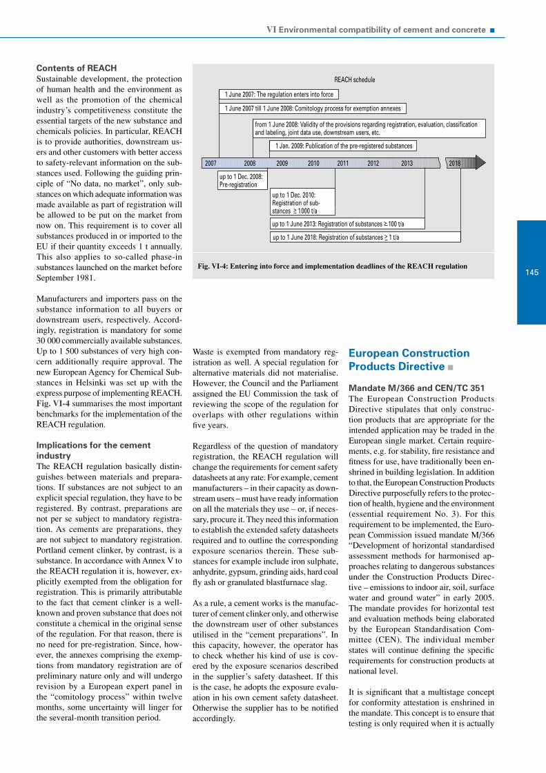
VI Environmental compatibility of cement and concrete
145
Contents of REACHSustainable development, the protection of human health and the environment as well as the promotion of the chemical industry’s competitiveness constitute the essential targets of the new substance and chemicals policies. In particular, REACH is to provide authorities, downstream us-ers and other customers with better access to safety-relevant information on the sub-stances used. Following the guiding prin-ciple of “No data, no market”, only sub-stances on which adequate information was made available as part of registration will be allowed to be put on the market from now on. This requirement is to cover all substances produced in or imported to the EU if their quantity exceeds 1 t annually. This also applies to so-called phase-in substances launched on the market before September 1981.
Manufacturers and importers pass on the substance information to all buyers or downstream users, respectively. Accord-ingly, registration is mandatory for some 30 000 commercially available substances. Up to 1 500 substances of very high con-cern additionally require approval. The new European Agency for Chemical Sub-stances in Helsinki was set up with the express purpose of implementing REACH. Fig. VI-4 summarises the most important benchmarks for the implementation of the REACH regulation.
Implications for the cement industryThe REACH regulation basically distin-guishes between materials and prepara-tions. If substances are not subject to an explicit special regulation, they have to be registered. By contrast, preparations are not per se subject to mandatory registra-tion. As cements are preparations, they are not subject to mandatory registration. Portland cement clinker, by contrast, is a substance. In accordance with Annex V to the REACH regulation it is, however, ex-plicitly exempted from the obligation for registration. This is primarily attributable to the fact that cement clinker is a well-known and proven substance that does not constitute a chemical in the original sense of the regulation. For that reason, there is no need for pre-registration. Since, how-ever, the annexes comprising the exemp-tions from mandatory registration are of preliminary nature only and will undergo revision by a European expert panel in the “comitology process” within twelve months, some uncertainty will linger for the several-month transition period.
Fig. VI-4: Entering into force and implementation deadlines of the REACH regulation
Waste is exempted from mandatory reg-istration as well. A special regulation for alternative materials did not materialise. However, the Council and the Parliament assigned the EU Commission the task of reviewing the scope of the regulation for overlaps with other regulations within five years.
Regardless of the question of mandatory registration, the REACH regulation will change the requirements for cement safety datasheets at any rate. For example, cement manufacturers – in their capacity as down-stream users – must have ready information on all the materials they use – or, if neces-sary, procure it. They need this information to establish the extended safety datasheets required and to outline the corresponding exposure scenarios therein. These sub-stances for example include iron sulphate, anhydrite, gypsum, grinding aids, hard coal fly ash or granulated blastfurnace slag.
As a rule, a cement works is the manufac-turer of cement clinker only, and otherwise the downstream user of other substances utilised in the “cement preparations”. In this capacity, however, the operator has to check whether his kind of use is cov-ered by the exposure scenarios described in the supplier’s safety datasheet. If this is the case, he adopts the exposure evalu-ation in his own cement safety datasheet. Otherwise the supplier has to be notified accordingly.
European ConstructionProducts Directive
Mandate M/366 and CEN/TC 351The European Construction Products Directive stipulates that only construc-tion products that are appropriate for the intended application may be traded in the European single market. Certain require-ments, e.g. for stability, fire resistance and fitness for use, have traditionally been en-shrined in building legislation. In addition to that, the European Construction Products Directive purposefully refers to the protec-tion of health, hygiene and the environment (essential requirement No. 3). For this requirement to be implemented, the Euro-pean Commission issued mandate M/366 “Development of horizontal standardised assessment methods for harmonised ap-proaches relating to dangerous substances under the Construction Products Direc-tive – emissions to indoor air, soil, surface water and ground water” in early 2005. The mandate provides for horizontal test and evaluation methods being elaborated by the European Standardisation Com-mittee (CEN). The individual member states will continue defining the specific requirements for construction products at national level.
It is significant that a multistage concept for conformity attestation is enshrined in the mandate. This concept is to ensure that testing is only required when it is actually
1 June 2007: The regulation enters into force
from 1 June 2008: Validity of the provisions regarding registration, evaluation, classificationand labeling, joint data use, downstream users, etc.
1 Jan. 2009: Publication of the pre-registered substances
up to 1 Dec. 2008:Pre-registration
up to 1 Dec. 2010:Registration of sub-stances > 1000 t/a
up to 1 June 2013: Registration of substances > 100 t/a
up to 1 June 2018: Registration of substances > 1 t/a
REACH schedule
2007 2008 2009 2010 2011 2012 2013 2018
1 June 2007 till 1 June 2008: Comitology process for exemption annexes

VDZ Activity Report 2005 – 2007
146
necessary for the respective construction product. In detail, the following conformity attestation concepts have been provided:
Attestation of conformity without test-ing, so-called “WT products”
Attestation of conformity without fur-ther testing, so-called “WFT products”
Attestation of conformity with further testing, so-called “FT products”
The member states, which are represented by the “Standing Committee on Construc-tion (SCC)”, are to determine the respective concept for conformity attestation that is to be applicable to a certain construction product. To prepare these decisions, the EU Commission set up the “Dangerous Sub-stances” expert group, on which the indus-trial sector is represented by the “Council of European Producers of Materials for Construction (CEPMC)”.
CEN/TC 351 standardisation activitiesTechnical Committee CEN/TC 351 “As-sessment of release of dangerous substances from construction products” was set up in 2006 to elaborate the required methods of testing and evaluation. In accordance with the different conditions of use of the con-struction products, the two following task groups were established within this TC:
Task group 1: Release from Construc-tion products into soil, ground water and surface water
Task group 2: Emissions from construc-tion products into indoor air
Six technical reports (CEN/TR) on the subjects of trade barriers, horizontal test methods and their application, concepts for the conformity attestation of WT/WFT/FT products, sampling, determination of the content of regulated dangerous substances and radioactivity are currently being drawn up in preparation of the actual standardi-sation work. While work on most of the reports has only just begun, a detailed draft for the CEN/TR on the concepts for the conformity attestation of WT/WFT/FT products is already available. The Research Institute made a decisive contribution to establishing this draft.
According to the draft report, construction products that conform to a European tech-nical specification (ETS) are to be classi-fied as WT products once and for all. Clas-sification as a WT product presupposes the existence of long-time experience or test results. These have to show that the product does not contain any significant quantities of regulated dangerous substances, or re-leases them in insignificant quantities only. Moreover, existing knowledge on the con-stituents, the raw materials, the production process etc. of the corresponding products is to be included in the assessment. Fig. VI-5 summarises the scheduled assessment criteria and rules governing classification as a WT product. The decision on the clas-
sification of construction products in con-formity attestation class WT is to be made by the EU Commission upon consultation with the EU member countries.
Attestation of conformity without further testing (WFT products) is to form part of the conformity assessment process of prod-ucts or product groups that correspond to an ETS. Furthermore, the manufacturer or manufacturers have to perform an initial assessment to verify that the conditions laid down in the standard are met. This initial assessment consists of assessing the constituents, the raw materials and the re-lease behaviour of the products. If relevant release can occur, an initial test based on harmonised European test methods has to be carried out to verify that the quantities of regulated dangerous substances released are below the respective limit values speci-fied by the EU member states.
If construction products cannot be assigned to the WT or WFT categories, respectively, they have to undergo further testing (rou-tine testing) in accordance with the evalu-ation criteria and rules for FT products laid down in their technical specifications. In this process, compliance with the provi-sions for the release of regulated dangerous substances applicable in the respective EU member state in which the product is to be launched has to be verified. If the results of further testing show that the specific product complies with the assessment cri-teria for a WFT product, the manufacturer can have it re-classified as a WFT product. Fig. VI-6 gives an overview of the current state of discussions on the classification of WT products and the conformity assess-ment of WFT/FT products in CEN/TC 351. This general way of proceeding applies both to the release of regulated dangerous substances to the soil, the surface water and the ground water, and to the emission of regulated dangerous substances from construction products to the interior air.
Effects on cement and cement-bound construction productsStandardisation work in CEN/TC 351 is presently still at the beginning. Several years will pass before specific stipulations have been established and adopted. The Re-search Institute is represented on the com-petent panels and will bring the favourable experiences that have been gathered with cement-based structural elements in contact with the soil, surface and ground water as well as drinking water for decades to bear in the scheduled standardisation work.
Fig. VI-5: Assessment criteria and rules governing classification as a WT product
Classification of WT products
Analysis of existing results oflaboratory and/or field trials
Analysis of existing experi-ences with long-term exposure
to realistic condition
Release Content
ASSESSMENT
Taking into account of relevantconstituents, additivesproduction technologiesproduction conditionspractical application conditions if they arelaid down in applicable specifications in theEU member states, for example
WT product

VI Environmental compatibility of cement and concrete
147
Fig. VI-6: General way of proceeding in the classification of WT products and the conformity assessment of WFT/FT products
All leaching tests conducted so far showed that only very small trace element quanti-ties are leached from cement-based build-ing materials, which do not have any adverse effects on the environment under common application conditions. From the cement industry’s point of view, the scien-tifically founded investigation results avail-able afford the basis for the continued use without testing of standardised cements in the manufacture of construction products or structural elements in contact with the soil or the surface and ground water (WT prod-ucts). A CEMBUREAU working group is preparing a corresponding report based on data acquired Europe-wide.
DIBt Guideline “Assess-ment of the effects of con-struction products on soil and ground water”
In Germany, building supervision authori-ties specify that construction products that either comply with the corresponding product standard or have been granted technical approval meet all environmental protection requirements. In the case of new, unknown construction products that require building inspectorate approval, however, potential hazards to the soil and the ground water have to be taken into ac-count in the corresponding qualification tests as well. In order to ensure a uniform way of proceeding, the German Institute for Building Technology (DIBt) elaborated the guideline on “Assessment of the effects of construction products on soil and ground water” in cooperation with the industries involved. The guideline was published in the version of November 2000.
Classificationof
WT products
Processfor
assessmentby an authorised Expert Body
[e.g. the correspondingCEN TC]
based oncriteria and rules
that are described in theCEN/TR “WT/WFT products”and possibly in more detailin CEN Guidance Document
Conformity assessmentof
WFT/FT products
Processfor the
initial assessmentby the manufacturer/
notified body
based oncriteria and rules
that are described in theCEN/TR “WT/WFT products”
and specified in therelevant ETS
Guidance on the implementationof the
procedures, criteria and rulesby the
EU Comission upon consultation with the EU member states
Decisionon WT classification
by anauthorised
body
Conformity assessment
WFT products
identified on thebasis of an
initial assessmentof
specific products/product groups
FT products
based on thefurthertesting
(routine testing)of specificproducts
by the manufacturer/notified body
Factory productioncontrol and CE marking
by themanufacturer
Case 1 Case 2
Applicationfor
WT classification
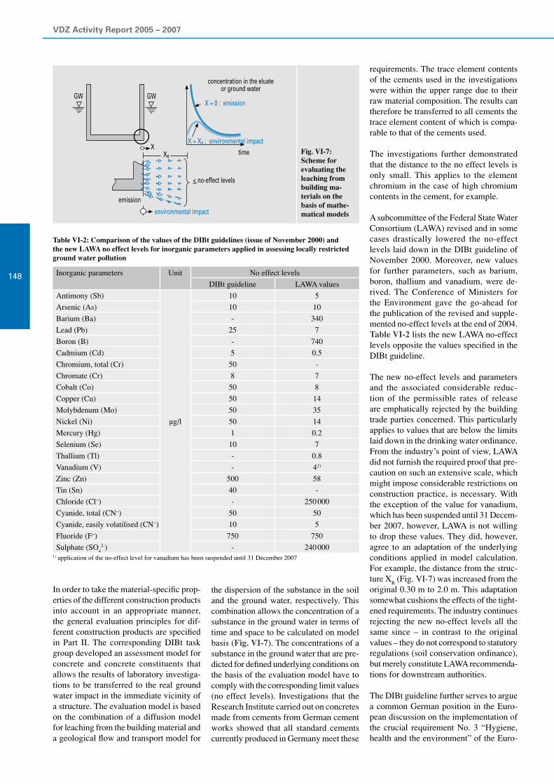
VDZ Activity Report 2005 – 2007
148
In order to take the material-specific prop-erties of the different construction products into account in an appropriate manner, the general evaluation principles for dif-ferent construction products are specified in Part II. The corresponding DIBt task group developed an assessment model for concrete and concrete constituents that allows the results of laboratory investiga-tions to be transferred to the real ground water impact in the immediate vicinity of a structure. The evaluation model is based on the combination of a diffusion model for leaching from the building material and a geological flow and transport model for
Fig. VI-7: Scheme for evaluating the leaching from building ma-terials on the basis of mathe-matical models
Inorganic parameters Unit No effect levels
DIBt guideline LAWA values
Antimony (Sb)
µg/l
10 5
Arsenic (As) 10 10
Barium (Ba) - 340
Lead (Pb) 25 7
Boron (B) - 740
Cadmium (Cd) 5 0.5
Chromium, total (Cr) 50 -
Chromate (Cr) 8 7
Cobalt (Co) 50 8
Copper (Cu) 50 14
Molybdenum (Mo) 50 35
Nickel (Ni) 50 14
Mercury (Hg) 1 0.2
Selenium (Se) 10 7
Thallium (Tl) - 0.8
Vanadium (V) - 41)
Zinc (Zn) 500 58
Tin (Sn) 40 -
Chloride (Cl−) - 250 000
Cyanide, total (CN−) 50 50
Cyanide, easily volatilised (CN−) 10 5
Fluoride (F−) 750 750
Sulphate (SO42-) - 240 000
1) application of the no-effect level for vanadium has been suspended until 31 December 2007
Table VI-2: Comparison of the values of the DIBt guidelines (issue of November 2000) and the new LAWA no effect levels for inorganic parameters applied in assessing locally restricted ground water pollution
the dispersion of the substance in the soil and the ground water, respectively. This combination allows the concentration of a substance in the ground water in terms of time and space to be calculated on model basis (Fig. VI-7). The concentrations of a substance in the ground water that are pre-dicted for defined underlying conditions on the basis of the evaluation model have to comply with the corresponding limit values (no effect levels). Investigations that the Research Institute carried out on concretes made from cements from German cement works showed that all standard cements currently produced in Germany meet these
requirements. The trace element contents of the cements used in the investigations were within the upper range due to their raw material composition. The results can therefore be transferred to all cements the trace element content of which is compa-rable to that of the cements used.
The investigations further demonstrated that the distance to the no effect levels is only small. This applies to the element chromium in the case of high chromium contents in the cement, for example.
A subcommittee of the Federal State Water Consortium (LAWA) revised and in some cases drastically lowered the no-effect levels laid down in the DIBt guideline of November 2000. Moreover, new values for further parameters, such as barium, boron, thallium and vanadium, were de-rived. The Conference of Ministers for the Environment gave the go-ahead for the publication of the revised and supple-mented no-effect levels at the end of 2004. Table VI-2 lists the new LAWA no-effect levels opposite the values specified in the DIBt guideline.
The new no-effect levels and parameters and the associated considerable reduc-tion of the permissible rates of release are emphatically rejected by the building trade parties concerned. This particularly applies to values that are below the limits laid down in the drinking water ordinance. From the industry’s point of view, LAWA did not furnish the required proof that pre-caution on such an extensive scale, which might impose considerable restrictions on construction practice, is necessary. With the exception of the value for vanadium, which has been suspended until 31 Decem-ber 2007, however, LAWA is not willing to drop these values. They did, however, agree to an adaptation of the underlying conditions applied in model calculation. For example, the distance from the struc-ture X
R (Fig. VI-7) was increased from the
original 0.30 m to 2.0 m. This adaptation somewhat cushions the effects of the tight-ened requirements. The industry continues rejecting the new no-effect levels all the same since – in contrast to the original values – they do not correspond to statutory regulations (soil conservation ordinance), but merely constitute LAWA recommenda-tions for downstream authorities.
The DIBt guideline further serves to argue a common German position in the Euro-pean discussion on the implementation of the crucial requirement No. 3 “Hygiene, health and the environment” of the Euro-
GW GW
concentration in the eluateor ground water
X = 0 : emission
X = XR : environmental impacttime
emission
environmental impact
XXR
< no-effect levels

VI Environmental compatibility of cement and concrete
149
pean Construction Products Directive. The DIBt had consented not to initiate the notification procedure until a version agreed on with the industry was available. Violating this agreement, the DIBt initiat-ed this procedure at short notice in early 2006. As the “Fundamental principles for evaluating the effects of construction pro-ducts on the soil and the ground water Part I (draft April 2005) and Part II (draft De-cember 2005)” that were filed comprise the new LAWA no-effect levels, for example, the industry party unanimously rejected these documents at the latest meeting of the corresponding “Soil and groundwater” DIBt task group held in September 2006. It remains to be seen whether a solution that is satisfactory to both sides will emerge during further discussions.
Cement-based materialsin drinking water
European acceptance scheme for construction products in contact with drinking waterDrinking water is the most important sus-tenance and as such must not suffer any impermissible losses in quality on its way to the point where it is tapped by the con-sumer. Accordingly, particular importance is conferred on the materials used in the storage and distribution of drinking water. Cement-based materials have proved that they are excellently suited for all domains of the drinking water supply for decades. The European Drinking Water Directive specifies minimum requirements for drink-ing water applicable in all EU member states. Drinking water hygiene special-ists therefore strove to harmonise also the requirements for materials in contact with drinking water. To that end, drinking water hygiene specialists authorised by the EU member states have been working on a “European Acceptance Scheme (EAS)” in the “Regulators Group for Construction Products in Contact with Drinking Water (RG-CPDW)” since 1999. This work is based on mandate M/136, which refers both to the Construction Products Direct-ive and the Drinking Water Directive. The EAS was to apply to all materials that come into contact with drinking water (plastics, metals, cement-based materials, etc.). The acceptance scheme to be worked out was to ensure the preservation of existing national consumer protection levels and the continued application of all common, proven materials.
After the Regulators Group had worked on the EAS for about five years, it was found not have any legal foundations in the year 2004. The Regulators Group was therefore converted to an experts group that does not have any regulatory or de-cision-making competence, but only an advisory function for the Commission. It was further stated that the European Con-struction Products Directive only covers construction products that correspond to a harmonised technical specification and that the requirements to be placed on these products are left to the individual member states’ discretion. Thus, only the test meth-ods for construction products in contact with drinking water could be harmonised. Approved, harmonised test methods could, however, considerably lessen the cost and effort to be expended by the industry as it would no longer be necessary to consider different national methods of testing. In-stead, a test result would be evaluated on the basis of the corresponding national requirements.
This change in underlying conditions was to be taken into account in the revision of mandate M/136 performed in the period under review. Many aspects of the revised mandate, such as the scope of the EAS or the construction products to be included, were so contradictory, however, that the CEN rejected it in late 2006. Thus, it re-mains to be seen whether the Commission can remedy these contradictions.
The three RG-CPDW subgroups for plas-tics, metals and cement-based materials continued their work regardless of these fundamental questions. They were merely renamed expert subgroups. Furthermore, a new subgroup for composite products, such as taps, valves and pumps, was set up.
The subgroup for the field of cement-based materials primarily discussed the approved constituent list proposed by CEN/TC 104 “Concrete and related products”. These constituents can be applied in concrete production without testing. The aim pur-sued by the ACL concept is to reduce the scope of testing required for construction products in contact with drinking water to the extent that is actually necessary. The ACL currently consists of a catalogue of constituents, such as cements, aggregates, concrete additions, concrete admixtures, etc., that have a tradition of use in the drink-ing water domain and are approved for that purpose in at least one EU member state.
The EU Commission has already agreed to the ACL concept. It was summarised in a Commission paper together with similar lists for plastics (positive list) and metals (composition list) and submitted to the Standing Committee on Construction for information. It is not foreseeable yet what status will be conferred on the ACL and the other lists in the future and what committee or expert group, respectively, will have the say about these lists. From the Research Institute’s point of view, the ACL concept affords a sound basis for further activities in the drinking water sector. The concept might further serve as a model for estab-lishing criteria for the classification as WT products. These form part of the work of CEN/TC 351 on the emission of regulated hazardous substances to the interior air, the soil, the surface and the ground water.
DVGW worksheet W 347Worksheet W 347 “Hygiene requirements applying to cement-based materials in the drinking water sector – testing and evalu-ation”, which the German Technical and Scientific Association for Gas and Water (DVGW) issued in October 1999, is the first regulation ever established to take into account the special properties of cement-based materials in contact with drinking water in an appropriate manner. The in-troduction of the European standards for cement, aggregates, concrete admixtures etc. and the work of ad hoc group AHG 6 “Influence of cement-based products on water intended for human consumption” of working group WG 3 of CEN/TC 164 “Water supply” prompted the start of revi-sion work on the Worksheet as early as in 2002. The May 2006 issue of Worksheet W 347 comprises adaptations to the state of the art and the corresponding European conformity evaluation standards. More-over, the experiences and findings of the testing institutes involved found their way into the revised version. Thus, taste test-ing was dispensed with, and the testing of TOC release from structures located in drinking water protection zones is no longer required.
In accordance with Worksheet W 347, ce-ments conforming to EN 197-1 and DIN 1164 as well as cements approved by the building inspectorate and calcium alumi-nate cements conforming to EN 14647 can be applied. This statement only relates to their basic eligibility, however. The Work-sheet further specifies how the suitability of these cements and the products made
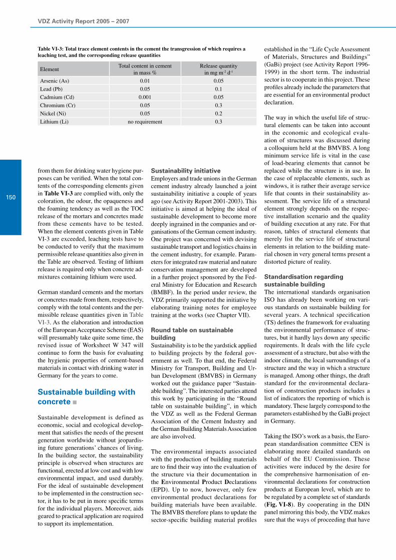
VDZ Activity Report 2005 – 2007
150
from them for drinking water hygiene pur-poses can be verified. When the total con-tents of the corresponding elements given in Table VI-3 are complied with, only the coloration, the odour, the opaqueness and the foaming tendency as well as the TOC release of the mortars and concretes made from these cements have to be tested. When the element contents given in Table VI-3 are exceeded, leaching tests have to be conducted to verify that the maximum permissible release quantities also given in the Table are observed. Testing of lithium release is required only when concrete ad-mixtures containing lithium were used.
German standard cements and the mortars or concretes made from them, respectively, comply with the total contents and the per-missible release quantities given in Table VI-3. As the elaboration and introduction of the European Acceptance Scheme (EAS) will presumably take quite some time, the revised issue of Worksheet W 347 will continue to form the basis for evaluating the hygienic properties of cement-based materials in contact with drinking water in Germany for the years to come.
Sustainable building with concrete
Sustainable development is defined as economic, social and ecological develop-ment that satisfies the needs of the present generation worldwide without jeopardis-ing future generations’ chances of living. In the building sector, the sustainability principle is observed when structures are functional, erected at low cost and with low environmental impact, and used durably. For the ideal of sustainable development to be implemented in the construction sec-tor, it has to be put in more specific terms for the individual players. Moreover, aids geared to practical application are required to support its implementation.
ElementTotal content in cement
in mass %Release quantity
in mg m-2 d-1
Arsenic (As) 0.01 0.05
Lead (Pb) 0.05 0.1
Cadmium (Cd) 0.001 0.05
Chromium (Cr) 0.05 0.3
Nickel (Ni) 0.05 0.2
Lithium (Li) no requirement 0.3
Table VI-3: Total trace element contents in the cement the transgression of which requires a leaching test, and the corresponding release quantities
Sustainability initiativeEmployers and trade unions in the German cement industry already launched a joint sustainability initiative a couple of years ago (see Activity Report 2001-2003). This initiative is aimed at helping the ideal of sustainable development to become more deeply ingrained in the companies and or-ganisations of the German cement industry. One project was concerned with devising sustainable transport and logistics chains in the cement industry, for example. Param-eters for integrated raw material and nature conservation management are developed in a further project sponsored by the Fed-eral Ministry for Education and Research (BMBF). In the period under review, the VDZ primarily supported the initiative by elaborating training notes for employee training at the works (see Chapter VII).
Round table on sustainable buildingSustainability is to be the yardstick applied to building projects by the federal gov-ernment as well. To that end, the Federal Ministry for Transport, Building and Ur-ban Development (BMVBS) in Germany worked out the guidance paper “Sustain-able building”. The interested parties attend this work by participating in the “Round table on sustainable building”, in which the VDZ as well as the Federal German Association of the Cement Industry and the German Building Materials Association are also involved.
The environmental impacts associated with the production of building materials are to find their way into the evaluation of the structure via their documentation in the Environmental Product Declarations (EPD). Up to now, however, only few environmental product declarations for building materials have been available. The BMVBS therefore plans to update the sector-specific building material profiles
established in the “Life Cycle Assessment of Materials, Structures and Buildings” (GaBi) project (see Activity Report 1996-1999) in the short term. The industrial sector is to cooperate in this project. These profiles already include the parameters that are essential for an environmental product declaration.
The way in which the useful life of struc-tural elements can be taken into account in the economic and ecological evalu-ation of structures was discussed during a colloquium held at the BMVBS. A long minimum service life is vital in the case of load-bearing elements that cannot be replaced while the structure is in use. In the case of replaceable elements, such as windows, it is rather their average service life that counts in their sustainability as-sessment. The service life of a structural element strongly depends on the respec-tive installation scenario and the quality of building execution at any rate. For that reason, tables of structural elements that merely list the service life of structural elements in relation to the building mate-rial chosen in very general terms present a distorted picture of reality.
Standardisation regarding sustainable buildingThe international standards organisation ISO has already been working on vari-ous standards on sustainable building for several years. A technical specification (TS) defines the framework for evaluating the environmental performance of struc-tures, but it hardly lays down any specific requirements. It deals with the life cycle assessment of a structure, but also with the indoor climate, the local surroundings of a structure and the way in which a structure is managed. Among other things, the draft standard for the environmental declara-tion of construction products includes a list of indicators the reporting of which is mandatory. These largely correspond to the parameters established by the GaBi project in Germany.
Taking the ISO’s work as a basis, the Euro-pean standardisation committee CEN is elaborating more detailed standards on behalf of the EU Commission. These activities were induced by the desire for the comprehensive harmonisation of en-vironmental declarations for construction products at European level, which are to be regulated by a complete set of standards (Fig. VI-8). By cooperating in the DIN panel mirroring this body, the VDZ makes sure that the ways of proceeding that have

VI Environmental compatibility of cement and concrete
151
established themselves in Germany and are considered reasonable are adopted in Euro-pean standardisation as well. Moreover, the sustainability assessment of a structure has to constitute a balanced appraisal of the environmental aspects considered as well as economic and social aspects. Furthermore, the technical properties of the structure have to be appropriately taken into account.
Sustainable concrete constructionGiven its performance capacity, its wide range of applications and the large quan-tities of building materials used, concrete construction assumes a pre-eminent posi-tion in the building sector. This is why the implementation of sustainable concrete construction is of particular importance. The German Committee for Structural Concrete (DAfStb) will prepare “Guide-lines for sustainable building with concrete (GrunaBau)” in the medium term. This paper is to provide all parties involved in concrete construction with evaluation rules and technical recommendations for sustain-able building with concrete. Furthermore, the document is to create provisions for sustainable concrete construction that are to be adopted directly in the future national and international standards and directives on concrete construction. In this context, the entire life cycle of a concrete structure, i.e. starting from the production of the in-put materials, via the erection and use of the structure, and up to its dismantling and recycling, will be relevant. In conjunction with developing GrunaBau, the DAfStb initiated a joint project on “Sustainable building with concrete”, which is spon-sored by the Federal Ministry for Education and Research (BMBF).
Utilisation of concrete crusher sandDuring the first phase of the joint project, the potential of reducing costs and environ-mental impacts that is inherent in alterna-tive material use in concrete construction was investigated as part of a sub-project under the overall control of the Research Institute.
Taking the potential use of concrete crusher sand as a alternative material in cement clinker manufacture as an example, the work performed shows how sustainability assessment can be integrated in the assess-ment of its possible uses that was common even before. Concrete crusher sand with a grading of 0 to 2 mm is obtained when recycled aggregates are generated from crushed concrete. In contrast to coarser aggregates, however, it can usually not be
Fig. VI-8: Future international standardisation of environmental declarations of building products (planned standards for the sustainability assessment of structures are not shown)
utilised in concrete without further process-ing for concrete technology reasons. The potential use of concrete crusher sand as a raw material in cement clinker production would allow the complete and high-grade recycling of the concrete. Uncarbonated hardened cement paste in the concrete crusher sand may additionally result in CO
2 reduction.
As expected, chemical analyses of concrete crusher sands available in Germany yielded a very high silicon content largely deriv-ing from the sand portion of the recycled concrete. The chemical composition of the concrete crusher sands reviewed in the investigations described below is given in Table VI-4. In cement clinker production, these materials can primarily be utilised as a substitute for sand, which accounts for
Concrete crusher sand
No. 1 No. 1L No. 1F No. 2 No. 3 No. 4 No. 5
SiO2
80.44 71.09 54.73 79.51 72.74 62.03 55.43
Al2O
36.07 6.95 10.11 5.60 4.38 6.07 3.37
Fe2O
32.02 2.04 3.62 2.30 2.02 2.24 1.64
CaO 5.69 12.27 21.48 9.08 16.81 23.94 36.81
MgO 1.72 2.72 3.59 0.76 1.42 2.41 0.76
an average of 3% of the raw material mix in Germany. Crusher sands with a higher calcium oxide proportion can additionally be substituted for calcium agents.
The effects that the use of concrete crusher sand has on cement clinker production were determined by computer-aided simulation of the clinker burning process. This simula-tion allows assessment of the process and plant technology process variables, such as energy and material flows within the kiln system. Moreover, statements on the influence of concrete crusher sand use on the energy consumption and the emissions of cement clinker production in particular can be made. The first step of the simu-lation studies consisted of calculating a reference scenario based on the use of a typical raw material mix without crusher
Table VI-4: Chemical composition of the concrete crusher sands (Nos. 1 to 5) and the fractions generated from crusher sand No. 1 (light-weight fraction 1L and finest fraction 1F), givenin mass %, loss-on-ignition-free
CEN standardisation
EN (planned): Use of environmental declarations of building products
EN (planned): Communication formats for environmental declarations of building products
EN (planned): Product Category Rules[Rules for establishing environmental declarations]
TR (planned): Generic data for theestablishment of an environmental declaration
ISO/DIS 21930 (draft standard): Environmental declarations of building products
ISO 14025: Type III environmental declarations
ISO standardisation

VDZ Activity Report 2005 – 2007
152
sand. Proceeding from this basis, part of the reference raw material was substituted by various concrete crusher sands, and the production of the cement clinkers was calculated. Product quality, such as the content of important clinker phases, as well as aspects of process and plant technology, such as the temperatures to be achieved in important sections of the kiln system, were taken into account in this process. A comparison of the variations calculated and the reference scenario yields reduc-tion potentials of more than 2% regarding energy consumption and CO
2 emissions
in some cases.
By further including processes that took place in the previous history, e.g. the gen-eration of the electrical power required, the corresponding sustainability indica-tors “primary energy, not renewable” and “greenhouse warming potential” can be calculated (Fig. VI-9). In practical applica-tion, the coincidence of demand for a sili-con agent at the cement works and supply of crusher sand from a suitable processing plant will represent the main opportunity of realising these reduction potentials. During the second project phase, the underlying conditions for particularly promising uti-lisation will be explored. This also serves the purpose of incorporating in GrunaBau the general requirements of sustainable alternative material use that meets practi-cal demands.
Measuring and testingmethods
Highly efficient analysis equipment is indispensable for determining the con-tent of regulated dangerous substances in products or their possible release during product manufacture or from products, respectively. The Research Institute has had corresponding analysis equipment at its disposal for many years. Originally, the inorganic and organic trace analysis carried out at the Research Institute was mainly used in research projects or to set-tle analytical questions. In the past decade, however, the demand for analysis work that the Research Institute performs as a service provider has risen continually.
The increase in the share of contract services in the overall service portfolio requires equipment that not only ensures high quality, but also allows orders to be processed quickly. The pool of instruments for inorganic and organic trace analysis in the Research Institute’s various analysis laboratories was therefore rejuvenated and expanded. The ICP and GC mass spectrom-eters were replaced by new high-perform-ance analytical devices. A further instru-ment for mercury emission measurement was bought to manage the continuous rise in the number of mercury analyses of the past years. In this way, the Research In-stitute’s analytical service portfolio was extended significantly.
Fig. VI-9: Potential change in the sustainability indicators “primary energy, non-renewable” and “greenhouse warming potential” due to the use of various concrete crusher sands (Nos. 1 to 5) and the fractions generated from crusher sand No. 1 (light-weight fraction 1L and finest fraction 1F) in a typical cement clinker burning process
Reconciling quality and quantityThe determination of inorganic and organic trace constituents continues to be a very demanding field of quantitative analytical chemistry. The trace analysis equipment at the Research Institute of the Cement Industry was initially geared to elaborat-ing strategies for upscale analyses rather than to high throughput. As the number of clients grew, so did the requirements placed on sample throughput and processing time. Higher sample throughput must, however, not have any adverse impact on the qual-ity of analysis results. Today’s clients need verifiable analysis results made available quickly. At the Research Institute, this is accomplished not only by means of highly efficient analysers, but also by the proven cooperation of the individual departments and the close proximity of experts.
Emission analysis and materials balance as key topicsEmission monitoring is one of the focal areas of application for the new analysis instruments. The large number of samples that the Research Institute’s Emission moni-toring body takes during emission measure-ments at the cement works is analysed for metal and semi-metal trace elements by the ICP mass spectrometer (ICP-MS). A GC mass spectrometer (GC-MS) serves to determine organic emission constituents.
The number of samples for mercury emis-sion measurement rose considerably over the past years. This can be traced back to the required calibrations of stationary analysers for continuous mercury emission measurement, which the Research Institute accompanies by discontinuous mercury emission measurements. A second mercury analysis instrument was purchased to man-age this increase in the sample volume.
Furthermore, the high sensitivity of the analysers is indispensable in the establish-ment of materials balances for industrial plants in which trace constituents are in-cluded. The contents of trace constituents in the starting materials are often very low, while they may build up consider-ably in individual material sub-flows. To draw up a conclusive materials balance the constituents of interest have to be de-tected correctly in all material sub-flows. This requires highly efficient and reliable analysis instruments.
1
Devia
tion
from
the r
efer
ence
scen
ario
in %
primary energy, non-renewablegreenhouse warming potential
2
1
0
-1
-2
-3
1L 1F 2 3 4 5

VI Environmental compatibility of cement and concrete
153
Service portfolio extendedOwing to improved technology, the new analysers allow the measuring of samples with fewer interferences occurring, and the required corrections of measurement interferences to be carried out automati-cally and software-controlled. Given its new, patented “ion mirror”, the new ICP mass spectrometer (Fig. VI-10) is cap- able of measuring more elements than its predecessor model. In this way, the number of proficiency measurements that has to be conducted with other metal/semi-metal analysis methods, such as AAS, is reduced. With the new GC mass spectrometer, which can be operated in the MS/MS mode, the Research Institute will be able to identify additional trace constituents in the future (Fig. VI-11). In addition to the determina-tion of simple aromatic-organic emission constituents (BTEX), also quantitative PCB, PAH and pesticide analyses as well as qualitative analyses for various samples that may be very difficult to analyse can now be offered.
Fig. VI-10: Sample inlet system of the new ICP mass spectrometer
Fig. VI-11:View of the cou-pled quadrupole mass separators of the new GC mass spectrom-eter

VDZ Activity Report 2005 – 2007
154 Responsibility for employees
VII
The evaluation of accident scenarios promotes safety at work
Promoting safety at work in the factories is one of the VDZ’s constitutional functions. Developing and introducing measures to improve safety at work is one of the responsibilities of the VDZ’s Environment And Plant Technology Committee, which is supported in its work principally by the VDZ’s Safety At Work Working Group and the Research Institute. Accident statistics for German member plants have been recorded and statistically analysed since 1965. The Research Institute has run a safety at work competition on the basis of these figures every year since 1974, with awards for the plants with the best safety record. Cooperating with the Research Institute, the Safety At Work Working Group further drew up safety codes of practice and safety checklists and discussed topical safety problems during factory visits. These contributed to an improvement in industrial safety in the factories. In particular, the working group elaborated a code of practice on recommended instructions for cement works employees and dealt with the implementation of the new Ordinance on Hazardous Substances.
As part of the advanced training programme for cement works employees, the VDZ offers training courses and seminars. The 22nd “lime/cement” industrial foremen’s training course with twelve participants was successfully concluded in cooperation with the Düsseldorf Chamber of Industry and Commerce during the period under review. At the beginning of 2007, the VDZ can thus look back on 49 years of successful training of industrial foremen. A total of 820 persons have been successfully trained on 30 courses during this period.
Moreover, the development programme for production controllers has been continued. One course with a total of 15 participants was carried out during the period under review. Since 1998, the VDZ’s development programme has been expanded to include a series of one-day and extended seminars in addition to the courses for industrial foremen and production controllers and the safe-ty at work seminars that were already running. These cover chemical analysis, ambient pollution control and environmental tech-nology, the process technology of cement manufacture, the surveillance of cement quality, as well as the fundamentals of concrete technology and concrete processing. In each of the years 2005 and 2006 eight seminars were held. Seven more seminars are plan-ned for 2007.

VII Responsibility for employees
155

VDZ Activity Report 2005 – 2007
156
Safety at work
Improving safety at work in the factories of the cement industry is one of the VDZ’s constitutional functions. Efforts at plant level and at the Research Institute are there-fore a priority area for the association. The VDZ’s Environment And Plant Technology Committee develops and initiates measures to improve safety at work, and is effectively supported in its work principally by the VDZ’s Safety At Work Working Group. The common goal of all this effort is to motivate employees at cement works to be safety conscious, to inform them regularly about ways of improving safety at work, and to encourage them to constantly review safety in the workplace.
The industrial safety measures taken at the works as well as the cooperation with the VDZ and its Research Institute have con-tributed notably to reducing the accident rate in German cement works to one third over the past 30 years. As early as in 1984, the accident rate for all employees was at the very low level of about 20 accidents per one million working hours. The rate was in line with that of the chemical industry. In the year 2006, the average accident rate for the German cement industry was some 64% below the accident rate of all member companies of the Quarry Employers’ Li-ability Insurance Association (StBG), and around 37% below the average accident rate for trade and industry as a whole. The comparison of accident figures for all member companies of the StBG was based on the number of full-time workers in the organisation; for example a full-time worker completed about 1 570 hours per year in 2005.
The economic significance of safety at work is best illustrated by the percentage of lost time attributable to accidents at work. Whereas 30 years ago a mean relative lost time of approximately 0.81% was attribut-able to reportable accidents at work, this figure was down to 0.3% in 2005.
VDZ accident statisticsFigures for reportable industrial and transport accidents for German member plants have been recorded and statistically analysed by the Research Institute every year since 1965. The main results and key accident statistics for the years 2005 and 2006 are summarised in Table VII-1. For purposes of comparing and characterising the accident rate trend, the first column of the table also shows the corresponding
figures for the year 1969, the first year in which accident statistics were analysed in the cement industry. From 1993 onwards, the calculation is based on the whole work-force of the plant rather than on industrial workers to take account of the changing personnel structure in the plants. Plant headcount declined by approx. 0.9% in the year 2005, and by 7.1% in the year 2006 in a year-on-year comparison. The number of working hours completed fell by 3.1% in 2005 and by approx. 6.4% in 2006.
For that reason, the number of hours worked annually per employee decreased from about 1 680 in 2004 to 1 643 in 2005. At 1 654, the number of hours worked per employee was slightly higher in 2006. It can be seen from the table that output edged up from 31.0 million t in 2005 to 31.9 million t in 2006 during the period under review. This results in production-related working hours of 0.28 h/t in the year 2005 and 0.26 h/t in the year 2006. The number of reportable industrial accidents rose from 96 in 2005 to 121 in 2006, which corresponds to a climb of approx. 26%. The average accident rate (number of reportable industrial accidents per 1 million hours worked) of 10.91 recorded for all plants
Year 1969 2005 2006
Number of works covered 98 50 50
Cement production in millions of tons 34.3 31.0 33.51)
Plant headcount
Number of employees 15 190 5 356 4 975
Hours worked 31 339 177 8 798 507 8 228 340
Production-related workinghours in h/t
0.91 0.28 0.25
Reportable industrial accidents 1 376 96 121
Accident rate(accidents per 1 million hours worked)
43.90 10.91 14.71
Calendar days lost as a result of reportable industrial accidents
31 935 3 518 3 645
Working days lost per employee 2.10 0.66 0.73
Calendar days lost per industrial accident 23.20 36.65 30.12
“100-men-rate”(accidents per 100 employees)
9.10 1.79 2.43
Reportable transport accidents 180 17 15
Calendar days lost as a resultof reportable transport accidents
5 822 288 638
Accident rate of the entire workforce 37.70 9.51 12.38
Table VII-1: Accident statistics for the workforce employed at the VDZ member works in the years 1969, 2005 and 2006
in 2005 was the lowest rate ever achieved. Given the increase in the number of acci-dents, the accident rate for the year 2006 was considerably higher at 14.71.
A 0.0 accident rate was achieved by eleven clinker-producing plants both in 2005 and in 2006 (Fig. VII-1 and Table VII-2). The accident figures for industrial work-ers and all employees combined were 9.51 for the year 2005 and 12.38 for 2006, respectively.
The average number of calendar working days lost due to reportable accidents at work declined from 36.65 in 2005 to 30.12 in 2006, which corresponds to a 17.8% drop. The economic significance of ac-cidents at work can also be assessed using the number of working days lost per year. This figure gives the number of calendar working days lost as a result of reportable industrial accidents related to the plant headcount. The mean number of working days lost grew from 0.66 in 2005 to 0.73 in 2006. At 1.79, the pattern of the “100 men rate” (the number of industrial accidents per 100 employees) reached its lowest level ever in 2005. It rose to 2.43 in the year 2006. By contrast the “100 men rate”
1) preliminary figure

VII Responsibility for employees
157
Table VII-2: Winners of the VDZ industrial safety competition for clinker-producing works in the years 2005 and 2006
Fig. VII-1: Presentation of the awards to the winners of the 2005 VDZ industrial safety competition
for the companies insured with the StBG was only 4.72 in 2005, which corresponds to an accident frequency rate of 30.10. The number of reportable transport accidents during the period under review fluctuated between 17 in 2005 and 15 in 2006.
Promoting safety at workSix safety codes of practice (Nos.100 to 105) describing typical and especially sig-nificant industrial accidents and six safety checklists (Nos. 80 to 85) for checking equipment and measures for improving safety at work in various areas were pub-lished in the last two years. For 28 years now awards have been granted to those clinker-producing member works with the lowest accident rates. The award consists of a plaque and the VDZ safety symbol with the inscription “Safe working – VDZ”. The plaque constitutes recognition of the efforts by plant management and workforce to ensure safety at work. The award is also in-tended to motivate employees and to raise safety awareness in the factories.
Since the hazard potential in clinker-pro-ducing works is quite different from that for employees in works without clinker production, there is a limit to how far a standard measure can be applied to assess safety standards at all works. In order to provide motivation to improve safety at work in grinding and blending plants, a special safety competition has been intro-duced for this group of plants from 1995. A special certificate is awarded to the grind-ing and blending plants with the lowest accident rates.
Safety seminarsThe pattern of accident statistics for recent years clearly shows that safety at work improved markedly as a consequence of the substantial efforts made at plant level with the support of the working group and the Research Institute. However, to continually improve safety at work there must be no slackening in the efforts made by all employees, and in fact they must be further intensified. The key factor is em-ployee motivation to correctly apply plant safety rules, and to actively implement them. This is primarily the responsibility of works management – works managers, plant managers and especially foremen and chargehands. The industrial foreman is in constant contact with his team, and as a role model has the greatest influence on improving safety at work. In the light of this, the VDZ has offered intensive training courses for practising foremen and supervi-sors on the recommendation of the Safety At Work Working Group. The aim of the
2005 2006
1st place CEMEX WestZement GmbHBeckum-Mersmann worksAccident rate: 0.0
CEMEX WestZement GmbHBeckum-Kollenbach worksAccident rate: 0.0
CEMEX OstZement GmbHRüdersdorf worksAccident rate: 0.0
CEMEX WestZement GmbHBeckum-Mersmann worksAccident rate: 0.0
Dyckerhoff AGGeseke worksAccident rate 0.0
Dyckerhoff AGAmöneburg worksAccident rate: 0.0
Dyckerhoff AGGöllheim worksAccident rate 0.0
Dyckerhoff AGGeseke worksAccident rate 0.0
Dyckerhoff AGLengerich worksAccident rate 0.0
Dyckerhoff AGGöllheim worksAccident rate 0.0
Dyckerhoff AGNeubeckum worksAccident rate 0.0
HeidelbergCement AGLengfurt worksAccident rate 0.0
HeidelbergCement AGBurglengenfeld worksAccident rate 0.0
Holcim (Deutschland) AGHöver worksAccident rate 0.0
HeidelbergCement AGSchelklingen worksAccident rate 0.0
Lafarge Zement Karsdorf GmbHSötenich worksAccident rate 0.0
Lafarge Zement Karsdorf GmbHSötenich worksAccident rate 0.0
Lafarge Zement Wössingen GmbHAccident rate: 0.0
Schwenk Zement KGAllmendingen worksAccident rate: 0.0
Schwenk Zement KGMergelstetten worksAccident rate: 0.0
Schwenk Zement KGMergelstetten worksAccident rate: 0.0
Teutonia Zementwerk AGAccident rate: 0.0
2nd place CEMEX WestZement GmbHBeckum-Kollenbach worksAccident rate: 4.61
Lafarge Zement Karsdorf GmbHKarsdorf worksAccident rate 3.48
3rd place HeidelbergCement AGWetzlar worksAccident rate: 5.90
Deuna Zement GmbHAccident rate: 3.81

VDZ Activity Report 2005 – 2007
158
seminars is to improve knowledge of safe working practices, especially in high-risk areas, to highlight significant accidents and convey suggestions for direct action to improve safety at work. The seminars are provided jointly by the Quarry Employers’ Liability Insurance Association (StBG) and the VDZ. They are arranged jointly by the VDZ’s Safety At Work Working Group and the StBG, last approximately two days and are organised and carried out off-site in groups of 15 to 20 participants by StBG seminar leaders. The seminars have been offered since 1993 on a regular basis with six seminars per year. The speakers are qualified StBG staff. The course content is periodically reviewed, and is compiled and prepared principally by the VDZ’s Safety At Work Working Group.
New Ordinance on Hazardous SubstancesThe new Ordinance on Hazardous Sub-stances took effect on 1 January 2005 and has to be implemented now. In terms of content, the main emphasis of the new Ordinance on Hazardous Substances is placed on procuring information for clas-sifying the hazard potential of a substance and a hazard assessment for work involving the handling of these substances. Depend-ing on the hazard potential of a substance or the corresponding work, respectively, the substances are to be assigned to four protection levels. The new Ordinance on Hazardous Substances further extends to cover industrial medicine examinations and replaces the workplace limit values previously derived from technical aspects by risk-related values.
To implement the new Ordinance on Haz-ardous Substances, it is recommendable to first update the list of hazardous sub-stances and check whether it is complete, respectively, and to procure correspond-ing current safety datasheets for the sub- stances. Moreover, the quantities available or stocked maximally, respectively, have to be recorded and assigned to the employees handling the substances. According to the Ordinance on Hazardous Substances, the substances have to be assigned to protec-tion levels. Furthermore, R- and S-phrases, hazardous material labelling, waste codes, water pollution classes and explosion pa-rameters should be included in the list of hazardous substances, and reference to the existing operating instructions should be made. The operating instructions regarding
hazardous substances should be updated in the wake of the classification of hazardous substances at protection levels as well.
After information has been procured and the R-phrases as well as the S-phrases, if applicable, have been evaluated in particu-lar, assignment to a protection level can be-gin, and corresponding precautions can be specified. Risks occurring from exposure to heat or cold also have to be taken into account in this process.
Updated safety datasheet 2005Legislative changes, such as the imple-mentation of the European “Chromate Directive” 2003/53/EC, necessitated an adaptation of the customary safety data-sheets. The content of the updated safety datasheet was adopted upon consultation with representatives of manufacturers’ associations (construction chemicals, mortar) and industrial safety authorities. The model safety datasheet harmonised at national level that was thus created ap-plies to chromate-reduced cements and chromate-reduced cementitious mixtures. The most relevant modifications relate to the following items:
Marking with danger indication R43 “Possible sensitisation by skin contact” will be dispensed with for all chromate-reduced cements. It is pointed out in the safety datasheet, however, that the effectiveness of chromate reduction presupposes appropriate storage and observance of the shelf life.
The general limit value for the dust fraction passing the alveoles (A value) totals 3 mg/m3 according to the new regulation.
Cements and cementitious mixtures are to be marked with safety caution S39 “Wear appropriate safety goggles/face mask during work”. This piece of advice derives from the classification compris-ing danger indication R41 “Hazard of serious eye injuries” and was stipulated by industrial safety authorities.
Information on toxicology is more de-tailed.
A modified safety datasheet was also drawn up for cements containing chromate which are put on the market under the terms of a special regulation of the Chemicals Pro-hibition Ordinance. Both model safety datasheets are available for copying on the VDZ’s homepage.
VDZ training and development
Training courses for industrial foremenThe VDZ runs training courses and semi-nars as development programmes for employees in cement works. It has been conducting foremen’s training courses in cooperation with the Dusseldorf Chamber of Industry and Commerce since 1958. By 1965, eight training courses had been held and a total of 274 industrial foremen had successfully completed the “cement” course. The specialist “lime/cement” in-dustrial foremen’s course that the VDZ has been running jointly with the Federal German Association of the Lime Industry since 1965 is unique in German-speaking countries. 546 delegates had successfully completed 22 “lime/cement” industrial foremen’s training courses by March 2007 (Fig. VII-2 and Table VII-3). In summary, the VDZ can look back on 49 years of suc-cessful industrial foremen’s training. The training courses are residential and used to be located at the training school in Dus-seldorf-Hassels. The Dusseldorf-Hassels training school will be closed down in mid-2007. The Institute for Public Administra-tion located in the town of Hilden south of Dusseldorf is an adequate, well-equipped training facility found in replacement. A survey was conducted in early 2007 to es-tablish the degree of interest by the works in a 23rd training course for industrial foremen, starting in the fall of 2007 and ending in March 2009. This training course would be residential again, taking place at the new training school.
Production controllers’ courseIn response to an increased level of quali-fications necessary for control room opera-tors, the VDZ decided in 1990 to organise production controllers’ training courses. These development programmes are de-signed to provide control room operators with state-of-the-art knowledge of process engineering and environmental technology in cement manufacturing and measure-ment, control and regulation technology in cement works. The aim is to make it easier for the control room operators to adapt to changes in production control resulting from automation and innovation, which will ensure reliable and effective opera-tion of the cement plant. The programme includes a theoretical section offered by the

VII Responsibility for employees
159
Course Year Cement Lime Total
Cement 1 to 8
1958/1959to
1964/1966229 45 274
Lime/cement 1 to 11
1965/1967to
1985/1987225 65 290
12
13
14
15
16
17
18
19
20
21
1987/1989
1989/1991
1991/1993
1992/1994
1993/1995
1995/1997
1997/1999
1999/2001
2001/2003
2003/2005
22
20
20
24
26
24
21
21
13
13
3
10
10
6
3
2
2
2
2
0
25
30
30
30
29
26
23
23
15
13
22 2005/2007 11 1 12
Total 215 41 256
Grand total 669 151 820
Fig. VII-2: “Lime/cement” industrial foremen after completion of the final examination in March 2007
Table VII-3: Number of graduates from the industrial foremen’s training courses
VDZ and a practical section that is carried out at the cement works. By 2006, a total of twelve training courses had been run, training 263 persons as “cement” produc-tion controllers. The next training course is being held from April to September 2007 at the Dusseldorf-Hassels training school. As the training school will be closed down afterwards, future training courses will also be held at the training facilities in Hilden mentioned above.
Training notesIn the past years, the VDZ’s “Training notes” task group compiled 47 training notes to be used in the development of industrial workers at the factories and in on-the-job-training of process mechanics. Following the completion of 16 training notes in the period under review, all train-ing notes planned are available now. The training notes are available both in digital format on CD and in printed form as a paper and transparency set, and can be obtained via the VDZ’s Internet homepage. Table VII-4 gives an overview of the training notes available. Examples of in-dividual training notes can also be seen on the VDZ’s intranet page.
The notes each comprise two parts, one consisting of text, the other consisting of pictures and charts (transparencies). They are to serve qualified staff members (in-structors) as a training aid. The topics these training notes deal with cover the entire process of cement manufacture, starting from raw material extraction and up to cement loading. The main focus is placed on those areas which relate to production processes at the works and are closely con-nected to the tasks performed by industrial workers.
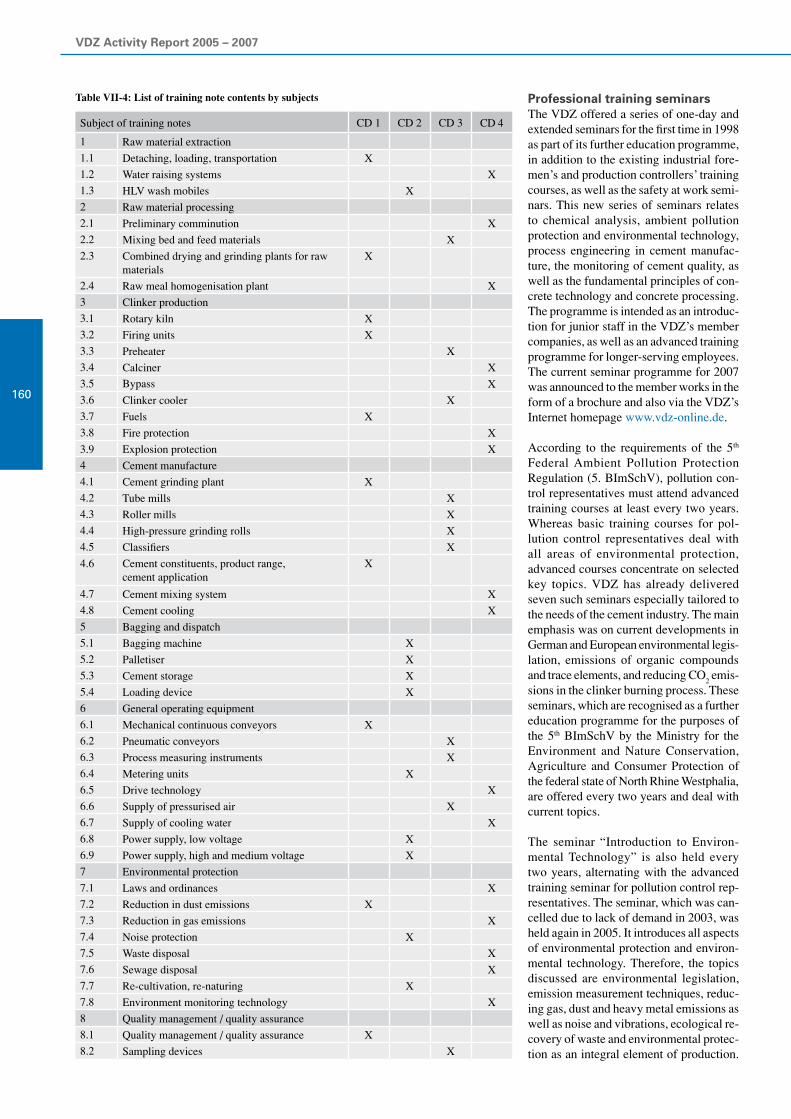
VDZ Activity Report 2005 – 2007
160
Subject of training notes CD 1 CD 2 CD 3 CD 4
1 Raw material extraction
1.1 Detaching, loading, transportation X
1.2 Water raising systems X
1.3 HLV wash mobiles X
2 Raw material processing
2.1 Preliminary comminution X
2.2 Mixing bed and feed materials X
2.3 Combined drying and grinding plants for raw materials
X
2.4 Raw meal homogenisation plant X
3 Clinker production
3.1 Rotary kiln X
3.2 Firing units X
3.3 Preheater X
3.4 Calciner X
3.5 Bypass X
3.6 Clinker cooler X
3.7 Fuels X
3.8 Fire protection X
3.9 Explosion protection X
4 Cement manufacture
4.1 Cement grinding plant X
4.2 Tube mills X
4.3 Roller mills X
4.4 High-pressure grinding rolls X
4.5 Classifiers X
4.6 Cement constituents, product range,cement application
X
4.7 Cement mixing system X
4.8 Cement cooling X
5 Bagging and dispatch
5.1 Bagging machine X
5.2 Palletiser X
5.3 Cement storage X
5.4 Loading device X
6 General operating equipment
6.1 Mechanical continuous conveyors X
6.2 Pneumatic conveyors X
6.3 Process measuring instruments X
6.4 Metering units X
6.5 Drive technology X
6.6 Supply of pressurised air X
6.7 Supply of cooling water X
6.8 Power supply, low voltage X
6.9 Power supply, high and medium voltage X
7 Environmental protection
7.1 Laws and ordinances X
7.2 Reduction in dust emissions X
7.3 Reduction in gas emissions X
7.4 Noise protection X
7.5 Waste disposal X
7.6 Sewage disposal X
7.7 Re-cultivation, re-naturing X
7.8 Environment monitoring technology X
8 Quality management / quality assurance
8.1 Quality management / quality assurance X
8.2 Sampling devices X
Table VII-4: List of training note contents by subjects Professional training seminarsThe VDZ offered a series of one-day and extended seminars for the first time in 1998 as part of its further education programme, in addition to the existing industrial fore-men’s and production controllers’ training courses, as well as the safety at work semi-nars. This new series of seminars relates to chemical analysis, ambient pollution protection and environmental technology, process engineering in cement manufac-ture, the monitoring of cement quality, as well as the fundamental principles of con-crete technology and concrete processing. The programme is intended as an introduc-tion for junior staff in the VDZ’s member companies, as well as an advanced training programme for longer-serving employees. The current seminar programme for 2007 was announced to the member works in the form of a brochure and also via the VDZ’s Internet homepage www.vdz-online.de.
According to the requirements of the 5th Federal Ambient Pollution Protection Regulation (5. BImSchV), pollution con-trol representatives must attend advanced training courses at least every two years. Whereas basic training courses for pol-lution control representatives deal with all areas of environmental protection, advanced courses concentrate on selected key topics. VDZ has already delivered seven such seminars especially tailored to the needs of the cement industry. The main emphasis was on current developments in German and European environmental legis-lation, emissions of organic compounds and trace elements, and reducing CO
2 emis-
sions in the clinker burning process. These seminars, which are recognised as a further education programme for the purposes of the 5th BImSchV by the Ministry for the Environment and Nature Conservation, Agriculture and Consumer Protection of the federal state of North Rhine Westphalia, are offered every two years and deal with current topics.
The seminar “Introduction to Environ-mental Technology” is also held every two years, alternating with the advanced training seminar for pollution control rep-resentatives. The seminar, which was can-celled due to lack of demand in 2003, was held again in 2005. It introduces all aspects of environmental protection and environ-mental technology. Therefore, the topics discussed are environmental legislation, emission measurement techniques, reduc-ing gas, dust and heavy metal emissions as well as noise and vibrations, ecological re-covery of waste and environmental protec-tion as an integral element of production.

VII Responsibility for employees
161
The lectures are supplemented by practical exercises on emission and environmental impact measurement techniques. This seminar is recognised by the government as a basic training course for prospective pollution control representatives.
The four-day “Young plant engineers” seminar aims to give the widest possible overview of all areas of cement manufac-ture up to the use of cement in concrete. Accordingly, the seminar deals in depth with process engineering subjects, chemi-cal/mineralogical questions, environmental law, environmentally compatible cement manufacture, environmental measuring technology, quality assurance and con-crete engineering. The seminar, which was previously held every year, has been offered every two years since 2004. After the seminar in 2006, the next one is sched-uled for 2008.
The seminar “From practical application – for practical application”, which was of-fered for the first time in 2005, is to extend the range of practice-oriented advanced training programmes. The seminar, which was held in 2006 and has been offered again in 2007, is primarily tailored to prac-tising industrial foremen and production controllers. Participants acquire profound knowledge of the latest trends in process engineering and cement manufacture. Pro-ceeding from this basis, the delegates are taught how to use the training notes in stag-ing training courses geared to operational practice for industrial workers.
Four seminars on the subject of cement quality monitoring are held every year. The
target group of these seminars are labora-tory managers and senior laboratory staff at the works. In the one-day seminar “X-ray fluorescence (XFA)”, in-depth knowledge on XF analysis techniques is conveyed to the participants. The two-day seminar “Technical mineralogy” gives a presenta-tion of how the chemical and mineralogical properties of cement raw materials, clinker, cement and concrete are determined using microscopy and X-ray diffractometry in-vestigation methods, and of how the results are to be evaluated. The main emphasis is placed on carrying out practical exercises and explaining the fundamental technical principles of the analysis systems. The two-day seminar “Testing according to EN 196” introduces the physical and chemical tests of cement and cement-type binders as well as raw materials and constituents, respec-tively, which are specified in the standard. Particular importance is attached to compli-ance with the work processes stipulated in the standard and the detection and avoid-ance of sources of error. The main focus of a further one-day seminar is the determi-nation of the blastfurnace slag content in cements by a combination of microscopic and chemical methods. This seminar has been complemented by a one-day seminar entitled “Determination of the blastfurnace slag content – overview of methods” since 2005. Participants gain an insight into the methods that can be applied to determine the blastfurnace slag content in cement.
In the field of cement application, the two-day seminar on “Fundamental principles of concrete engineering/durability of concrete and reinforced concrete elements” was of-fered in the years 2005 and 2007. In the
first part of the seminar, the fundamental principles of concrete technology and concrete engineering are outlined for the delegates. The effects of the new standards DIN 1045 and EN 206-1 are given particu-lar attention. Practical presentations in the concrete laboratory serve to illustrate the theoretical explanations. In addition to that, questions arising in practical application, such as the processing of concrete both on the site and in the concrete plants, transport, conveyance, spreading and compaction of concrete, are addressed. The topic of the second part of the seminar is the durabil-ity of concrete and reinforced concrete elements. One of the aims of this part is to assess deformation, transport and damage mechanisms under consideration of expo-sure and resistance. Proceeding from the explanations given regarding elastic and plastic deformation of concrete, load-free deformation caused by shrinkage and heat of hydration development is discussed, as are the possibilities for reducing the crack formation in structural elements. As part of the topic of “concrete corrosion”, the resistance to freeze-thaw and freeze-thaw with de-icing salt, the resistance to acid and sulphate attack, as well as to harmful alkali-silica reaction are discussed. The concept of exposure classes (e.g. freeze-thaw XF1 to XF4) specified in the standards and its effects on the concrete composition to be chosen are explained, and the test methods for assessing the resistance of concrete are demonstrated in practical presentations.
The Research Institute offered a total of eight seminars in each of the years 2005 and in 2006. Seven more seminars are planned for 2007.

VDZ-Tätigkeitsbericht 2005 – 2007
162 Publications
Schriftenreihe der Zementindustrie (Publication series of the cement industry)
Kordts, S.: Herstellung und Steuerung der Verarbeitbarkeitseigenschaften selbstverdichtender Betone. Düsseldorf : Verl. Bau und Technik, 2005 (Schriftenreihe der Zementindustrie 66)
Puntke, S.: Auswirkungen des Phosphateintrages in Drehofenanlagen der Zementindustrie auf Klinkermineralogie und Zementeigenschaften. Düsseldorf : Verl. Bau und Technik, 2005 (Schriftenreihe der Zementindustrie 67)
Bodendiek, N.: NOx-Minderung durch gestufte Verbrennung und deren Wechselwirkung mit dem SNCR-Verfahren bei Vorcalcinieranlagen der Zementindustrie. Düsseldorf : Verl. Bau und Technik, 2005 (Schriftenreihe der Zementindustrie 68)
Schäfer, E.: Einfluss der Reaktionen verschiedener Zementhauptbestandteile auf den Alkali- haushalt der Porenlösung des Zementsteins. Düsseldorf : Verl. Bau und Technik, 2006 (Schriftenreihe der Zementindustrie 69)
Seidler, T.: Minderung rohmaterialbedingter SO2-Emissionen in der Zementindustrie. Düsseldorf : Verl. Bau und Technik, 2006 (Schriftenreihe der Zementindustrie 70)
Feldrappe, V.: Zum Frostwiderstand gefügedichter Betone mit geringen Wasserzementwerten. Düsseldorf : Verl. Bau und Technik, 2007 (Schriftenreihe der Zementindustrie 71)
Sicherheits-Merkblätter (Safety codes of practice)
Nr. 100 Ladungssicherung bei ZementsackwareNr. 101 Tödlicher Unfall mit einem Gabelstapler in einer PackereihalleNr. 102 Tödlicher Unfall durch AbsturzNr. 103 Schwere Verletzung nach Sprung von einer RohrleitungNr. 104 Unfall am PalettiererNr. 105 Schwere Augenverletzung beim Ofenschießen

Publications
163
Sicherheits-Prüflisten (Safety checklists)
Nr. 80 Ladungssicherung bei ZementsackwarenNr. 81 Innerbetrieblicher FahrzeugverkehrNr. 82 Arbeiten in Höhe mit PSA gegen AbsturzNr. 83 Bühnen und PodesteNr. 84 Sicherheitsgerechtes Verhalten an PalettierernNr. 85 Augenschutz
VDZ-Mitteilungen (VDZ Newsletter)
Nr. 127 (Mai 2005) – Nr. 132 (Dezember 2006)Jedes Jahr werden drei Ausgaben mit Erscheinungstermin im Mai, September und Dezember publiziert.
Monitoring-Bericht (Monitoring report)
Verminderung der CO2-Emissionen : Monitoring-Bericht 2000-2003 ; Beitrag der deutschen Zementindustrie. Hrsg.: Verein Deutscher Zementwerke, VDZ, 7., aktualisierte Aufl. Düsseldorf, 2005
Umweltdaten der deutschen Zementindustrie (Environmental data of the German cement industry)
Umweltdaten der deutschen Zementindustrie 2004. Hrsg.: Verein Deutscher Zementwerke, Düsseldorf, 2005
Umweltdaten der deutschen Zementindustrie 2005. Hrsg.: Verein Deutscher Zementwerke, Düsseldorf, 2006
Environmental Data of the Cement Industry 2005. Hrsg.: Verein Deutscher Zementwerke, Düsseldorf, 2006

VDZ-Tätigkeitsbericht 2005 – 2007
164
Einzelveröffentlichungen (Individual publications)
Bodendiek, N.; Hoenig, V.: NOx abatement by staged combustion in the calciner – new findings. In: Cement International 4 (2006) 1, S. 64-75
Böhm, M.; Schäfer, E.; Baetzner, S.: Einfluss der Alkalität der Porenlösung auf die Auslösung einer schädigenden AKR. In: Bauhaus-Universität Weimar (Hrsg.): 16. Internationale Baustofftagung, IBAUSIL, 20.-23. September 2006, Weimar, Bundesrepublik Deutsch- land : Bd. 2. Weimar, 2006, S. 0435-0442
Dijkstra, J.J.; Sloot, H.A. van der; Spanka, G.; Thielen, G.: How to judge release of dangerous substances from construction
products to soil and groundwater. Petten, 2005 (ECN-C 05-045)
Feldrappe, V.; Müller, C.: Ursachen der Frostschädigung silikastaubhaltiger hochfester Betone. In: Bauhaus-Universität Weimar (Hrsg.): 16. Internationale Baustofftagung, IBAUSIL, 20. - 23. September 2006, Weimar, Bundesrepublik Deutschland : Bd. 2. Weimar, 2006, S. 0743-0750
Hauer, B.; Ramolla, S.; Rübner, K.: Potenziale des Sekundärstoffeinsatzes im Betonbau. In: Statusseminar zum Verbundforschungsvorhaben Nachhaltig Bauen mit Beton / Deutscher Ausschuss für Stahlbeton, DAfStb; Bundesanstalt für Materialforschung und -prüfung, BAM (Hrsg.). Berlin, 2006, S. 22-31
Klein, H.; Hoenig, V.: Model calculations of the fuel energy requirement for the clinker burning - process. In: Cement International 4 (2006) 3, S. 44-63
Kordts, S.; Breit, W.: The flow cone for assessing the workability of SCC. In: Shah, Surendra P. (Ed.): SCC 2005 : Second North American Con-ference on the Design and Use of Self-Consolidating Concrete ; Fourth International RILEM Symposium on Self-Compacting Concrete ; Vol. 2. Addison, Ill.: Hanley Wood, 2005, S. 751-756
Lipus, K.: Praxisnahe Sulfatwiderstandsprüfung. In: Bauhaus-Universität Weimar (Hrsg.): 16. Internationale Baustofftagung, IBAUSIL, 20. - 23. September 2006, Weimar, Bundesrepublik Deutschland : Bd. 2. Weimar, 2006, S. 0531-0538
Lipus, K.; Thielen, G.: Schadenspotential durch Thaumasitbildung. In: Deutscher Ausschuss für Stahlbeton, DAfStb (Hrsg.): Sulfatangriff auf Beton : Sachstandsbericht. Berlin: Beuth, 2006 (DAfStb: Schriftenreihe 554), S. 15-48
Müller, C.: Performance of Portland-composite cements. In: Cement International 4 (2006) 2, S. 112-119
Müller, C.; Lang, E.: Dauerhaftigkeit von Beton mit Portlandkalkstein- und Portland- kompositzementen CEM II-M (S-LL). In: beton 55 (2005) 3, S. 131-138; 55 (2005) 4, S. 197-202; 55 (2005) 5, S. 266-269
Ogniwek, D.; Rickert, J.: Verbundforschung Sichtbeton. In: Beton- und Stahlbetonbau 100 (2005) 6, S. 503-506
Rickert, J.; Thielen, G.: Influence of a phosphonic-acid-based long-term retarder on the hydration of clinker and cement. In: Cement International 4 (2006) 1, S. 102-108; 4 (2006) 2, S. 120-125
Ruppert, J.; Maudera, M.; Thomas, C.; Lüers, J.: Innovative gap-filling strategy for annual sums of CO2 net ecosystem exchange.
In: Agricultural and Forest Meteorology 138 (2006) 1-4, S. 5-18

Publications
165
Ruppert, J.; Thomas, C.; Foken, T.: Scalar similarity for relaxed eddy accumulation methods. In: Boundary-Layer Meteorology 120 (2006) 1, S. 39-63
Schäfer, S.; Hoenig, V.: NOx abatement in precalciner plants in the cement industry by a combination of staged combustion and SNCR technology. In: Cement International 4 (2006) 5, S. 59-71
Schneider, C.; Baetzner, S.: Bestimmung des Hüttensandgehaltes von Zementen mittels Röntgenbeugung. In: Bauhaus-Universität Weimar (Hrsg.): 16. Internationale Baustofftagung, IBAUSIL, 20. - 23. September 2006, Weimar, Bundesrepublik Deutschland : Bd. 1. Weimar, 2006, S. 0075-0082
Scheider, C.; Baetzner, S.: X-ray diffractometric determination of the granulated blastfurnace slag content of cement. In: Cement International 3 (2005) 6, S. 96-105
Schneider, M.; Wassing, W.: Special Agents. In: World Cement 37 (2009) 9, S. 89-92
Scur, P.; Hoppe, H.: The present state of NOx abatement with the SNCR process. In: Cement International 4 (2006) 2, S. 62-74
Seemann, S.; Müller-Pfeiffer, M.; Schneider, M.: Impact of grinding technologies on the performance of slag cement. In: Global Cement Magazine (2007) 1, S. 12-18
Siebel, Eberhard u.a.: Übertragbarkeit von Frost-Laborprüfungen auf Praxisverhältnisse. 1. Aufl. Berlin : Beuth, 2005 (DAfStb: Schriftenreihe 560)
Siebel, E.; Böhm, M.; Borchers, I.; Bokern, J.; Müller, C.; Schäfer, E.: AKR-Prüfverfahren.
In: Bauhaus-Universität Weimar (Hrsg.): 16. Internationale Baustofftagung, IBAUSIL, 20. - 23. September 2006, Weimar, Bundesrepublik Deutschland : Bd. 2. Weimar, 2006, S. 0373-0388
Siebel, E.; Böhm, M.; Borchers, I.; Müller, C.; Bokern, J.; Schäfer, E.: AKR-Prüfverfahren – Vergleichbarkeit und Praxis-Relevanz.
In: beton 56 (2006) 12, S. 599-607 und 57 (2007) 1-2, S. 63-71
Thielen, G.: Verbundforschungsvorhaben Nachhaltig Bauen mit Beton. In: Statusseminar zum Verbundforschungsvorhaben Nachhaltig Bauen mit Beton / Deutscher Ausschuss für Stahlbeton, DAfStb; Bundesanstalt für Materialforschung und -prüfung, BAM (Hrsg.). Berlin, 2006, S. 1-5
Wassing, W.: Effectiveness of chromate reducers for cement after thermal, chemical and mechanical stressing.
In: Cement International 4 (2006) 3, S. 70-86
Tagungsberichte (Conference proceedings)
Specialist conference „Cement Process Engineering“ of the German cement works association (VDZ). In: Cement International 4 (2006) 2, S. 28-43
Technisch-wissenschaftliche Zementtagung 2005. Düsseldorf, 2005
Zemente: Herstellung und Anwendung. In: beton 55 (2005) 12, S. 622-624

Activity Report
Verein Deutscher Zementwerke e.V.Forschungsinstitut der Zementindustrie
Vere
in D
euts
cher
Zem
entw
erke
e.V
.Fo
rsch
un
gsi
nst
itu
t d
er Z
emen
tin
du
stri
eA
ctiv
ity
Rep
ort
Verein Deutscher Zementwerke e.V.Forschungsinstitut der ZementindustriePostfach 30 10 63D-40410 DüsseldorfTannenstraße 2D-40476 Düsseldorf
2005
– 2
007
2005
– 2
007