Embed Size (px)
Citation preview
A Thermal Analysis of Direct Driven Hydraulics
Dr.-Ing. Tatiana MinavDepartment of Mechanical Engineering, Aalto University, P.O. Box 14400, 00076, Aalto,Finland, E-mail: [email protected]
Ing. Luca PapiniPower Electronics, Machines and Control Group (PEMC), University of Nottingham,Nottingham, UK, E-mail: [email protected]
Professor Dr.-Ing. Matti PietolaDepartment of Mechanical Engineering, Aalto University, 00076, Aalto Finland, E-mail: [email protected]
AbstractThis paper focuses on thermal analysis of a direct driven hydraulic setup (DDH).
DDH combines the benefits of electric with hydraulic technology in compact
package with high power density, high performance and good controllability. DDH
enables for reduction of parasitic losses for better fuel efficiency and lower
operating costs. This one-piece housing design delivers system simplicity and
lowers both installation and maintenance costs. Advantages of the presented
architecture are the reduced hydraulic tubing and the amount of potential leakage
points. The prediction of the thermal behavior and its management represents an
open challenge for the system as temperature is a determinant parameter in
terms of performance, lifespan and safety. Therefore, the electro-hydraulic model
of a DDH involving a variable motor speed, fixed-displacement internal gear
pump/motors was developed at system level for thermal analysis. In addition, a
generic model was proposed for the electric machine, energy losses dependent
on velocity, torque and temperature was validated by measurements under
various operative conditions. Results of model investigation predict ricing of
temperature during lifting cycle, and flattened during lowering in pimp/motor.
Conclusions are drawn concerning the DDH thermal behavior.
KEYWORDS: thermal modelling, direct driven hydraulics, non-road mobile
machinery, electro-hydraulic actuator
Group 4 - Thermal Behaviour | Paper 4-4 235
1. IntroductionThe next exhaust limits for engine manufacturers will be implemented in 2019/2020 /1/.
This Tier V limit imposes a sharp tightening of exhaust limits, especially in terms of
particles. This coming four-year window should be exploided for preparing engines for
the upcoming regulations by developing innovative solutions. In order to reach the target
environmental requirements, electric and hybrid topologies have seen as suitable
solutions. Whereas, a huge potential application area is the Non-road Mobile Machinery
(NRMM) industry, which are used in mining, goods manufacturing, forest harvesting, and
construction works.
In recent years, an industrial trend can be observed in increased use of compact electro-
hydraulic actuators. These actuators are able to deliver powerful, linear movement with
valve-controlled or pump-controlled systems. The concept of electrohydraulic actuators
have been introduced as zonal hydraulics in NRMM and aircraft applications. For
instance in /2/, an electrohydraulic actuator was applied to the power steering of heavy
vehicles. In /3, 4/, the new design of electro-hydraulic actuators was developed for
aircraft applications, where reliability requirements are very high. Most of the research
studies related to electrohydraulic actuators have been conducted to adjust the state of
the servo valve /5, 6/, where the set of valves is utilized to balance the flow and to ensure
the direction of the electrohydraulic actuator motion. In /7, 8/, the Direct Driven Hydraulics
(DDH) unit without conventional directional valves was introduced as an electro-
hydraulic actuator. The DDH drive combines the best properties of electric and hydraulic
drive technologies in one:Direct control of flow, velocity and position of the actuator;
Disconnection of pump units from the internal combustion engine; Possibility of power
on demand.
In this research, Direct Driven Hydraulics (DDH) is seen as a tool to convert existing
NRMMs to hybrids and/or increase degree of hybridization. In terms of continuous
operation, research all around the world is facing the challenge of establishing and
maintaining industrial activities in extreme environments. Normally, the heat generated
from the equipment operation keeps the fluid warm and enables it to circulate properly.
The problems occur at start-up, when everything has cooled down to low temperatures.
Equipment failure is unacceptable in remote locations in extreme environments such as
the Arctic areas. At the moment, research on the extreme operation of NRMM is limited
mostly to the cold-start characteristics of engines /9/ and to the development of new
components and hydraulic oils specifically for arctic conditions /10-13/. Heat generation
and transfer in oil-hydraulic systems is discussed and researched from an overheating
236 10th International Fluid Power Conference | Dresden 2016
point of view only /14/ or predicting accurate temperature /15-17/. For instance in /18,
19/, the thermo-dynamical behavior of electro-hydraulic systems were studied in typical
working temperatures (above 0 ° C). In /19-22/, a compact drive and its components
were investigated from the thermal point of view. New configurations in NRMM with a
DDH conversion as hybrid tool are possible without the traditional source of heat and
constantly operating engine. Would the DDH unit be self-sufficient from thermal point?
Therefore to find answer to this question, this paper investigates directly driven hydraulic
setup (DDH) for non-road mobile machinery (NRMM) application from thermal point of
view.
The remainder of this paper is organized as follows. The DDH test setup is introduced in
Section 2, while Section 3 presents a detail description of the thermal model. The
measurement results and their analysis are described in Section 4, thereafter; Section 5
contains discussion and concluding remarks.
2. Test setupThe experimental test setup is illustrated in Figure 1. The control of the DDH system is
implemented directly with a servo motor drive without conventional hydraulic control
valves. Therefore, velocity of the double-acting cylinder is determined by in-coming oil
flow from the pump, out-coming flow to the hydraulic motor and angular speed of the
electric motor. The electromechanical drive (frequency converter controlled electric
motor) is adopted to control the fluid flow, the position of the payload and the direction of
the motion. A program for the electric drive is set up to control both the electrical and
hydraulic sides of the system, thus allowing good controlled lifting-lowering movement at
different speeds and payloads. Test setup consists of two XV-2M internal gear
pump/motor by Vivoil with displacement of 14.4 and 22.8 cm3/rev P2, and P1, respectively
/23/. The size of the pumps (and thus manufacturer) where chosen to match to the
unsymmetrical cylinder chambers (MIRO C-10-60/30x400). Unidrive SP1406 drive
converts the AC power supply from the line and allows to set the speed of the permanent
magnet brushless servo motor Unimotor 115U2C manufactured by Emerson Control
Techniques, taking advantage of the information obtained by the feedback device fitted,
to ensure the rotor speed is exactly as demanded /24/. Speed and torque of the motor
shaft is monitored by Unidrive SP1406 drive software/25/. Figure 1a illustrates simplified
schematics of test setup with the locations of pressure and height sensors. The
pressures of the lines, pump inlet and outlet, are measured by means of Gems
3100R0400S pressure transducers /26/. The actual velocity and height of the cylinder’s
Group 4 - Thermal Behaviour | Paper 4-4 237
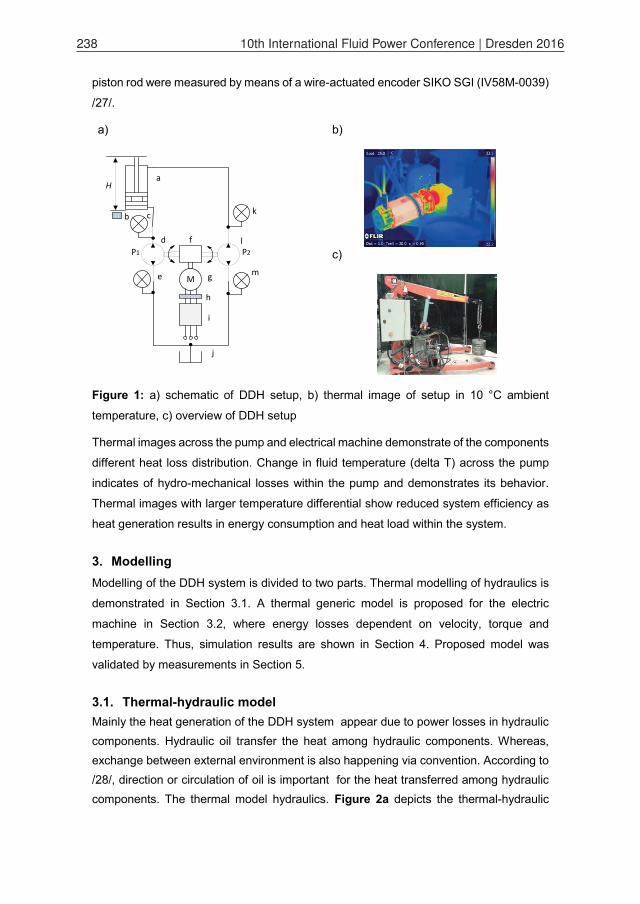
piston rod were measured by means of a wire-actuated encoder SIKO SGI (IV58M-0039)
/27/.
a) b)
M
a
b c
d
e
H
f
g
h
i
j
k
l
m
P2P1
c)
Figure 1: a) schematic of DDH setup, b) thermal image of setup in 10 °C ambient
temperature, c) overview of DDH setup
Thermal images across the pump and electrical machine demonstrate of the components
different heat loss distribution. Change in fluid temperature (delta T) across the pump
indicates of hydro-mechanical losses within the pump and demonstrates its behavior.
Thermal images with larger temperature differential show reduced system efficiency as
heat generation results in energy consumption and heat load within the system.
3. ModellingModelling of the DDH system is divided to two parts. Thermal modelling of hydraulics is
demonstrated in Section 3.1. A thermal generic model is proposed for the electric
machine in Section 3.2, where energy losses dependent on velocity, torque and
temperature. Thus, simulation results are shown in Section 4. Proposed model was
validated by measurements in Section 5.
3.1. Thermal-hydraulic modelMainly the heat generation of the DDH system appear due to power losses in hydraulic components. Hydraulic oil transfer the heat among hydraulic components. Whereas, exchange between external environment is also happening via convention. According to /28/, direction or circulation of oil is important for the heat transferred among hydraulic components. The thermal model hydraulics. Figure 2a depicts the thermal-hydraulic
238 10th International Fluid Power Conference | Dresden 2016
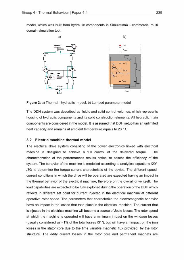
model, which was built from hydraulic components in SimulationX - commercial multi domain simulation tool.
a) b)
Figure 2: a) Thermal - hydraulic model, b) Lumped parameter model
The DDH system was described as fluidic and solid control volumes, which represents
housing of hydraulic components and its solid construction elements. All hydraulic main
components are considered in the model. It is assumed that DDH setup has an unlimited
heat capacity and remains at ambient temperature equals to 23 ° C.
3.2. Electric machine thermal modelThe electrical drive system consisting of the power electronics linked with electrical
machine is designed to achieve a full control of the delivered torque. The
characterization of the performances results critical to assess the efficiency of the
system. The behavior of the machine is modelled according to analytical equations /29/-
/30/ to determine the torque-current characteristic of the device. The different speed-
current conditions in which the drive will be operated are expected having an impact in
the thermal behavior of the electrical machine, therefore on the overall drive itself. The
load capabilities are expected to be fully exploited during the operation of the DDH which
reflects in different set point for current injected in the electrical machine at different
operative rotor speed. The parameters that characterize the electromagnetic behavior
have an impact in the losses that take place in the electrical machine. The current that
is injected in the electrical machine will become a source of Joule losses. The rotor speed
at which the machine is operated will have a minimum impact on the windage losses
(usually considered as <1% of the total losses /31/), but will have an impact on the iron
losses in the stator core due to the time variable magnetic flux provided by the rotor
structure. The eddy current losses in the rotor core and permanent magnets are
Group 4 - Thermal Behaviour | Paper 4-4 239
neglected. The thermal model proposed is designed to evaluate the temperature
distribution within the electrical machine structure according to the heat sources that are
here considered and dependent on the operative condition of the DDH. The temperature
prediction in electrical machine has been a topic highly investigated by many industrial
and academic research centers and different techniques has been proposed. Finite
Element Methods results as the most accurate technique with the drawbacks of high
computational time and time consuming for setting it up; first-second-third order
equivalent circuit methods are considered when fast computation is required and are still
capable of high accuracy prediction /32/-/33/. Hybrid-mid-complex techniques have been
developed to compromise the computational effort and the accuracy of the prediction
/34/. The equivalent resistance network /33/ has been selected as the modelling tool
which better fit the needs of the thermal estimation for the DDH. The proposed model is
based on the assumption of symmetrical supply for the electrical machine and the
exploitation of the geometrical symmetries of the structure allows reducing the model to
a single stator slot. The Fourier equation has been considered discretized for each
macro-part in which the computational domain is divided and equivalent thermal
resistance and capacitance are defined according to the material thermal properties. The
overall result is a linear thermal network which can be solved by means numerical
techniques to evaluate the temperature distribution in the nodes. The inputs of the model
are the heat losses as previously described: joule losses in the copper winding, heat
losses correspondent to the stator iron losses. Boundary conditions have been defined
according to the external condition. The cooling media considered in air and natural
convection is considered between the stator housing and the environment. The
convection coefficient has been defined according to /31/-/32/ and the ambient
temperature has been changed to replicate the test condition in the controlled thermal
chamber. Figure 2b illustrates lumped parameter model. The permanent magnet
brushless servo-motor 115U2C is characterized by = 1.6 and =
9.8 10 , with a rated torque of = 8.1 with an operative maximum speed
of = 3000 . The control system is designed to fulfill the dynamics requirements
of the DDH. The current injected is controlled up to = 23.5 . Steady state and
transitory operative conditions are considered to validate the thermal model of the
machine. The rated current considered defines the value of the heat source in the part
of the lumped parameters that models the copper region. The variation of the resistivity
with respect the temperature is taken into account according to (1)
( ) = (1 + [T 20]), [ ] (1)
240 10th International Fluid Power Conference | Dresden 2016
where is the resistivity of the copper at = , is the thermal coefficient of
the copper and is the operative temperature of the material. The joule losses are
defined by means (2)
= ( )
, [ ] (2)
where is the end region correction factor, _ is the number of phases, is
the number of turn/phase, is the axial length of the machine, the cross section of the
conductors. The iron losses are estimated according to the Steinmetz equation (3)
= + ( ) , [ ] (3)
where is the frequency of the magnetic flux density, is the peak of the magnetic flux
density and , , and are constant coefficient listed in Table 1. The thermal
resistances are defined as (4) and connect the macro-sections in which the
computational domain is divided.
Table 1: Iron Losses coefficients
=
, (4)
= , (5)
where is the conduction coefficient of the material, is the convection coefficient, is
the surface of heat exchange and is the axial length /35/. The thermal convective
equivalent resistance between the electrical machine and the environment is defined as
(5) where the definition of the thermal convection coefficient can be found in /31/. The
number of nodes has been chose as a compromise between the accuracy of the
prediction and the computational effort required. The thermal capacity of the iron and
copper region has been modelled to account for the thermal transitory behavior of the
machine.
4. Simulations ResultsThe thermal model has been tested in ambient operative conditions. The operative
behavior of the DDH is considered to be oscillatory. The rotational speed of the electrical
machine is controlled in order to achieve a periodic change in pressure required as an
output. The amplitude of the current supplied to the machine is defined by means the
Parameter Value0.039
01
1.6886
Group 4 - Thermal Behaviour | Paper 4-4 241
speed loop, featuring peaks when change in directions occurs while only small quantities
are required when the speed in kept constant. The torque generated results directly
proportional with respect the q-axis current which is approximated with its first harmonic
with respect the period of the hydraulic oscillation considered and expressed in (6). The
joule losses are generated by means the square of the current resulting in
( ) = cos( + ) ( ) = cos ( + ) =2
, (6)
where I is the maximum rms value achieved by the current, is the angular speed of
the hydraulic oscillation and its phase angle. The constant equivalent rms current is
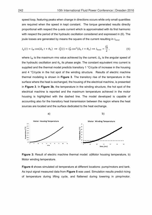
supplied and the thermal model predicts transitory 1 °C/cycle of increase in the housing
and 4 °C/cycle in the hot spot of the winding structure. Results of electric machine
thermal modeling is shown in Figure 3. The transitory rise of the temperature in the
surface where the heat is exchanged, the housing of the electrical machine, is presented
in Figure 3. In Figure 3b, the temperature in the winding structure, the hot spot of the
electrical machine is reported and the maximum temperature achieved in the motor
housing is highlighted with the dashed line. The model developed is capable of
accounting also for the transitory heat transmission between the region where the heat
sources are located and the surface dedicated to the heat exchange.
a) b)
Figure 3: Result of electric machine thermal model: a)Motor housing temperature, b)
Motor winding temperature.
Figure 4 shows simulated oil temperature at different locations: pump/motors and tank.
As input signal measured data from Figure 5 was used. Simulation results predict ricing
of temperature during lifting cycle, and flattened during lowering in pimp/motor.
242 10th International Fluid Power Conference | Dresden 2016
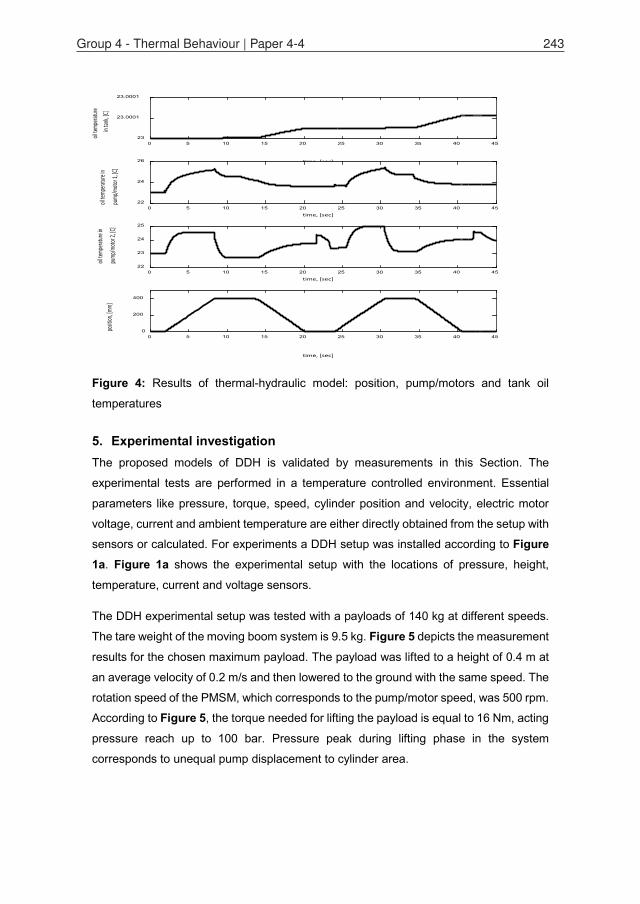
Figure 4: Results of thermal-hydraulic model: position, pump/motors and tank oil
temperatures
5. Experimental investigationThe proposed models of DDH is validated by measurements in this Section. The
experimental tests are performed in a temperature controlled environment. Essential
parameters like pressure, torque, speed, cylinder position and velocity, electric motor
voltage, current and ambient temperature are either directly obtained from the setup with
sensors or calculated. For experiments a DDH setup was installed according to Figure 1a. Figure 1a shows the experimental setup with the locations of pressure, height,
temperature, current and voltage sensors.
The DDH experimental setup was tested with a payloads of 140 kg at different speeds.
The tare weight of the moving boom system is 9.5 kg. Figure 5 depicts the measurement
results for the chosen maximum payload. The payload was lifted to a height of 0.4 m at
an average velocity of 0.2 m/s and then lowered to the ground with the same speed. The
rotation speed of the PMSM, which corresponds to the pump/motor speed, was 500 rpm.
According to Figure 5, the torque needed for lifting the payload is equal to 16 Nm, acting
pressure reach up to 100 bar. Pressure peak during lifting phase in the system
corresponds to unequal pump displacement to cylinder area.
time, [sec]
0 5 10 15 20 25 30 35 40 45
oil te
mpera
ture
in ta
nk, [C
]
23
23.0001
23.0001
time [sec]t
time, [sec]0 5 10 15 20 25 30 35 40 45
oil te
mpera
ture in
pump
/moto
r 1, [C
]
22
24
26
time, [sec]0 5 10 15 20 25 30 35 40 45
oil te
mpera
ture in
pump
/moto
r 2, [C
]
22
23
24
25
time, [sec]
0 5 10 15 20 25 30 35 40 45
positi
on, [m
m]
0
200
400
Group 4 - Thermal Behaviour | Paper 4-4 243
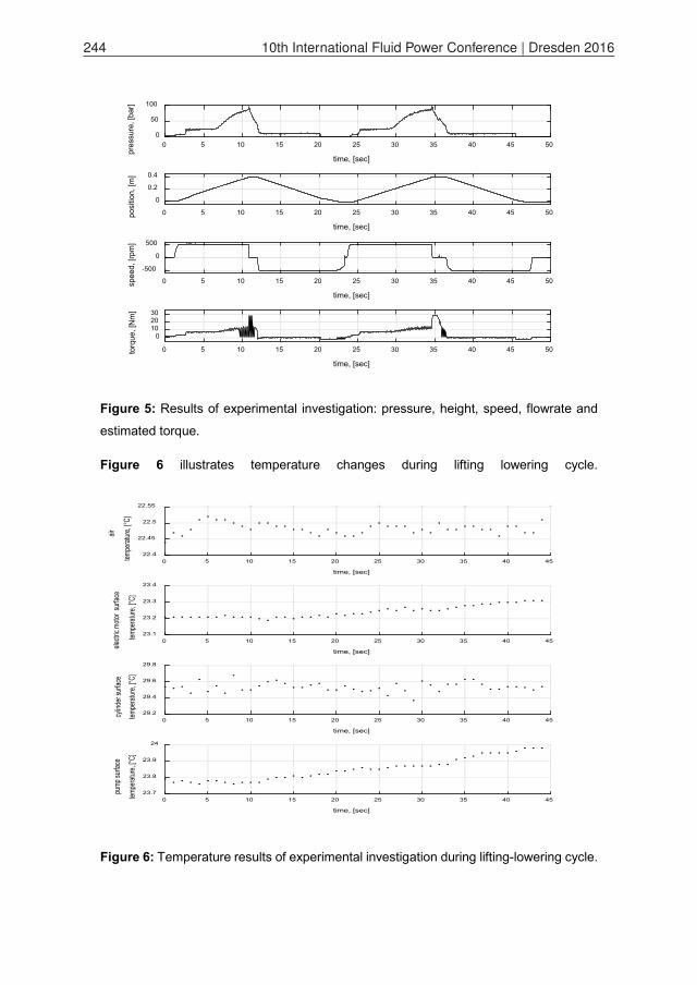
Figure 5: Results of experimental investigation: pressure, height, speed, flowrate and
estimated torque.
Figure 6 illustrates temperature changes during lifting lowering cycle.
Figure 6: Temperature results of experimental investigation during lifting-lowering cycle.
time, [sec]
0 5 10 15 20 25 30 35 40 45 50
pres
sure
, [ba
r]0
50
100
time, [sec]
0 5 10 15 20 25 30 35 40 45 50posi
tion,
[m]
0
0.2
0.4
time, [sec]
0 5 10 15 20 25 30 35 40 45 50spee
d, [r
pm]
-500
0
500
time, [sec]
0 5 10 15 20 25 30 35 40 45 50torq
ue, [
Nm
]
0102030
time, [sec]
0 5 10 15 20 25 30 35 40 45
air
tempe
rature
, [°C]
22.4
22.45
22.5
22.55
time, [sec]
0 5 10 15 20 25 30 35 40 45
electr
ic mo
tor s
urfac
e
temp
eratur
e, [°C
]
23.1
23.2
23.3
23.4
time, [sec]
0 5 10 15 20 25 30 35 40 45
cylin
der s
urfac
e
temp
eratur
e, [°C
]
29.2
29.4
29.6
29.8
time, [sec]
0 5 10 15 20 25 30 35 40 45
pump
surfa
ce
tempe
rature
, [°C]
23.7
23.8
23.9
24
244 10th International Fluid Power Conference | Dresden 2016
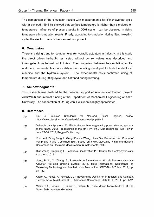
The comparison of the simulation results with measurements for lifting/lowering cycle
with a payload 149.5 kg showed that surface temperature is higher than simulated oil
temperature. Influence of pressure peaks in DDH system can be observed in rising
temperature in simulation results. Finally, according to simulation during lifting-lowering
cycle, the electric motor is the warmest component.
6. ConclusionThere is a rising trend for compact electro-hydraulic actuators in industry. In this study
the direct driven hydraulic test setup without control valves was described and
investigated from thermal point of view. The comparison between the simulation results
and the experimental test data validate the modelling developed for both the electrical
machine and the hydraulic system. The experimental tests confirmed ricing of
temperature during lifting cycle, and flattened during lowering.
7. AcknowledgmentsThis research was enabled by the financial support of Academy of Finland (project
ArcticWell) and internal funding at the Department of Mechanical Engineering at Aalto
University. The cooperation of Dr.-Ing Jani Heikkinen is highly appreciated.
8. References
/1/ Tier 4 Emission Standards for Nonroad Diesel Engines, online, https://www.dieselnet.com/standards/us/nonroad.php#tier4
/2/ Daher, N., Ivantysynova, M., Electro-hydraulic energy-saving power steering systems of the future. 2012. Proceedings of the 7th FPNI PhD Symposium on Fluid Power, June 27-30, 2012, Reggio Emilia, Italy.
/3/ Youzhe Ji, Song Peng, Li Geng, Zhanlin Wang, Lihua Qiu, Pressure Loop Control of Pump and Valve Combined EHA Based on FFIM. 2009.The Ninth International Conference on Electronic Measurement & Instruments, 2009.
/4/ Qian Zhang, Bingqiang Li, Feedback Linearization PID Control for Electro-hydrostatic Actuators, 2011.
/5/ Liang, B., Li, Y., Zhang, Z., Research on Simulation of Aircraft Electro-Hydrostatic Actuator Anti-Skid Braking System. 2011. Third International Conference on Measuring Technology and Mechatronics Automation (ICMTMA), 6-7 Jan. 2011, pp. 78 – 82
/6/ Altare, G., Vacca, A., Richter, C., A Novel Pump Design for an Efficient and Compact Electro-Hydraulic Actuator, IEEE Aerospace Conference, 2014 IEEE, 2014 , pp. 1-12.
/7/ Minav, T.A., Bonato, C., Sainio, P., Pietola, M., Direct driven hydraulic drive, at IFK, March 2014, Aachen, Germany.
Group 4 - Thermal Behaviour | Paper 4-4 245
/8/ Minav, T.A., Bonato, C., Sainio, P., Pietola, M., Efficiency of Direct Driven Hydraulic Drive for Non-road Mobile Working Machines, at ICEM, September 2014, Berlin, Germany.
/9/ Hydraulic_Fluids, http://www.statoil-ellas.lv/files/Hydraulic_Fluids.pdf
/10/ Arctic Low Pour Hydraulic Oil, http://www.phillips66lubricants.com/documents/
/11/ Qinghui Zhou, et.al, Development of Control Strategy for SI Engine Cold Start, IEEE International Conference on Information and Automation June 20 - 23, Harbin, China
/12/ Waleed Nessim, Fujun Zhang, Powertrain Warm-up Improvement using Thermal Management Systems, International Journal of Scientific & Technology Research Volume 1, Issue 4, MAY 2012
/13/ Kauranen P., et.al. Temperature optimisation of a diesel engine using exhaust gas heat recovery and thermal energy storage, http://www.vtt.fi/inf/julkaisut/muut/2010/PCMAkku_ATE2009_Submitted.pdf
/14/ Busquets E., Ivantysynova M., Temperature Prediction of Displacement controlled multi-actuator machines, Int. J. of Fluid Power, Jan., 2014;
/15/ Busquets E., An investigation of the cooling power requirements for displacement-controlled multi-actuator machines, 2013
/16/ Michel S., et.al. Energy-efficiency and thermo energetic behavior of electrohydraulic compact drives, 9th IFK conf. 2014
/17/ Minav,T., P. Sainio, M. Pietola, Efficiency of Direct driven hydraulic setup in arctic conditions, SICFP 2015, May 2015, Tampere, Finland.
/18/ Soudunsaari R.,Hydrauliöljy ja Hydraulipumppu arktissa olosuhteissa , Espoo : VTT, 1985
/19/ Rovellini, et.al. Induction motors for use in arctic environments, PCIC Europe 2010 Conf. proceedings.
/20/ Li Y., et.al. Thermal-hydraulic modeling and simulation of high power hydro-motor, 2008, Asia simulation conference proceedings.
/21/ Tomioka K., et.al., A Method predicting temperature rise of oil-hydraulic system considering heat balance between oil-passage and housing, Int. Conference on Integrated Modelling and analysis in applied control and automation, 2012
/22/ Tomioka ,K.,et.al., Precise and Practical 1D Analysis Method of Temperature in an oil-hydraulic cylinder chamber considering 3D internal flow, Transaction of the japan fluid power system society, Vol.43, N2,2012
/23/ Vivoil motor, Data Sheet: reversible motor - series XV, [Online]. Available: http://www.vivoil.com/files/xm_en/xm201.pdf, visited on September 8, 2013
/24/ Emerson Control Techniques Unimotor 115U 2C, http://www.emersonindustrial.com/en/en/documentcenter/ControlTechniques/Brochures/unimotor_fm_product_data.pdf, visited on September, 2013.
246 10th International Fluid Power Conference | Dresden 2016
/25/ Emerson Control Techniques Unidrive SP1406 drive, http://www.emersonindustrial.com, visited on September 8, 2013.
/26/ Gemssensors 3100R0400S pressure transducers, http://www.gemssensors.com/Products/Pressure/Pressure-Tranducers , visited on September, 2013.
/27/ SIKO SGI (IV58M-0039), http://www.siko-global.com/en-de , visited on October, 2013.
/28/ Kai Li, Zhong Lv, Kun Lu, Ping Yu, Thermal-hydraulic modeling and simulation of the hydraulic su=ystem based on the electro-hydraulic actuator, procedia Engineering 80 (2014) 272-281
/29/ Bolognesi, P., A mid-complexity analysis of long-drum-type electric machines suitable for circuital modeling, ICEM 2008, pp.1-5, 6-9 Sept. 2008doi: 10.1109/ICELMACH.2008.4799879
/30/ Rodríguez, A.L.; Gómez, D.J.; Villar, I.; López-de-Heredia, A.; Etxeberria-Otadui, I., Improved analytical multiphysical modeling of a surface PMSM, 2014 International Conference on Electrical Machines (ICEM), pp.1224-1230, 2-5 Sept. 2014, doi: 10.1109/ICELMACH.2014.6960338
/31/ Howey, D.A.; Childs, P.R.N.; Holmes, A.S., Air-Gap Convection in Rotating Electrical Machines, IEEE Transactions on Industrial Electronics, vol.59, no.3, pp.1367-1375, March 2012, doi: 10.1109/TIE.2010.2100337
/32/ Zhe Huang; Marquez-Fernandez, F.J.; Loayza, Y.; Reinap, A.; Alakula, M., Dynamic thermal modeling and application of electrical machine in hybrid drives, 2014 International Conference on Electrical Machines (ICEM), pp.2158-2164, 2-5 Sept. 2014, doi: 10.1109/ICELMACH.2014.6960483
/33/ Bracikowski, N.; Hecquet, M.; Brochet, P.; Shirinskii, S.V., Multiphysics Modeling of a Permanent Magnet Synchronous Machine by Using Lumped Models, IEEE Transactions on Industrial Electronics, vol.59, no.6, pp.2426-2437, June 2012,doi: 10.1109/TIE.2011.2169640
/34/ Papini, L.; Gerada, C., Thermal-electromagnetic analysis of solid rotor induction machine, 7th IET International Conference on in Power Electronics, Machines and Drives (PEMD 2014),April 2014, doi: 10.1049/cp.2014.0462
/35/ Boglietti, A.; Carpaneto, E.; Cossale, M.; Lucco Borlera, A., Stator thermal model forshort-time thermal transients, 2014 International Conference on in Electrical Machines (ICEM),2-5 Sept. 2014, doi: 10.1109/ICELMACH.2014.6960367
9. Nomenclaturepeak of the magnetic flux density
conduction coefficient of the material
frequency of the magnetic flux density
Group 4 - Thermal Behaviour | Paper 4-4 247
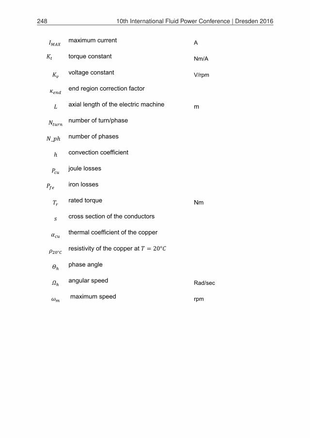
maximum current A
torque constant Nm/A
voltage constant V/rpm
end region correction factor
axial length of the electric machine m
number of turn/phase
_ number of phases
convection coefficient
joule losses
iron losses
rated torque Nm
cross section of the conductors
thermal coefficient of the copper
resistivity of the copper at =
phase angle
angular speed Rad/sec
maximum speed rpm
248 10th International Fluid Power Conference | Dresden 2016