Embed Size (px)
Citation preview
4 210 855 / 00 - 02/13
UltraOil® (320D, 400D, 500D, 600D)Oil condensing double boiler
Hoval products must be installed and commissioned only by appropriately qualified experts. These instruc-tions are intended exclusively for the specialist. Elec-trical installations may only be carried out by a qualified electrician.
The floor standing oil condensing boiler UltraOil® (320D-400D) are designed and approved for use as heat gen-erators for hot water heating systems with a permissible flow temperature of up to 90 ºC1), in accordance with EN 483 and EN 677. They are designed for continuously adjustable reduced output operation in heating systems.1) see section technical data
These instructions apply to the following models:30-UltraOil® (320D) 118 - 320 kW30-UltraOil® (400D) 155 - 400 kW30-UltraOil® (500D) 188 - 500 kW30-UltraOil® (600D) 227 - 600 kW
Subject to modifi cations | EN
Technical informationInstallation instructions
4 210 855 / 00 - 03/13
2 4 210 855 / 00
1. Safety instructions1.1 Key to symbols used ...........................................................................................................................................................3
2. Assembly2.1 Procedure way .....................................................................................................................................................................3
3. Technical Information3.1 Dimensions ..........................................................................................................................................................................43.2 Space requirements ............................................................................................................................................................53.3 Technical data UltraOil® (320D-600D) ..................................................................................................................................6
4. Installation4.3 Flue gas line dimensions (overpressure) ...........................................................................................................................84.4 Flue gas line dimensions (negative pressure) ...................................................................................................................84.5 Hydraulic connection ..........................................................................................................................................................94.6 Boiler sequential switching circuit / Electrical connections / Parameters .......................................................................94.6.1 Schematic coordination .....................................................................................................................................................94.6.2 Application without main pump (system KA100) ..............................................................................................................104.6.3 Application with main pump (system KA090) ...................................................................................................................144.6.4 Legend ...........................................................................................................................................................................18
TABlE OF cOnTEnTS
34 210 855 / 00
Dear CustomerThese instructions concerning our oil condensing boilers UltraOil® (320D-400D) represent additional information on the construction and commissioning of the twin boiler system..
Please see the attached instructions for basic information on technical details, commissioning, servicing and operating:
• Technical Information Installation inst-ructions
• Operating instructions
It is imperative for the boiler commissio-ning to be carried out by a Hoval service engineer or a trained Hoval partner.
1. Safety instructions
i Maximum overpressure in the common fluegasline60Pa
1.1 Key to symbols used
Tools:Shows the tools required for the following work.Instruction:Prompts you to carry out an action.Result:Shows the expected reaction to your action.
i Note:Provides important information.Safety information:Indicates an immediate hazard to persons.Warning information:Indicates danger to machines and installa-tions.
§ Reference to standards and regulations.
2. Assembly2.1 Procedure way1. Prior to placing the boiler in position it must be ther-
mally insulated and clad as far the plinth panels in accordance with the UltraOil® installation instructions.
2. The UltraOil® twin boilers are installed side by side according to the dimensional drawings below. (The hydraulic connection lines are optional).
2a. Mounting of the plinth panels and the optional con-densate box according to UltraOil® installation instruc-tions.
3. See separate instructions for the mounting of the flue gas overpressure set!
4. Optional:Mounting of the hydraulic pipeline connection set (common flow and return).
i See the instructions for the hydraulic connection set.
ASSEmBly
4 4 210 855 / 00
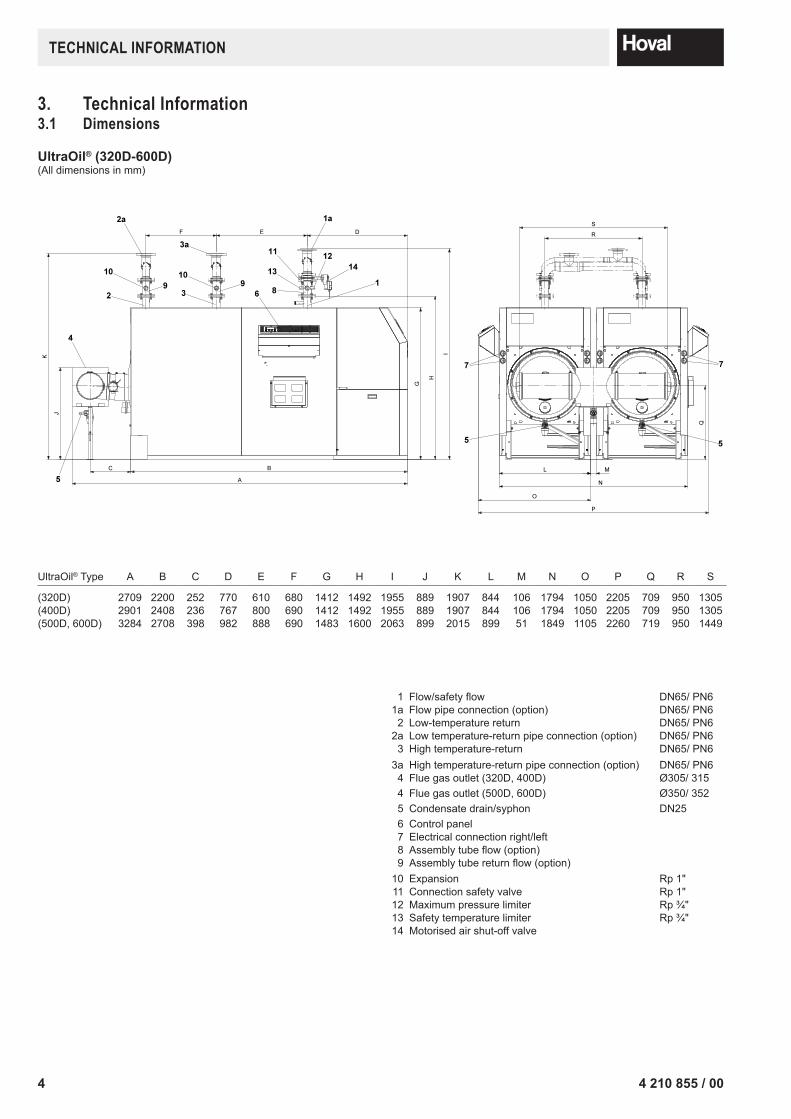
3. Technical Information3.1 Dimensions
UltraOil®(320D-600D)(All dimensions in mm)
1 Flow/safety flow DN65/ PN61a Flow pipe connection (option) DN65/ PN6
2 Low-temperature return DN65/ PN62a Low temperature-return pipe connection (option) DN65/ PN6
3 High temperature-return DN65/ PN63a High temperature-return pipe connection (option) DN65/ PN6
4 Flue gas outlet (320D, 400D) Ø305/ 3154 Flue gas outlet (500D, 600D) Ø350/ 3525 Condensate drain/syphon DN256 Control panel7 Electrical connection right/left8 Assembly tube flow (option)9 Assembly tube return flow (option)
10 Expansion Rp 1"11 Connection safety valve Rp 1"12 Maximum pressure limiter Rp ¾"13 Safety temperature limiter Rp ¾"14 Motorised air shut-off valve
UltraOil® Type A B C D E F G H I J K L M N O P Q R S
(320D) 2709 2200 252 770 610 680 1412 1492 1955 889 1907 844 106 1794 1050 2205 709 950 1305(400D) 2901 2408 236 767 800 690 1412 1492 1955 889 1907 844 106 1794 1050 2205 709 950 1305(500D, 600D) 3284 2708 398 982 888 690 1483 1600 2063 899 2015 899 51 1849 1105 2260 719 950 1449
TEcHnIcAl InFOrmATIOn
54 210 855 / 00
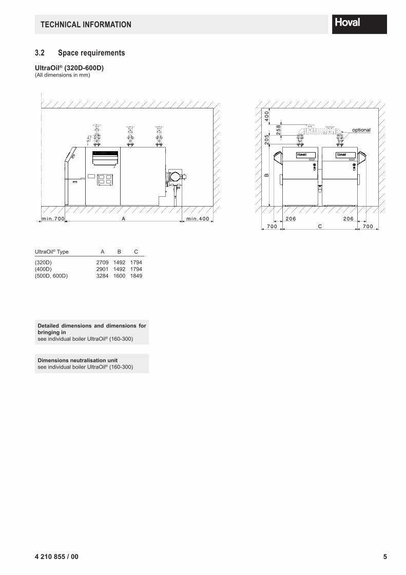
3.2 Space requirements
UltraOil®(320D-600D)(All dimensions in mm)
UltraOil® Type A B C
(320D) 2709 1492 1794(400D) 2901 1492 1794(500D, 600D) 3284 1600 1849
Detailed dimensions and dimensions for bringing insee individual boiler UltraOil® (160-300)
Dimensions neutralisation unit see individual boiler UltraOil® (160-300)
TEcHnIcAl InFOrmATIOn
6 4 210 855 / 00
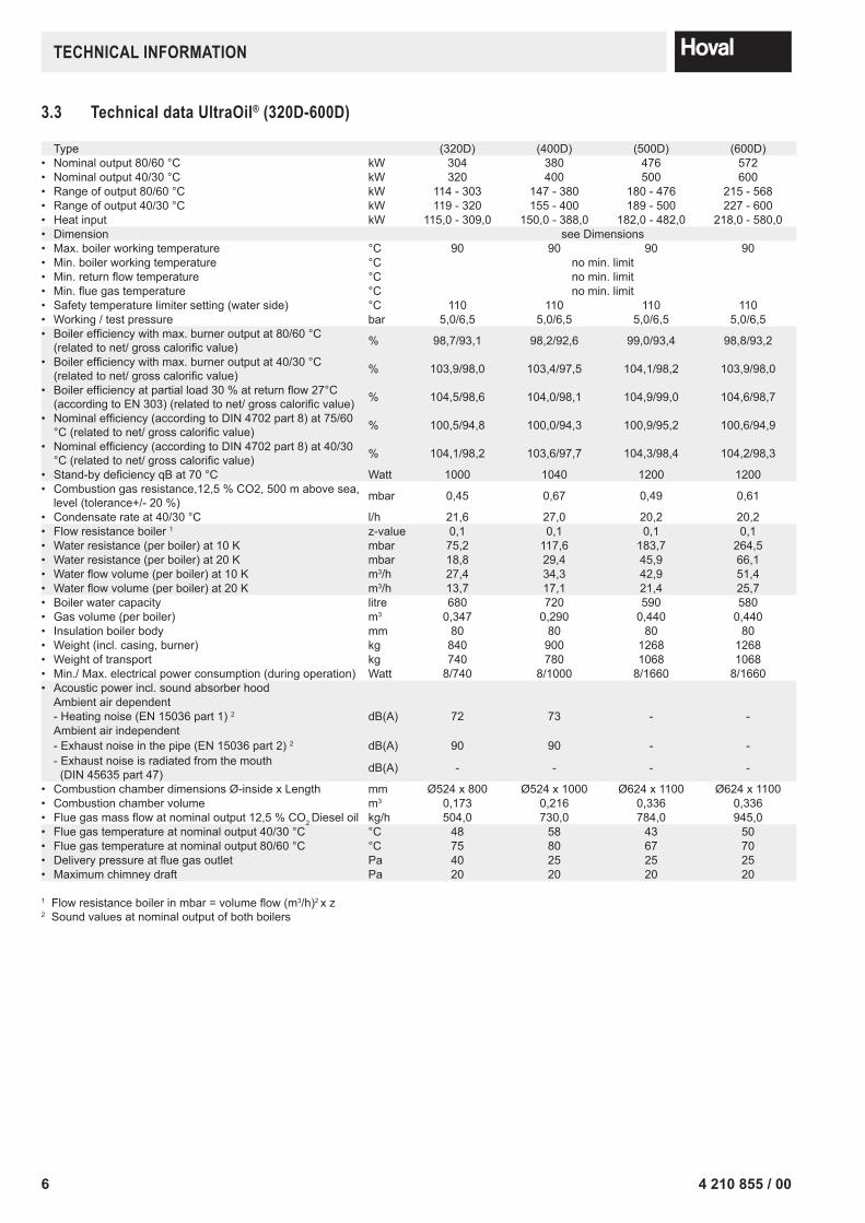
3.3 Technical data UltraOil® (320D-600D)
Type (320D) (400D) (500D) (600D)• Nominal output 80/60 °C kW 304 380 476 572• Nominal output 40/30 °C kW 320 400 500 600• Range of output 80/60 °C kW 114 - 303 147 - 380 180 - 476 215 - 568• Range of output 40/30 °C kW 119 - 320 155 - 400 189 - 500 227 - 600• Heat input kW 115,0 - 309,0 150,0 - 388,0 182,0 - 482,0 218,0 - 580,0• Dimension see Dimensions• Max. boiler working temperature °C 90 90 90 90• Min. boiler working temperature °C no min. limit• Min. return flow temperature °C no min. limit• Min. flue gas temperature °C no min. limit• Safety temperature limiter setting (water side) °C 110 110 110 110• Working / test pressure bar 5,0/6,5 5,0/6,5 5,0/6,5 5,0/6,5• Boiler efficiency with max. burner output at 80/60 °C
(related to net/ gross calorific value) % 98,7/93,1 98,2/92,6 99,0/93,4 98,8/93,2
• Boiler efficiency with max. burner output at 40/30 °C(related to net/ gross calorific value) % 103,9/98,0 103,4/97,5 104,1/98,2 103,9/98,0
• Boiler efficiency at partial load 30 % at return flow 27°C (according to EN 303) (related to net/ gross calorific value) % 104,5/98,6 104,0/98,1 104,9/99,0 104,6/98,7
• Nominal efficiency (according to DIN 4702 part 8) at 75/60 °C (related to net/ gross calorific value) % 100,5/94,8 100,0/94,3 100,9/95,2 100,6/94,9
• Nominal efficiency (according to DIN 4702 part 8) at 40/30 °C (related to net/ gross calorific value) % 104,1/98,2 103,6/97,7 104,3/98,4 104,2/98,3
• Stand-by deficiency qB at 70 °C Watt 1000 1040 1200 1200• Combustion gas resistance,12,5 % CO2, 500 m above sea,
level (tolerance+/- 20 %) mbar 0,45 0,67 0,49 0,61
• Condensate rate at 40/30 °C l/h 21,6 27,0 20,2 20,2• Flow resistance boiler 1 z-value 0,1 0,1 0,1 0,1• Water resistance (per boiler) at 10 K mbar 75,2 117,6 183,7 264,5• Water resistance (per boiler) at 20 K mbar 18,8 29,4 45,9 66,1• Water flow volume (per boiler) at 10 K m3/h 27,4 34,3 42,9 51,4• Water flow volume (per boiler) at 20 K m3/h 13,7 17,1 21,4 25,7• Boiler water capacity litre 680 720 590 580• Gas volume (per boiler) m3 0,347 0,290 0,440 0,440• Insulation boiler body mm 80 80 80 80• Weight (incl. casing, burner) kg 840 900 1268 1268• Weight of transport kg 740 780 1068 1068• Min./ Max. electrical power consumption (during operation) Watt 8/740 8/1000 8/1660 8/1660• Acoustic power incl. sound absorber hood
Ambient air dependent- Heating noise (EN 15036 part 1) 2 dB(A) 72 73 - -Ambient air independent- Exhaust noise in the pipe (EN 15036 part 2) 2 dB(A) 90 90 - -- Exhaust noise is radiated from the mouth (DIN 45635 part 47) dB(A) - - - -
• Combustion chamber dimensions Ø-inside x Length mm Ø524 x 800 Ø524 x 1000 Ø624 x 1100 Ø624 x 1100• Combustion chamber volume m3 0,173 0,216 0,336 0,336• Flue gas mass flow at nominal output 12,5 % CO2 Diesel oil kg/h 504,0 730,0 784,0 945,0• Flue gas temperature at nominal output 40/30 °C °C 48 58 43 50• Flue gas temperature at nominal output 80/60 °C °C 75 80 67 70• Delivery pressure at flue gas outlet Pa 40 25 25 25• Maximum chimney draft Pa 20 20 20 20
1 Flow resistance boiler in mbar = volume flow (m3/h)2 x z2 Sound values at nominal output of both boilers
TEcHnIcAl InFOrmATIOn
74 210 855 / 00
InSTAllATIOn
4. Installation4.1 Boiler room requirementsRegarding the building specifications for boiler rooms and their supply and extract air handling, the current building supervisory office regulations specific to the state or country are to be observed.
Ensure an adequate supply of fresh air to the boiler room to make sure that there is an unobstructed flow of the combustion air required for the operation of all com-bustion devices in the boiler room and so that there is no shortage of oxygen for operating personnel.The binding values for the size of intake air apertures are not usually stated in the relevant regulations, it is laid down only that the partial vacuum in the boiler room must not exceed 3 N/m2.
4.2 Flue gas connection and chimney
Thefluegassystemmustbegastight,wa-tertight, resistant to acids and approved for usewith the corresponding flue gastemperatures of up to 120°C and for over-pressure.
Horizontal connection lines must be rout-ed with a downward slope of at least 50 mm per running metre of their length in the direction of the boiler to ensure that condensate can flow unhindered backto theboiler.Thewholefluegassystemmust be designed to prevent condensate collecting.
The UltraOil®isdeliveredwithafluegassafetytem-peraturelimiter.Forthisreason,noadditionalfluegassafety temperature limiter is required forfluegassystemswithamax.permissiblefluegastem-perature of 120°.
As a result of the water vapour in the flue gas and the low flue gas temperature, condensate forms in the chimney. This means that oil condensing boilers cannot be connected to conventional domestic chimneys.
The valid official stipulations and regulations with regard to flue gas evacuation must be observed.
There are two possible ways to evacuate flue gas from oil condensing boilers:
a) the use of special flue gas conduits approved by the building authorities,
b) the use of moisture-resistant chimneys which are appro-ved for flue gas temperatures of over 40 °C, connected to the oil condensing boiler in the boiler installation room by means of approved flue gas conduits.
In both cases, the cross-sections and maximum lengths must be calculated on the basis of the flue gas mass flow, flue gas temperature and available maximum delivery pressure at the flue gas outlet in accordance with the table in section 4.2 (EN 13384).
8 4 210 855 / 00
InSTAllATIOn
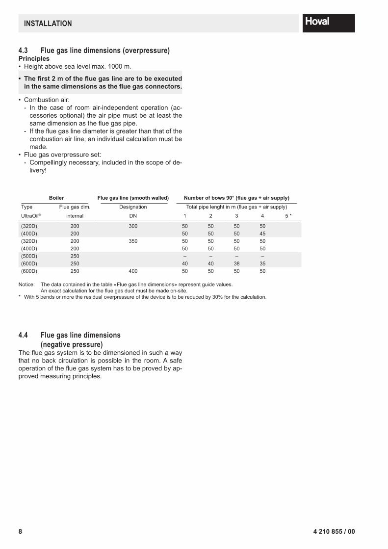
4.3 Flue gas line dimensions (overpressure)Principles• Height above sea level max. 1000 m.
• Thefirst2mofthefluegaslinearetobeexecutedinthesamedimensionsasthefluegasconnectors.
• Combustion air: - In the case of room air-independent operation (ac-cessories optional) the air pipe must be at least the same dimension as the flue gas pipe.
- If the flue gas line diameter is greater than that of the combustion air line, an individual calculation must be made.
• Flue gas overpressure set: - Compellingly necessary, included in the scope of de-livery!
Boiler Fluegasline(smoothwalled) Numberofbows90°(fluegas+airsupply)Type Flue gas dim. Designation Total pipe lenght in m (flue gas + air supply)
UltraOil® internal DN 1 2 3 4 5 *
(320D) 200 300 50 50 50 50(400D) 200 50 50 50 45(320D) 200 350 50 50 50 50(400D) 200 50 50 50 50(500D) 250 – – – –(600D) 250 40 40 38 35(600D) 250 400 50 50 50 50
Notice: The data contained in the table «Flue gas line dimensions» represent guide values. An exact calculation for the flue gas duct must be made on-site.
* With 5 bends or more the residual overpressure of the device is to be reduced by 30% for the calculation.
4.4 Flue gas line dimensions (negative pressure)
The flue gas system is to be dimensioned in such a way that no back circulation is possible in the room. A safe operation of the flue gas system has to be proved by ap-proved measuring principles.
94 210 855 / 00
InSTAllATIOn
4.5 Hydraulic connection• Ensure that the boilers are in each case connected in
the Tichelmann system.• Please comply with separate installation instructions if
the optional hydraulic set is used.• When using the high temperature-return, install this so
that the connection socket is located on the same size (see chapter 3.1).
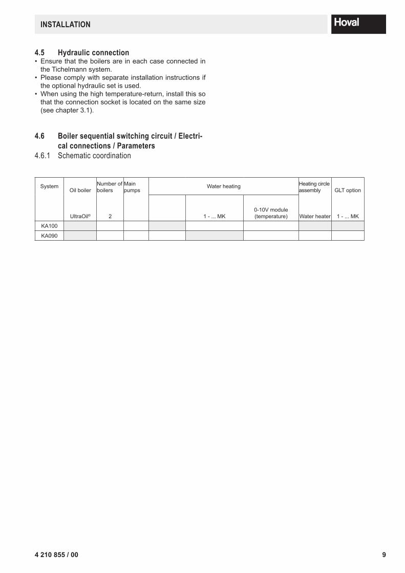
4.6 Boiler sequential switching circuit / Electri-cal connections / Parameters
4.6.1 Schematic coordination
SystemOil boiler
Number of boilers
Main pumps
Water heating Heating circle assembly GLT option
UltraOil® 2 1 - ... MK0-10V module (temperature) Water heater 1 - ... MK
KA100
KA090
10 4 210 855 / 00
InSTAllATIOn
Version
> »Verbindungshinweise /Notice / Nota / Remarque:
.
Datei: KA100.vsd
Datum Name08.03.03Achtung ! Für die Installation muss das anlagenbezogene Schema verwendet werden!KA100.VSD
Attention! This is just a schematic. For installation please use the detail-plan!Attenzione! Per la messa in opera, utilizzare le schema dettagliato!Attention! Pour la réalisation pratique de l'installation, il faut utiliser le schéma détaillé!
.
+ Leg. LK010
1 / 7
Adr.10-VA1
Y10.1
Adr.20-VA1
Y10.2Bezeichnung /Notation /Denominazione /DésignationKlemme /Terminal /Morsetti /Bornes
0-10VModul B1VF1
T T
M K 1
MYK1
B1VF2
T T
M K 2
MYK2
B1VF3
T T
M K 3
MYK3
B1VF2
T T
M K 2
MYK2
T T
M K 2
MYK2
B1VF2 B1VF4
T T
M K 4
MYK4
B1VF4
T T
M K 4
MYK4
AF
TopTronic T TopTronic T
1 1
Y10.1 Y10.2
Dies ist ein unerlaubter Weg!Gehen Sie einen Schritt zurück oder löschen Sie dieses Shape!Sie haben die Möglichkeit ein neues Shape zu nehmen!!! hovhovalhhovalhovaalhovalho
P
UltraOil
Dies ist ein unerlaubter Weg!Gehen Sie einen Schritt zurück oder löschen Sie dieses Shape!Sie haben die Möglichkeit ein neues Shape zu nehmen!!! hovhovalhhovalhovaalhovalho
P
UltraOil
Dies ist ein unerlaubter Weg!Gehen Sie einen Schritt zurück oder löschen Sie dieses Shape!Sie haben die Möglichkeit ein neues Shape zu nehmen!!! hovhovalhovalhovalhovalhovalhovalhovalhovalhovalhovalhovalhovalhovalhovalhovalhovalhovalhovalhovalhovalhovalhovalhovalhovalhovalhovalhovalhovalhovalhovalh
WW
T
KW
S F
S L P
SB-Y4 SB-Y4
Version
E-1 »Verbindungshinweise /Notice / Nota / Remarque:
.
Datei: KA100.vsd
Datum Name08.03.03Achtung ! Für die Installation muss das anlagenbezogene Schema verwendet werden!KA100.VSD
Attention! This is just a schematic. For installation please use the detail-plan!Attenzione! Per la messa in opera, utilizzare le schema dettagliato!Attention! Pour la réalisation pratique de l'installation, il faut utiliser le schéma détaillé!
.
+ Leg. LK010
2 / 7
U3.3/U3.4
2 1VE2
2 1VE3
YK3
PEN
MK3
M1~*
SLP
M1~
N PE 2
L PE NMK 2
N PE 1
L PE NMK 1
L PE NDKP
L PE NSLP
L PE NVA1
L PE NVA2
L PE NNetzSK1
RS-T/RFF-T
BA
1 2SF
1 2VF1
1 2VE1
A BT2B
1 2VF2
1 2KVLF
1 2KSPF
1 2IMP
B5 T6 T7 T8 2
B4 S3 T2 T1 N PE 1
L
SF VF1 VF3
SK2
B2
T
B5
AF
1 2AF
1 2KF
KF Netz 230V~/10A
SH01
L N
K6
N 21 22 23 24
Y6.1
N
25BZ2BZ1SM
16 17
Kessel 1, boiler 1, caldaia 1, chaudière 1
BUS-Verbindung zu Klemmen Kessel 1,2,... , BUS-Connection to terminal block boiler 1,2, ...,BUS-Collegamento a morsettiera pompa di caldaia 1,2,... , BUS-Connexion aux bornes de la chaudière 1,2,...BA
T2B
YK1
PEN
MK1
M1~*
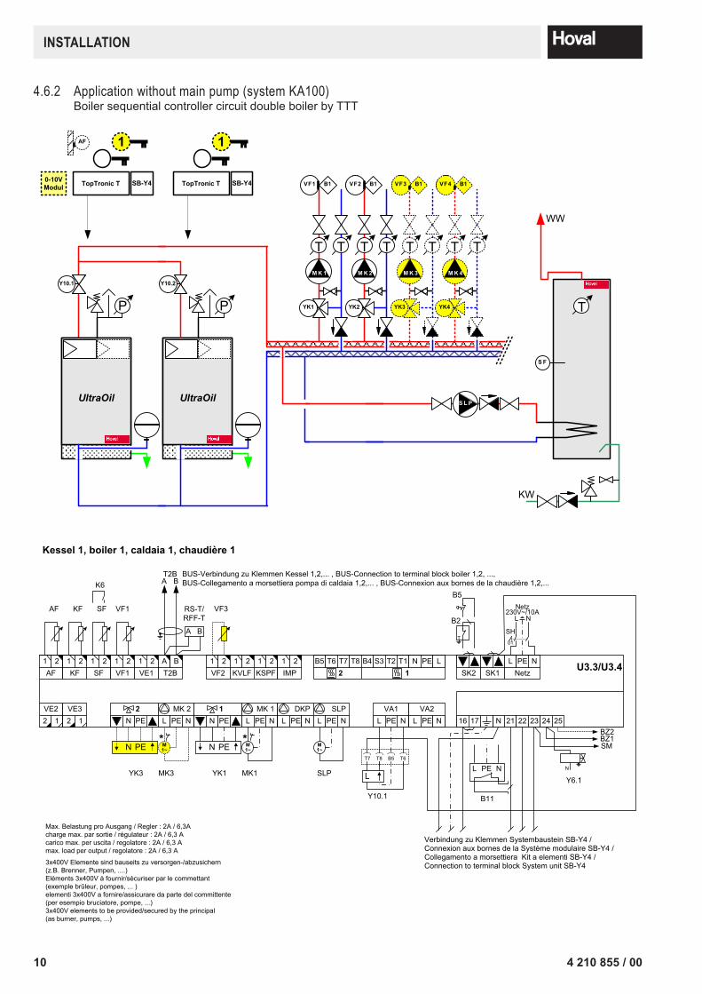
Max. Belastung pro Ausgang / Regler : 2A / 6,3Acharge max. par sortie / régulateur : 2A / 6,3 Acarico max. per uscita / regolatore : 2A / 6,3 Amax. load per output / regolatore : 2A / 6,3 A
3x400V Elemente sind bauseits zu versorgen-/abzusichern (z.B. Brenner, Pumpen, ....)Eléments 3x400V à fournir/sécuriser par le commettant (exemple brûleur, pompes, ... )elementi 3x400V a fornire/assicurare da parte del committente (per esempio bruciatore, pompe, ...)3x400V elements to be provided/secured by the principal (as burner, pumps, ...)
B11
PEL N
Verbindung zu Klemmen Systembaustein SB-Y4 / Connexion aux bornes de la Système modulaire SB-Y4 / Collegamento a morsettiera Kit a elementi SB-Y4 / Connection to terminal block System unit SB-Y4
B5T8T7 T6
Y10.1
L
4.6.2 Application without main pump (system KA100)Boiler sequential controller circuit double boiler by TTT
114 210 855 / 00
InSTAllATIOn
Version
E-2 »Verbindungshinweise /Notice / Nota / Remarque:
.
Datei: KA100.vsd
Datum Name08.03.03Achtung ! Für die Installation muss das anlagenbezogene Schema verwendet werden!KA100.VSD
Attention! This is just a schematic. For installation please use the detail-plan!Attenzione! Per la messa in opera, utilizzare le schema dettagliato!Attention! Pour la réalisation pratique de l'installation, il faut utiliser le schéma détaillé!
.
+ Leg. LK010
3 / 7
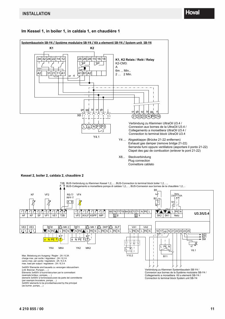
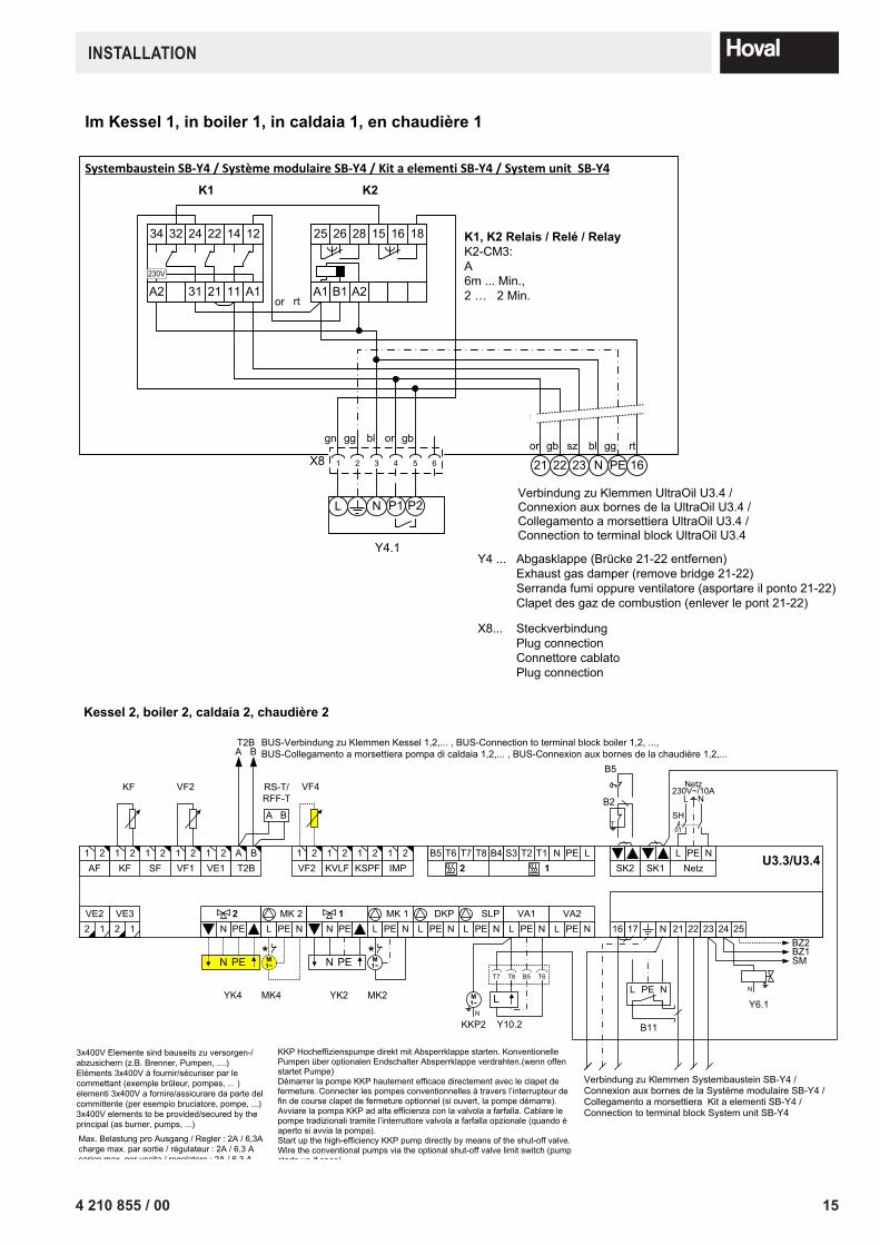
Im Kessel 1, in boiler 1, in caldaia 1, en chaudière 1
Y4 ... Abgasklappe (Brücke 21-22 entfernen)Exhaust gas damper (remove bridge 21-22)Serranda fumi oppure ventilatore (asportare il ponto 21-22)Clapet des gaz de combustion (enlever le pont 21-22)
K1, K2 Relais / Relé / RelayK2-CM3: A6m ... Min.,2 … 2 Min.A1 B1 A2
25 26 28 15 16 18
Verbindung zu Klemmen UltraOil U3.4 / Connexion aux bornes de la UltraOil U3.4 / Collegamento a morsettiera UltraOil U3.4 / Connection to terminal block UltraOil U3.4
PE 16N22 23321 4 5 6
gn gg bl or gb
Y4.1
L
X8or gb bl gg rt
rt
X8... SteckverbindungPlug connectionConnettore cablatoPlug connection
N P2
21sz
or
K1 K2
A2 31230V
34 32 24 22 14 12
21 11 A1
Systembaustein SB-Y4 / Système modulaire SB-Y4 / Kit a elementi SB-Y4 / System unit SB-Y4
P1
Version
E-3 »Verbindungshinweise /Notice / Nota / Remarque:
.
Datei: KA100.vsd
Datum Name08.03.03Achtung ! Für die Installation muss das anlagenbezogene Schema verwendet werden!KA100.VSD
Attention! This is just a schematic. For installation please use the detail-plan!Attenzione! Per la messa in opera, utilizzare le schema dettagliato!Attention! Pour la réalisation pratique de l'installation, il faut utiliser le schéma détaillé!
.
+ Leg. LK010
4 / 7
U3.3/U3.4
2 1VE2
2 1VE3
YK2
PEN
MK2
M1~*
N PE 2
L PE NMK 2
N PE 1
L PE NMK 1
L PE NDKP
L PE NSLP
L PE NVA1
L PE NVA2
L PE NNetzSK1
RS-T/RFF-T
BA
1 2SF
1 2VF1
1 2VE1
A BT2B
1 2VF2
1 2KVLF
1 2KSPF
1 2IMP
B5 T6 T7 T8 2
B4 S3 T2 T1 N PE 1
L
VF2 VF4
SK2
B2
T
B5
1 2AF
1 2KF
KF Netz 230V~/10A
SH01
L N
N 21 22 23 24
Y6.1
N
25BZ2BZ1SM
16 17
Kessel 2, boiler 2, caldaia 2, chaudière 2
BUS-Verbindung zu Klemmen Kessel 1,2,... , BUS-Connection to terminal block boiler 1,2, ...,BUS-Collegamento a morsettiera pompa di caldaia 1,2,... , BUS-Connexion aux bornes de la chaudière 1,2,...BA
T2B
MK4
M1~*
YK4
PEN
Max. Belastung pro Ausgang / Regler : 2A / 6,3Acharge max. par sortie / régulateur : 2A / 6,3 Acarico max. per uscita / regolatore : 2A / 6,3 Amax. load per output / regolatore : 2A / 6,3 A
3x400V Elemente sind bauseits zu versorgen-/abzusichern (z.B. Brenner, Pumpen, ....)Eléments 3x400V à fournir/sécuriser par le commettant (exemple brûleur, pompes, ... )elementi 3x400V a fornire/assicurare da parte del committente (per esempio bruciatore, pompe, ...)3x400V elements to be provided/secured by the principal (as burner, pumps, ...)
B11
PEL N
Verbindung zu Klemmen Systembaustein SB-Y4 / Connexion aux bornes de la Système modulaire SB-Y4 / Collegamento a morsettiera Kit a elementi SB-Y4 / Connection to terminal block System unit SB-Y4
B5T8T7 T6
Y10.2
L
12 4 210 855 / 00
InSTAllATIOn
Version
E-4 »Verbindungshinweise /Notice / Nota / Remarque:
.
Datei: KA100.vsd
Datum Name08.03.03Achtung ! Für die Installation muss das anlagenbezogene Schema verwendet werden!KA100.VSD
Attention! This is just a schematic. For installation please use the detail-plan!Attenzione! Per la messa in opera, utilizzare le schema dettagliato!Attention! Pour la réalisation pratique de l'installation, il faut utiliser le schéma détaillé!
.
+ Leg. LK010
5 / 7
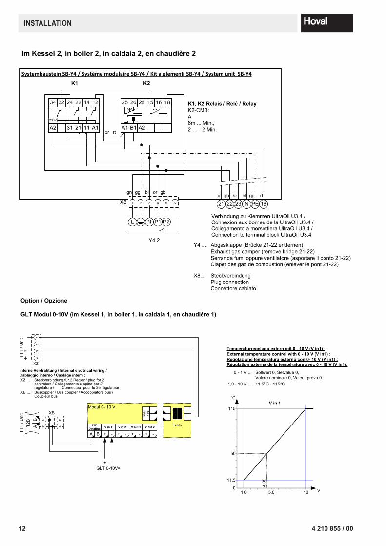
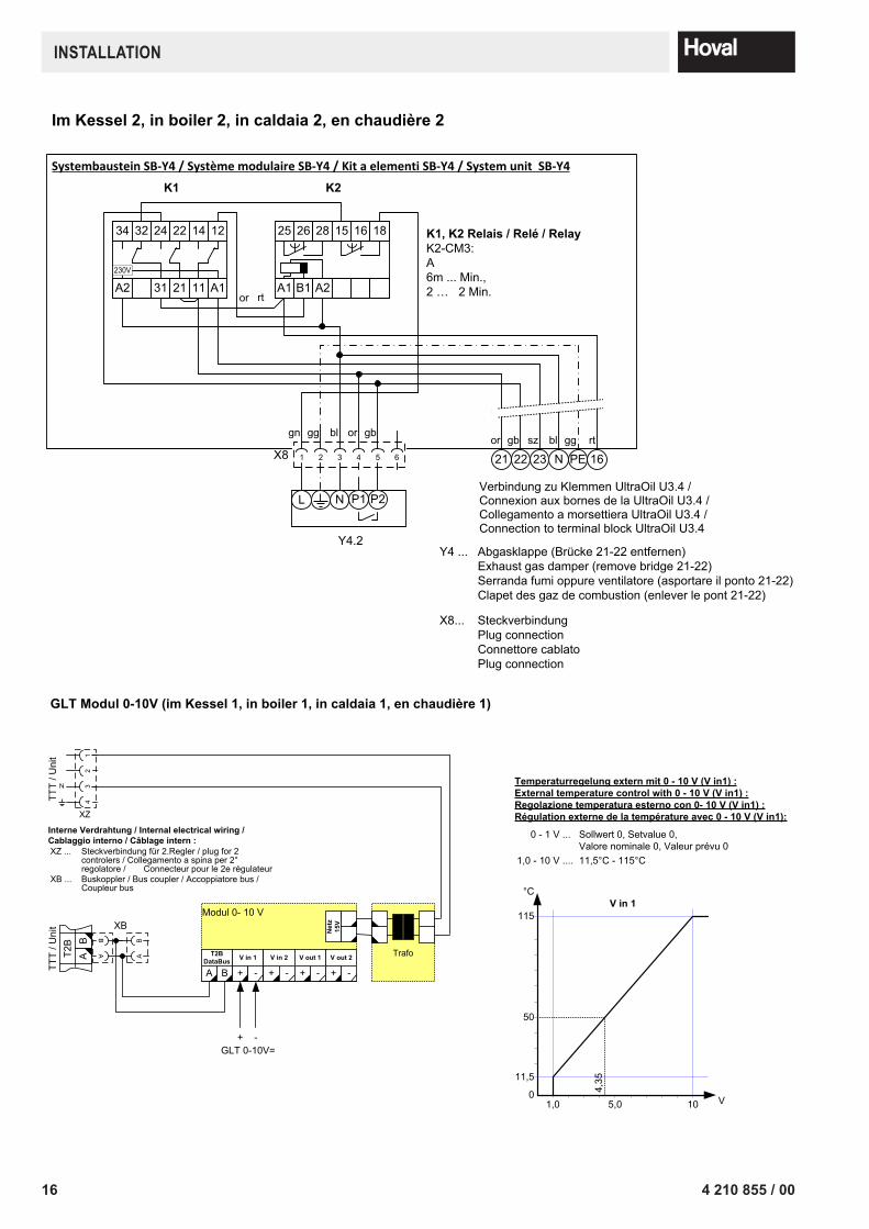
Im Kessel 2, in boiler 2, in caldaia 2, en chaudière 2
Y4 ... Abgasklappe (Brücke 21-22 entfernen)Exhaust gas damper (remove bridge 21-22)Serranda fumi oppure ventilatore (asportare il ponto 21-22)Clapet des gaz de combustion (enlever le pont 21-22)
K1, K2 Relais / Relé / RelayK2-CM3: A6m ... Min.,2 … 2 Min.A1 B1 A2
25 26 28 15 16 18
Verbindung zu Klemmen UltraOil U3.4 / Connexion aux bornes de la UltraOil U3.4 / Collegamento a morsettiera UltraOil U3.4 / Connection to terminal block UltraOil U3.4
PE 16N22 23321 4 5 6
gn gg bl or gb
Y4.2
L
X8or gb bl gg rt
rt
X8... SteckverbindungPlug connectionConnettore cablatoPlug connection
N P2
21sz
or
K1 K2
A2 31230V
34 32 24 22 14 12
21 11 A1
Systembaustein SB-Y4 / Système modulaire SB-Y4 / Kit a elementi SB-Y4 / System unit SB-Y4
P1
Version
E-5 »Verbindungshinweise /Notice / Nota / Remarque:
.
Datei: KA100.vsd
Datum Name08.03.03Achtung ! Für die Installation muss das anlagenbezogene Schema verwendet werden!KA100.VSD
Attention! This is just a schematic. For installation please use the detail-plan!Attenzione! Per la messa in opera, utilizzare le schema dettagliato!Attention! Pour la réalisation pratique de l'installation, il faut utiliser le schéma détaillé!
.
+ Leg. LK010
6 / 7
1,0 10 V
°C
115
11,5
0
50
5,0
4,35
V in 1
Temperaturregelung extern mit 0 - 10 V (V in1) :External temperature control with 0 - 10 V (V in1) :Regolazione temperatura esterno con 0- 10 V (V in1) :Régulation externe de la température avec 0 - 10 V (V in1):
0 - 1 V ... Sollwert 0, Setvalue 0, Valore nominale 0, Valeur prévu 0
1,0 - 10 V .... 11,5°C - 115°C
23
41
N
XZ
Interne Verdrahtung / Internal electrical wiring /Cablaggio interno / Câblage intern :XZ ... Steckverbindung für 2.Regler / plug for 2
controlers / Collegamento a spina per 2° regolatore / Connecteur pour le 2e régulateur
XB ... Buskoppler / Bus coupler / Accoppiatore bus /Coupleur bus
TTT
/ Uni
t
Trafo
A B
T2B DataBus
+ -
V in 1
+ -
V in 2
+ -
V out 1
+ -
V out 2
Net
z 15
V
Modul 0- 10 V
BT2
BA
BA
BA
TTT
/ Uni
t XB
GLT 0-10V=+ -
GLT Modul 0-10V (im Kessel 1, in boiler 1, in caldaia 1, en chaudière 1)
Option / Opzione
134 210 855 / 00
InSTAllATIOn
Version
Par. »Verbindungshinweise /Notice / Nota / Remarque:
.
Datei: KA100.vsd
Datum Name08.03.03Achtung ! Für die Installation muss das anlagenbezogene Schema verwendet werden!KA100.VSD
Attention! This is just a schematic. For installation please use the detail-plan!Attenzione! Per la messa in opera, utilizzare le schema dettagliato!Attention! Pour la réalisation pratique de l'installation, il faut utiliser le schéma détaillé!
.
+ Leg. LK010
7 / 7
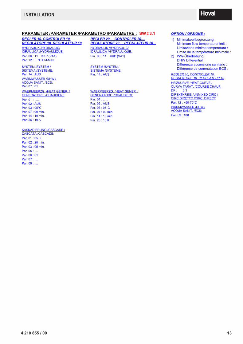
PARAMETER /PARAMETER /PARAMETRO /PARAMETRE :REGLER 10, CONTROLER 10, REGULATORE 10, REGULATEUR 10
REGLER 20..., CONTROLER 20..., REGULATORE 20..., REGULATEUR 20...
SYSTEM /SYSTEM /SISTEMA /SYSTEME:Par. 14 : AUS
SYSTEM /SYSTEM /SISTEMA /SYSTEME:Par. 14 : AUS
WARMWASSER /DHW /ACQUA SANIT. /ECS:Par. 07 : 01
HYDRAULIK /HYDRAULIC/IDRAULICA /HYDRAULIQUE:
HYDRAULIK /HYDRAULIC/IDRAULICA /HYDRAULIQUE:Par. 06 : 11 KKP (VA1)
WAERMEERZG. /HEAT GENER. /GENERATORE /CHAUDIERE Par. 01 : ......
Par. 14 : 10 min.
Par. 03 : 05°C
Par. 26 : 10 K
Par. 07 : 00 min.
WAERMEERZG. /HEAT GENER. /GENERATORE /CHAUDIERE Par. 01 : ......
Par. 14 : 10 min.
Par. 03 : 05°C
Par. 26 : 10 K
Par. 07 : 00 min.
KASKADIERUNG /CASCADE /CASCATA /CASCADE:Par. 01 : 05 K
Par. 03 : 05 min. Par. 02 : 20 min.
Par. 05 : ....Par. 06 : 01Par. 07 : ....Par. 09 : ....
Par. 06 : 11 KKP (VA1)
1) Minimalwertbegrenzung :Minimum flow temperature limit :Limitazione minima temperatura :Limite de la température minimale :
2) WW-Überhöhung :DHW Differential :Differenza accensione sanitario :Différence de commutation ECS :
REGLER 10, CONTROLER 10, REGULATORE 10, REGULATEUR 10HEIZKURVE /HEAT.CURVE /CURVA TARAT. /COURBE CHAUF:DK : 0.3DIREKTKREIS /UNMIXED CIRC / CIRC.DIRETTO /CIRC. DIRECTPar. 12 : ~50-70°CWARMWASSER /DHW /ACQUA SANIT. /ECS:Par. 09 : 10K
OPTION / OPZIONE :
SW 3.1=>
Par. 02 : AUS Par. 02 : AUS
Par. 12 : ... °C EM-Max.
Version
Par. »Verbindungshinweise /Notice / Nota / Remarque:
.
Datei: KA100.vsd
Datum Name08.03.03Achtung ! Für die Installation muss das anlagenbezogene Schema verwendet werden!KA100.VSD
Attention! This is just a schematic. For installation please use the detail-plan!Attenzione! Per la messa in opera, utilizzare le schema dettagliato!Attention! Pour la réalisation pratique de l'installation, il faut utiliser le schéma détaillé!
.
+ Leg. LK010
7 / 7
PARAMETER /PARAMETER /PARAMETRO /PARAMETRE :REGLER 10, CONTROLER 10, REGULATORE 10, REGULATEUR 10
REGLER 20..., CONTROLER 20..., REGULATORE 20..., REGULATEUR 20...
SYSTEM /SYSTEM /SISTEMA /SYSTEME:Par. 14 : AUS
SYSTEM /SYSTEM /SISTEMA /SYSTEME:Par. 14 : AUS
WARMWASSER /DHW /ACQUA SANIT. /ECS:Par. 07 : 01
HYDRAULIK /HYDRAULIC/IDRAULICA /HYDRAULIQUE:
HYDRAULIK /HYDRAULIC/IDRAULICA /HYDRAULIQUE:Par. 06 : 11 KKP (VA1)
WAERMEERZG. /HEAT GENER. /GENERATORE /CHAUDIERE Par. 01 : ......
Par. 14 : 10 min.
Par. 03 : 05°C
Par. 26 : 10 K
Par. 07 : 00 min.
WAERMEERZG. /HEAT GENER. /GENERATORE /CHAUDIERE Par. 01 : ......
Par. 14 : 10 min.
Par. 03 : 05°C
Par. 26 : 10 K
Par. 07 : 00 min.
KASKADIERUNG /CASCADE /CASCATA /CASCADE:Par. 01 : 05 K
Par. 03 : 05 min. Par. 02 : 20 min.
Par. 05 : ....Par. 06 : 01Par. 07 : ....Par. 09 : ....
Par. 06 : 11 KKP (VA1)
1) Minimalwertbegrenzung :Minimum flow temperature limit :Limitazione minima temperatura :Limite de la température minimale :
2) WW-Überhöhung :DHW Differential :Differenza accensione sanitario :Différence de commutation ECS :
REGLER 10, CONTROLER 10, REGULATORE 10, REGULATEUR 10HEIZKURVE /HEAT.CURVE /CURVA TARAT. /COURBE CHAUF:DK : 0.3DIREKTKREIS /UNMIXED CIRC / CIRC.DIRETTO /CIRC. DIRECTPar. 12 : ~50-70°CWARMWASSER /DHW /ACQUA SANIT. /ECS:Par. 09 : 10K
OPTION / OPZIONE :
SW 3.1=>
Par. 02 : AUS Par. 02 : AUS
Par. 12 : ... °C EM-Max.

14 4 210 855 / 00
InSTAllATIOn
4.6.3 Application with main pump (system KA090)Boiler sequential controller circuit double boiler by TTT
Version
> »Verbindungshinweise /Notice / Nota / Remarque:
.
Datei: KA090.vsd
Datum Name08.03.13Achtung ! Für die Installation muss das anlagenbezogene Schema verwendet werden!KA090.VSD
Attention! This is just a schematic. For installation please use the detail-plan!Attenzione! Per la messa in opera, utilizzare le schema dettagliato!Attention! Pour la réalisation pratique de l'installation, il faut utiliser le schéma détaillé!
.
+ Leg. LK010
1 / 7
0-10VModul
SVLF
B1VF1
T T
M K 1
MYK1
B1VF2
T T
M K 2
MYK2
B1VF3
T T
M K 3
MYK3
B1VF2
T T
M K 2
MYK2
T T
M K 2
MYK2
B1VF2 B1VF4
T T
M K 4
MYK4
B1VF4
T T
M K 4
MYK4
AF
TopTronic T TopTronic T
1 1
Adr.10-VA1
KKP1 / Y10.1
Adr.20-VA1
KKP2 / Y10.2
Adr.10-VE1
SVLFBezeichnung /Notation /Denominazione /DésignationKlemme /Terminal /Morsetti /Bornes
Dies ist ein unerlaubter Weg!Gehen Sie einen Schritt zurück oder löschen Sie dieses Shape!Sie haben die Möglichkeit ein neues Shape zu nehmen!!! hovhovalhhovalhovaalhovalho
Y10.1 P
UltraOil
KKP1
Dies ist ein unerlaubter Weg!Gehen Sie einen Schritt zurück oder löschen Sie dieses Shape!Sie haben die Möglichkeit ein neues Shape zu nehmen!!! hovhovalhhovalhovaalhovalho
P
UltraOil
Y10.2
KKP2
Dies ist ein unerlaubter Weg!Gehen Sie einen Schritt zurück oder löschen Sie dieses Shape!Sie haben die Möglichkeit ein neues Shape zu nehmen!!! hovhovalhovalhovalhovalhovalhovalhovalhovalhovalhovalhovalhovalhovalhovalhovalhovalhovalhovalhovalhovalhovalhovalhovalhovalhovalhovalhovalhovalhovalhovalh
WW
T
KW
S F
S L P
SB-Y4 SB-Y4
Version
E-1 »Verbindungshinweise /Notice / Nota / Remarque:
.
Datei: KA090.vsd
Datum Name08.03.13Achtung ! Für die Installation muss das anlagenbezogene Schema verwendet werden!KA090.VSD
Attention! This is just a schematic. For installation please use the detail-plan!Attenzione! Per la messa in opera, utilizzare le schema dettagliato!Attention! Pour la réalisation pratique de l'installation, il faut utiliser le schéma détaillé!
.
+ Leg. LK010
2 / 7
U3.3/U3.4
2 1VE2
2 1VE3
YK3
PEN
MK3
M1~*
SLP
M1~
N PE 2
L PE NMK 2
N PE 1
L PE NMK 1
L PE NDKP
L PE NSLP
L PE NVA1
L PE NVA2
L PE NNetzSK1
RS-T/RFF-T
BA
1 2SF
1 2VF1
1 2VE1
A BT2B
1 2VF2
1 2KVLF
1 2KSPF
1 2IMP
B5 T6 T7 T8 2
B4 S3 T2 T1 N PE 1
L
SF VF1 VF3
SK2
B2
T
B5
AF
1 2AF
1 2KF
KF Netz 230V~/10A
SH01
L N
K6
N 21 22 23 24
Y6.1
N
25BZ2BZ1SM
16 17
Kessel 1, boiler 1, caldaia 1, chaudière 1
BUS-Verbindung zu Klemmen Kessel 1,2,... , BUS-Connection to terminal block boiler 1,2, ...,BUS-Collegamento a morsettiera pompa di caldaia 1,2,... , BUS-Connexion aux bornes de la chaudière 1,2,...BA
T2B
YK1
PEN
MK1
M1~*
Max. Belastung pro Ausgang / Regler : 2A / 6,3Acharge max. par sortie / régulateur : 2A / 6,3 Acarico max. per uscita / regolatore : 2A / 6,3 Amax. load per output / regolatore : 2A / 6,3 A
3x400V Elemente sind bauseits zu versorgen-/abzusichern (z.B. Brenner, Pumpen, ....)Eléments 3x400V à fournir/sécuriser par le commettant (exemple brûleur, pompes, ... )elementi 3x400V a fornire/assicurare da parte del committente (per esempio bruciatore, pompe, ...)3x400V elements to be provided/secured by the principal (as burner, pumps, ...)
B11
PEL N
Verbindung zu Klemmen Systembaustein SB-Y4 / Connexion aux bornes de la Système modulaire SB-Y4 / Collegamento a morsettiera Kit a elementi SB-Y4 / Connection to terminal block System unit SB-Y4
B5T8T7 T6
Y10.1
L
KKP1
M1~
N
KKP Hocheffizienspumpe direkt mit Absperrklappe starten. Konventionelle Pumpen über optionalen Endschalter Absperrklappe verdrahten.(wenn offen startet Pumpe)Démarrer la pompe KKP hautement efficace directement avec le clapet de fermeture. Connecter les pompes conventionnelles à travers l’interrupteur de fin de course clapet de fermeture optionnel (si ouvert, la pompe démarre).Avviare la pompa KKP ad alta efficienza con la valvola a farfalla. Cablare le pompe tradizionali tramite l’interruttore valvola a farfalla opzionale (quando è aperto si avvia la pompa).Start up the high-efficiency KKP pump directly by means of the shut-off valve. Wire the conventional pumps via the optional shut-off valve limit switch (pump starts up if open).
154 210 855 / 00
InSTAllATIOn
Version
E-2 »Verbindungshinweise /Notice / Nota / Remarque:
.
Datei: KA090.vsd
Datum Name08.03.13Achtung ! Für die Installation muss das anlagenbezogene Schema verwendet werden!KA090.VSD
Attention! This is just a schematic. For installation please use the detail-plan!Attenzione! Per la messa in opera, utilizzare le schema dettagliato!Attention! Pour la réalisation pratique de l'installation, il faut utiliser le schéma détaillé!
.
+ Leg. LK010
3 / 7
Im Kessel 1, in boiler 1, in caldaia 1, en chaudière 1
Y4 ... Abgasklappe (Brücke 21-22 entfernen)Exhaust gas damper (remove bridge 21-22)Serranda fumi oppure ventilatore (asportare il ponto 21-22)Clapet des gaz de combustion (enlever le pont 21-22)
K1, K2 Relais / Relé / RelayK2-CM3: A6m ... Min.,2 … 2 Min.A1 B1 A2
25 26 28 15 16 18
Verbindung zu Klemmen UltraOil U3.4 / Connexion aux bornes de la UltraOil U3.4 / Collegamento a morsettiera UltraOil U3.4 / Connection to terminal block UltraOil U3.4
PE 16N22 23321 4 5 6
gn gg bl or gb
Y4.1
L
X8or gb bl gg rt
rt
X8... SteckverbindungPlug connectionConnettore cablatoPlug connection
N P2
21sz
or
K1 K2
A2 31230V
34 32 24 22 14 12
21 11 A1
Systembaustein SB-Y4 / Système modulaire SB-Y4 / Kit a elementi SB-Y4 / System unit SB-Y4
P1
Version
E-3 »Verbindungshinweise /Notice / Nota / Remarque:
.
Datei: KA090.vsd
Datum Name08.03.13Achtung ! Für die Installation muss das anlagenbezogene Schema verwendet werden!KA090.VSD
Attention! This is just a schematic. For installation please use the detail-plan!Attenzione! Per la messa in opera, utilizzare le schema dettagliato!Attention! Pour la réalisation pratique de l'installation, il faut utiliser le schéma détaillé!
.
+ Leg. LK010
4 / 7
U3.3/U3.4
U-TopTronic T 2 1VE2
2 1VE3
YK2
PEN
MK2
M1~*
N PE 2
L PE NMK 2
N PE 1
L PE NMK 1
L PE NDKP
L PE NSLP
L PE NVA1
L PE NVA2
L PE NNetzSK1
RS-T/RFF-T
BA
1 2SF
1 2VF1
1 2VE1
A BT2B
1 2VF2
1 2KVLF
1 2KSPF
1 2IMP
B5 T6 T7 T8 2
B4 S3 T2 T1 N PE 1
L
VF2 VF4
SK2
B2
T
B5
1 2AF
1 2KF
KF Netz 230V~/10A
SH01
L N
N 21 22 23 24
Y6.1
N
25BZ2BZ1SM
16 17
Kessel 2, boiler 2, caldaia 2, chaudière 2
BUS-Verbindung zu Klemmen Kessel 1,2,... , BUS-Connection to terminal block boiler 1,2, ...,BUS-Collegamento a morsettiera pompa di caldaia 1,2,... , BUS-Connexion aux bornes de la chaudière 1,2,...BA
T2B
MK4
M1~*
YK4
PEN
B11
PEL N
Verbindung zu Klemmen Systembaustein SB-Y4 / Connexion aux bornes de la Système modulaire SB-Y4 / Collegamento a morsettiera Kit a elementi SB-Y4 / Connection to terminal block System unit SB-Y4
B5T8T7 T6
Y10.2
L
KKP2
M1~
N
Max. Belastung pro Ausgang / Regler : 2A / 6,3Acharge max. par sortie / régulateur : 2A / 6,3 Acarico max. per uscita / regolatore : 2A / 6,3 Amax. load per output / regolatore : 2A / 6,3 A
3x400V Elemente sind bauseits zu versorgen-/abzusichern (z.B. Brenner, Pumpen, ....)Eléments 3x400V à fournir/sécuriser par le commettant (exemple brûleur, pompes, ... )elementi 3x400V a fornire/assicurare da parte del committente (per esempio bruciatore, pompe, ...)3x400V elements to be provided/secured by the principal (as burner, pumps, ...)
KKP Hocheffizienspumpe direkt mit Absperrklappe starten. Konventionelle Pumpen über optionalen Endschalter Absperrklappe verdrahten.(wenn offen startet Pumpe)Démarrer la pompe KKP hautement efficace directement avec le clapet de fermeture. Connecter les pompes conventionnelles à travers l’interrupteur de fin de course clapet de fermeture optionnel (si ouvert, la pompe démarre).Avviare la pompa KKP ad alta efficienza con la valvola a farfalla. Cablare le pompe tradizionali tramite l’interruttore valvola a farfalla opzionale (quando è aperto si avvia la pompa).Start up the high-efficiency KKP pump directly by means of the shut-off valve. Wire the conventional pumps via the optional shut-off valve limit switch (pump starts up if open).
16 4 210 855 / 00
InSTAllATIOn
Version
E-4 »Verbindungshinweise /Notice / Nota / Remarque:
.
Datei: KA090.vsd
Datum Name08.03.13Achtung ! Für die Installation muss das anlagenbezogene Schema verwendet werden!KA090.VSD
Attention! This is just a schematic. For installation please use the detail-plan!Attenzione! Per la messa in opera, utilizzare le schema dettagliato!Attention! Pour la réalisation pratique de l'installation, il faut utiliser le schéma détaillé!
.
+ Leg. LK010
5 / 7
Im Kessel 2, in boiler 2, in caldaia 2, en chaudière 2
Y4 ... Abgasklappe (Brücke 21-22 entfernen)Exhaust gas damper (remove bridge 21-22)Serranda fumi oppure ventilatore (asportare il ponto 21-22)Clapet des gaz de combustion (enlever le pont 21-22)
K1, K2 Relais / Relé / RelayK2-CM3: A6m ... Min.,2 … 2 Min.A1 B1 A2
25 26 28 15 16 18
Verbindung zu Klemmen UltraOil U3.4 / Connexion aux bornes de la UltraOil U3.4 / Collegamento a morsettiera UltraOil U3.4 / Connection to terminal block UltraOil U3.4
PE 16N22 23321 4 5 6
gn gg bl or gb
Y4.2
L
X8or gb bl gg rt
rt
X8... SteckverbindungPlug connectionConnettore cablatoPlug connection
N P2
21sz
or
K1 K2
A2 31230V
34 32 24 22 14 12
21 11 A1
Systembaustein SB-Y4 / Système modulaire SB-Y4 / Kit a elementi SB-Y4 / System unit SB-Y4
P1
Version
E-5 »Verbindungshinweise /Notice / Nota / Remarque:
.
Datei: KA090.vsd
Datum Name08.03.13Achtung ! Für die Installation muss das anlagenbezogene Schema verwendet werden!KA090.VSD
Attention! This is just a schematic. For installation please use the detail-plan!Attenzione! Per la messa in opera, utilizzare le schema dettagliato!Attention! Pour la réalisation pratique de l'installation, il faut utiliser le schéma détaillé!
.
+ Leg. LK010
6 / 7
1,0 10 V
°C
115
11,5
0
50
5,0
4,35
V in 1
Temperaturregelung extern mit 0 - 10 V (V in1) :External temperature control with 0 - 10 V (V in1) :Regolazione temperatura esterno con 0- 10 V (V in1) :Régulation externe de la température avec 0 - 10 V (V in1):
0 - 1 V ... Sollwert 0, Setvalue 0, Valore nominale 0, Valeur prévu 0
1,0 - 10 V .... 11,5°C - 115°C
23
41
N
XZ
Interne Verdrahtung / Internal electrical wiring /Cablaggio interno / Câblage intern :XZ ... Steckverbindung für 2.Regler / plug for 2
controlers / Collegamento a spina per 2° regolatore / Connecteur pour le 2e régulateur
XB ... Buskoppler / Bus coupler / Accoppiatore bus /Coupleur bus
TTT
/ Uni
t
Trafo
A B
T2B DataBus
+ -
V in 1
+ -
V in 2
+ -
V out 1
+ -
V out 2
Net
z 15
V
Modul 0- 10 V
BT2
BA
BA
BA
TTT
/ Uni
t XB
GLT 0-10V=+ -
GLT Modul 0-10V (im Kessel 1, in boiler 1, in caldaia 1, en chaudière 1)
Option / Opzione
174 210 855 / 00
InSTAllATIOn
Version
Par. »Verbindungshinweise /Notice / Nota / Remarque:
.
Datei: KA090.vsd
Datum Name08.03.13Achtung ! Für die Installation muss das anlagenbezogene Schema verwendet werden!KA090.VSD
Attention! This is just a schematic. For installation please use the detail-plan!Attenzione! Per la messa in opera, utilizzare le schema dettagliato!Attention! Pour la réalisation pratique de l'installation, il faut utiliser le schéma détaillé!
.
+ Leg. LK010
7 / 7
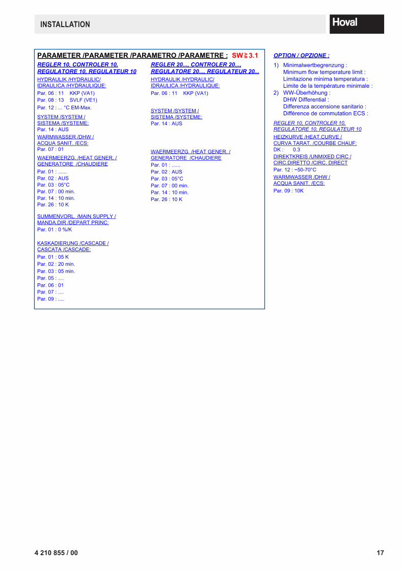
PARAMETER /PARAMETER /PARAMETRO /PARAMETRE :REGLER 10, CONTROLER 10, REGULATORE 10, REGULATEUR 10
REGLER 20..., CONTROLER 20..., REGULATORE 20..., REGULATEUR 20...
SYSTEM /SYSTEM /SISTEMA /SYSTEME:Par. 14 : AUS
SYSTEM /SYSTEM /SISTEMA /SYSTEME:Par. 14 : AUS
WARMWASSER /DHW /ACQUA SANIT. /ECS:Par. 07 : 01
Par. 08 : 13 SVLF (VE1)
HYDRAULIK /HYDRAULIC/IDRAULICA /HYDRAULIQUE:
HYDRAULIK /HYDRAULIC/IDRAULICA /HYDRAULIQUE:Par. 06 : 11 KKP (VA1)
WAERMEERZG. /HEAT GENER. /GENERATORE /CHAUDIERE Par. 01 : ......
Par. 14 : 10 min.
Par. 03 : 05°C
Par. 26 : 10 K
Par. 07 : 00 min.
WAERMEERZG. /HEAT GENER. /GENERATORE /CHAUDIERE Par. 01 : ......
Par. 14 : 10 min.
Par. 03 : 05°C
Par. 26 : 10 K
Par. 07 : 00 min.
KASKADIERUNG /CASCADE /CASCATA /CASCADE:Par. 01 : 05 K
Par. 03 : 05 min. Par. 02 : 20 min.
Par. 05 : ....Par. 06 : 01Par. 07 : ....Par. 09 : ....
Par. 06 : 11 KKP (VA1)
1) Minimalwertbegrenzung :Minimum flow temperature limit :Limitazione minima temperatura :Limite de la température minimale :
2) WW-Überhöhung :DHW Differential :Differenza accensione sanitario :Différence de commutation ECS :
REGLER 10, CONTROLER 10, REGULATORE 10, REGULATEUR 10HEIZKURVE /HEAT.CURVE /CURVA TARAT. /COURBE CHAUF:DK : 0.3DIREKTKREIS /UNMIXED CIRC / CIRC.DIRETTO /CIRC. DIRECTPar. 12 : ~50-70°CWARMWASSER /DHW /ACQUA SANIT. /ECS:Par. 09 : 10K
OPTION / OPZIONE :
SW 3.1=>
Par. 02 : AUSPar. 02 : AUS
SUMMENVORL. /MAIN SUPPLY /MANDA.DIR /DEPART PRINC:Par. 01 : 0 %/K
Par. 12 : ... °C EM-Max.
Version
Par. »Verbindungshinweise /Notice / Nota / Remarque:
.
Datei: KA090.vsd
Datum Name08.03.13Achtung ! Für die Installation muss das anlagenbezogene Schema verwendet werden!KA090.VSD
Attention! This is just a schematic. For installation please use the detail-plan!Attenzione! Per la messa in opera, utilizzare le schema dettagliato!Attention! Pour la réalisation pratique de l'installation, il faut utiliser le schéma détaillé!
.
+ Leg. LK010
7 / 7
PARAMETER /PARAMETER /PARAMETRO /PARAMETRE :REGLER 10, CONTROLER 10, REGULATORE 10, REGULATEUR 10
REGLER 20..., CONTROLER 20..., REGULATORE 20..., REGULATEUR 20...
SYSTEM /SYSTEM /SISTEMA /SYSTEME:Par. 14 : AUS
SYSTEM /SYSTEM /SISTEMA /SYSTEME:Par. 14 : AUS
WARMWASSER /DHW /ACQUA SANIT. /ECS:Par. 07 : 01
Par. 08 : 13 SVLF (VE1)
HYDRAULIK /HYDRAULIC/IDRAULICA /HYDRAULIQUE:
HYDRAULIK /HYDRAULIC/IDRAULICA /HYDRAULIQUE:Par. 06 : 11 KKP (VA1)
WAERMEERZG. /HEAT GENER. /GENERATORE /CHAUDIERE Par. 01 : ......
Par. 14 : 10 min.
Par. 03 : 05°C
Par. 26 : 10 K
Par. 07 : 00 min.
WAERMEERZG. /HEAT GENER. /GENERATORE /CHAUDIERE Par. 01 : ......
Par. 14 : 10 min.
Par. 03 : 05°C
Par. 26 : 10 K
Par. 07 : 00 min.
KASKADIERUNG /CASCADE /CASCATA /CASCADE:Par. 01 : 05 K
Par. 03 : 05 min. Par. 02 : 20 min.
Par. 05 : ....Par. 06 : 01Par. 07 : ....Par. 09 : ....
Par. 06 : 11 KKP (VA1)
1) Minimalwertbegrenzung :Minimum flow temperature limit :Limitazione minima temperatura :Limite de la température minimale :
2) WW-Überhöhung :DHW Differential :Differenza accensione sanitario :Différence de commutation ECS :
REGLER 10, CONTROLER 10, REGULATORE 10, REGULATEUR 10HEIZKURVE /HEAT.CURVE /CURVA TARAT. /COURBE CHAUF:DK : 0.3DIREKTKREIS /UNMIXED CIRC / CIRC.DIRETTO /CIRC. DIRECTPar. 12 : ~50-70°CWARMWASSER /DHW /ACQUA SANIT. /ECS:Par. 09 : 10K
OPTION / OPZIONE :
SW 3.1=>
Par. 02 : AUSPar. 02 : AUS
SUMMENVORL. /MAIN SUPPLY /MANDA.DIR /DEPART PRINC:Par. 01 : 0 %/K
Par. 12 : ... °C EM-Max.
18 4 210 855 / 00
InSTAllATIOn
LK01
0.vs
d10
.04.
12
Lege
nde_
DE
AFV
…An
lage
nvor
lauf
fühl
erAF
…Au
ssen
fühl
er
BUS-
T2B
…R
egel
gerä
te D
aten
bus
(Top
Tron
ic-T
)BU
S-O
T …
Wär
mee
rzeu
ger D
aten
bus
(Ope
nThe
rm)
B1 /
…
Vorla
ufte
mpe
ratu
rwäc
hter
(bei
Bed
arf)
*B2
…Ab
gast
empe
ratu
rbeg
renz
er
B5 …
Gef
ahre
nsch
alte
r Bre
nner
aus
, aus
serh
alb
Hei
zrau
m
(Brü
cke
entfe
rnen
), *)
wen
n Y6
Hau
ptga
sven
til
vorh
ande
n –
in S
erie
zu
Y6
ansc
hlie
ssen
B8 …
Was
sere
rwär
mer
–An
ford
erun
gB9
…Ab
gast
herm
osta
t für
Fes
tbre
nnst
offe
B11
…Ko
nden
sat -
Heb
esta
tion
B22
…U
msc
haltt
herm
osta
t Anf
ahre
ntla
stun
gB2
3 …
Fros
tsch
utz
-Tem
pera
turw
ächt
er
BZ (1
,2) …
Betri
ebss
tund
enzä
hler
(Stu
fe ,2
)
DK
P …
Pum
pen
für H
eizk
reis
ohn
e M
isch
er
E1/E
LH …
Elek
trohe
izei
nsat
z B
ival
ent
E1-W
W …
Elek
trohe
izei
nsat
z W
asse
rerw
ärm
er(T
empe
ratu
rrege
lung
ext
ern)
E2 …
Begl
eith
eizb
and
Kon
dens
was
sera
blau
fE3
…Ko
mpr
esso
rhei
zung
E4 …
Begl
eith
eizb
and
Vor
lauf
-Rüc
klau
f
EW/E
VU …
EW/E
VU S
perre
Wär
mep
umpe
E1-S
T …
Stro
man
schl
uss
Elek
trohe
izei
nsat
z
FA …
Feue
rung
saut
omat
FK …
Wic
klun
gssc
hutz
ext
ern
FKF
…Fe
stst
off -
Kess
elfü
hler
FM …
Mot
orsc
hutz
(bau
seits
, je
nach
Erfo
rder
nis
)FS
P …
Fest
stof
fpum
pe
CP
…C
onde
nser
pum
pe
F …
Strö
mun
gsw
ächt
er
HT
/ NT
…H
ocht
empe
ratu
r / N
iede
rtem
pera
tur
HD
/ N
D …
Hoc
h/N
iede
rdru
cksc
halte
rH
ST
…H
aupt
stro
man
schl
uss
A4P
,A7P
,A8P
..Zu
satz
plat
inen
IMP
…Im
puls
eing
ang
A-IM
P …
Impu
lsei
ngan
g St
rom
zähl
erF-
IMP
…Im
puls
eing
ang
Volu
men
sstro
mge
ber H
eizu
ngss
eite
YK1
,2,3
…S
tella
ntrie
b M
isch
er 1
,2,3
,...
YKR
1,2,
3 …
Ste
llant
rieb
Rüc
klau
fmis
cher
1,2
,3,..
.
YA
V …
Ste
llant
rieb
Anl
agen
vorla
ufm
isch
erY
Fc …
Ste
llant
rieb
Um
scha
ltung
Küh
lung
YK
K …
4-W
egev
entil
im K
älte
krei
s
Y6
…M
agne
tven
til (o
d. H
aupt
gasv
entil
)Y
6.1
…B
rand
schu
tz-/Ö
l-Mag
netv
entil
(1
Stra
ng Ö
lleitu
ng )
Y6.
2 …
Bra
ndsc
hutz
-/Öl-M
agne
tven
til
(2 S
trang
Ölle
itung
od.
Hau
ptga
sven
til )
Y3
…S
tella
ntrie
b U
msc
haltu
ng F
estb
renn
stof
f -/Ö
l-/G
as o
d.
Pel
lets
(Ein
drah
tste
ueru
ng )
Y7
…W
asse
rwei
che
od. S
tella
ntrie
b fü
r Was
sere
rwär
mun
g (E
indr
ahts
teue
rung
)Y
9 …
Ste
llant
rieb
Anf
ahre
ntla
stun
g (E
indr
ahts
teue
rung
)Y
10.1
,2,3
…A
bspe
rrorg
an o
d. -/
Zone
nven
til 1
,2,3
, ….
(Ein
drah
tste
ueru
ng)
KKP
1,2,
3 …
Kess
elkr
eisp
umpe
1,2
,3, .
..
MW
…W
ärm
eque
llenp
umpe
M1
…W
ärm
epum
penk
ompr
esso
rM
2 …
Wär
mep
umpe
nven
tilat
orM
5.1,
2,3
…Ke
ssel
krei
spum
pe 1
,2,3
, ...
M8
…Pu
fferla
depu
mpe
M20
…Zu
brin
gerp
umpe
Sch
wim
mba
d
MK
1,2,
3 …
Pum
pe M
isch
erkr
eis
1,2,
3, ..
.
P …
Dru
ckw
ächt
er
PP
…Pr
imär
pum
peP
LP …
Puffe
rlade
pum
pe
PF1
,2, …
Puffe
rfühl
er 1
,2,…
.
BP …
Puffe
rfühl
er
QF
…W
ärm
eque
llenf
ühle
rQ
1 …
Hau
ptsc
halte
r WP
RS
-T/R
FF-T
…R
aum
stat
ion
/ Fer
nbed
ienu
ng (f
alls
meh
rere
Ger
äte
para
llel a
nsch
liess
en )
SH
…H
aupt
scha
lter m
it m
in. 3
mm
Kon
takt
abst
and,
au
sser
halb
Hei
zrau
m
SF
…W
asse
rerw
ärm
erfü
hler
SB-
R1(
3)K
…Sy
stem
baus
tein
(Rel
ais)
SB-
STW
…R
elai
sbau
satz
Strö
mun
gsw
ächt
erS
B-G
WP
…Sy
stem
baus
tein
Gru
ndw
asse
rpum
pe
SLP
…W
asse
rerw
ärm
erla
depu
mpe
SLV
…W
asse
rwei
che
Sol
arkr
eis
(Ein
drah
tges
teue
rt )
SLV
F …
Sola
rfühl
er (W
asse
rerw
ärm
er -/
Puf
fers
peic
her)
SO
P1,
2,...
Sol
arkr
eisp
umpe
1,2
,….
STW
...
Strö
mun
gsw
ächt
er
BW …
Was
sere
rwär
mer
fühl
er
SVL
F ...
Sum
men
vorla
uffü
hler
SST
...
Ste
uers
trom
ansc
hlus
s
S1,
2,3
...D
iffer
enzs
teue
rung
sfüh
ler 1
,2,3
,...
S8
...E
xter
ner S
chal
ter:
Fest
stof
f/Aut
o, S
olar
/Aut
o, E
in/A
us
KVL
F …
Sola
rfühl
er (K
olle
ktor
–PT
1000
)K
SPF
…So
larfü
hler
(Was
sere
rwär
mer
-/P
uffe
rspe
iche
r)
KR
LF …
Sola
rfühl
er (R
ückl
auf)
KF
…Ke
ssel
fühl
er
RLF
1,2,
…R
ückl
auffü
hler
1,2
, ...
BRU
…R
ückl
auffü
hler
VF1
,2,3
...
Vor
lauf
fühl
er 1
,2,3
, ...
VE1
,2,3
...
Var
iabl
er E
inga
ng 1
,2,3
, ...
VA1
,2,3
...
Var
iabl
er A
usga
ng 1
,2,3
, ...
WF1
,2,3
...
Wär
mee
rzeu
gerfü
hler
1,2
,3, .
..
ZUP
1,2,
3, …
Zubr
inge
rpum
pe 1
,2,3
, …
GW
F ...
Gru
ndw
asse
rfühl
erG
WP
...G
rund
was
serp
umpe
CV
F1,2
…C
onde
nser
vorla
uffü
hler
1,2
, ...
RLP
1,2,
3 …
Bypa
sspu
mpe
Rüc
klau
fhoc
hhal
tung
1,2
,3, …
.
M10
.1,2
,3 …
Bypa
sspu
mpe
Rüc
klau
fhoc
hhal
tung
1,2
,3, …
.M
16 …
Pum
pe fü
r Abg
asw
ärm
etau
sche
r
B4 …
Türk
onta
ktsc
halte
r Fes
tsto
ffkes
sel (
bei B
ival
enta
nlag
eje
nac
h Lä
nder
vors
chrif
t wen
n 1
Kam
in)
B7 …
Was
serm
ange
lsic
heru
ng
B10
…M
inim
alth
erm
osta
t im
Fes
tbre
nnst
offk
esse
l
B14
…M
axim
alth
erm
osta
tB1
5 …
Ther
mos
tat R
ückl
aufh
ochh
altu
ng
AUE
…Au
tom
atis
che
Um
scha
ltein
heit
(Vor
rats
raum
)sse
nfüh
ler
AUE-
S …
Ends
chal
ter A
utom
atis
che
Um
scha
ltein
heit
(Vor
rats
raum
)
AST-
V …
Aust
ragu
ng V
orra
tsra
um (S
chne
cke)
AST-
SV
…Au
stra
gung
Vor
rats
raum
(Sau
ger)
AGF
…Ab
gasf
ühle
r
M9
…La
depu
mpe
Spe
iche
r 1 z
u Sp
eich
er 2
BUS-
RS
485
…W
ärm
eerz
euge
r Dat
enbu
s
STB
...
Sic
herh
eits
tem
pera
turb
egre
nzer
KTR
…Ke
ssel
tem
pera
turre
gler
BA …
Auss
enfü
hler
TKS
-V ..
.Tü
rkon
takt
scha
lter V
orra
tsra
um
SB-
GE
…Sy
stem
baus
tein
Geh
äuse
YFW
…V
olum
enst
rom
regl
er
SM
…S
törm
eldu
ng
ZKP
…W
arm
was
serz
irkul
atio
nspu
mpe
SSP
...
Sch
icht
spei
cher
pum
pe
SLF
…Sp
eich
erla
defü
hler
BFSV
…La
gerr
aum
Fül
lsta
ndsc
halte
r
+ Be
i Fus
sbod
enhe
izun
g is
t ein
Vor
lauf
tem
pera
turw
ächt
er
einz
ubau
en.
+ Sä
cke
zur V
erhi
nder
ung
von
Einr
ohrs
chw
erkr
aft-z
irkul
atio
nen
einb
auen
!
+ A
bspe
rrorg
ane
zu d
en S
iche
rhei
tsei
nric
htun
gen,
(D
ruck
ausd
ehnu
ngsg
efäs
s, S
iche
rhei
tsve
ntil,
usw
. ...)
sin
d ge
gen
unbe
absi
chtig
es s
chlie
ßen
zu s
iche
rn !
+ Be
im H
ydra
ulik
-/Ele
ktro
sche
ma
hand
elt e
s si
ch u
m P
rinzi
psch
ema
das
nich
t alle
Ang
aben
für d
ie In
stal
latio
n be
inha
lten.
Inst
alla
tion
nur
durc
h ko
nzes
sion
ierte
n Fa
chm
ann
nach
den
örtl
iche
n G
egeb
enhe
iten,
Dim
ensi
onie
rung
en, u
nd V
orsc
hrift
en .
Wic
htig
e H
inw
eise
:
Klem
men
= S
ie fü
hren
Kle
insp
annu
ng u
nd d
ürfe
n ni
cht a
n da
s N
etz
ange
schl
osse
n w
erde
n. D
iese
Lei
tung
en s
ind
in
eine
m s
epar
aten
Kab
el z
u ve
rlege
n. A
CH
TUN
G! B
ei B
us-L
eitu
ngen
si
nd d
ie V
erdr
ahtu
ngsr
icht
linie
n zu
bea
chte
n !
RA
S ...
Unt
erdr
ucks
chal
ter R
aum
aust
ragu
ngst
urbi
ne
ASS
…As
ches
chie
ber
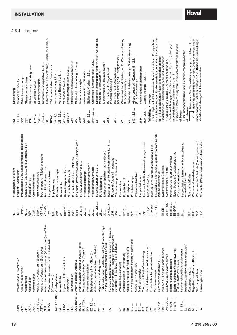
4.6.4 Legend

194 210 855 / 00
confirmation
The user (owner) of the system herewith confi rms that• he has received adequate instruction in the operating and maintenance of the installation,• received and taken note of the operating and maintenance instructions and, where applicable other documents con-
cerning the heat generator and any further components.• and is consequently suffi ciently familiar with the installation.
Installation address: Type:
Serial number:
Year of manufacture:
Place, Date:
System installer: System user:
cOPy FOr PlAnT USEr
cOPy OF SySTEm InSTAllEr