Embed Size (px)
Citation preview

.. i RECEIVED BY DTIE SEP 2 5 1969.
IAEA-SM-125/62
ARH-SA-39APPROV
ED FOR
vkh(ef/F i f SEP 16 19694. 1- colt 1 61 PUBLICATION
p''r .ACle w F'F-.6 9 100%-1
THE CONZINUD.US_INCI.NERA-TIDN-OXPLUTONIUM-BEARING SCRAP
Lee M.· Knight s
Manager, Plutonium Process Engineering SectionOperations Support Engineering Department
ATLANTIC RICHFIELD HANFORD COMPANY
Richland, Washington, U.S.A.
September 15, 1969
LEGAL NOTICEThla report was prepared aa an account of Government aponsored work. Neither the UnitedState 0, no r the Commia 8 ton, nor any person acting on behalf of the Com mi ia i on:
A. Make, any warranty or representation. expressed or Implied. with respect to the accu-
my. completeness, or useful ma of the informotion contained in this report, or that the useof any informatlon, apparatus, method. or process dtrcl...d in this report may not infringeprlvately owned rights; or
B. Assumes any ilabililes with reapect to the use of, or for damages resulting from theuse of any intormauon, apparatus, method. or process disclosed In Lhts report.
Ae used in the above, "Per son acting on behalf of the Comintiaton" includes any em-ployee or contractor of the Commtialon, or employee of such contractor, to the extent thatauch employee or contractor of the Commisa on, or employee of such contractor pre res,B.eminates, or provide. acces... any informallon F...ant to his employment or contractwith the Commission, or his employment with such contractor.
'2940
CSTROUrION Q) 06 'S ODCUMEI)11 ,15 .UNUMI re,
L

DISCLAIMER
This report was prepared as an account of work sponsored by anagency of the United States Government. Neither the United StatesGovernment nor any agency Thereof, nor any of their employees,makes any warranty, express or implied, or assumes any legalliability or responsibility for the accuracy, completeness, orusefulness of any information, apparatus, product, or processdisclosed, or represents that its use would not infringe privatelyowned rights. Reference herein to any specific commercial product,process, or service by trade name, trademark, manufacturer, orotherwise does not necessarily constitute or imply its endorsement,recommendation, or favoring by the United States Government or anyagency thereof. The views and opinions of authors expressed hereindo not necessarily state or reflect those of the United StatesGovernment or any agency thereof.

DISCLAIMER
Portions of this document may be illegible inelectronic image products. Images are producedfrom the best available original document.

ARH-SA-39
FAASTER
THE CONTINUOUS INCINERATION OF PLUTONIUM-BEARING SCRAP
Lee M. Knights
Atlantic Richfield Hanford CompanyRichland,·Washingtori, U.S.A.
INTRODUCTION
The Atlantic Richfield Hanford 'Company at Richland, Washington, hasa contract to. operate the chemical processing facilities for the Atomic
Energy Commission. Irradiated fuels and target materials are dissolvedand elements Of interest are separated and purified by the Purex process.Much of the plutonium nitrate solution produced is processed further tooxides or metal. Plutonium-bearing scrap, much of which is bulky andincinerable, is a normal by-product of the processing, and the quanti-ties of plutonium are often economically attractive to recover. AContaminated Waste Recovery Facility, which included both incinerationand leaehing equipment, was built in 1961 to recover plutonium fromthese sclap materials. During eight years of operation, a considerableamount of practical experience has been gained and used to improve theperforniance of the unit..
DESCRIPTION OF PROCESS
The incinerator was designed for continuous operation, with
emphasis on (a) reduting· the size of· the unit to glove box proportions,(b) minimizing the problems of contamination control while charging.feed, and. (c) using geometric limitations wherever possible to assurecriticality prevention.
-1-

...
..
ARH-SA-39
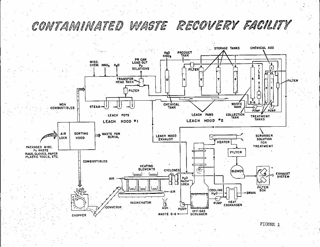
A flow diagram of the process is shown in the first slide. Waste-filled cartons are introduced through an airlock into a sorting hood.
Sorting is manual. Leachables are fed to a leach hood. Some waste,tools, sharp objects, etc., are discarded after the absence of econom-ically recoverable plutonium has been confirmed by gamma or neutron counting. Smooth metal objects, for instance, may be wiped with ragsand discarded. The rags are then incinerated.
Most all of the plastic and rubber materials, including gloves,·are treated as noncombustibles because of the large amount of sootformed in burning and because of the corrosi6n resulting from chloriderelease. The noncombustibles are leached in nitric·acid in trays orin steam-heated pots. The leached scrap is discarded after evaluationof plutonium content.
Combustibles are shredded in the chopper and conveyed on a belt tothe incinerator, where a second belt carries them through the primary
combustion chambers. The off-gas passes through a secondary combustionchamber and then through two cyclone separators in series. Ash fromthe cyclones and combustion chamber is collected in small iron cans andtransferred to dissolution and reprocessing facilities elsewhere. Theoff-gas is treated by scrubbing with a counter-current spray of sodiumhydroxide to neutralize acidic gases. Small amounts of urea are usedto neutralize hypochlorite, which is generated when burning someplastics. Cooling is effected in the scrubber by circulating thesodium hydroxide through water-cooled heat exchangers. When thescrubber solution is spent, the plutonium content associated with thefine solids in it approximate 0.05 to 0.1 gram per liter. Provisionswere made for filtration of· the plutonium-bearing fines in the leachhood.
The cooled off-gas from the scrubber is heated above its dew pointby an electric· heater to prevent. condensation of moisture on the high-efficiency filters. The blower, pulling a slight vacuum on the entire
system, discharges to the main building stack via two more high-
. efficiency filters it series.
DESCRIPTION OF EQUIPMENT AND CONTROLS
A :cutaway of the Contaminated Waste Recovery Facility in the nextslide shows the principal features of the incinerator, the leach hoods,and the off-gas system. The chopper is a rotating drum ·with blades set
in the. periphery, parallel·to the axis. The chopper has given excel-lent service on rags, papers, plastic, wood, .and asbestos filter elements.
-2-

ARH-SA-39
The feed conveyer is a conventional cleated rubber conveyer belt
with a variable speed drive. The furnace belt, which is also equippedwith a variable speed drive, is woven of Nichrome-V wire, an 80 percentnickel - 20 percent chromium alloy.
The furnace is three meters long and is fabricated of Incalloy 800
(32 percent nickel, 20.5 percent chromium, ·and 46 percent iron alloy)and 321 stainless steel (a steel of 17 - 19 percent chromium and 8 - 11percent nickel). The lower horizontal member is a semicylinder 20.3centimeters in diameter, with a flat bottom which serves as a floor forthe.furnace belt. This is the primary combustion chamber. Above this,four flue risers connect with the upper (or secondary) 12.7 centimeterdiameter combustion chamber. The furnace is shielded by 45 centimetersof firebrick insulation and the Whole unit contained in a stainlesssteel gloved box.
The ·incinerator target temperature of 700 - 8000 C is controlledprimarily by the voltage applied to three 32 kw resistance heatingelements. Feed rates and the incinerator belt speed also have an effecton temperature control. Residence time in the combustion chamberaverages eight minutes. Air flow to the primary and secondary com-bustion chambars, indicated by rotameters, is approximately 0.2 cubic
meter/minute.
The incinerator off-gas discharges through a combustible gas
analyzer set to alarm at one percent combustihles in the off-gas.There has been no confirmed alarm from this analyzer. The gas.thendischarges through two cyclone .separators in series. A small adjoiningroom houses the off-gas scrubber, which is 0.35 meter inside diameterby 2.7 meters high, set on a 0.75 meter diameter by 0.70 meter highpump tank. The scrubber contains a quench ·spray section, two impinge--ment baffles, and a high velocity baffle plate stage. The originalmoisture de-entrainer (vane type) has been replaced with a tetra-
fluoroethylene mesh de-entrainer. Construction is 316 stainless steelthroughout (10 - 14 percent nickel, 16 - 18 percent chromium, 1.75 -2.5 percent molybdenum.steel). Two heat exchangers cool the circulating
sodium hydroxide solution.. Rated efficiency of the scrubber system is. -greater than 90 percent for all particles larger than 0.3 micron indiameter.
Air flow to the scrubber includes both the incinerator off-gas andthe leach hood exhaust. It is regulated for proper scrubbing action bya butterfly valve in the leach hood exhaust line. Rotameters indicate.
-3 -
ARH-SA-39
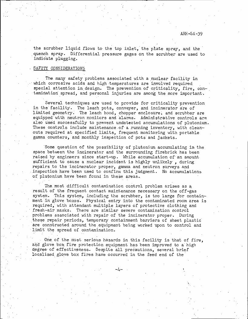
the scrubber liquid flows to· the top . inlet, the plate spray, and thequench spray. Differential pressure gages on the scrubber are used toindidate plugging.
. SAFETY CONSIDERATIONS
The. many safety problems associated with ·a nuclear facility inwhich corrosive acids and high·temperatures are involved requiredspecial attention in design. The prevention of criticality, fire, con-tamination spread, and personal inj uries are among the more important·.
Several techniques ·are used to provide for criticality preventionin the facility. The leach pots, conveyer, and incinerator dre oflimited geometry. The leach hood, chopper enclosure, and scrubber areequipped with neutron monitors and alarms. Administrative controls arealso used successfully to prevent undetected accumulations of plutonium.The se controls include maintenance. of· a .running inventory, with clean-outs required at specified limits, frequent monitoring with portablegamma counters, and monthly inspection of pots and jackets.
Some question of the possibility of plutonium accumulating in thespace between the incinerator and the surrounding firebrick has beenraised by. engineers since start-up. While accumulation of an amouhtsufficient to cause a nuclear incident·is highly unlikely , duringrepairs to the incinerator proper, gamma and neutron surveys and.inspection have been used to confirm this judgment. No accumulatiohsof plutonium have been found in thehe areas.
The.most difficult contamination control problem arises as a
result of the frequent contact maintenance necessary on the off-gassystem. This system, including the scrubber, is too large for contain-ment .in glove boxes. Physical entry into the contaminated room area isrequired, with attendant multiple layers of protective clothing andfresh-air masks. There are similar severe contamination controlproblems associated with repair of the incinerator proper. Duringthese repair periods, temporary containment barriers of sheet plastic
are·constructed around the equipment being worked upon to control andlimit the spread of contamination.
One of the· most serious hazards in this facility is that of fire,and glove box fire ·protection equipment has been improved to a highdegree· of effectiveness. Despite all precautions, several brieflocalized glove box fires have occurred in the feed end of the

ARH-SA-39
incinerator and the chopper effluent hopper. These fires were causedby flashback from the incinerator. A wire screen placed in the feed
end of the incinerator has been very·effective in preventing flashback.Also, nitrogen is added at .the primary combustion chamber inlet to helpprevent flame blow-back.
The chopper enclosure is protected with heat sensing elementswhich activate an alarm when heated to 88' C. At the same time, alimited (by criticality prevention considerations) supply of water isapplied automatically in the enclosure through four spray nozzles. Thesystem may also be operated manually. All glove boxes are fitted withattachments to allow introduction of carbon dioxide or dry chemical(sodium carbonate) from external portable extinguishers. Glove portsnear the incinerator are protected with heat shields at all times it is
in operation.
The entire building.is provided with fire detectors which activatealarms in appropriate lacations, including the area's central fire
department. In addition, there is an automatic COR extingui shmentsystem of the total flooding type which protects the storage roomhousing boxes of scrap awaiting processing.
Protection for the operator's hands·was provided by equipping thechopper with two "start" buttons widely spaced .on the exterior of theglove box. These must be ptessed simultaneously to start the chopper.Thus,·the operator must remove both hands from the vicinity of the
chopper before he can start it.
MAINTENANCE
The more serious maintenance problems have included furnace
failures, inadequate temperature control, accumulation of solids in theoff-gas. system, and short furnace belt life. In 1963, the originalcombustion chamber failed and was replaced.
The original incinerator was a one-piece unit welded from sections
of cast high temperature, high nickel alloy steel. This incineratorwas removed when massive fractures of the chamber occurred after oneyear of operation due to the effects of thermal expansion and con-traction. After 22 more months, failure occurred a second time,prompting complete redesign of the combustion chamber to eliminatedifferential thermal expansion stresses between its various members.This is shown in the next slide. The redesign eliminated the all-welded construction, and in its place, ball .and ·socket and slip joints
-5-
,

ARH-SA-39
were installed at the top and bottom of each of the .flue tube risers.This unit performed for only nine months when stress corrosion crackingoccurred. The furnace was constructed of Incalloy 800, both wroughtand cast.
Investigation revealed that the cause of failure was high temper-ature and temperature cycling outside the 700 - 800'·C range as aresult of excessive feed rates. Further, in a portion of the combus-tion chambers, a rotationally cast Incalloy 800 ·material was used ·whichhad extremely large grain structure. These sections were replaced withwrought 321 stainless steel. In addition, temperature sensors weremoved from the exterior wall of the incinerator and placed directly inthe off-gas. This provided improved control because of its fasterresponse. This incinerator has been running for two years withoutfailure, with down time necessitated only by problems with the off-gastreatment equipment.
Stretching of the wire mesh furnace belt is a recurring problem,but has been reduced by selection of improved alloys. Addition of apositive belt drive was also helpful, and this was achieved by addingspots of weld metal on the drive drum. More careful attention duringsorting, to keep tramp metal out of the choppers and belts, has beenhelpful. Belts · currently in use cost about $500 and are giving up to 'six months of service before replacement is necessary. Changing of theincinerator belts is accomplished by spot welding a new belt to the oldbelt and pil]_ling the new belt into position as the old belt is z'emoved.
A continuing problem has been the lack of good air flow controlthrough the incinerator. There is no direct control here, since totalair input varies as the leach hood exhaust is varied, and this greatlyaffects the.collection efficiency of the cyclones.
De-entrainer pads were added to the scrubber to reduce·liquidentrainment to the filters. With a constant sodium hydroxide spray,these must be replaced every three to four weeks. Plugging occurs intwo weeks if the spray is not applied continuously.
Cleaning the flue risers in the incinerator without dismantlingthe whole system was accomplished with ingenuity. A .spade-shapedpiece of .carbon steel, knopm as a "knocker head" in the boiler industry,was. threaded on a short· flexible ·shaft. Entering from the end of thetop combustion chamber, a. curved piece of pipe around the shaft guidedthe spade into the vertical flues. Sections of rod are added to the
-6-
L-

ARH -S A -39
shaft to extend the spade to the furthest flues. Rotation of the spadeis provided with a.variable speed reversible motor and the flue iseffectively freed of soot.
PERFORMANCE
Accurate assessment of the plutonium input is difficult because ofthe heterogeneous nature of the scrap. It is estimated that about98 percent. of the plutonium entering the facility·is recovered in theash and leach solutions. Unrecoverable plutonium is routed to under-grouhd storage. Only trace plutonium is found on the filters down-stream of the scrubber through which air is exhausted to the .stack.For the material .actually incinerated, there ·is a. volume reduction of98 percent.
Leaching of the incinerator ash product in a mixture of boiling9 - 10 molar nitric acid and 0.5 - 0.7 molar hydrofluoric acid hasproved to be a fairly effective means of plutonium recovery. Thefilterability of the leached ash presents operating problems, as theresidues are fine and have a pronounced tendency to blind filters.Filterability has not been consistently improved by use of varioustypes of deflocculating agents or filter precoats. Recent experimentalwork indicates that poor filtration of ash leach solutions is caused inmajor part by incomplete combustion. When reburned for an additional20 minutes,.the ash loses about 25 - 30 percent of its weight, The ashfrom this re-ignition leaches more completely and is· much more easilyfiltered.
Performance of the cyclone separators is variable and stronglydependent upon off-gas flow rates. Normally, it has been estimatedthat they.remove about 98 percent of the solids in the off-gas.
Occasiohally their efficiency is almost negligible. Particle size dataon these solids are not available.
Throughput rates are quite dependent on manpower availabilitybecause of the many hand operations in sorting, leaching, and belt-feeding. Full capacity operation requires a crew of four to five menper.eight-hour shift, In this time, three 0.13 cubic meter boxes canbe sorted and processed. Presently, the incineration and leaching ofscrap is current with generation rates and excess capacity exists.It.was estimated that economic payout of the facility was achievedduring its first year of operation..
-7- ',
ARH-SA-39
On the basis of experience to date,. there are two· recommendationsto be made in the design of a new facility. First, there should beimproved access to the system for clean-out of the flues and combustionchambers. Second, more positive controls on air input to the incin-erator are required to provide better control of off-gas handling andto provide uniformly high cyclone efficiency. Better air controls,
coupled with increased residence time in the incinerator, would providemore complete combustion and, in turn, would enhance subsequentdissolution of the ash.
Taking into account the rugged nature of the process and the
equipment requirements, it has been concluded that the large-scaleincinerator and leaching facility described has contributed materiallyto the recovery of plutonium-bearing scrap in the Atlantic RichfieldHanford Company at Richland, Washington.
-8-
IAEA-SM-125/62
ARH-SA-39
.
ILLUSTRATIONS ATTACHED
FIGURE 1: CONTAMINATED WASTE RECOVERY FACILITY(Process Flow Diagram)
FIGURE 2: CONTAMINATED WASTE RECOVERY FACILIlY(Cutaway)
FIGURE 3: INCINERATOR FOR PLUTONIUM RECOVERY
CONTAMINATED WASTE RECOVERY FACILITY
... STORAGE TANKS CHEMICAL ADD
H£O PRODUCTHNOS TANK
PR CAN r | A IMISC. LOAD OUT
1./1 \1 lE 'iCHEM. H.,3 ·,« P. 1 f-Er-3-/ t '-1111 SOLUTIONSFILTER UJ
TRANSFER to O 0« 7 6 5 R ...
HEAD TANK *FILTERt
910*FILTER I T -, / '3,0-
77 ..f -- , /1 I 1,7 ¢ ,NON-W -t'.1 -1 CHEMICAL WASTE 11
1 iii-COMBUSTIBLES STEAM T NK TANK /rl---·FJ V \ Pii,Ap V PUMPLEACH POTS LEACH PANS COLLECTION
' TANK TREATMENT
LEACH HOOD #l LEACH HOOD "2 TANKS-
\A# AIR SORTING TIA WASTE FOR
/ »'" Y LOCK HOOD BURIAL LEACH HOOD SCRUBBEREXHAUST 15> SOLUTION
r t HEATER h FORPACKAGED MISC. TREATMENTPu WASTE '
RAGS,GLOVES, PAPER FILTERPLASTIC TOOLS, ETC.
COMBUSTIBLESHEATING
ELEMENTS BLOWE4 fS--4 EXHAUSTCYCLONES - 5
1.....1 lillI. 1 445B9/M"'
I /1,
AIR I
1
al i HEO (-3 SYSTEM>-E g NaOH-1 . U -.- Jwww FILTERL.11 U UREA /1
-»,1 j 1-r» -te-AIR . . COHO2L0' f--. DRAIN
BOX
.f« INCINERATOR N rL Y.1=\ -r f PUMP HEAT
4 )1 -// U 1 66&4..Rd EXCHANGER/ ,/ CONVEYOR ASH PUMPI
.:»r:.=bl'..'.41 6 1 OFF-GAS
CHOPPER C WASTE D-6- SCRUBBER
FIGURE 1

THE CONTINUOUS INCINERATION OF PLUTONIUM-BEARING SCRAP
(ARH-SA-39)
'
Lee M. Knights
FIGURE 1
CONTAMINATED WASTE RECOVERY FACILITY
(Flowsheet)

CONTANI NATED WASTE RECOVERY FACILITY
COOLING WATERLEACH HOOD 2
LEACH HOOD EXHAUSTFILTER BOX I
LEACH HOOD I
X ,1 1':, \ - ----I Ll--- HEATERAIRLOCK
./
.r 191-««-v--71»' 8 -+ -
\\ ..\..: :'.-:i'..-'.,
«=11.-11111 n 0 r ,=...pr FILIER
11-/--,Sti 1 I.il tli U»f . -.' " '1 <1
'Ul S.Il,
1 HEAT EXCHANGER...I
lins- Ty.1 /..1 *1.- 91»" 0. : ' -C. .
X '1.-»1 = 1 .: oo,0 --1.1 SCRUBBER\ 1,..#\ - 4
-/ #1Z-7 BLOWER
51 41}113'·,1 29 N ir: .t k:-1
/3-> 111 s. f S oo.' 041
... 3
/ \ 0 J l< It 4...1 - »/ ASH CANNING HOOD
/ " »5, C r. ...3 /71# S.....,
: \1
Z . 'Crtists Warr,Mth *2PANEL
, e .COMBUSTION CHAMBER
SORTING HOOD INCINERATOR
CHOPPER
FEED CONVEYOR
FIGURE 2 ,

*
.
THE CONTINUOUS INCINERATION OF PLUTONIUM-BEARING SCRAP
(ARH-SA-39)
Lee M. Knights
FIGURE 2
CONTAMINATED WASTE RECOVERY FACILITY
(Cutaway)
*
*.
4,

80'9&04719 93 etru W rWinktO W \te
LOOSE FILL INSULATION HEATING ELEMENTS (TYP)ROLLER
REFRACTOR SUPPORT (TYP)SUPPORTS UPPER BALL JOINT (TYP)
.....--- . S»--· 4 ,-- · SPRING SUPPORTS1 ---41<-----.... ...........'...1.2-rt=-M -"."-- - -9.
SECONDARY COMBUSTION 00440 r .5--9 -U- -, ·„9 4(--- ---'...1 -»,- 1 -" - 7 .. ' a / j -......1'n-*-CHAMBER- -= -'--It*"...«- p#-9.7' 3/-'1 , ' - *104'%
EXPANSION
JOINTS
6 '1 1 -7,-4, 1, ..1 1» '4.2 11 - ikI«':d '»« !,<\ ' . --,-='' i ..4- '".... t.,1,/ -4,« -1 ..1>s, , r -Lt·Pi£ (9* -To OFF-GAS SCRUBBER
CYCLONE INSULATION
i ...1" .\It tl - 4 -73 W'_._.-Zimx=-CYCLONE ASH SEPARATORSFEED CONVEYOR -4 I 'L O ' -
FROM HOPPER
6 ./.. -4-t Ye 1--/lr .C'g I: .- 1 --- : 0 -..
)./.. ..i.*t 9,/6·- - CAN
4 n --: f L... .· .. ---..4.- ''t»'39
LOWER BALL JOINT (TYP)IA'&:-,5479- . -0*.t if»KI.'\REFRACTORY W '19 -© 9
PRIMARY COMBUSTION CHAMBER
1 4143 t,»444 - #P"
-ASH
BLOWER <«I,--» \ '' // WOVEN WIRE CONVEYOR BELT
FILTER «»« XSLIP JOINT (TYP)
\FLUE TUBE (TYP)_ HOPPER
ANCHOR
ROTAMETER (TYP) 1 \ASH CANNING GLOVE BOX
FIGURE 3

I ,
.
.
THE CONTINUOUS INCINERATION OF PLUTONIUM-BEARING SCRAP
R
(ARH-SA-39).t
Lee M. Knights"
/ I
.
FIGURE 3
INCINERATOR FOR PLUTONIUM RECOVERY .
4
*.
*
' #