Embed Size (px)
Citation preview
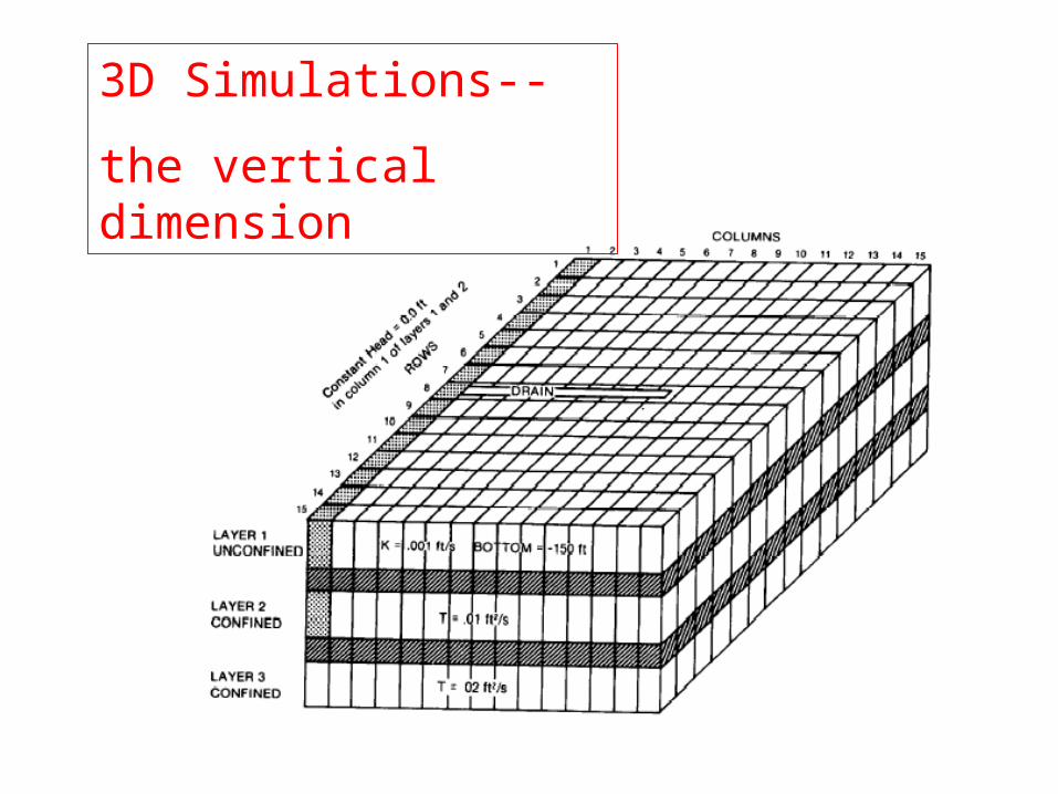
3D Simulations--
the vertical dimension
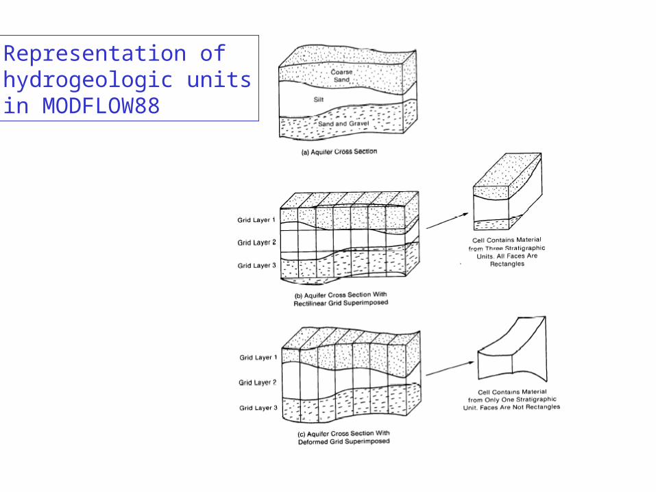
Representation ofhydrogeologic unitsin MODFLOW88
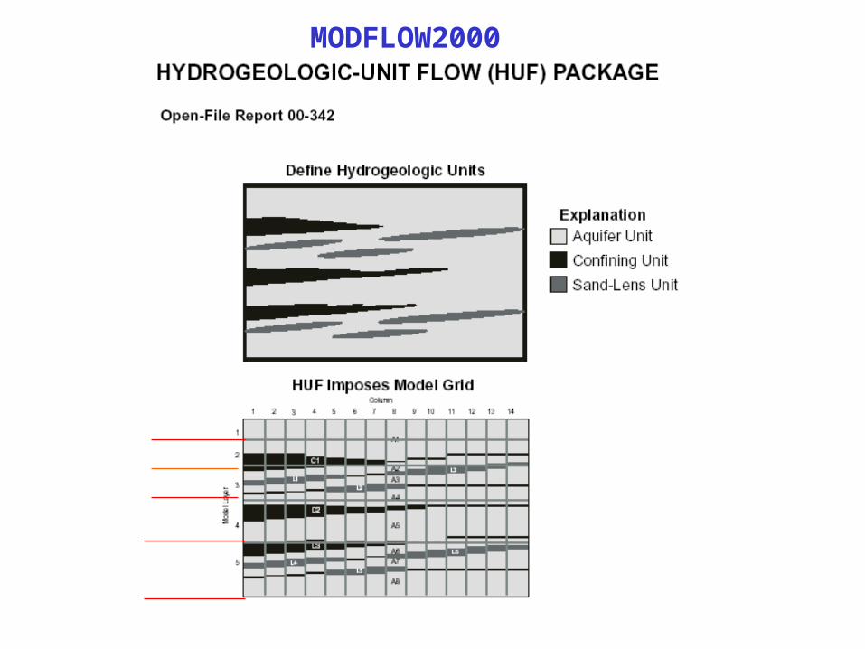
MODFLOW2000
In MODFLOW, vertical flow between layersIs governed by vertical conductance.
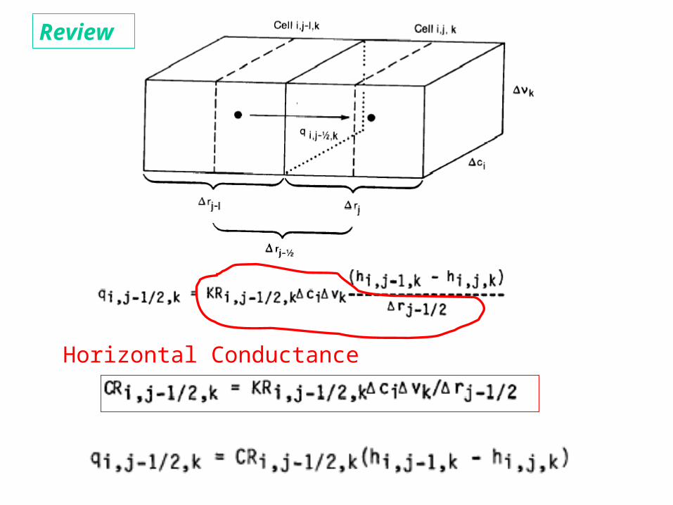
Horizontal Conductance
Review
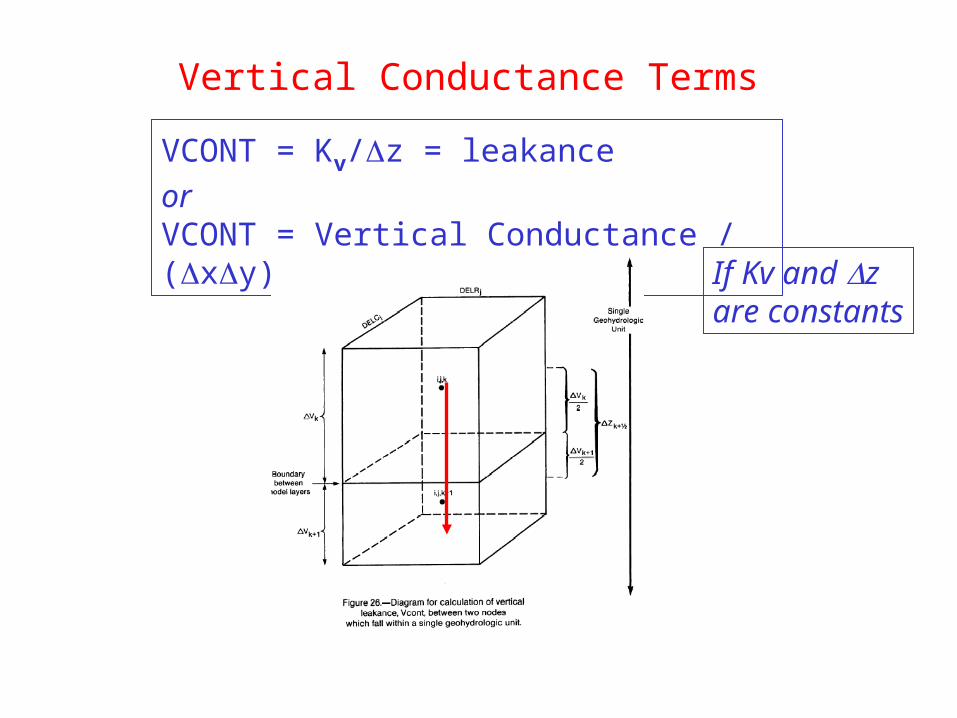
Vertical Conductance Terms
VCONT = Kv/z = leakance
or VCONT = Vertical Conductance / (xy) If Kv and z
are constants
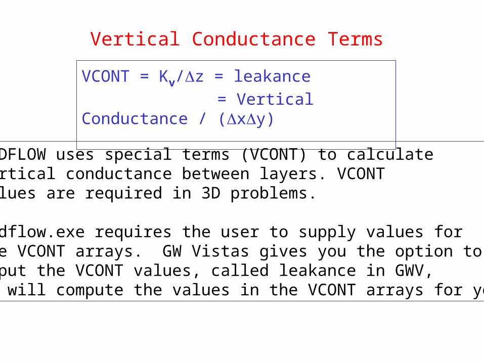
Vertical Conductance Terms
VCONT = Kv/z = leakance
= Vertical Conductance / (xy)
MODFLOW uses special terms (VCONT) to calculatevertical conductance between layers. VCONTvalues are required in 3D problems.
Modflow.exe requires the user to supply values forthe VCONT arrays. GW Vistas gives you the option toinput the VCONT values, called leakance in GWV,or will compute the values in the VCONT arrays for you.
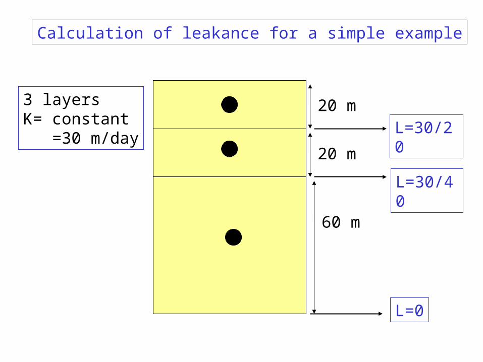
3 layersK= constant =30 m/day
20 m
60 m
20 m
L=30/20
L=0
L=30/40
Calculation of leakance for a simple example
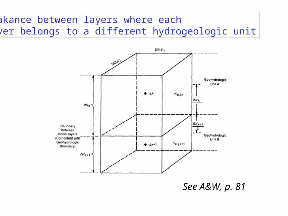
Leakance between layers where eachLayer belongs to a different hydrogeologic unit
See A&W, p. 81
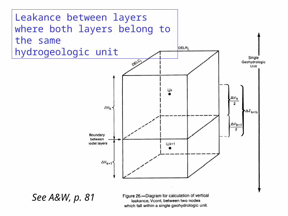
Leakance between layers where both layers belong to the samehydrogeologic unit
See A&W, p. 81
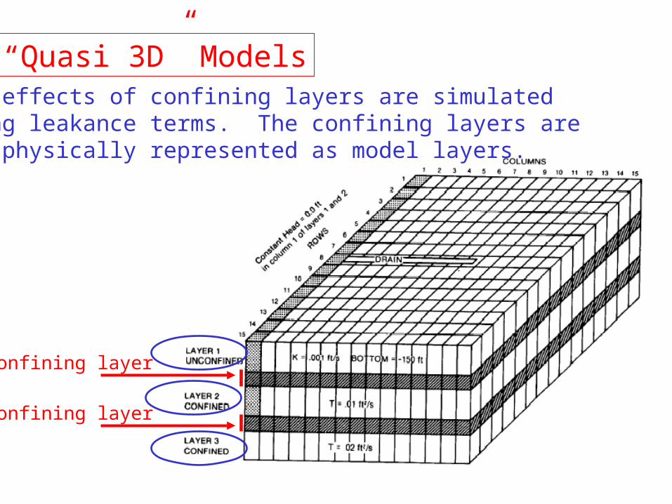
“Quasi 3D” ModelsThe effects of confining layers are simulatedusing leakance terms. The confining layers arenot physically represented as model layers.
Confining layer
Confining layer
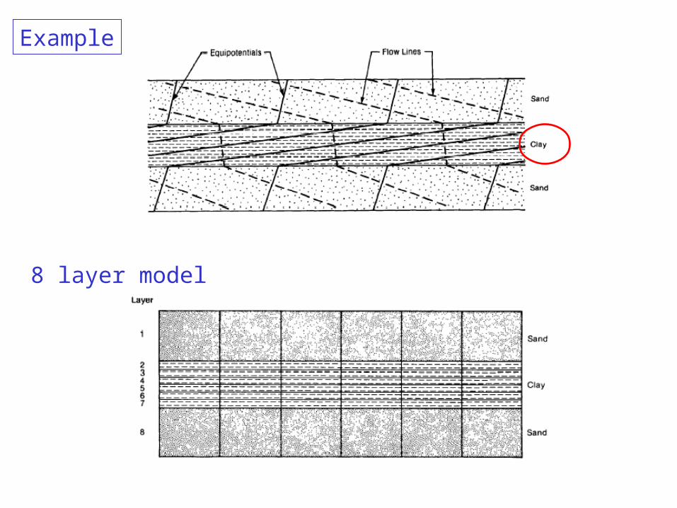
8 layer model
Example
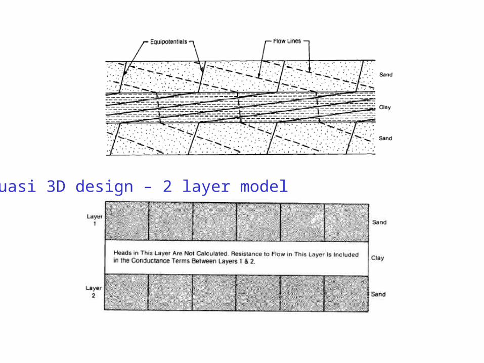
Quasi 3D design – 2 layer model
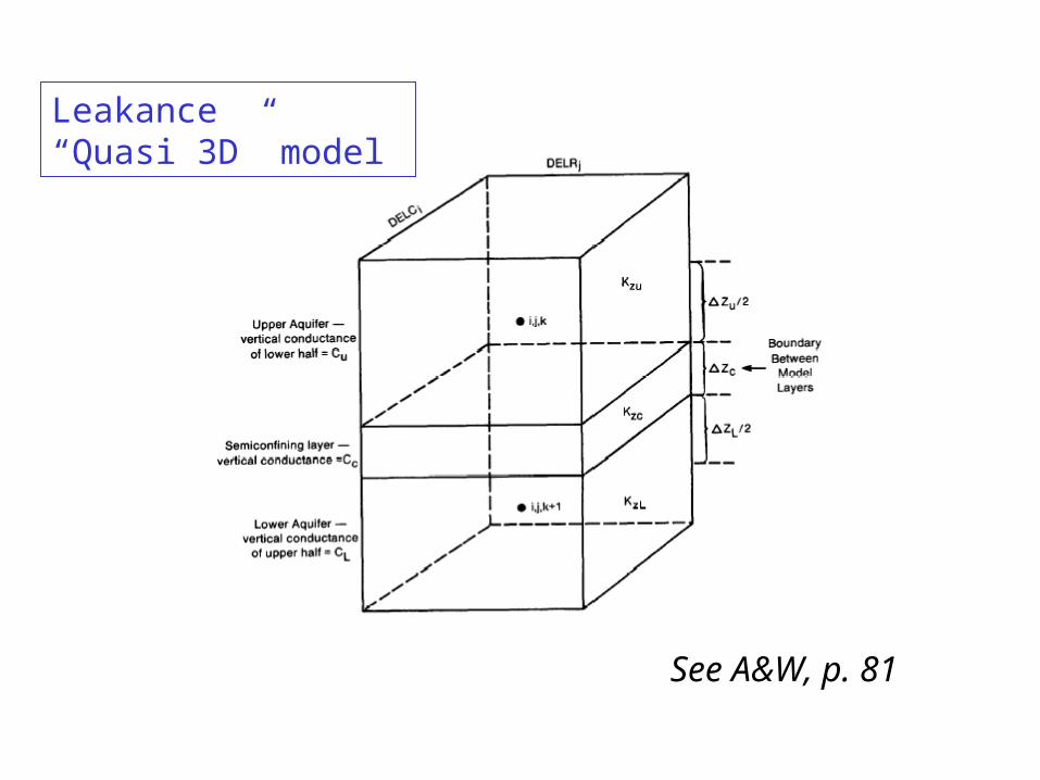
Leakance“Quasi 3D” model
See A&W, p. 81
980
1000
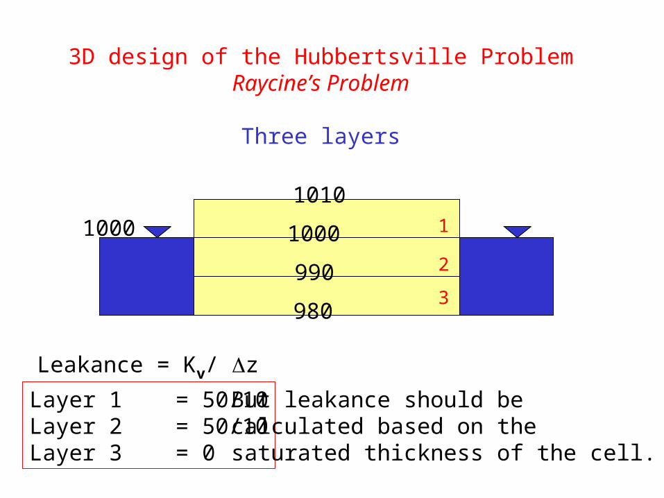
3D design of the Hubbertsville ProblemRaycine’s Problem
Three layers
1000
Leakance = Kv/ z
1
2
3
Layer 1 = 50/10Layer 2 = 50/10Layer 3 = 0
990
But leakance should becalculated based on thesaturated thickness of the cell.
1010
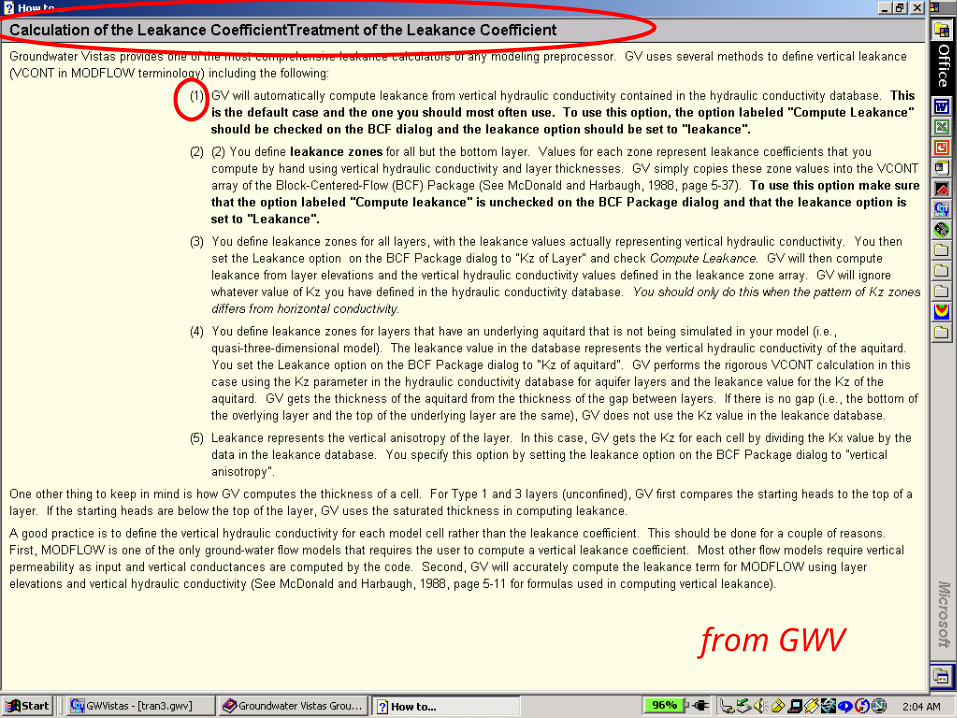
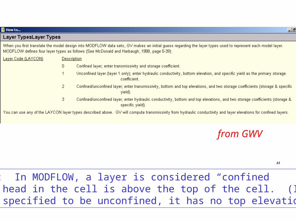
from GWV
from GWV
Remember: In MODFLOW, a layer is considered “confined”when the head in the cell is above the top of the cell. (If the toplayer is specified to be unconfined, it has no top elevation.)
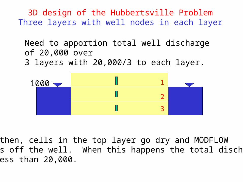
3D design of the Hubbertsville ProblemThree layers with well nodes in each layer
1000 1
2
3
Need to apportion total well discharge of 20,000 over3 layers with 20,000/3 to each layer.
But then, cells in the top layer go dry and MODFLOWshuts off the well. When this happens the total dischargeis less than 20,000.
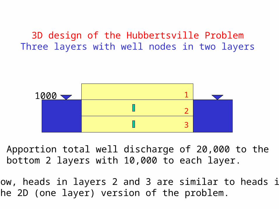
3D design of the Hubbertsville ProblemThree layers with well nodes in two layers
1000 1
2
3
Apportion total well discharge of 20,000 to the bottom 2 layers with 10,000 to each layer.
Now, heads in layers 2 and 3 are similar to heads inthe 2D (one layer) version of the problem.


![A Dimension-reduced Pressure Solver for Liquid Simulations · dimension-reduction techniques and clever changes of ba-sis [TLP06,DWLF12]. Unfortunately, these previous tech-niques](https://img.pdfslide.us/doc/110x75/6035e0c7f2eaa84d7b77da38/a-dimension-reduced-pressure-solver-for-liquid-simulations-dimension-reduction-techniques.jpg)