Embed Size (px)
Citation preview
3D Manufacturing Format Specification and Reference Guide 1
Copyright 3MF Consortium 2015
3D Manufacturing Format
Core Specification & Reference Guide
Version 1.0
Status Published
THESE MATERIALS ARE PROVIDED “AS IS.” The contributors expressly disclaim any warranties (express, implied, or otherwise),
including implied warranties of merchantability, non-infringement, fitness for a particular purpose, or title, related to the
materials. The entire risk as to implementing or otherwise using the materials is assumed by the implementer and user. IN NO
EVENT WILL ANY MEMBER BE LIABLE TO ANY OTHER PARTY FOR LOST PROFITS OR ANY FORM OF INDIRECT, SPECIAL, INCIDENTAL,
OR CONSEQUENTIAL DAMAGES OF ANY CHARACTER FROM ANY CAUSES OF ACTION OF ANY KIND WITH RESPECT TO THIS
DELIVERABLE OR ITS GOVERNING AGREEMENT, WHETHER BASED ON BREACH OF CONTRACT, TORT (INCLUDING NEGLIGENCE),
OR OTHERWISE, AND WHETHER OR NOT THE OTHER MEMBER HAS BEEN ADVISED OF THE POSSIBILITY OF SUCH DAMAGE.
2
Version 1.0 4/29/2015 6:40:00 PM
Table of Contents
Preface .................................................................................................................................. 4
About this Specification ..................................................................................................................4
Document Conventions ..................................................................................................................4
Language Notes ..............................................................................................................................5
Software Conformance ...................................................................................................................5
Part I. 3MF Documents .......................................................................................................... 7
Chapter 1. 3MF Document Format ......................................................................................... 8
1.1. How This Specification Is Organized .....................................................................................8
1.2. Package ..............................................................................................................................9
Chapter 2. Parts and Relationships ...................................................................................... 10
2.1. 3D Payload ........................................................................................................................ 10
2.1.1. 3D Parts and Payload Relationships .................................................................................... 10
2.1.2. 3D Model Part ..................................................................................................................... 12
2.1.3. Thumbnail Part .................................................................................................................... 12
2.1.4. PrintTicket Part ................................................................................................................... 13
2.2. Part Naming Recommendations ........................................................................................ 13
2.3. 3MF Document Markup ..................................................................................................... 14
2.3.1. Support for Versioning and Extensibility ............................................................................ 14
2.3.2. XML Usage ........................................................................................................................... 15
2.3.3. Markup Model .................................................................................................................... 15
2.3.4. Whitespace ......................................................................................................................... 15
2.3.5. Language ............................................................................................................................. 16
Chapter 3. 3D Models .......................................................................................................... 17
3.1. Coordinate Space .............................................................................................................. 17
3.2. Relative Directions and Measurement ............................................................................... 17
3.3. 3D Matrices....................................................................................................................... 18
3.4. Model ............................................................................................................................... 19
3.4.1. Metadata ............................................................................................................................. 21
3.4.2. Resources ............................................................................................................................ 22
3.4.3. Build Instructions ................................................................................................................ 23
Chapter 4. Object Resources ................................................................................................ 25
4.1. Meshes ............................................................................................................................. 26
4.1.1. Fill Rule ................................................................................................................................ 27
4.1.2. Vertices ............................................................................................................................... 28
4.1.3. Triangles .............................................................................................................................. 29
4.2. Components ..................................................................................................................... 31
4.2.1. Component ......................................................................................................................... 32
3D Manufacturing Format Specification and Reference Guide 3
Copyright 3MF Consortium 2015
Chapter 5. Material Resources ............................................................................................. 33
5.1. Base Material .................................................................................................................... 33
5.1.1. sRGB Color ........................................................................................................................... 34
Chapter 6. 3MF Document Package Features ....................................................................... 35
6.1. Thumbnail ......................................................................................................................... 35
6.1.1. JPEG Images ........................................................................................................................ 35
6.1.2. PNG Images ......................................................................................................................... 35
6.2. Core Properties ................................................................................................................. 36
6.3. Digital Signatures .............................................................................................................. 36
6.3.1. Normalization ...................................................................................................................... 36
6.4. Protected Content ............................................................................................................. 37
Part II. Appendixes .............................................................................................................. 38
Appendix A. Glossary ........................................................................................................... 39
Appendix B. 3MF XSD Schema ............................................................................................. 42
Appendix C. Standard Namespaces and Content Types ........................................................ 46
C.1 Content Types ................................................................................................................... 46
C.2 Relationship Types ............................................................................................................ 46
C.3 Namespaces ...................................................................................................................... 46
References .......................................................................................................................... 47
4
Version 1.0 4/29/2015 6:40:00 PM
Preface
About this Specification
The 3D Manufacturing Format, or 3MF, describes the set of conventions for the use of XML and other
widely available technologies to describe the content and appearance of one or more 3D models. It is
written for developers who are building systems to process 3MF content.
A primary goal of this specification is to ensure the interoperability of independently created software
and hardware systems that produce or consume 3MF content. This specification defines the formal
requirements that producers and consumers must satisfy in order to achieve interoperability.
This specification describes a 3D model and containing format called the 3MF Document. The format
requirements are an extension of the packaging requirements described in the Open Packaging
Conventions specification. That specification describes packaging and physical format conventions for
the use of XML, Unicode, ZIP, and other technologies and specifications to organize the content and
resources that make up any model. They are an integral part of the 3MF specification.
Understanding this specification requires working knowledge of the Extensible Markup Language (XML)
and XML Namespace specifications. Full understanding might also require domain knowledge of
common terms and procedures within the 3D manufacturing sector, although every effort has been
made to minimize such reliance.
The 3MF Consortium offers a free to use open source implementation of this specification in order to
allow an easy adoption of the format in applications handling 3D content.
Part I, “3MF Documents,” presents the details of the primarily XML-based 3MF Document format. This
section describes the XML markup that defines the composition of 3D documents and the appearance of
each model within the document.
Part II, “Appendixes,” contains additional technical details and schemas too extensive to include in the
main body of the text as well as convenient reference information.
The information contained in this specification is subject to change. Every effort has been made to
ensure its accuracy at the time of publication.
Document Conventions
Except where otherwise noted, syntax descriptions are expressed in the ABNF format as defined in RFC
4234.
Glossary terms are formatted like this.
3D Manufacturing Format Specification and Reference Guide 5
Copyright 3MF Consortium 2015
Syntax descriptions and code are formatted in monospace type.
Replaceable items, that is, an item intended to be replaced by a value, are formatted in monospace
cursive type.
Notes are formatted as follows:
Note: This is a note.
Language Notes
In this specification, the words that are used to define the significance of each requirement are written
in uppercase. These words are used in accordance with their definitions in RFC 2119, and their
respective meanings are reproduced below:
MUST. This word, or the adjective “REQUIRED,” means that the item is an absolute requirement
of the specification.
SHOULD. This word, or the adjective “RECOMMENDED,” means that there may exist valid
reasons in particular circumstances to ignore this item, but the full implications should be
understood and the case carefully weighed before choosing a different course.
MAY. This word, or the adjective “OPTIONAL,” means that this item is truly optional. For
example, one implementation may choose to include the item because a particular marketplace
or scenario requires it or because it enhances the product. Another implementation may omit
the same item.
Software Conformance
Most requirements are expressed as format or package requirements rather than implementation
requirements.
In order for consumers to be considered conformant, they must observe the following rules:
They MUST NOT report errors when processing conforming instances of the document format
except when forced to do so by resource exhaustion.
They SHOULD report errors when processing non-conforming instances of the document format
when doing so does not pose an undue processing or performance burden.
In order for producers to be considered conformant, they must observe the following rules:
They MUST NOT generate any new, non-conforming instances of the document format.
They MUST NOT introduce any non-conformance when modifying an instance of the document
format.

6
Version 1.0 4/29/2015 6:40:00 PM
Editing applications are subject to all of the above rules.
3D Manufacturing Format Specification and Reference Guide 7
Copyright 3MF Consortium 2015
PART I. 3MF DOCUMENTS
8
Version 1.0 4/29/2015 6:40:00 PM
Chapter 1. 3MF Document Format
This specification describes how the 3MF Document format is organized internally and realized in 3D
objects externally. It can be used as a stand-alone file format or as a payload in a print pipeline. It is built
upon the principles described in the Open Packaging Conventions specification. 3MF Documents MUST
observe all requirements and recommendations of that specification, except where indicated otherwise
in this specification. The information presented here is intended both for producers, which emit content
in the 3MF Document format, and consumers, which access and transform into 3D objects the contents
of a 3MF document. An editor is an entity that acts as both a producer and a consumer of content in the
3MF Document format. A manufacturing device is a consumer that produces a physical part.
The 3MF Document format represents a 3D model, or a representation of one or more physical object
descriptions in a markup format. A file that implements this format includes the fundamental
information necessary for a consumer to generate a physical object through additive manufacturing or
basic subtractive manufacturing techniques. This includes resources such as textures that might be
required to reproduce the exact desired appearance in terms of color or internal structures in terms of
materials.
This format also includes optional components that build on the minimal set of components required to
generate a physical object. This includes the ability to specify print job control instructions, to describe
assembly of objects intended to be generated simultaneously in an interlocked or disjoint manner,
among others.
Finally, the 3MF Document format implements the common package features specified by the Open
Packaging Conventions specification that support digital signatures and core properties.
1.1. How This Specification Is Organized
Chapter Description
3MF Document Format
Introduction to the 3MF Document file format and overview of basic package requirements.
Parts and Relationships
Describes the Open Packaging Convention package parts and relationships in a 3MF Document.
3D Models Introduces the primary organization of a 3MF Document into resources and build instructions.
Objects This chapter describes how objects are defined by a triangular mesh.
Materials This chapter provides detailed information about how material resources are defined. These resources are used in turn by objects to complete a 3D object definition.
Package Features Describes the 3MF Document features provided by the Open Packaging Conventions, including thumbnails, digital signatures, and core properties and protected content.
Glossary A full summary and definition of all glossary terms introduced in this specification.
3D Manufacturing Format Specification and Reference Guide 9
Copyright 3MF Consortium 2015
XSD Schema The schema for the 3D Model part.
Standard Namespaces & Content Types
A reference on the standard namespaces and content types for 3MF Documents.
1.2. Package
The 3MF Document format MUST use a ZIP archive for its physical model. The Open Packaging
specification describes a packaging model, that is, how the package is represented internally with parts
and relationships.
The 3MF Document format includes a well-defined set of parts and relationships, each fulfilling a
particular purpose in the document. The format also extends the package features, including digital
signatures and thumbnails.
10
Version 1.0 4/29/2015 6:40:00 PM
Chapter 2. Parts and Relationships
The packaging conventions described in the Open Packaging Conventions (OPC) specification can be
used to carry any payload. A payload is a complete collection of interdependent parts and relationships
within a package. This specification defines a particular payload that contains a 3D object definition and
its supporting files: the 3D payload.
An OPC package that holds a 3D payload and follows the rules described in this specification is referred
to as a 3MF Document. Producers and consumers of 3MF Documents can implement their own parsers
and manufacturing devices based on this specification.
2.1. 3D Payload
A payload that has a 3D Model root part is known as a 3D payload. There can be more than one 3D
payload in a 3MF Document, but only one primary 3D payload.
2.1.1. 3D Parts and Payload Relationships
A specific relationship type is defined to identify the root of a 3D payload within a 3MF Document: the
3MF Document StartPart relationship. The primary 3D payload root is the 3D Model part that is
referenced by the 3MF Document StartPart relationship to find the primary 3D payload in a package.
The 3MF Document StartPart relationship MUST point to the 3D Model part that identifies the root of
the 3D payload.
The payload includes the full set of parts required for processing the 3D Model part. All content to be
used to manufacture an object described in the 3D payload MUST be contained in the 3MF Document.
The parts that can be found in a 3MF Document are listed in Table 2–1. Relationships and content types
for these parts are defined in Appendix C, “Standard Namespaces and Content Types.” Each part MUST
use only the appropriate content type specified in Appendix C.
Parts included to the 3D payload are explicitly linked to the 3D payload root by relationship. 3MF
Documents MUST NOT reference resources external to the 3MF Document package unless specified
otherwise in an extension. For more information on relationships, see the Open Packaging Conventions
specification.
Parts in the 3D payload MUST use one of the appropriate relationships described below to establish that
relationship between two parts in the payload. There MUST NOT be more than one relationship of a
given relationship type from one part to a second part. Relationship types are defined in Appendix C,
“Standard Namespaces and Content Types.”
Producers that generate a relationship MUST include the target part in the 3MF Document for any of the
following relationship types: PrintTicket, StartPart, and Thumbnail. Consumers that access the target
3D Manufacturing Format Specification and Reference Guide 11
Copyright 3MF Consortium 2015
part of any relationship with one of these relationship types MUST generate an error if the part is not
included in the 3MF Document.
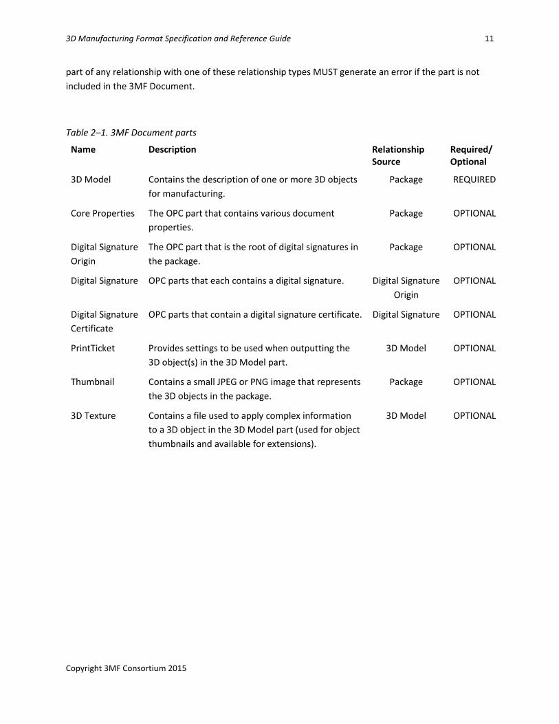
Table 2–1. 3MF Document parts
Name Description Relationship Source
Required/Optional
3D Model Contains the description of one or more 3D objects
for manufacturing.
Package REQUIRED
Core Properties The OPC part that contains various document
properties.
Package OPTIONAL
Digital Signature
Origin
The OPC part that is the root of digital signatures in
the package.
Package OPTIONAL
Digital Signature OPC parts that each contains a digital signature. Digital Signature
Origin
OPTIONAL
Digital Signature
Certificate
OPC parts that contain a digital signature certificate. Digital Signature OPTIONAL
PrintTicket Provides settings to be used when outputting the
3D object(s) in the 3D Model part.
3D Model OPTIONAL
Thumbnail Contains a small JPEG or PNG image that represents
the 3D objects in the package.
Package OPTIONAL
3D Texture Contains a file used to apply complex information
to a 3D object in the 3D Model part (used for object
thumbnails and available for extensions).
3D Model OPTIONAL
12
Version 1.0 4/29/2015 6:40:00 PM
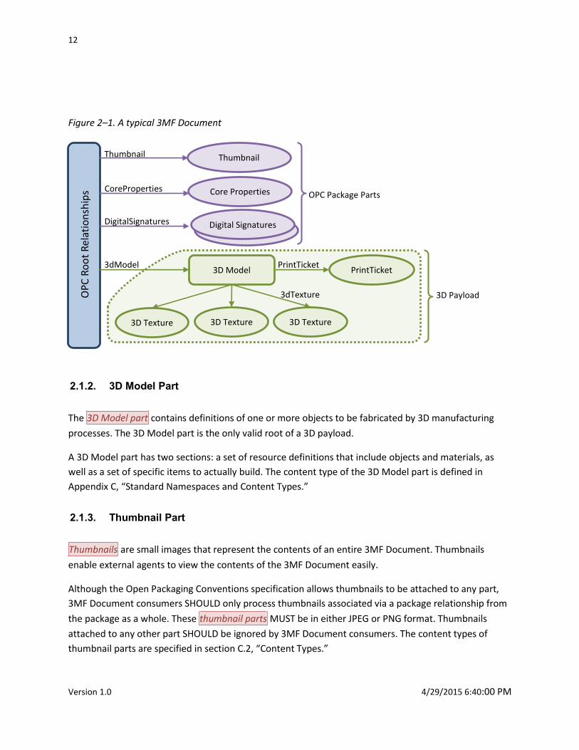
Figure 2–1. A typical 3MF Document
2.1.2. 3D Model Part
The 3D Model part contains definitions of one or more objects to be fabricated by 3D manufacturing
processes. The 3D Model part is the only valid root of a 3D payload.
A 3D Model part has two sections: a set of resource definitions that include objects and materials, as
well as a set of specific items to actually build. The content type of the 3D Model part is defined in
Appendix C, “Standard Namespaces and Content Types.”
2.1.3. Thumbnail Part
Thumbnails are small images that represent the contents of an entire 3MF Document. Thumbnails
enable external agents to view the contents of the 3MF Document easily.
Although the Open Packaging Conventions specification allows thumbnails to be attached to any part,
3MF Document consumers SHOULD only process thumbnails associated via a package relationship from
the package as a whole. These thumbnail parts MUST be in either JPEG or PNG format. Thumbnails
attached to any other part SHOULD be ignored by 3MF Document consumers. The content types of
thumbnail parts are specified in section C.2, “Content Types.”
OP
C R
oo
t R
elat
ion
ship
s
3dModel PrintTicket
CoreProperties
DigitalSignatures
Core Properties
Digital Signatures
3D Model PrintTicket
3D Texture 3D Texture 3D Texture
3D Payload
OPC Package Parts
3dTexture
Thumbnail Thumbnail
3D Manufacturing Format Specification and Reference Guide 13
Copyright 3MF Consortium 2015
For more information about the relationship type for thumbnail parts, see section C.3, “Relationship
Types.”
2.1.4. PrintTicket Part
PrintTicket parts provide user intent and device configuration information to printing consumers. A
PrintTicket part can be attached only to a 3D Model part and each 3D Model part MUST attach no more
than one PrintTicket. The PrintTicket format is governed by the specific consumer environment. For
example, for printing on Microsoft Windows, valid PrintTicket settings are specified in the Print Schema
Keywords for 3D Manufacturing specification.
If no PrintTicket is provided or the PrintTicket provided is not supported by the consumer, it is left to the
consumer to apply its own defaults.
2.2. Part Naming Recommendations
Producers and consumers of 3MF Documents refer to parts by name and use relationship names to
identify the purpose of related parts. The Open Packaging Conventions specification describes the
syntax for part name. However, following these rules alone can result in a package that is difficult for
users to understand. For example, a user would have to open every Relationship part to know which
parts are necessary to accurately manufacture a 3MF Document.
By choosing part names according to a well-defined, human-readable convention, the resulting package
is easier to browse and specific parts are more easily located. Part names MUST still conform to the
syntax specified in the Open Packaging Conventions specification.
It is RECOMMENDED that producers of 3MF Documents use the following part naming convention:
The 3D Model part name SHOULD contain two segments, the first being “/3D/” and the second
with the extension “.model” on the last segment, for example “/3D/3dModel.model”.
The PrintTicket part name SHOULD be associated via relationship with the 3D Model part and
contains three segments, using “/3D/Metadata/” as the first two segments with the extension
“.xml”. For example, “/3D/Metadata/Model_PT.xml”.
3D Texture part names SHOULD contain three segments, using “/3D/Textures/” as the first two
segments, for example “/3D/Textures/coloring.png”. 3D Texture parts MUST be associated with
the 3D Model part via relationship.
The names of any non-standard parts that are associated with the 3D payload SHOULD contain 3
segments, using “/3D/Other/” as the first two segments.
14
Version 1.0 4/29/2015 6:40:00 PM
2.3. 3MF Document Markup
3MF Document markup has been designed to facilitate independent development of compatible
systems that produce or consume 3MF Documents.
The design of 3MF Document markup reflects the tradeoffs between two, sometimes competing, goals:
1. 3MF Document markup should be parsimonious; that is, it should include only the minimum set
of primitive operations and markup constructs necessary to manufacture common 3D objects
with full fidelity. Redundancy in the specification increases the opportunity for independent
implementations to introduce accidental incompatibilities. Redundancy also increases the cost
of implementation and testing, and, typically, the required memory component.
2. 3MF Document markup should be compact; that is, the most common primitives should have
compact representations. Bloated representations compromise the performance of systems
handling 3MF Documents. As byte-count increases, so does communication time. Although
compression can be used to improve communication time, it cannot eliminate the performance
loss caused by bloated representations.
2.3.1. Support for Versioning and Extensibility
3MF Document markup has been designed in anticipation of the evolution of this specification. It also
allows third parties to extend the markup.
Extensions are a critical part of 3MF, and as such, this core specification is as narrow as possible.
Advanced features are built as extensions, using an a la carte model whereby producers can state
explicitly which extensions are used (by declaring the matching XML namespace in the <model>
element) and consumers can state explicitly which extensions they support, so other tools in the chain
know which parts will be ignored. Versioning is accomplished concurrently, as the namespace will be
updated to reflect a version change. Therefore versioning happens independently for the core spec and
for each extension, and the version of each can be determined by checking its namespace.
Extension specifications MUST include one or more targeted versions of this core specification to limit
the number of possible configurations. Producers can specify certain extensions as required in a
particular 3MF document, in which case consumers that do not support those extensions MUST fail to
edit or manufacture that document, rather than ignoring the extension namespace.
Within this core XSD schema (see Appendix B: 3MF XSD Schema), extension points have been explicitly
entered in the form of <any> elements and <anyAttribute> (also visible in the element diagrams further
along in this specification). These are required to come from other namespaces, which SHOULD point to
a way to find the appropriate specification and accompanying XSD schema.
3D Manufacturing Format Specification and Reference Guide 15
Copyright 3MF Consortium 2015
2.3.2. XML Usage
All XML content of the parts defined in this specification MUST conform to the following validation rules:
1. XML content MUST be encoded using either UTF-8 or UTF-16. If any such part includes an
encoding declaration (as defined in Section 4.3.3 of the XML specification), that declaration
MUST NOT name any encoding other than UTF-8 or UTF-16.
2. The XML 1.0 specification allows for the usage of Data Type Definitions (DTDs), which enabled
denial of service attacks, typically through the use of an internal entity expansion technique. As
mitigation for this potential threat, DTD content MUST NOT be used in the XML markup defined
in this specification, and consumers SHOULD treat the presence of DTD content as an error.
3. XML content MUST be valid against the corresponding XSD schema defined in this specification.
In particular, the XML content MUST NOT contain elements or attributes drawn from
namespaces that are not explicitly defined in the corresponding XSD unless the XSD allows
elements or attributes drawn from any namespace to be present in particular locations in the
XML markup.
4. XML content MUST NOT contain elements or attributes drawn from the “xml” or “xsi”
namespaces unless they are explicitly defined in the XSD schema or by other means in the
specification.
5. XML content MUST be produced and parsed with the en-us locale, particularly with respect to
values containing decimal data.
2.3.3. Markup Model
3MF Document markup is an XML-based markup language that uses elements, attributes, and
namespaces. The schema for 3MF Document markup includes only elements and their attributes,
comments, and whitespace.
2.3.3.1. XML Namespaces
The 3MF Document core XML namespace, the principal namespace used for elements and attributes in
3D Model part markup is given in Appendix C, “Standard Namespaces and Content Types”. Any elements
and attributes undefined in this spec must be prefaced with the namespace corresponding to the 3MF
extension they belong to.
2.3.4. Whitespace
3MF Documents allow flexible whitespace usage in markup. Wherever a single whitespace character is
allowed, multiple whitespace characters MAY be used. 3MF Document markup MUST NOT use the
xml:space attribute. Additionally, where the 3MF Document schema specifies attributes of types that
allow whitespace collapsing, leading and trailing whitespace in the attribute value MAY be used along
16
Version 1.0 4/29/2015 6:40:00 PM
with other whitespace that relies on the whitespace collapsing behavior specified in the XML Schema
Specification.
Note: Consult the 3MF Schema for exact whitespace allowed.
2.3.5. Language
The language of the contents of a 3MF Document (typically useful for content provided in metadata)
MAY be identified using the xml:lang attribute, the value of which is inherited by child and descendant
elements. This attribute is defined in the W3C XML specification. When the language of the contents is
unknown, the value “und” (undetermined) MUST be used.
3D Manufacturing Format Specification and Reference Guide 17
Copyright 3MF Consortium 2015
Chapter 3. 3D Models
The model, in this specification, refers to the object or objects to be created via 3D manufacturing
processes as a single operation. It might include a single object, multiple homogenous objects, multiple
heterogeneous objects, an object fully enclosed in another object, or multiple objects in an interlocked
and inseparable assembly.
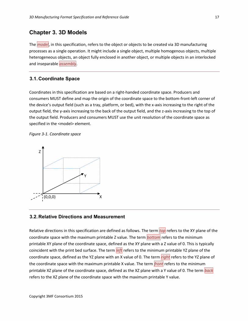
3.1. Coordinate Space
Coordinates in this specification are based on a right-handed coordinate space. Producers and
consumers MUST define and map the origin of the coordinate space to the bottom-front-left corner of
the device’s output field (such as a tray, platform, or bed), with the x-axis increasing to the right of the
output field, the y-axis increasing to the back of the output field, and the z-axis increasing to the top of
the output field. Producers and consumers MUST use the unit resolution of the coordinate space as
specified in the <model> element.
Figure 3-1. Coordinate space
3.2. Relative Directions and Measurement
Relative directions in this specification are defined as follows. The term top refers to the XY plane of the
coordinate space with the maximum printable Z value. The term bottom refers to the minimum
printable XY plane of the coordinate space, defined as the XY plane with a Z value of 0. This is typically
coincident with the print bed surface. The term left refers to the minimum printable YZ plane of the
coordinate space, defined as the YZ plane with an X value of 0. The term right refers to the YZ plane of
the coordinate space with the maximum printable X value. The term front refers to the minimum
printable XZ plane of the coordinate space, defined as the XZ plane with a Y value of 0. The term back
refers to the XZ plane of the coordinate space with the maximum printable Y value.
Z
Y
X
(0,0,0) X
18
Version 1.0 4/29/2015 6:40:00 PM
These terms might also be applied to models, in which case they are defined relative to the bounding
box of the model when transformed to the coordinate space defined in this specification.
Producers and consumers MUST interpret coordinates in relation to the coordinate space defined in this
specification.
3.3. 3D Matrices
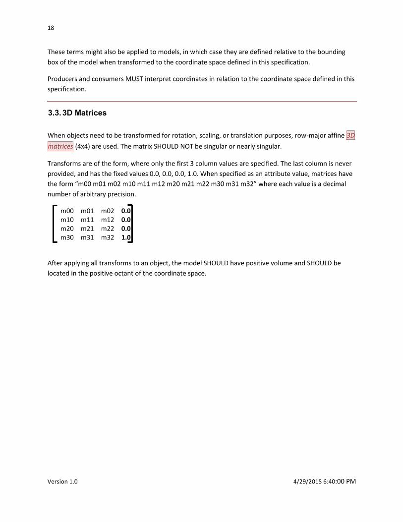
When objects need to be transformed for rotation, scaling, or translation purposes, row-major affine 3D
matrices (4x4) are used. The matrix SHOULD NOT be singular or nearly singular.
Transforms are of the form, where only the first 3 column values are specified. The last column is never
provided, and has the fixed values 0.0, 0.0, 0.0, 1.0. When specified as an attribute value, matrices have
the form “m00 m01 m02 m10 m11 m12 m20 m21 m22 m30 m31 m32” where each value is a decimal
number of arbitrary precision.
m00 m01 m02 0.0 m10 m11 m12 0.0 m20 m21 m22 0.0 m30 m31 m32 1.0
After applying all transforms to an object, the model SHOULD have positive volume and SHOULD be
located in the positive octant of the coordinate space.
3D Manufacturing Format Specification and Reference Guide 19
Copyright 3MF Consortium 2015
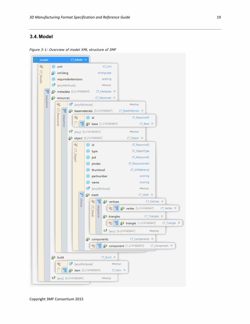
3.4. Model
Figure 3-1: Overview of model XML structure of 3MF
20
Version 1.0 4/29/2015 6:40:00 PM
This XML specification is designed to be used with a simple, forward only parser, and the element
ordering defined supports this. Producers MUST define each element prior to referencing it elsewhere in
the document, unless specifically allowed by an extension.
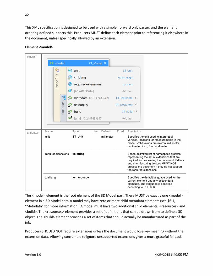
Element <model>
diagram
attributes Name Type Use Default Fixed Annotation
unit ST_Unit millimeter Specifies the unit used to interpret all
vertices, locations, or measurements in the model. Valid values are micron, millimeter, centimeter, inch, foot, and meter.
requiredextensions xs:string Space-delimited list of namespace prefixes, representing the set of extensions that are required for processing the document. Editors and manufacturing devices MUST NOT process the document if they do not support the required extensions.
xml:lang xs:language Specifies the default language used for the
current element and any descendant elements. The language is specified according to RFC 3066.
The <model> element is the root element of the 3D Model part. There MUST be exactly one <model>
element in a 3D Model part. A model may have zero or more child metadata elements (see §6.1,
"Metadata" for more information). A model must have two additional child elements: <resources> and
<build>. The <resources> element provides a set of definitions that can be drawn from to define a 3D
object. The <build> element provides a set of items that should actually be manufactured as part of the
job.
Producers SHOULD NOT require extensions unless the document would lose key meaning without the
extension data. Allowing consumers to ignore unsupported extensions gives a more graceful fallback.
3D Manufacturing Format Specification and Reference Guide 21
Copyright 3MF Consortium 2015
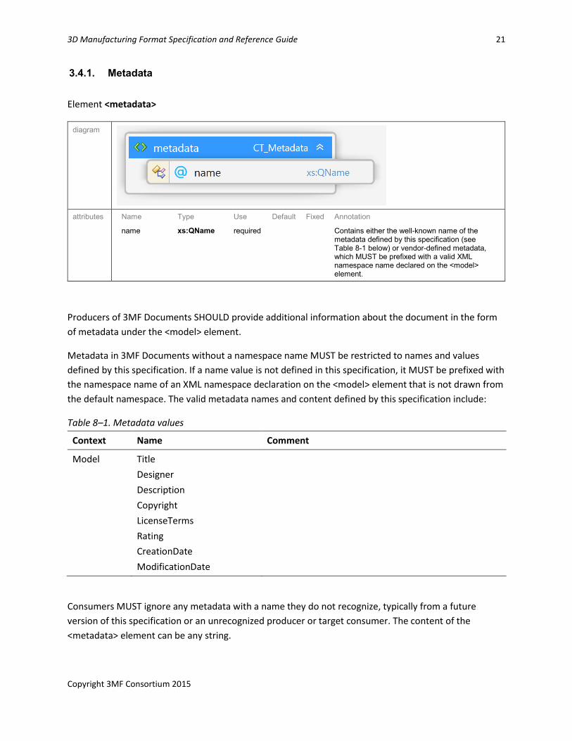
3.4.1. Metadata
Element <metadata>
diagram
attributes Name Type Use Default Fixed Annotation
name xs:QName required Contains either the well-known name of the metadata defined by this specification (see Table 8-1 below) or vendor-defined metadata, which MUST be prefixed with a valid XML namespace name declared on the <model> element.
Producers of 3MF Documents SHOULD provide additional information about the document in the form
of metadata under the <model> element.
Metadata in 3MF Documents without a namespace name MUST be restricted to names and values
defined by this specification. If a name value is not defined in this specification, it MUST be prefixed with
the namespace name of an XML namespace declaration on the <model> element that is not drawn from
the default namespace. The valid metadata names and content defined by this specification include:
Table 8–1. Metadata values
Context Name Comment
Model Title
Designer
Description
Copyright
LicenseTerms
Rating
CreationDate
ModificationDate
Consumers MUST ignore any metadata with a name they do not recognize, typically from a future
version of this specification or an unrecognized producer or target consumer. The content of the
<metadata> element can be any string.
22
Version 1.0 4/29/2015 6:40:00 PM
A consumer that wishes to receive additional information using this mechanism SHOULD publish a
namespace URI and a set of well-defined metadata names and expected content in order for producers
to generate content in an expected fashion.
Producers MUST NOT create multiple metadata elements with the same name.
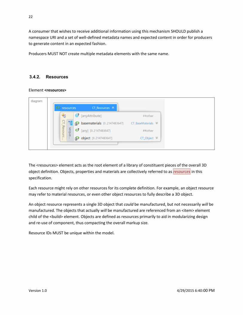
3.4.2. Resources
Element <resources>
diagram
The <resources> element acts as the root element of a library of constituent pieces of the overall 3D
object definition. Objects, properties and materials are collectively referred to as resources in this
specification.
Each resource might rely on other resources for its complete definition. For example, an object resource
may refer to material resources, or even other object resources to fully describe a 3D object.
An object resource represents a single 3D object that could be manufactured, but not necessarily will be
manufactured. The objects that actually will be manufactured are referenced from an <item> element
child of the <build> element. Objects are defined as resources primarily to aid in modularizing design
and re-use of component, thus compacting the overall markup size.
Resource IDs MUST be unique within the model.
3D Manufacturing Format Specification and Reference Guide 23
Copyright 3MF Consortium 2015
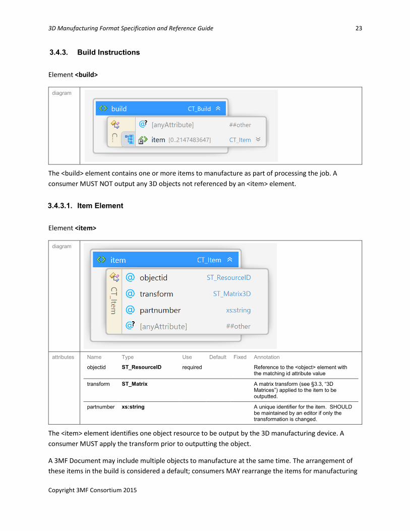
3.4.3. Build Instructions
Element <build>
diagram
The <build> element contains one or more items to manufacture as part of processing the job. A
consumer MUST NOT output any 3D objects not referenced by an <item> element.
3.4.3.1. Item Element
Element <item>
diagram
attributes Name Type Use Default Fixed Annotation
objectid ST_ResourceID required Reference to the <object> element with the matching id attribute value
transform ST_Matrix A matrix transform (see §3.3, “3D
Matrices”) applied to the item to be outputted.
partnumber xs:string A unique identifier for the item. SHOULD be maintained by an editor if only the transformation is changed.
The <item> element identifies one object resource to be output by the 3D manufacturing device. A
consumer MUST apply the transform prior to outputting the object.
A 3MF Document may include multiple objects to manufacture at the same time. The arrangement of
these items in the build is considered a default; consumers MAY rearrange the items for manufacturing
24
Version 1.0 4/29/2015 6:40:00 PM
in order to better pack the build volume. Sometimes objects are arranged in the coordinate space so as
to be manufactured in an interlocking fashion; producers of these objects SHOULD collect them as
components (see §4.2, “Components”), as 3D manufacturing devices MUST NOT transform components
of an object relative to each other.
If the items overlap, 3D manufacturing devices MUST use the Positive fill rule (described in section 4.1.1)
to resolve the ambiguity. To avoid this, 3D manufacturing devices SHOULD NOT allow items to overlap
when packing the build volume.
Note: items must not reference objects of type “other”
3D Manufacturing Format Specification and Reference Guide 25
Copyright 3MF Consortium 2015
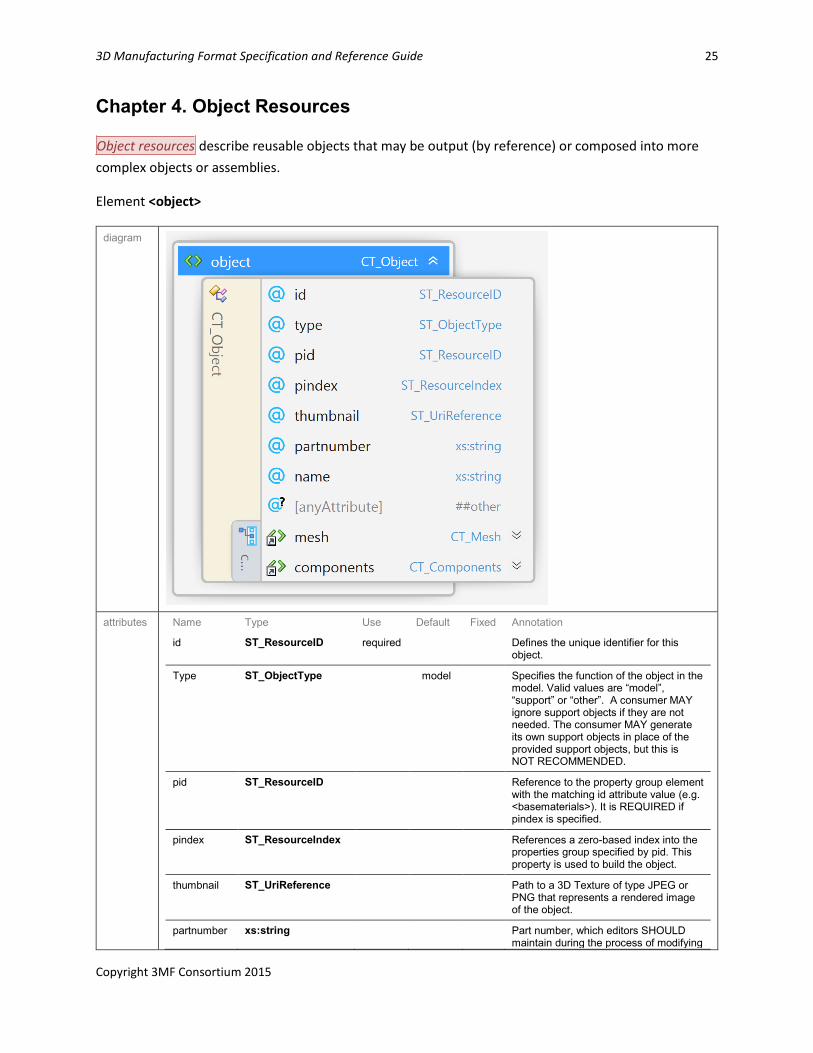
Chapter 4. Object Resources
Object resources describe reusable objects that may be output (by reference) or composed into more
complex objects or assemblies.
Element <object>
diagram
attributes Name Type Use Default Fixed Annotation
id ST_ResourceID required Defines the unique identifier for this object.
Type ST_ObjectType model Specifies the function of the object in the
model. Valid values are “model”, “support” or “other”. A consumer MAY ignore support objects if they are not needed. The consumer MAY generate its own support objects in place of the provided support objects, but this is NOT RECOMMENDED.
pid ST_ResourceID Reference to the property group element with the matching id attribute value (e.g. <basematerials>). It is REQUIRED if pindex is specified.
pindex ST_ResourceIndex References a zero-based index into the properties group specified by pid. This property is used to build the object.
thumbnail ST_UriReference Path to a 3D Texture of type JPEG or PNG that represents a rendered image of the object.
partnumber xs:string Part number, which editors SHOULD maintain during the process of modifying
26
Version 1.0 4/29/2015 6:40:00 PM
and deriving objects.
name xs:string Name of object to improve readability.
An object resource is defined by an <object> element. An <object> element has attributes for the
property group and specific property member that are to be applied to the entire object, except where
overridden by a descendant element, such as a <triangle> element or a component-referenced <object>
element. If this object contains any triangles with assigned materials, the object MUST specify pid and
pindex, to act as default values for any triangles with unspecified properties. If no properties are
assigned at all, the choice for the properties of the object is left to the consumer.
The object type is ignored on objects that contain components, since the type is always overridden by
descendant objects.
Object thumbnails MUST have an appropriate 3D Texture relationship to the model part as described in
section 2.1.1.
Part numbers are intended as a way to keep track of objects which may have been modified during a
tool chain. When editing or processing a 3MF document, these part numbers SHOULD be preserved to
the greatest degree possible, duplicating them for objects split into pieces, removing them from objects
that are combined, and maintaining them for objects that are modified.
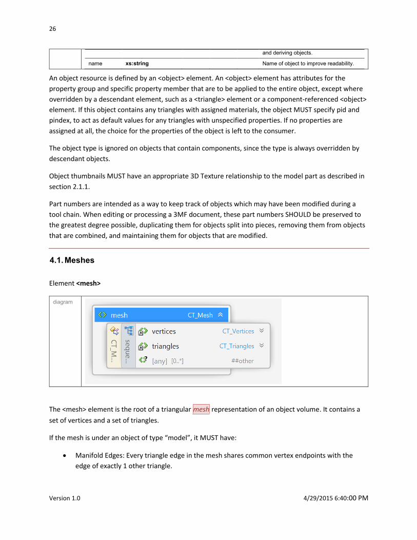
4.1. Meshes
Element <mesh>
diagram
The <mesh> element is the root of a triangular mesh representation of an object volume. It contains a
set of vertices and a set of triangles.
If the mesh is under an object of type “model”, it MUST have:
Manifold Edges: Every triangle edge in the mesh shares common vertex endpoints with the
edge of exactly 1 other triangle.
3D Manufacturing Format Specification and Reference Guide 27
Copyright 3MF Consortium 2015
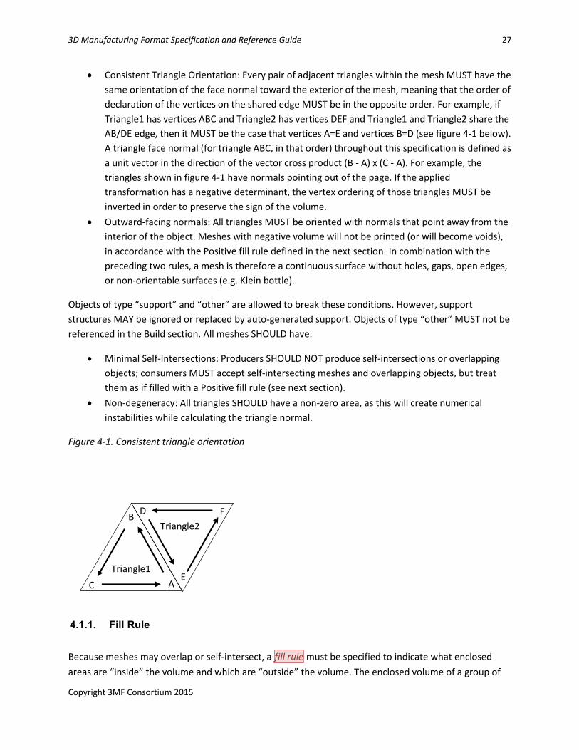
Consistent Triangle Orientation: Every pair of adjacent triangles within the mesh MUST have the
same orientation of the face normal toward the exterior of the mesh, meaning that the order of
declaration of the vertices on the shared edge MUST be in the opposite order. For example, if
Triangle1 has vertices ABC and Triangle2 has vertices DEF and Triangle1 and Triangle2 share the
AB/DE edge, then it MUST be the case that vertices A=E and vertices B=D (see figure 4-1 below).
A triangle face normal (for triangle ABC, in that order) throughout this specification is defined as
a unit vector in the direction of the vector cross product (B - A) x (C - A). For example, the
triangles shown in figure 4-1 have normals pointing out of the page. If the applied
transformation has a negative determinant, the vertex ordering of those triangles MUST be
inverted in order to preserve the sign of the volume.
Outward-facing normals: All triangles MUST be oriented with normals that point away from the
interior of the object. Meshes with negative volume will not be printed (or will become voids),
in accordance with the Positive fill rule defined in the next section. In combination with the
preceding two rules, a mesh is therefore a continuous surface without holes, gaps, open edges,
or non-orientable surfaces (e.g. Klein bottle).
Objects of type “support” and “other” are allowed to break these conditions. However, support
structures MAY be ignored or replaced by auto-generated support. Objects of type “other” MUST not be
referenced in the Build section. All meshes SHOULD have:
Minimal Self-Intersections: Producers SHOULD NOT produce self-intersections or overlapping
objects; consumers MUST accept self-intersecting meshes and overlapping objects, but treat
them as if filled with a Positive fill rule (see next section).
Non-degeneracy: All triangles SHOULD have a non-zero area, as this will create numerical
instabilities while calculating the triangle normal.
Figure 4-1. Consistent triangle orientation
4.1.1. Fill Rule
Because meshes may overlap or self-intersect, a fill rule must be specified to indicate what enclosed
areas are “inside” the volume and which are “outside” the volume. The enclosed volume of a group of
A E
C
B D F
Triangle1
Triangle2
28
Version 1.0 4/29/2015 6:40:00 PM
meshes is defined by applying the fill algorithm. Fill algorithms determine how the intersecting areas of
geometric shapes are combined to form a region. A fill rule is defined identically in 2D as in 3D, so the
examples here will show the 2D equivalent for simplicity of figures. Consumers MAY take advantage of
this fact by applying the fill rule after slicing, thereby simplifying the algorithm by only having to operate
in 2D. By convention, a 2D figure has positive area when wound counter-clockwise, so when looking
along an edge, the local “outside” is to the right, equivalent to the local “outside” of a triangle being the
direction of the normal.
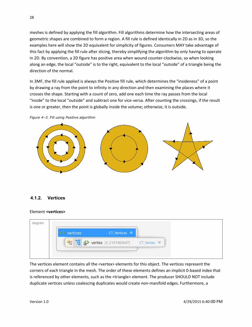
In 3MF, the fill rule applied is always the Positive fill rule, which determines the "insideness" of a point
by drawing a ray from the point to infinity in any direction and then examining the places where it
crosses the shape. Starting with a count of zero, add one each time the ray passes from the local
“inside” to the local “outside” and subtract one for vice-versa. After counting the crossings, if the result
is one or greater, then the point is globally inside the volume; otherwise, it is outside.
Figure 4–3. Fill using Positive algorithm
4.1.2. Vertices
Element <vertices>
diagram
The vertices element contains all the <vertex> elements for this object. The vertices represent the
corners of each triangle in the mesh. The order of these elements defines an implicit 0-based index that
is referenced by other elements, such as the <triangle> element. The producer SHOULD NOT include
duplicate vertices unless coalescing duplicates would create non-manifold edges. Furthermore, a
3D Manufacturing Format Specification and Reference Guide 29
Copyright 3MF Consortium 2015
producer SHOULD collapse vertices that are very closely proximal with a single vertex whenever
appropriate. In order to avoid integer overflows, a vertex array MUST contain less than 2^31 vertices.
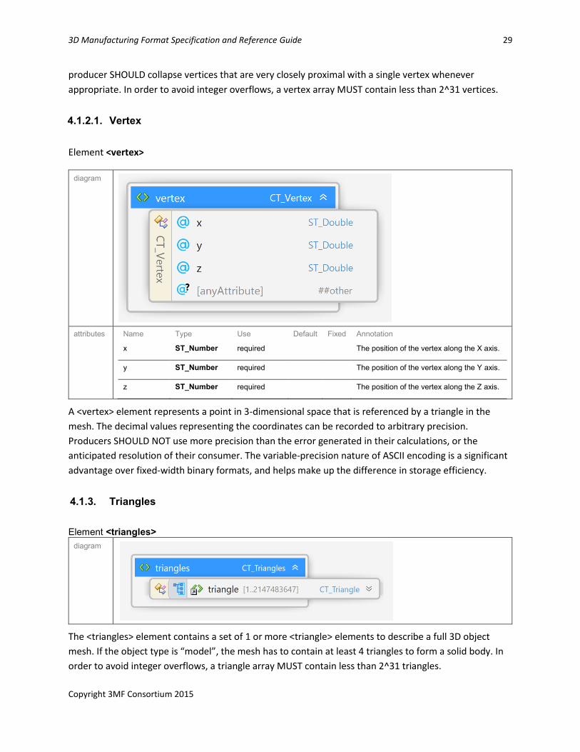
4.1.2.1. Vertex
Element <vertex>
diagram
attributes Name Type Use Default Fixed Annotation
x ST_Number required The position of the vertex along the X axis.
y ST_Number required The position of the vertex along the Y axis.
z ST_Number required The position of the vertex along the Z axis.
A <vertex> element represents a point in 3-dimensional space that is referenced by a triangle in the
mesh. The decimal values representing the coordinates can be recorded to arbitrary precision.
Producers SHOULD NOT use more precision than the error generated in their calculations, or the
anticipated resolution of their consumer. The variable-precision nature of ASCII encoding is a significant
advantage over fixed-width binary formats, and helps make up the difference in storage efficiency.
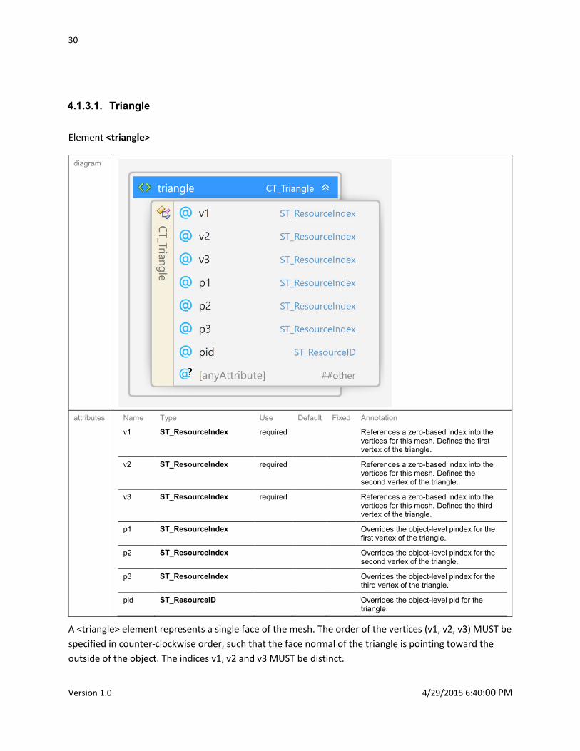
4.1.3. Triangles
Element <triangles> diagram
The <triangles> element contains a set of 1 or more <triangle> elements to describe a full 3D object
mesh. If the object type is “model”, the mesh has to contain at least 4 triangles to form a solid body. In
order to avoid integer overflows, a triangle array MUST contain less than 2^31 triangles.
30
Version 1.0 4/29/2015 6:40:00 PM
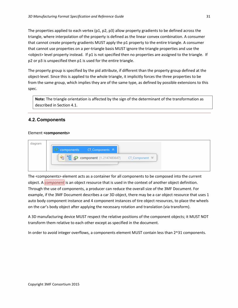
4.1.3.1. Triangle
Element <triangle>
diagram
attributes Name Type Use Default Fixed Annotation
v1 ST_ResourceIndex required References a zero-based index into the vertices for this mesh. Defines the first vertex of the triangle.
v2 ST_ResourceIndex required References a zero-based index into the vertices for this mesh. Defines the second vertex of the triangle.
v3 ST_ResourceIndex required References a zero-based index into the vertices for this mesh. Defines the third vertex of the triangle.
p1 ST_ResourceIndex Overrides the object-level pindex for the first vertex of the triangle.
p2 ST_ResourceIndex Overrides the object-level pindex for the second vertex of the triangle.
p3 ST_ResourceIndex Overrides the object-level pindex for the third vertex of the triangle.
pid ST_ResourceID Overrides the object-level pid for the triangle.
A <triangle> element represents a single face of the mesh. The order of the vertices (v1, v2, v3) MUST be
specified in counter-clockwise order, such that the face normal of the triangle is pointing toward the
outside of the object. The indices v1, v2 and v3 MUST be distinct.
3D Manufacturing Format Specification and Reference Guide 31
Copyright 3MF Consortium 2015
The properties applied to each vertex (p1, p2, p3) allow property gradients to be defined across the
triangle, where interpolation of the property is defined as the linear convex combination. A consumer
that cannot create property gradients MUST apply the p1 property to the entire triangle. A consumer
that cannot use properties on a per-triangle basis MUST ignore the triangle properties and use the
<object> level property instead. If p1 is not specified then no properties are assigned to the triangle. If
p2 or p3 is unspecified then p1 is used for the entire triangle.
The property group is specified by the pid attribute, if different than the property group defined at the
object-level. Since this is applied to the whole triangle, it implicitly forces the three properties to be
from the same group, which implies they are of the same type, as defined by possible extensions to this
spec.
Note: The triangle orientation is affected by the sign of the determinant of the transformation as
described in Section 4.1.
4.2. Components
Element <components>
diagram
The <components> element acts as a container for all components to be composed into the current
object. A component is an object resource that is used in the context of another object definition.
Through the use of components, a producer can reduce the overall size of the 3MF Document. For
example, if the 3MF Document describes a car 3D object, there may be a car object resource that uses 1
auto body component instance and 4 component instances of tire object resources, to place the wheels
on the car’s body object after applying the necessary rotation and translation (via transform).
A 3D manufacturing device MUST respect the relative positions of the component objects; it MUST NOT
transform them relative to each other except as specified in the document.
In order to avoid integer overflows, a components element MUST contain less than 2^31 components.
32
Version 1.0 4/29/2015 6:40:00 PM
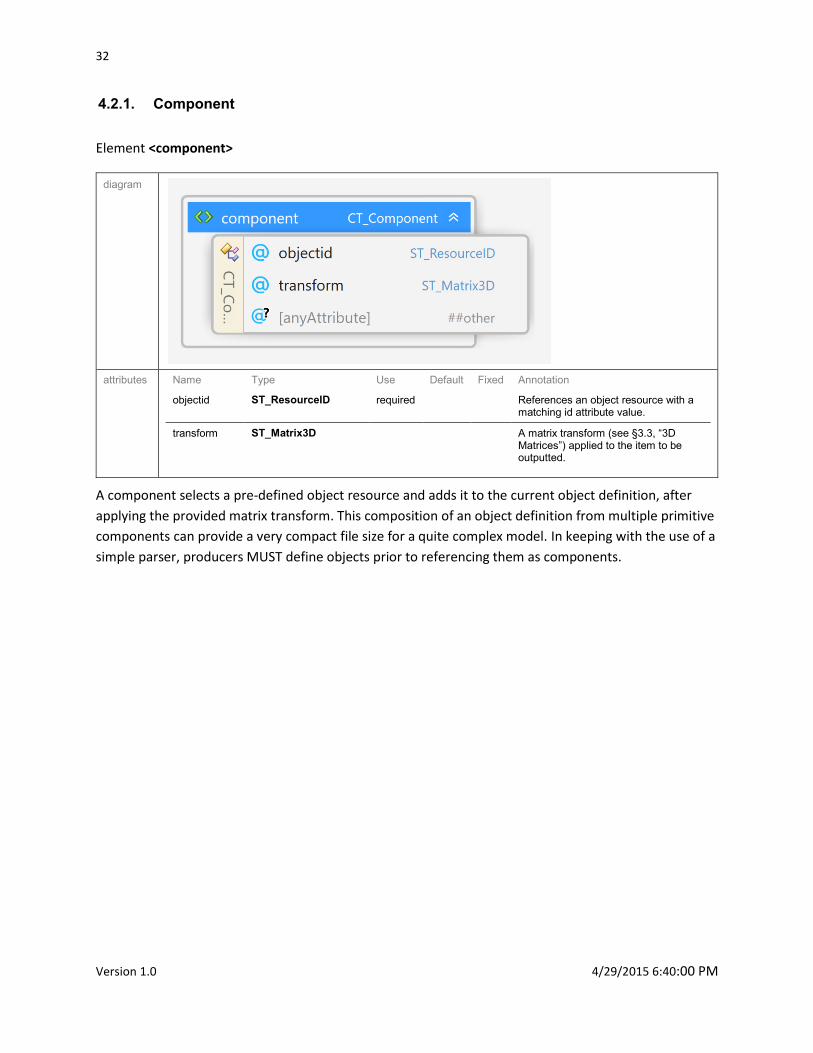
4.2.1. Component
Element <component>
diagram
attributes Name Type Use Default Fixed Annotation
objectid ST_ResourceID required References an object resource with a matching id attribute value.
transform ST_Matrix3D A matrix transform (see §3.3, “3D
Matrices”) applied to the item to be outputted.
A component selects a pre-defined object resource and adds it to the current object definition, after
applying the provided matrix transform. This composition of an object definition from multiple primitive
components can provide a very compact file size for a quite complex model. In keeping with the use of a
simple parser, producers MUST define objects prior to referencing them as components.
3D Manufacturing Format Specification and Reference Guide 33
Copyright 3MF Consortium 2015
Chapter 5. Material Resources
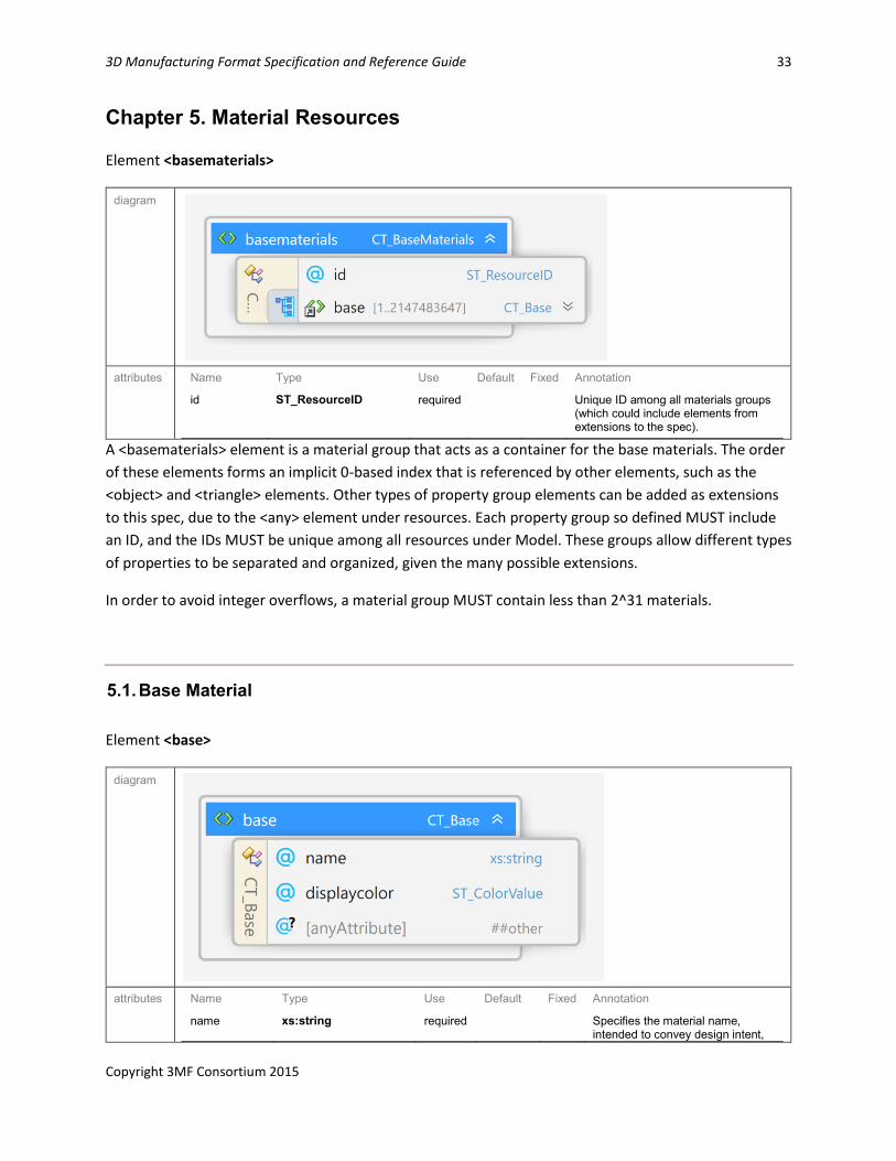
Element <basematerials>
diagram
attributes Name Type Use Default Fixed Annotation
id ST_ResourceID required Unique ID among all materials groups (which could include elements from extensions to the spec).
A <basematerials> element is a material group that acts as a container for the base materials. The order
of these elements forms an implicit 0-based index that is referenced by other elements, such as the
<object> and <triangle> elements. Other types of property group elements can be added as extensions
to this spec, due to the <any> element under resources. Each property group so defined MUST include
an ID, and the IDs MUST be unique among all resources under Model. These groups allow different types
of properties to be separated and organized, given the many possible extensions.
In order to avoid integer overflows, a material group MUST contain less than 2^31 materials.
5.1. Base Material
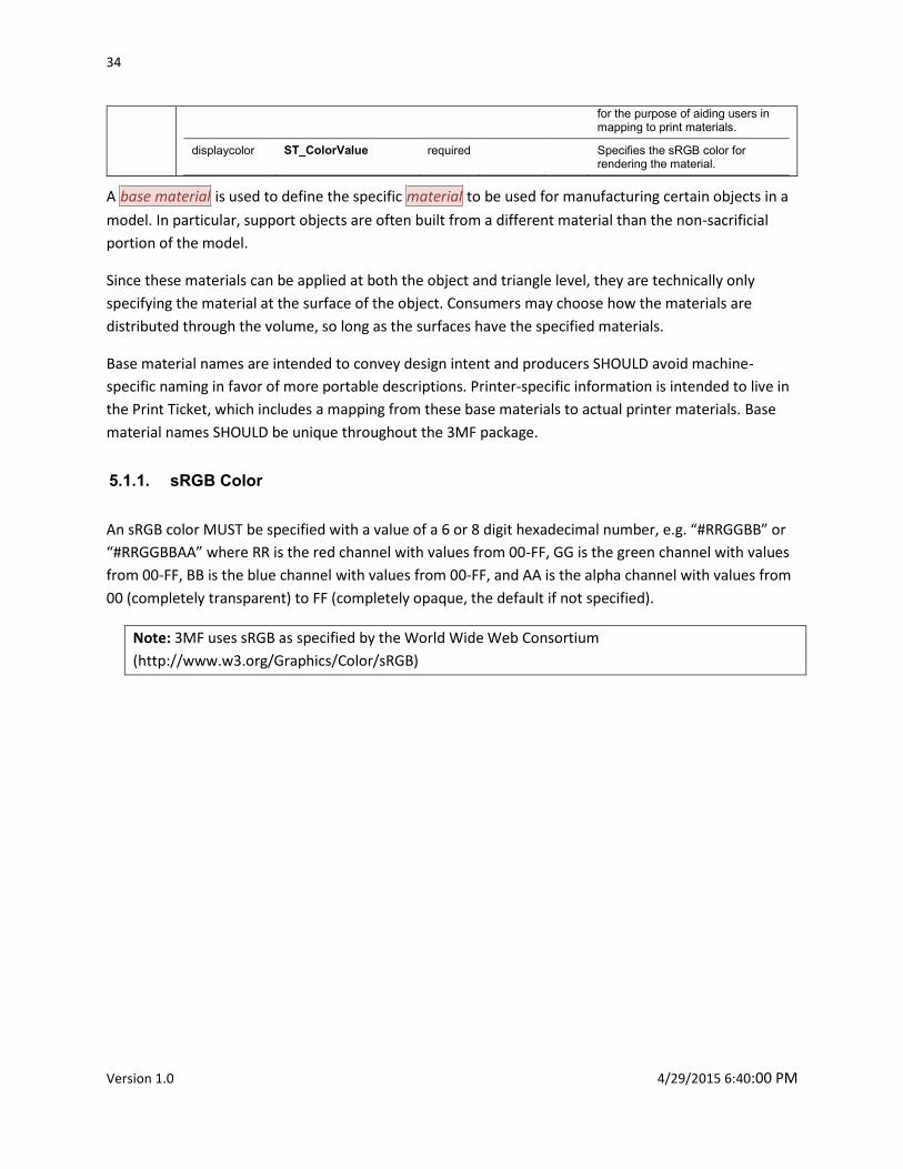
Element <base>
diagram
attributes Name Type Use Default Fixed Annotation
name xs:string required Specifies the material name, intended to convey design intent,
34
Version 1.0 4/29/2015 6:40:00 PM
for the purpose of aiding users in mapping to print materials.
displaycolor ST_ColorValue required Specifies the sRGB color for rendering the material.
A base material is used to define the specific material to be used for manufacturing certain objects in a
model. In particular, support objects are often built from a different material than the non-sacrificial
portion of the model.
Since these materials can be applied at both the object and triangle level, they are technically only
specifying the material at the surface of the object. Consumers may choose how the materials are
distributed through the volume, so long as the surfaces have the specified materials.
Base material names are intended to convey design intent and producers SHOULD avoid machine-
specific naming in favor of more portable descriptions. Printer-specific information is intended to live in
the Print Ticket, which includes a mapping from these base materials to actual printer materials. Base
material names SHOULD be unique throughout the 3MF package.
5.1.1. sRGB Color
An sRGB color MUST be specified with a value of a 6 or 8 digit hexadecimal number, e.g. “#RRGGBB” or
“#RRGGBBAA” where RR is the red channel with values from 00-FF, GG is the green channel with values
from 00-FF, BB is the blue channel with values from 00-FF, and AA is the alpha channel with values from
00 (completely transparent) to FF (completely opaque, the default if not specified).
Note: 3MF uses sRGB as specified by the World Wide Web Consortium
(http://www.w3.org/Graphics/Color/sRGB)
3D Manufacturing Format Specification and Reference Guide 35
Copyright 3MF Consortium 2015
Chapter 6. 3MF Document Package Features
3MF Documents take advantage of parts defined by the Open Packaging Conventions to provide
additional information about the content in the package.
6.1. Thumbnail
The producer of a 3MF document MAY include a 2D thumbnail image representing the contents of the
3D payload. This image may be of content type image/jpeg or image/png, following the internal file
format requirements described in the following subsections.
This thumbnail has a relationship from the package root to the thumbnail image. The relationship type
MUST be:
http://schemas.openxmlformats.org/package/2006/relationships/metadata/thumbnail
The thumbnail can be accessed and displayed by external systems, such as the operating system’s file
explorer, a model browser, or a print queue preview utility.
6.1.1. JPEG Images
JPEG image parts MUST contain images that conform to the JPEG specification. Consumers SHOULD
support JPEG images that contain APP0, APP2, APP13, and APP14 markers. Consumers MUST support
JPEG images that contain the APP1 marker and interpret the EXIF color space correctly.
Table 2–3. Supported JPEG APPn markers
APPn Marker Originating source
APP0 JFIF specification
APP1 EXIF extension defined by JEITA
APP2 ICC profile marker defined by the ICC specification
APP13 Photoshop 3.0 extension
APP14 Adobe DCT Filters in PostScript Level 2 extension
CMYK JPEG images MUST NOT be used.
Note: If both APP2 and APP13 markers are specified, the APP2 marker takes precedence.
6.1.2. PNG Images
PNG image parts MUST contain images that conform to the PNG specification.
36
Version 1.0 4/29/2015 6:40:00 PM
Table 2–4. Support for ancillary PNG chunks
Chunk Support Level
tRNS MUST Support
iCCP MUST Support
sRGB MUST Ignore
cHRM MUST Ignore
gAMA MUST Ignore
sBIT MUST Ignore
6.2. Core Properties
The 3MF Document format relies on the Core Properties part, defined in the Open Packaging
Conventions specification, to provide metadata about the creation time, modification time, author,
search keywords, and other document-centric metadata. See the Open Packaging Conventions
specification for additional details.
6.3. Digital Signatures
3MF Documents may contain one or more digital signatures. A digital signature provides a mechanism
to verify that a 3MF Document has not been tampered with since it was signed. The absence of a digital
signature cannot prove that a 3MF Document was never signed.
The Open Packaging Conventions specification provides full details of how digital signatures are applied
in OPC packages. The Digital Signature Origin part acts as the root of the digital signature payload in the
3MF Document. Individual Digital Signature parts can be discovered via relationship from the Digital
Signature Origin part. Each Digital Signature part can have either an inline digital certificate, or a
reference to an external Digital Signature Certificate part in the package.
A digital signature applied to the 3D Model part SHOULD include only the 3D Model part and any other
parts referenced by it, along with the associated relationships. It MAY include the Thumbnail, Digital
Signature Origin, Core Properties parts and associated relationship parts.
6.3.1. Normalization
Before applying or verifying a digital signature on the contents of the 3D Model part, the XML therein
MUST first be normalized, which is equivalent to XML canonicalization according to XML C14N
requirements.
3D Manufacturing Format Specification and Reference Guide 37
Copyright 3MF Consortium 2015
6.4. Protected Content
This specification does not include any content protection mechanism of its own. However, it is
recognized that for some workflows (e.g. those where a 3MF Document is stored as a stand-alone file),
it is important to prevent an intercepting party from accessing 3D object details as they travel from the
point of production or distribution through to the point of intended consumption on an authorized
device or by an authorized application or user.
The Open Packaging Conventions specification provides full details of how content is protected in OPC
packages.
A consumer that is authorized to un-protect content by reversing the above steps MUST NOT re-save
the content or enable the user to save the content in an unprotected fashion (regardless of file format)
without the approval (written or programmatic) of the protection authority (which might or might not
be the producer).
38
Version 1.0 4/29/2015 6:40:00 PM
PART II. APPENDIXES
3D Manufacturing Format Specification and Reference Guide 39
Copyright 3MF Consortium 2015
Appendix A. Glossary
3D matrix. A 4x4 affine matrix used for rotating, scaling, and translating an object in three-dimensional
space.
3D model. The markup that defines a model for output.
3D Model part. The OPC part that contains a 3D model.
3D Texture part. A file used to apply complex information to a 3D object in the 3D Model part
(undefined in this spec, but available for extensions).
3MF. The 3D Manufacturing Format described by this specification, defining one or more 3D objects
intended for output to a physical form.
3MF Document. The digital manifestation of an OPC package that contains a 3D payload that conforms
with the 3MF specification.
3MF Document StartPart relationship. The OPC relationship from the root of the package to the 3D
Model part.
Assembly. A model that contains two or more independently-defined objects that are connected or
interlocked either during or after the 3D manufacturing process is complete. An assembly might be able
to be reversed or the individual parts may be inseparably interlocked.
Back. The maximum printable XZ plane of the print area or the correspondent maximum plane of a
model bounding box, once transformed to the output coordinate space.
Bottom. The minimum printable XY plane of the print area or the correspondent minimum plane of a
model bounding box, once transformed to the output coordinate space.
Component. An object that is added as an intact shape to the overall definition of another object.
Consumer. A software, service, or device that reads in a 3MF Document.
Core properties. The well-defined set package (OPC) properties that define metadata about the package
as a whole, such as the author, the last modified time, and so on.
Digital signatures. A mechanism that, when present, can be used to validate that a part or payload has
not been tampered with or changed since the digital signature was applied.
Editor. A software, service, or device that both reads in and writes out 3MF Documents, possibly
changing the content in between.
Fill rule. The algorithm used to determine whether any particular point is considered to be “inside” the
geometry or not.
40
Version 1.0 4/29/2015 6:40:00 PM
Front. The minimum printable XZ plane of the print area or the correspondent minimum plane of a
model bounding box, once transformed to the output coordinate space.
Left. The minimum printable YZ plane of the print area or the correspondent minimum plane of a model
bounding box, once transformed to the output coordinate space.
Material. The description of a physical substance that can be used to output an object.
Material resource. A potential resource that might be referenced by an object to describe what the
object will be made of.
Mesh. A triangular tessellation of an object’s surface.
Metadata. Ancillary information about some portion of the model, to provide more refined processing
by knowledgeable producers or consumers.
Model. The set of objects that are to be manufactured as part of a single job. This may include a single
object, multiple instances of the same object, multiple different objects, or multiple objects in an
assembly.
Object resource. A single 3D shape that could be output by a 3D manufacturing device or used as a
component in another object resource.
Payload. A complete collection of interdependent parts and relationships within a package.
PrintTicket. The contents of a PrintTicket part. Conforms to the Print Schema Specification. It is
RECOMMENDED to use the standard Print Schema Keywords for 3D Manufacturing when possible.
PrintTicket part. The PrintTicket part provides settings used when the 3MF Document is printed.
Primary 3D payload root. The 3D payload discovered by the 3MF Document StartPart relationship.
Producer. A software, service, or device that writes out a 3MF Document.
Protection authority. The owner of the protection mechanism described by the protection type. This
may be the producer that originally protected the file, the consumer that defines what protection
mechanism will be accepted, or a third-party protection service, such as a digital rights management
service.
Protection namespace. The XML namespace that the protection type and associated metadata are
drawn from. It is declared on the <model > element.
Protection type. The qualified name for a protection mechanism that has been applied to the resources
and textures of the 3MF Document. This could be as simple as an XOR obfuscation or as complex as a
full digital rights management solution. The valid protection types are not defined in this specification
and are implementation dependent.

3D Manufacturing Format Specification and Reference Guide 41
Copyright 3MF Consortium 2015
Resource. An object, material, or something else defined in an extension that could be used by another
resource or might be necessary to build a physical 3D object according to build instructions.
Right. The maximum printable YZ plane of the print area or the correspondent maximum plane of a
model bounding box, once transformed to the output coordinate space.
Support. Many 3D printers require scaffolding for overhanging areas in the model to keep them from
collapsing or warping; this scaffolding is referred to as support.
Thumbnail. An image that helps end-users identify the contents of the package, expressed as a JPEG or
PNG image.
Thumbnail part. The OPC part that contains the package thumbnail image.
Top. The maximum printable XY plane of the print area or the correspondent maximum plane of a
model bounding box, once transformed to the output coordinate space.
XML namespace. A namespace declared on the <model> element, in accordance with the XML
Namespaces specification.
42
Version 1.0 4/29/2015 6:40:00 PM
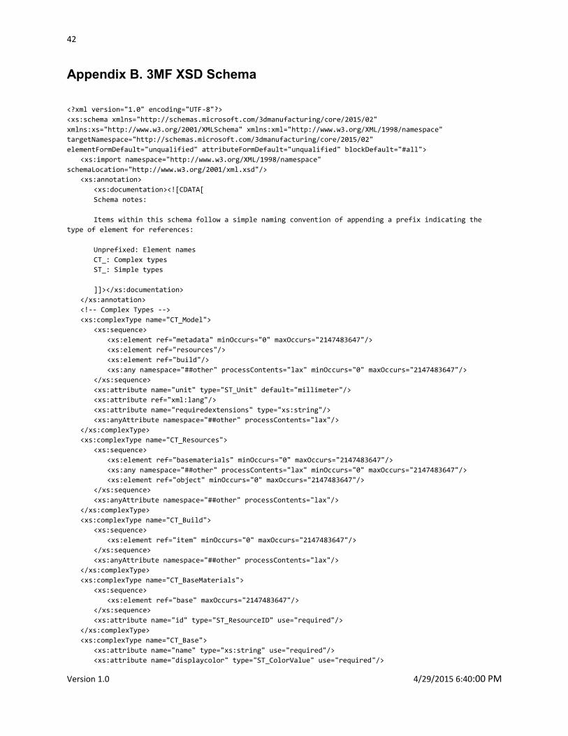
Appendix B. 3MF XSD Schema
<?xml version="1.0" encoding="UTF-8"?>
<xs:schema xmlns="http://schemas.microsoft.com/3dmanufacturing/core/2015/02"
xmlns:xs="http://www.w3.org/2001/XMLSchema" xmlns:xml="http://www.w3.org/XML/1998/namespace"
targetNamespace="http://schemas.microsoft.com/3dmanufacturing/core/2015/02"
elementFormDefault="unqualified" attributeFormDefault="unqualified" blockDefault="#all">
<xs:import namespace="http://www.w3.org/XML/1998/namespace"
schemaLocation="http://www.w3.org/2001/xml.xsd"/>
<xs:annotation>
<xs:documentation><![CDATA[
Schema notes:
Items within this schema follow a simple naming convention of appending a prefix indicating the
type of element for references:
Unprefixed: Element names
CT_: Complex types
ST_: Simple types
]]></xs:documentation>
</xs:annotation>
<!-- Complex Types -->
<xs:complexType name="CT_Model">
<xs:sequence>
<xs:element ref="metadata" minOccurs="0" maxOccurs="2147483647"/>
<xs:element ref="resources"/>
<xs:element ref="build"/>
<xs:any namespace="##other" processContents="lax" minOccurs="0" maxOccurs="2147483647"/>
</xs:sequence>
<xs:attribute name="unit" type="ST_Unit" default="millimeter"/>
<xs:attribute ref="xml:lang"/>
<xs:attribute name="requiredextensions" type="xs:string"/>
<xs:anyAttribute namespace="##other" processContents="lax"/>
</xs:complexType>
<xs:complexType name="CT_Resources">
<xs:sequence>
<xs:element ref="basematerials" minOccurs="0" maxOccurs="2147483647"/>
<xs:any namespace="##other" processContents="lax" minOccurs="0" maxOccurs="2147483647"/>
<xs:element ref="object" minOccurs="0" maxOccurs="2147483647"/>
</xs:sequence>
<xs:anyAttribute namespace="##other" processContents="lax"/>
</xs:complexType>
<xs:complexType name="CT_Build">
<xs:sequence>
<xs:element ref="item" minOccurs="0" maxOccurs="2147483647"/>
</xs:sequence>
<xs:anyAttribute namespace="##other" processContents="lax"/>
</xs:complexType>
<xs:complexType name="CT_BaseMaterials">
<xs:sequence>
<xs:element ref="base" maxOccurs="2147483647"/>
</xs:sequence>
<xs:attribute name="id" type="ST_ResourceID" use="required"/>
</xs:complexType>
<xs:complexType name="CT_Base">
<xs:attribute name="name" type="xs:string" use="required"/>
<xs:attribute name="displaycolor" type="ST_ColorValue" use="required"/>
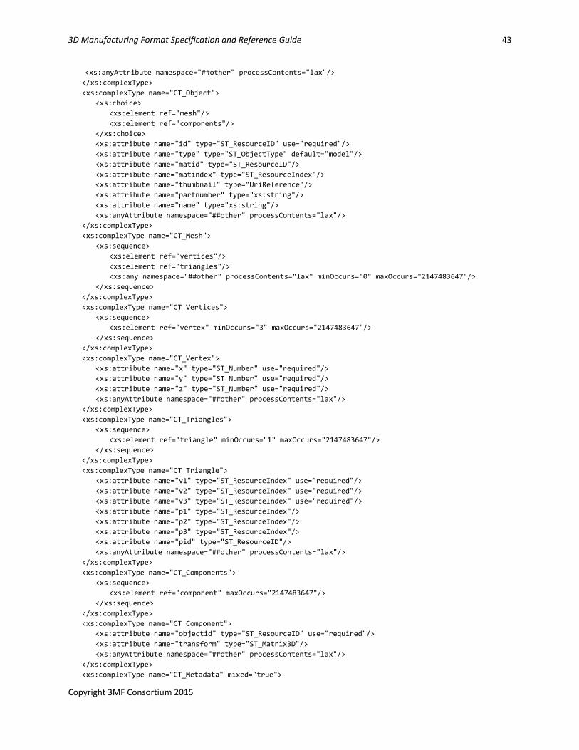
3D Manufacturing Format Specification and Reference Guide 43
Copyright 3MF Consortium 2015
<xs:anyAttribute namespace="##other" processContents="lax"/>
</xs:complexType>
<xs:complexType name="CT_Object">
<xs:choice>
<xs:element ref="mesh"/>
<xs:element ref="components"/>
</xs:choice>
<xs:attribute name="id" type="ST_ResourceID" use="required"/>
<xs:attribute name="type" type="ST_ObjectType" default="model"/>
<xs:attribute name="matid" type="ST_ResourceID"/>
<xs:attribute name="matindex" type="ST_ResourceIndex"/>
<xs:attribute name="thumbnail" type="UriReference"/>
<xs:attribute name="partnumber" type="xs:string"/>
<xs:attribute name="name" type="xs:string"/>
<xs:anyAttribute namespace="##other" processContents="lax"/>
</xs:complexType>
<xs:complexType name="CT_Mesh">
<xs:sequence>
<xs:element ref="vertices"/>
<xs:element ref="triangles"/>
<xs:any namespace="##other" processContents="lax" minOccurs="0" maxOccurs="2147483647"/>
</xs:sequence>
</xs:complexType>
<xs:complexType name="CT_Vertices">
<xs:sequence>
<xs:element ref="vertex" minOccurs="3" maxOccurs="2147483647"/>
</xs:sequence>
</xs:complexType>
<xs:complexType name="CT_Vertex">
<xs:attribute name="x" type="ST_Number" use="required"/>
<xs:attribute name="y" type="ST_Number" use="required"/>
<xs:attribute name="z" type="ST_Number" use="required"/>
<xs:anyAttribute namespace="##other" processContents="lax"/>
</xs:complexType>
<xs:complexType name="CT_Triangles">
<xs:sequence>
<xs:element ref="triangle" minOccurs="1" maxOccurs="2147483647"/>
</xs:sequence>
</xs:complexType>
<xs:complexType name="CT_Triangle">
<xs:attribute name="v1" type="ST_ResourceIndex" use="required"/>
<xs:attribute name="v2" type="ST_ResourceIndex" use="required"/>
<xs:attribute name="v3" type="ST_ResourceIndex" use="required"/>
<xs:attribute name="p1" type="ST_ResourceIndex"/>
<xs:attribute name="p2" type="ST_ResourceIndex"/>
<xs:attribute name="p3" type="ST_ResourceIndex"/>
<xs:attribute name="pid" type="ST_ResourceID"/>
<xs:anyAttribute namespace="##other" processContents="lax"/>
</xs:complexType>
<xs:complexType name="CT_Components">
<xs:sequence>
<xs:element ref="component" maxOccurs="2147483647"/>
</xs:sequence>
</xs:complexType>
<xs:complexType name="CT_Component">
<xs:attribute name="objectid" type="ST_ResourceID" use="required"/>
<xs:attribute name="transform" type="ST_Matrix3D"/>
<xs:anyAttribute namespace="##other" processContents="lax"/>
</xs:complexType>
<xs:complexType name="CT_Metadata" mixed="true">
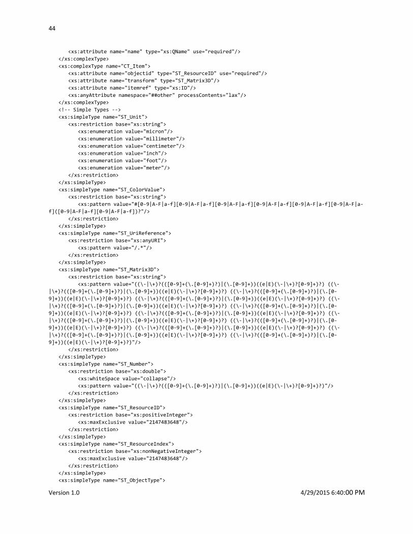
44
Version 1.0 4/29/2015 6:40:00 PM
<xs:attribute name="name" type="xs:QName" use="required"/>
</xs:complexType>
<xs:complexType name="CT_Item">
<xs:attribute name="objectid" type="ST_ResourceID" use="required"/>
<xs:attribute name="transform" type="ST_Matrix3D"/>
<xs:attribute name="itemref" type="xs:ID"/>
<xs:anyAttribute namespace="##other" processContents="lax"/>
</xs:complexType>
<!-- Simple Types -->
<xs:simpleType name="ST_Unit">
<xs:restriction base="xs:string">
<xs:enumeration value="micron"/>
<xs:enumeration value="millimeter"/>
<xs:enumeration value="centimeter"/>
<xs:enumeration value="inch"/>
<xs:enumeration value="foot"/>
<xs:enumeration value="meter"/>
</xs:restriction>
</xs:simpleType>
<xs:simpleType name="ST_ColorValue">
<xs:restriction base="xs:string">
<xs:pattern value="#[0-9|A-F|a-f][0-9|A-F|a-f][0-9|A-F|a-f][0-9|A-F|a-f][0-9|A-F|a-f][0-9|A-F|a-
f]([0-9|A-F|a-f][0-9|A-F|a-f])?"/>
</xs:restriction>
</xs:simpleType>
<xs:simpleType name="ST_UriReference">
<xs:restriction base="xs:anyURI">
<xs:pattern value="/.*"/>
</xs:restriction>
</xs:simpleType>
<xs:simpleType name="ST_Matrix3D">
<xs:restriction base="xs:string">
<xs:pattern value="((\-|\+)?(([0-9]+(\.[0-9]+)?)|(\.[0-9]+))((e|E)(\-|\+)?[0-9]+)?) ((\-
|\+)?(([0-9]+(\.[0-9]+)?)|(\.[0-9]+))((e|E)(\-|\+)?[0-9]+)?) ((\-|\+)?(([0-9]+(\.[0-9]+)?)|(\.[0-
9]+))((e|E)(\-|\+)?[0-9]+)?) ((\-|\+)?(([0-9]+(\.[0-9]+)?)|(\.[0-9]+))((e|E)(\-|\+)?[0-9]+)?) ((\-
|\+)?(([0-9]+(\.[0-9]+)?)|(\.[0-9]+))((e|E)(\-|\+)?[0-9]+)?) ((\-|\+)?(([0-9]+(\.[0-9]+)?)|(\.[0-
9]+))((e|E)(\-|\+)?[0-9]+)?) ((\-|\+)?(([0-9]+(\.[0-9]+)?)|(\.[0-9]+))((e|E)(\-|\+)?[0-9]+)?) ((\-
|\+)?(([0-9]+(\.[0-9]+)?)|(\.[0-9]+))((e|E)(\-|\+)?[0-9]+)?) ((\-|\+)?(([0-9]+(\.[0-9]+)?)|(\.[0-
9]+))((e|E)(\-|\+)?[0-9]+)?) ((\-|\+)?(([0-9]+(\.[0-9]+)?)|(\.[0-9]+))((e|E)(\-|\+)?[0-9]+)?) ((\-
|\+)?(([0-9]+(\.[0-9]+)?)|(\.[0-9]+))((e|E)(\-|\+)?[0-9]+)?) ((\-|\+)?(([0-9]+(\.[0-9]+)?)|(\.[0-
9]+))((e|E)(\-|\+)?[0-9]+)?)"/>
</xs:restriction>
</xs:simpleType>
<xs:simpleType name="ST_Number">
<xs:restriction base="xs:double">
<xs:whiteSpace value="collapse"/>
<xs:pattern value="((\-|\+)?(([0-9]+(\.[0-9]+)?)|(\.[0-9]+))((e|E)(\-|\+)?[0-9]+)?)"/>
</xs:restriction>
</xs:simpleType>
<xs:simpleType name="ST_ResourceID">
<xs:restriction base="xs:positiveInteger">
<xs:maxExclusive value="2147483648"/>
</xs:restriction>
</xs:simpleType>
<xs:simpleType name="ST_ResourceIndex">
<xs:restriction base="xs:nonNegativeInteger">
<xs:maxExclusive value="2147483648"/>
</xs:restriction>
</xs:simpleType>
<xs:simpleType name="ST_ObjectType">
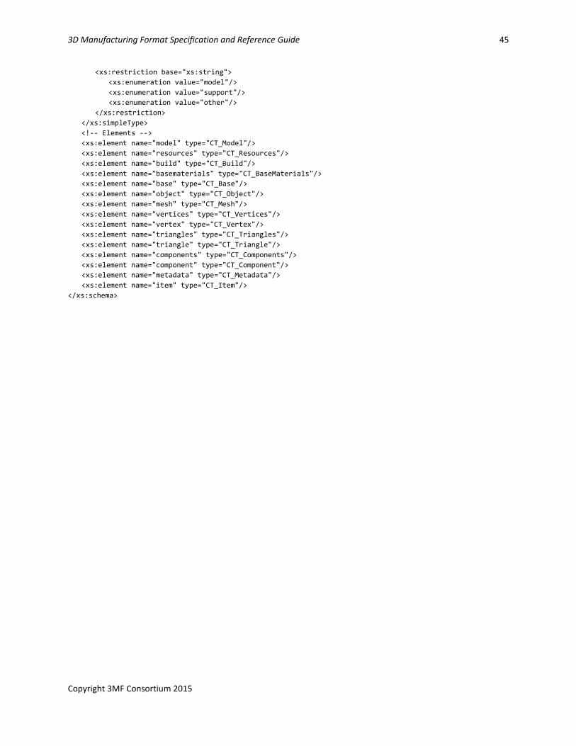
3D Manufacturing Format Specification and Reference Guide 45
Copyright 3MF Consortium 2015
<xs:restriction base="xs:string">
<xs:enumeration value="model"/>
<xs:enumeration value="support"/>
<xs:enumeration value="other"/>
</xs:restriction>
</xs:simpleType>
<!-- Elements -->
<xs:element name="model" type="CT_Model"/>
<xs:element name="resources" type="CT_Resources"/>
<xs:element name="build" type="CT_Build"/>
<xs:element name="basematerials" type="CT_BaseMaterials"/>
<xs:element name="base" type="CT_Base"/>
<xs:element name="object" type="CT_Object"/>
<xs:element name="mesh" type="CT_Mesh"/>
<xs:element name="vertices" type="CT_Vertices"/>
<xs:element name="vertex" type="CT_Vertex"/>
<xs:element name="triangles" type="CT_Triangles"/>
<xs:element name="triangle" type="CT_Triangle"/>
<xs:element name="components" type="CT_Components"/>
<xs:element name="component" type="CT_Component"/>
<xs:element name="metadata" type="CT_Metadata"/>
<xs:element name="item" type="CT_Item"/>
</xs:schema>
46
Version 1.0 4/29/2015 6:40:00 PM
Appendix C. Standard Namespaces and Content Types
C.1 Content Types
3D Model application/vnd.ms-package.3dmanufacturing-3dmodel+xml
PrintTicket application/vnd.ms-printing.printticket+xml
C.2 Relationship Types
StartPart http://schemas.microsoft.com/3dmanufacturing/2013/01/3dmodel
Thumbnail http://schemas.openxmlformats.org/package/2006/relationships/metadata/thumbnail
PrintTicket http://schemas.microsoft.com/3dmanufacturing/2013/01/printticket
C.3 Namespaces
3D Model http://schemas.microsoft.com/3dmanufacturing/core/2015/02
3D Manufacturing Format Specification and Reference Guide 47
Copyright 3MF Consortium 2015
References
BNF of Generic URI Syntax
“BNF of Generic URI Syntax.” World Wide Web Consortium.
http://www.w3.org/Addressing/URL/5_URI_BNF.html
JPEG
Hamilton, Eric. “JPEG File Interchange Format, Version 1.02.” World Wide Web Consortium. 1992.
http://www.w3.org/Graphics/JPEG/jfif3.pdf
Open Packaging Conventions
Ecma International. “Office Open XML Part 2: Open Packaging Conventions.” 2006. http://www.ecma-
international.org
PNG
Duce, David (editor). “Portable Network Graphics (PNG) Specification,” Second Edition. World Wide Web
Consortium. 2003. http://www.w3.org/TR/2003/REC-PNG-20031110
Print Schema
Microsoft Corporation. “Print Schema.” 2006. http://windowssdk.msdn.microsoft.com/en-
us/library/default.aspx
RFC 2119
Bradner, S. “Key words for use in RFCs to Indicate Requirement Levels.” The Internet Society. 1997.
http://www.rfc-editor.org
RFC 3066
Alvestrand, H. “Tags for the Identification of Languages.” The Internet Society. 2001. http://www.rfc-
editor.org
sRGB
Anderson, Matthew, Srinivasan Chandrasekar, Ricardo Motta, and Michael Stokes. “A Standard Default
Color Space for the Internet-sRGB, Version 1.10.” World Wide Web Consortium. 1996.
http://www.w3.org/Graphics/Color/sRGB
Unicode
The Unicode Consortium. The Unicode Standard, Version 4.0.0, defined by: The Unicode Standard,
Version 4.0. Boston, MA: Addison-Wesley, 2003.
48
Version 1.0 4/29/2015 6:40:00 PM
XML
Bray, Tim, Eve Maler, Jean Paoli, C. M. Sperlberg-McQueen, and François Yergeau (editors). “Extensible
Markup Language (XML) 1.0 (Fourth Edition).” World Wide Web Consortium. 2006.
http://www.w3.org/TR/2006/REC-xml-20060816/
XML C14N
Boyer, John. "Canonical XML Version 1.0." World Wide Web Consortium. 2001.
http://www.w3.org/TR/xml-c14n.
XML Namespaces
Bray, Tim, Dave Hollander, Andrew Layman, and Richard Tobin (editors). “Namespaces in XML 1.0
(Second Edition).” World Wide Web Consortium. 2006. http://www.w3.org/TR/2006/REC-xml-names-
20060816/
XML Schema
Beech, David, Murray Maloney, Noah Mendelsohn, and Henry S. Thompson (editors). “XML Schema Part
1: Structures,” Second Edition. World Wide Web Consortium. 2004. http://www.w3.org/TR/2004/REC-
xmlschema-1-20041028/
Biron, Paul V. and Ashok Malhotra (editors). “XML Schema Part 2: Datatypes,” Second Edition. World
Wide Web Consortium. 2004. http://www.w3.org/TR/2004/REC-xmlschema-2-20041028/