Embed Size (px)
Citation preview
CMM-2011 – Computer Methods in Mechanics 9–12 May 2011, Warsaw, Poland
3D buckling analysis of a cylindrical metal bin composed of horizontally corrugated sheets strengthened by vertical columns
Michal Wojcik and Jacek Tejchman
Gdańsk University of Technology, Faculty of Civil and Environmental Engineering
Narutowicza 11/12, 80-952 Gdańsk tel.: (0 58) 347 14 81, 347 14 81, fax: (0 58) 347 26 96
e-mail: [email protected], [email protected]
Abstract The paper presents 3D results of a quasi-static buckling analysis of a funnel-flow cylindrical metal bin composed of horizontally
corrugated sheets strengthened by vertical columns. A linear buckling and a non-linear analysis with geometric and material non-linearity were carried out with a perfect and an imperfect shell by taking into account axisymmetric and non-axisymmetric loads imposed by a bulk solid following Eurocode 1, different initial geometric imperfections and load non-uniformities around the circumference. The calculated buckling forces were compared with the permissible ones given by Eurocode 3. For a perfect bin the buckling strength was 3 times higher from a 3D analysis than this from Eurocode 3. If the wall amplitude of initial geometric imperfections was limited to about 10 cm, the calculated 3D buckling strength was similar as this given by Eurocode 3.
Keywords: buckling analysis, metal bin, geometric imperfections, loading imperfections, strength, corrugated walls
1. Introduction
Thin metal cylindrical shells are widely used as silos and tanks. They are vulnerable to buckling failures caused by the wall friction force due to the interaction between the silo fill and silo wall, particularly during eccentric discharge (which is usually difficult to avoid). As a consequence, non-uniform horizontal wall pressures develop leading to meridional bending. The buckling strength of shells depends on many different factors as: form and amplitude of initial geometric imperfections, loading and material imperfections, type of joints, boundary conditions at ends, level of internal pressurization and stiffness of the stored bulk solid. Metal silos can be built of thin-walled isotropic plain rolled sheets (which can be welded, riveted or screwed around the silo perimeter) or of thin-walled corrugated curved sheets strengthened by vertical stiffeners (columns) distributed uniformly around the silo circumference and connected with screws. Those latter are frequently used in the engineering practice due to an economical steel consumption and a small silo weight. In those silos, horizontally corrugated wall sheets carry horizontal tensile forces caused by horizontal wall pressure of a bulk solid and vertical columns carry vertical compressive forces exerted by wall friction stress from a bulk solid. Sufficient buckling strength of vertical columns is of a major importance for dimensioning because it is the most frequent failure mode in these structures. The Eurocode 3 [1] gives a simplified formula to calculate the buckling strength of vertical columns around the silo circumference, which is very conservative since it does not take into account a real 3D behaviour of a silo.
The aim of the present research is to perform a 3D buckling quasi-static analysis of a cylindrical metal bin with horizontally corrugated sheets and vertical columns and to compare the calculated buckling strength with that given by Eurocode 3 [1]. A linear buckling analysis and a non-linear FE analysis (with both geometric and material non-linearity) were carried out with a perfect and an imperfect silo shell by taking into account uniform and non-uniform loads exerted by a bulk solid (specified by Eurocode 1 [2]) and different initial wall geometric imperfections and additional load non-uniformities along the silo circumference.
2. Situation
The calculations were carried out with a single cylindrical metal silo. The height of a silo was H=21.48 m and its diameter D=5.35 m. The cross-section area was 22.48 m2 and the perimeter 16.81 m. The silo mantle consisted of 24 rings made from horizontally corrugated sheets 890×2940×0.75 mm3 based on a foundation slab. The silo was strengthened by 18 vertical columns composed of open thin-walled profiles with a varying cross-section uniformly placed along the silo circumference at a constant distance of 0.933 m. The columns were connected to the wall sheets by screws. The silo contained wheat and was concentrically filled and emptied. It was designed for funnel flow. The wall loads in a silo were calculated according to Eurocode 1 [2]. During axisymmetric emptying, the standard maximum wall normal and shear stress were in the bin ph=29 kPa and pw=13 kPa, respectively. The maximum characteristic horizontal tensile normal stress in corrugated sheets was equal to 110 MPa and was significantly smaller than the permissible steel normal stress equal to 280 MPa. The characteristic buckling strength of columns according to Eurocode 3 [1] was exceeded in one column profile by 15% for symmetric emptying and in 2 profiles by 50% for symmetric and non-symmetric emptying. The column buckled at the characteristic wall shear stress equal to pw=11.5 kPa (i.e. pw≅0.88×13 kPa for axisymmetric emptying or pw≅0.67×17 kPa for both axisymmetric and non-axisymmetric emptying).
3. 3D buckling FE analysis of silo shell
The 3D calculations were carried out with the cylindrical bin (curved corrugated walls and 18 vertical columns with a varying cross-section) using a commercial finite element package Abaqus [3]. The hopper and silo roof were omitted. The corrugated sheets were fixed to the columns at the sheet wave top at a constant distance of 0.076 m (thus, screw connections were not modeled). The 4-node thin shell elements with a reduced integration point were employed. The total amount of finite elements was 700’000. The minimum 5 shell elements were assumed to describe the curvature of corrugated
CMM-2011 – Computer Methods in Mechanics 9–12 May 2011, Warsaw, Poland
sheets. The element size was 7×130 mm2 (126 elements were taken along the silo circumference). For columns, the elements size was 10×36 mm2 (265 elements were taken along the silo height). The bin columns were fixed at the bottom. The 2 types of analyses were considered for the reference silo: LBA – a linear buckling (eigenvalue) analysis of the elastic stiffness matrix and GMNA – a geometrically and materially non-linear analysis of the perfect and imperfect silo (by tracing a force-deflection path). The steel was assumed to be elastic (linear buckling analysis) or elastic-perfectly plastic (non-linear analysis) with the following properties: modulus of elasticity E=210 GPa, Poisson’s ratio v=0.3 and yield stress fy=350 MPa. In a non-linear analysis, the automatic Riks method [3] was used to determine a load-deflection or buckling load factor-deflection diagram. In the calculations, the loads caused by both the axisymmetric wall shear stress and wall horizontal normal stress (beneficial to the buckling strength) and a local non-axisymmetric horizontal wall normal stress (so-called “patch load” for thin-walled silos detrimental to the buckling strength) were taken into account [2]. In the last case, the horizontal wall load in the shape of a cosine curve around the entire bin circumference accounting for the effect of pressure non-uniformity was assumed.
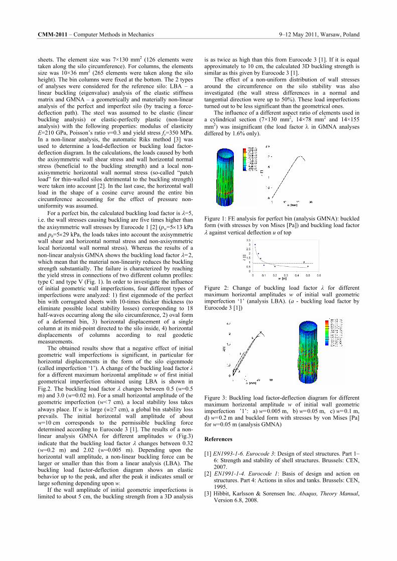
For a perfect bin, the calculated buckling load factor is λ=5, i.e. the wall stresses causing buckling are five times higher than the axisymmetric wall stresses by Eurocode 1 [2] (pw=5×13 kPa and ph=5×29 kPa, the loads takes into account the axisymmetric wall shear and horizontal normal stress and non-axisymmetric local horizontal wall normal stress). Whereas the results of a non-linear analysis GMNA shows the buckling load factor λ=2, which mean that the material non-linearity reduces the buckling strength substantially. The failure is characterized by reaching the yield stress in connections of two different column profiles: type C and type V (Fig. 1). In order to investigate the influence of initial geometric wall imperfections, four different types of imperfections were analyzed: 1) first eigenmode of the perfect bin with corrugated sheets with 10-times thicker thickness (to eliminate possible local stability losses) corresponding to 18 half-waves occurring along the silo circumference, 2) oval form of a deformed bin, 3) horizontal displacement of a single column at its mid-point directed to the silo inside, 4) horizontal displacements of columns according to real geodetic measurements.
The obtained results show that a negative effect of initial geometric wall imperfections is significant, in particular for horizontal displacements in the form of the silo eigenmode (called imperfection ‘1’). A change of the buckling load factor λ for a different maximum horizontal amplitude w of first initial geometrical imperfection obtained using LBA is shown in Fig.2. The buckling load factor λ changes between 0.5 (w=0.5 m) and 3.0 (w=0.02 m). For a small horizontal amplitude of the geometric imperfection (w<7 cm), a local stability loss takes always place. If w is large (w≥7 cm), a global bin stability loss prevails. The initial horizontal wall amplitude of about w=10 cm corresponds to the permissible buckling force determined according to Eurocode 3 [1]. The results of a non-linear analysis GMNA for different amplitudes w (Fig.3) indicate that the buckling load factor λ changes between 0.32 (w=0.2 m) and 2.02 (w=0.005 m). Depending upon the horizontal wall amplitude, a non-linear buckling force can be larger or smaller than this from a linear analysis (LBA). The buckling load factor-deflection diagram shows an elastic behavior up to the peak, and after the peak it indicates small or large softening depending upon w.
If the wall amplitude of initial geometric imperfections is limited to about 5 cm, the buckling strength from a 3D analysis
is as twice as high than this from Eurocode 3 [1]. If it is equal approximately to 10 cm, the calculated 3D buckling strength is similar as this given by Eurocode 3 [1].
The effect of a non-uniform distribution of wall stresses around the circumference on the silo stability was also investigated (the wall stress differences in a normal and tangential direction were up to 50%). These load imperfections turned out to be less significant than the geometrical ones.
The influence of a different aspect ratio of elements used in a cylindrical section (7×130 mm2, 14×78 mm2 and 14×155 mm2) was insignificant (the load factor λ in GMNA analyses differed by 1.6% only).
Figure 1: FE analysis for perfect bin (analysis GMNA): buckled form (with stresses by von Mises [Pa]) and buckling load factor λ against vertical deflection u of top
Figure 2: Change of buckling load factor λ for different maximum horizontal amplitudes w of initial wall geometric imperfection ‘1’ (analysis LBA). (a - buckling load factor by Eurocode 3 [1])
Figure 3: Buckling load factor-deflection diagram for different maximum horizontal amplitude w of initial wall geometric imperfection ’1’: a) w=0.005 m, b) w=0.05 m, c) w=0.1 m, d) w=0.2 m and buckled form with stresses by von Mises [Pa] for w=0.05 m (analysis GMNA)
References
[1] EN1993-1-6. Eurocode 3: Design of steel structures. Part 1–6: Strength and stability of shell structures. Brussels: CEN, 2007.
[2] EN1991-1-4. Eurocode 1: Basis of design and action on structures. Part 4: Actions in silos and tanks. Brussels: CEN, 1995.
[3] Hibbit, Karlsson & Sorensen Inc. Abaqus, Theory Manual, Version 6.8, 2008.


![Thermomechanical Buckling of Simply Supported …jmee.isme.ir/article_20567_59428197b92e994c077f0008f1169483.pdfShahsiah and Eslami [3] analyzed the thermal buckling of FGM cylindrical](https://img.pdfslide.us/doc/110x75/5ab81ae47f8b9ad13d8c2d05/thermomechanical-buckling-of-simply-supported-jmeeismeirarticle2056759428197b92e.jpg)