Embed Size (px)
Citation preview
Instructions - Parts
ProProPro Xp™Xp™Xp™ 606060 WBWBWB GunGunGun3A7504A
EN
AnAnAn electrostaticelectrostaticelectrostatic airairair spraysprayspray gungungun forforfor sprayingsprayingspraying conductive,conductive,conductive, waterbornewaterbornewaterborne fluidsfluidsfluids thatthatthat meetmeetmeet atatat leastleastleast oneoneone ofofof thethetheconditionsconditionsconditions forforfor nonnonnon---flammabilityflammabilityflammability listedlistedlisted ononon pagepagepage 3.3.3.ForForFor professionalprofessionalprofessional useuseuse only.only.only.
ImportantImportantImportant SafetySafetySafety InstructionsInstructionsInstructionsRead all warnings and instructions in this manual and in the isolationsystem manual before using the equipment. SaveSaveSave thesethesethese instructions.instructions.instructions.
100 psi (0.7 MPa, 7.0 bar) MaximumFluid Working Pressure100 psi (0.7 MPa, 7.0 bar) Maximum AirWorking PressureSee page 3 for model part numbers andapproval information.
PROVEN QUALITY. LEADING TECHNOLOGY.
ContentsContentsContents
Models............................................................... 3Related Manuals ................................................ 3Warnings ........................................................... 4Gun Overview .................................................... 7
How the Electrostatic Spray GunWorks ............................................ 7
Spraying Waterborne FluidsElectrostatically .............................. 7
Controls, Indicators, and Components ........... 8Smart Guns ................................................. 9
Installation.......................................................... 14System Requirements .................................. 14Warning Sign............................................... 14Install the System......................................... 14Ventilate the Spray Booth ............................. 14Typical Installation ....................................... 15Connect the Waterborne Fluid Hose.............. 16Air Supply Line ............................................ 17Grounding ................................................... 18
Gun Setup.......................................................... 20Gun Setup Procedure................................... 20Soft Spray Gun Setup Procedure .................. 24HVLP Gun Setup Procedure ......................... 25Round Spray Gun Setup Procedure .............. 26Abrasive Material Gun Setup
Procedure ...................................... 28Mold Release Gun Setup Procedure ............. 30Check Gun Electrical Grounding ................... 32Flush Before Using Equipment...................... 32
Operation........................................................... 33Pressure Relief Procedure............................ 33Fluid Voltage Discharge and Grounding
Procedure ...................................... 33Startup ........................................................ 34Shutdown .................................................... 34
Maintenance ...................................................... 35Daily Care and Cleaning Checklist ................ 35Flushing ...................................................... 35Clean the Gun Daily ..................................... 36Daily System Care ....................................... 38
Electrical Tests ................................................... 39Test Gun Resistance.................................... 39Test Power Supply Resistance ..................... 39Test Electrode Resistance ............................ 40
Troubleshooting.................................................. 41Voltage Loss Troubleshooting....................... 41Spray Pattern Troubleshooting...................... 44Gun Operation Troubleshooting .................... 45Electrical Troubleshooting ............................ 46
Repair................................................................ 48Prepare the Gun for Service ......................... 48Air Cap and Nozzle Replacement.................. 49Air Cap, Spray Tip, and Nozzle
Replacement (ModelL60M19) ........................................ 50
Electrode Replacement ................................ 52Needle Replacement (Model L60M19) ........... 52Fluid Packing Rod Removal.......................... 53Packing Rod Repair ..................................... 53Barrel Removal ............................................ 55Barrel Installation ......................................... 55Power Supply Removal and
Replacement .................................. 56Alternator Removal and Replacement ........... 57Fan Air Adjustment Valve Repair .................. 59Atomizing Air Restrictor Valve Repair ............ 60ES On-Off and Fluid Adjustment Valve
Repair............................................ 61Air Valve Repair........................................... 62Smart Module Replacement.......................... 62Air Swivel and Exhaust Valve
Replacement .................................. 63Parts.................................................................. 64
Standard Waterborne Air Spray GunAssembly ....................................... 64
Smart Waterborne Air Spray GunAssembly ....................................... 66
Mold Release Smart Air Spray GunAssembly ....................................... 68
Packing Rod Assembly................................. 70Alternator Assembly ..................................... 71ES On-Off and Fluid Adjustment Valve ........... 72Fan Air Adjustment Valve Assembly.............. 73Atomizing Air Restrictor Valve
Assembly ....................................... 73Air Cap Assembly ........................................ 74Smart Module Assembly............................... 74Round Spray Assembly ................................ 75
Fluid Nozzles ..................................................... 77Fluid Nozzle Selection Chart......................... 77Fluid Nozzle Performance Charts.................. 78
Air Caps............................................................. 80Air Cap Selection Guide ............................... 80Air Consumption Charts ............................... 85
Spray Tip Selection Chart (Model L60M19 MRGGun Only) ............................................. 86
AEM Fine Finish Spray Tips.......................... 86AEF Fine Finish Pre-Orifice Spray
Tips ............................................... 87Round Spray Tips ........................................ 87
Repair Kits and Accessories................................ 88Fluid Hose Assembly and Repair .................. 91
Ignitability of Coating Materials ............................ 92Dimensions ........................................................ 93Technical Specifications...................................... 94California Proposition 65 ..................................... 94Notes ................................................................ 95Graco Pro Xp Warranty....................................... 96
2 3A7504A
Models
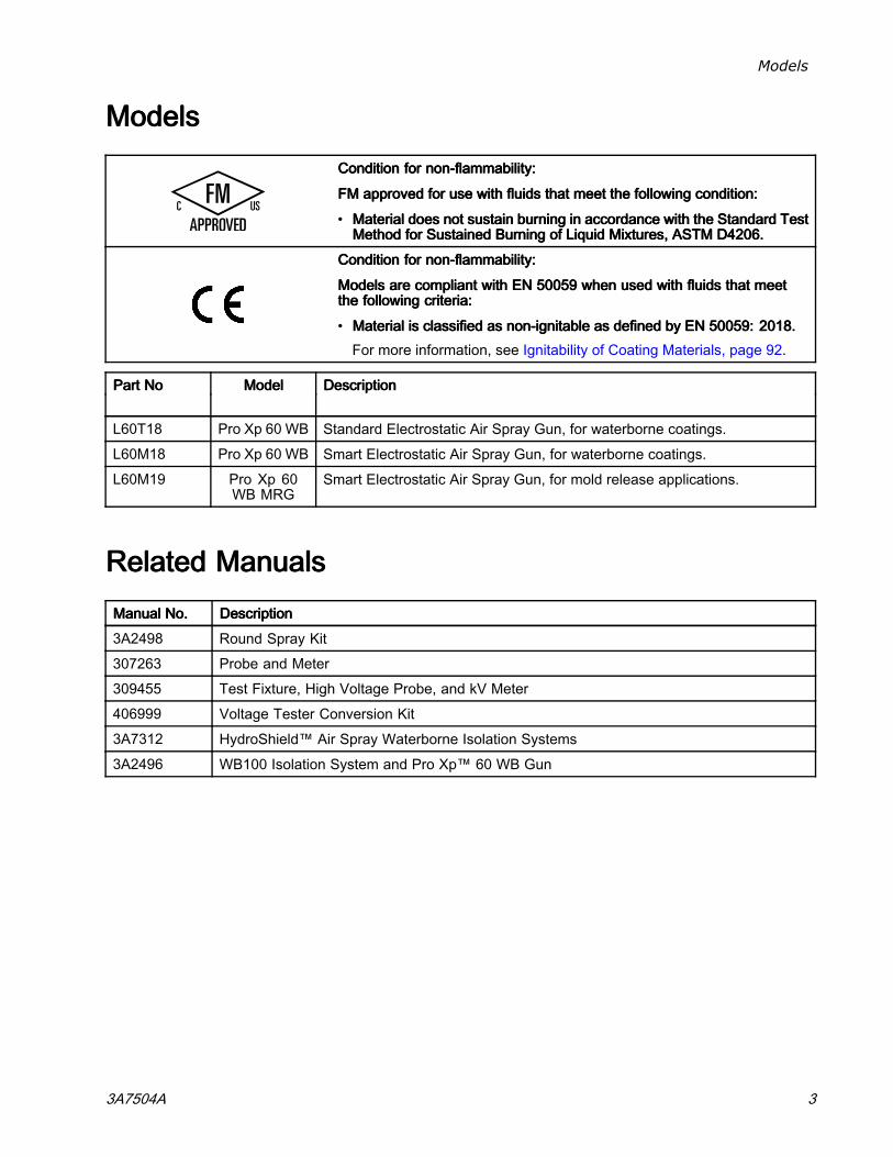
ModelsModelsModelsConditionConditionCondition forforfor nonnonnon---flammability:flammability:flammability:
FMFMFM approvedapprovedapproved forforfor useuseuse withwithwith fluidsfluidsfluids thatthatthat meetmeetmeet thethethe followingfollowingfollowing condition:condition:condition:
• MaterialMaterialMaterial doesdoesdoes notnotnot sustainsustainsustain burningburningburning ininin accordanceaccordanceaccordance withwithwith thethethe StandardStandardStandard TestTestTestMethodMethodMethod forforfor SustainedSustainedSustained BurningBurningBurning ofofof LiquidLiquidLiquid Mixtures,Mixtures,Mixtures, ASTMASTMASTM D4206.D4206.D4206.
ConditionConditionCondition forforfor nonnonnon---flammability:flammability:flammability:
ModelsModelsModels areareare compliantcompliantcompliant withwithwith ENENEN 500595005950059 whenwhenwhen usedusedused withwithwith fluidsfluidsfluids thatthatthat meetmeetmeetthethethe followingfollowingfollowing criteria:criteria:criteria:
• MaterialMaterialMaterial isisis classifiedclassifiedclassified asasas nonnonnon---ignitableignitableignitable asasas defineddefineddefined bybyby ENENEN 50059:50059:50059: 2018.2018.2018.For more information, see Ignitability of Coating Materials, page 92.
PartPartPart NoNoNo ModelModelModel DescriptionDescriptionDescription
L60T18 Pro Xp 60 WB Standard Electrostatic Air Spray Gun, for waterborne coatings.
L60M18 Pro Xp 60 WB Smart Electrostatic Air Spray Gun, for waterborne coatings.
L60M19 Pro Xp 60WB MRG
Smart Electrostatic Air Spray Gun, for mold release applications.
RelatedRelatedRelated ManualsManualsManualsManualManualManual No.No.No. DescriptionDescriptionDescription
3A2498 Round Spray Kit
307263 Probe and Meter
309455 Test Fixture, High Voltage Probe, and kV Meter
406999 Voltage Tester Conversion Kit
3A7312 HydroShield™ Air Spray Waterborne Isolation Systems
3A2496 WB100 Isolation System and Pro Xp™ 60 WB Gun
3A7504A 3
Warnings
WarningsWarningsWarnings
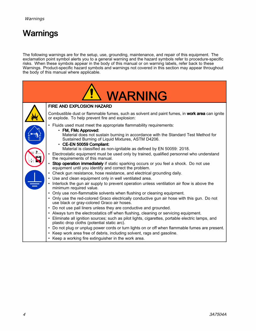
The following warnings are for the setup, use, grounding, maintenance, and repair of this equipment. Theexclamation point symbol alerts you to a general warning and the hazard symbols refer to procedure-specificrisks. When these symbols appear in the body of this manual or on warning labels, refer back to theseWarnings. Product-specific hazard symbols and warnings not covered in this section may appear throughoutthe body of this manual where applicable.
WARNINGWARNINGWARNINGFIREFIREFIRE ANDANDAND EXPLOSIONEXPLOSIONEXPLOSION HAZARDHAZARDHAZARD
Combustible dust or flammable fumes, such as solvent and paint fumes, in workworkwork areaareaarea can igniteor explode. To help prevent fire and explosion:
• Fluids used must meet the appropriate flammability requirements:• FM,FM,FM, FMcFMcFMc Approved:Approved:Approved:Material does not sustain burning in accordance with the Standard Test Method forSustained Burning of Liquid Mixtures, ASTM D4206.
• CECECE---ENENEN 500595005950059 Compliant:Compliant:Compliant:Material is classified as non-ignitable as defined by EN 50059: 2018.
• Electrostatic equipment must be used only by trained, qualified personnel who understandthe requirements of this manual.
• StopStopStop operationoperationoperation immediatelyimmediatelyimmediately if static sparking occurs or you feel a shock. Do not useequipment until you identify and correct the problem.
• Check gun resistance, hose resistance, and electrical grounding daily.• Use and clean equipment only in well ventilated area.• Interlock the gun air supply to prevent operation unless ventilation air flow is above theminimum required value.
• Only use non-flammable solvents when flushing or cleaning equipment.• Only use the red-colored Graco electrically conductive gun air hose with this gun. Do notuse black or gray-colored Graco air hoses.
• Do not use pail liners unless they are conductive and grounded.• Always turn the electrostatics off when flushing, cleaning or servicing equipment.• Eliminate all ignition sources; such as pilot lights, cigarettes, portable electric lamps, andplastic drop cloths (potential static arc).
• Do not plug or unplug power cords or turn lights on or off when flammable fumes are present.• Keep work area free of debris, including solvent, rags and gasoline.• Keep a working fire extinguisher in the work area.
4 3A7504A
Warnings
WARNINGWARNINGWARNINGELECTRICELECTRICELECTRIC SHOCKSHOCKSHOCK HAZARDHAZARDHAZARD
This equipment must be grounded. Improper grounding, setup, or usage of the system cancause electric shock:
• Ground all equipment, personnel, object being sprayed, and conductive objects in or closeto spray area. See GroundingGroundingGrounding instructions.
• Connect the electrostatic gun to a voltage isolation system that will discharge the systemvoltage when not in use.
• All components of the isolation system that are charged to high voltage must be containedwithin an isolation enclosure that prevents personnel from making contact with the highvoltage components before the system voltage is discharged.
• Follow the FluidFluidFluid VoltageVoltageVoltage DischargeDischargeDischarge andandand GroundingGroundingGrounding ProcedureProcedureProcedure when instructed to dischargethe voltage; before cleaning, flushing, or servicing the system; before approaching the front ofthe gun; and before opening the isolation enclosure for the isolated fluid supply.
• Do not enter a high voltage or hazardous area until all high voltage equipment has beendischarged.
• Do not touch the gun nozzle or electrode, or come within 4 in. (102 mm) of the electrodeduring gun operation. Follow the FluidFluidFluid VoltageVoltageVoltage DischargeDischargeDischarge andandand GroundingGroundingGrounding ProcedureProcedureProcedure.
• Interlock the gun air supply with the voltage isolation system to shut off the air supply anytimethe isolation system enclosure is opened.
• Only use the red-colored Graco electrically conductive gun air hose with this gun. Do notuse black or gray-colored Graco air hoses.
• Do not splice hoses together. Install only one continuous Graco waterborne fluid hosebetween the isolated fluid supply and the spray gun.
PRESSURIZEDPRESSURIZEDPRESSURIZED EQUIPMENTEQUIPMENTEQUIPMENT HAZARDHAZARDHAZARDFluid from the equipment, leaks, or ruptured components can splash in the eyes or on skinand cause serious injury.
• Follow the PressurePressurePressure ReliefReliefRelief ProcedureProcedureProcedure when you stop spraying/dispensing and beforecleaning, checking, or servicing equipment.
• Tighten all fluid connections before operating the equipment.• Check hoses, tubes, and couplings daily. Replace worn or damaged parts immediately.
3A7504A 5
Warnings
WARNINGWARNINGWARNINGEQUIPMENTEQUIPMENTEQUIPMENT MISUSEMISUSEMISUSE HAZARDHAZARDHAZARDMisuse can cause death or serious injury.
• Do not operate the unit when fatigued or under the influence of drugs or alcohol.• Do not exceed the maximum working pressure or temperature rating of the lowest ratedsystem component. See TechnicalTechnicalTechnical SpecificationsSpecificationsSpecifications in all equipment manuals.
• Use fluids and solvents that are compatible with equipment wetted parts.. See TechnicalTechnicalTechnicalSpecificationsSpecificationsSpecifications in all equipment manuals. Read fluid and solvent manufacturer’s warnings.For complete information about your material, request a Safety Data Sheet (SDS) fromyour distributor or retailer.
• Do not leave the work area while equipment is energized or under pressure.• Turn off all equipment and follow the PressurePressurePressure ReliefReliefRelief ProcedureProcedureProcedure when equipment is not in use.• Check equipment daily. Repair or replace worn or damaged parts immediately with genuinemanufacturer’s replacement parts only.
• Do not alter or modify equipment. Alterations or modifications may void agency approvalsand create safety hazards.
• Make sure all equipment is rated and approved for the environment in which you are using it.• Use equipment only for its intended purpose. Call your distributor for information.• Route hoses and cables away from traffic areas, sharp edges, moving parts, and hot surfaces.• Do not kink or over bend hoses or use hoses to pull equipment.• Keep children and animals away from work area.• Comply with all applicable safety regulations.
PLASTICPLASTICPLASTIC PARTSPARTSPARTS CLEANINGCLEANINGCLEANING SOLVENTSOLVENTSOLVENT HAZARDHAZARDHAZARDMany solvents can degrade plastic parts and cause them to fail, which could cause seriousinjury or property damage.
• Use only compatible water-based solvents to clean plastic structural or pressure-containingparts.
• See TechnicalTechnicalTechnical SpecificationsSpecificationsSpecifications in all equipment manuals for materials of construction. Consultthe solvent manufacturer for information and recommendations about compatibility.
TOXICTOXICTOXIC FLUIDFLUIDFLUID OROROR FUMESFUMESFUMESToxic fluids or fumes can cause serious injury or death if splashed in the eyes or on skin,inhaled, or swallowed.
• Read Safety Data Sheet (SDS) to know the specific hazards of the fluids you are using.• Store hazardous fluid in approved containers, and dispose of it according to applicableguidelines.
PERSONALPERSONALPERSONAL PROTECTIVEPROTECTIVEPROTECTIVE EQUIPMENTEQUIPMENTEQUIPMENTWear appropriate protective equipment when in the work area to help prevent serious injury,including eye injury, hearing loss, inhalation of toxic fumes, and burns. This protectiveequipment includes but is not limited to:
• Protective eyewear, and hearing protection.• Respirators, protective clothing, and gloves as recommended by the fluid and solventmanufacturer.
6 3A7504A
Gun Overview
GunGunGun OverviewOverviewOverview
HowHowHow thethethe ElectrostaticElectrostaticElectrostatic SpraySpraySpray GunGunGunWorksWorksWorks
The air hose supplies air to the spray gun. Part of theair operates the alternator turbine and the rest of theair atomizes the fluid being sprayed.
The alternator generates power, which is convertedby the power cartridge to supply high voltage to thegun’s electrode.
The pump supplies fluid to the fluid hose and gun,where the fluid is electrostatically charged as itpasses the electrode. The charged fluid is attractedto the grounded workpiece, wrapping around andevenly coating all surfaces.
SprayingSprayingSpraying WaterborneWaterborneWaterborne FluidsFluidsFluidsElectrostaticallyElectrostaticallyElectrostatically
This electrostatic air spray gun is designed tospray onlyonlyonly waterborne fluids which meet one of thefollowing flammability requirements:
• FM,FM,FM, FMcFMcFMc Approved:Approved:Approved:Material does not sustain burning in accordancewith the Standard Test Method for SustainedBurning of Liquid Mixtures, ASTM D4206.
• CE-ENCE-ENCE-EN 500595005950059 Compliant:Compliant:Compliant:Material is classified as non-ignitable as defined byEN 50059: 2018.For more information, seeIgnitability of Coating Materials, page 92.
When connected to a voltage isolation system,all of the fluid in the spray gun, fluid hose, andisolated fluid supply is charged to high voltage,which means that the system has more electricalenergy than a solvent-based system. Therefore,only non-flammable fluids (as defined underModels, page 3 ) can be sprayed with the gun or beused to clean, flush, or purge the gun.
Precautions must be taken when using electrostaticwaterborne equipment to avoid potential shockhazards. When the spray gun charges the isolatedfluid to high voltage, it is similar to charging acapacitor or a battery.
The system will store some of the energy whilespraying and retain some of that energy after thespray gun is shut off. Because it takes some timefor that stored energy to discharge, it is importantto read the instructions, including the Fluid VoltageDischarge and Grounding Procedure, page 33, andGrounding, page 18, to understand when you canapproach or touch the gun nozzle.
The amount of time it takes to discharge theenergy depends on the system design. Follow theFluid Voltage Discharge and Grounding Procedure,page 33, before approaching the front of the gun.
3A7504A 7

Gun Overview
Controls,Controls,Controls, Indicators,Indicators,Indicators, andandand ComponentsComponentsComponents
The electrostatic gun includes the following controls, indicators, and components. For information on Smartguns, also see Smart Guns, page 9 .
Figure 1 Gun Overview
ItemItemItem DescriptionDescriptionDescription PurposePurposePurpose
A Air Swivel Inlet 1/4 npsm(m) left-hand thread, for Graco red-colored grounded airsupply hose.
B Fluid Inlet Graco waterborne fluid supply hose
C Turbine Air Exhaust Barbed fitting, for supplied exhaust tube.
D Air Cap and Nozzle For available sizes, see Air Caps, page 80 andFluid Nozzles, page 77.
E Electrode Needle Supplies electrostatic charge to the fluid.
F Fan Air Adjustment Valve Adjusts fan size and shape. Can be used to decrease pattern width.
G Atomizing Air RestrictorValve
Restricts air cap air flow. Replace with plug (included) if desired.
H Fluid Adjustment Knob Adjusts fluid flow by limiting fluid needle travel. Use only in low flowconditions, to reduce wear.
J ES On-Off Valve Turns electrostatics ON (I) or OFF (O).
K ES Indicator (standardgun only; for Smartgun indicator, seeOperating Mode, page 9 )
Lit when ES is ON (I). Color indicates alternator frequency. See theLED indicator table in Gun Setup Procedure, page 20.
8 3A7504A
Gun Overview
SmartSmartSmart GunsGunsGuns
The Smart Gun module displays spraying voltage,current, alternator speed, and the voltage setting (lowor high). It also allows the user to change to a lowerspraying voltage. The module has two modes:
• Operating Mode• Diagnostic Mode
OperatingOperatingOperating ModeModeMode
BarBarBar GraphGraphGraph
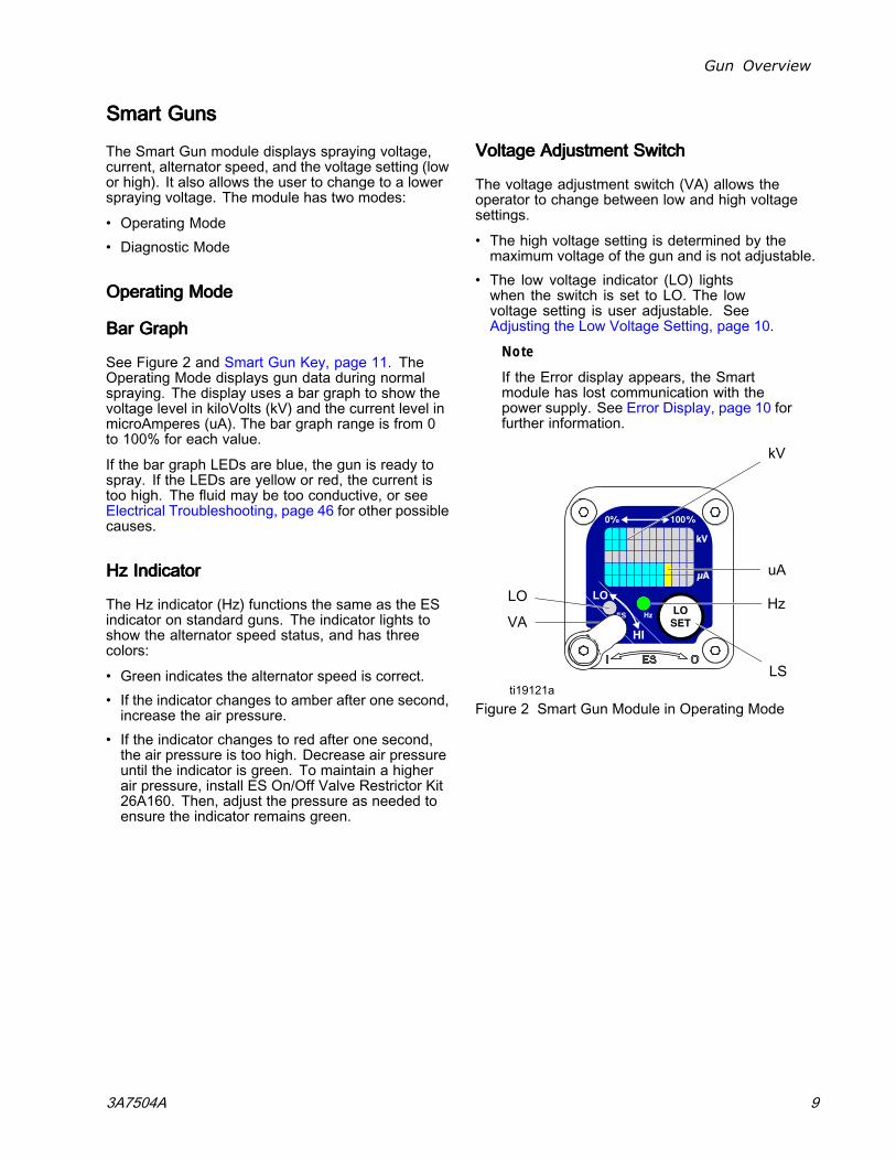
See Figure 2 and Smart Gun Key, page 11. TheOperating Mode displays gun data during normalspraying. The display uses a bar graph to show thevoltage level in kiloVolts (kV) and the current level inmicroAmperes (uA). The bar graph range is from 0to 100% for each value.
If the bar graph LEDs are blue, the gun is ready tospray. If the LEDs are yellow or red, the current istoo high. The fluid may be too conductive, or seeElectrical Troubleshooting, page 46 for other possiblecauses.
HzHzHz IndicatorIndicatorIndicator
The Hz indicator (Hz) functions the same as the ESindicator on standard guns. The indicator lights toshow the alternator speed status, and has threecolors:
• Green indicates the alternator speed is correct.• If the indicator changes to amber after one second,increase the air pressure.
• If the indicator changes to red after one second,the air pressure is too high. Decrease air pressureuntil the indicator is green. To maintain a higherair pressure, install ES On/Off Valve Restrictor Kit26A160. Then, adjust the pressure as needed toensure the indicator remains green.
VoltageVoltageVoltage AdjustmentAdjustmentAdjustment SwitchSwitchSwitch
The voltage adjustment switch (VA) allows theoperator to change between low and high voltagesettings.
• The high voltage setting is determined by themaximum voltage of the gun and is not adjustable.
• The low voltage indicator (LO) lightswhen the switch is set to LO. The lowvoltage setting is user adjustable. SeeAdjusting the Low Voltage Setting, page 10.
Note
If the Error display appears, the Smartmodule has lost communication with thepower supply. See Error Display, page 10 forfurther information.
Figure 2 Smart Gun Module in Operating Mode
3A7504A 9
Gun Overview
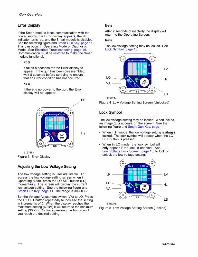
ErrorErrorError DisplayDisplayDisplay
If the Smart module loses communication with thepower supply, the Error display appears, the Hzindicator turns red, and the Smart module is disabled.See the following figure and Smart Gun Key, page 11.This can occur in Operating Mode or DiagnosticMode. See Electrical Troubleshooting, page 46.Communication must be restored to make the Smartmodule functional.
Note
It takes 8 seconds for the Error display toappear. If the gun has been disassembled,wait 8 seconds before spraying to ensurethat an Error condition has not occurred.
Note
If there is no power to the gun, the Errordisplay will not appear.
Figure 3 Error Display
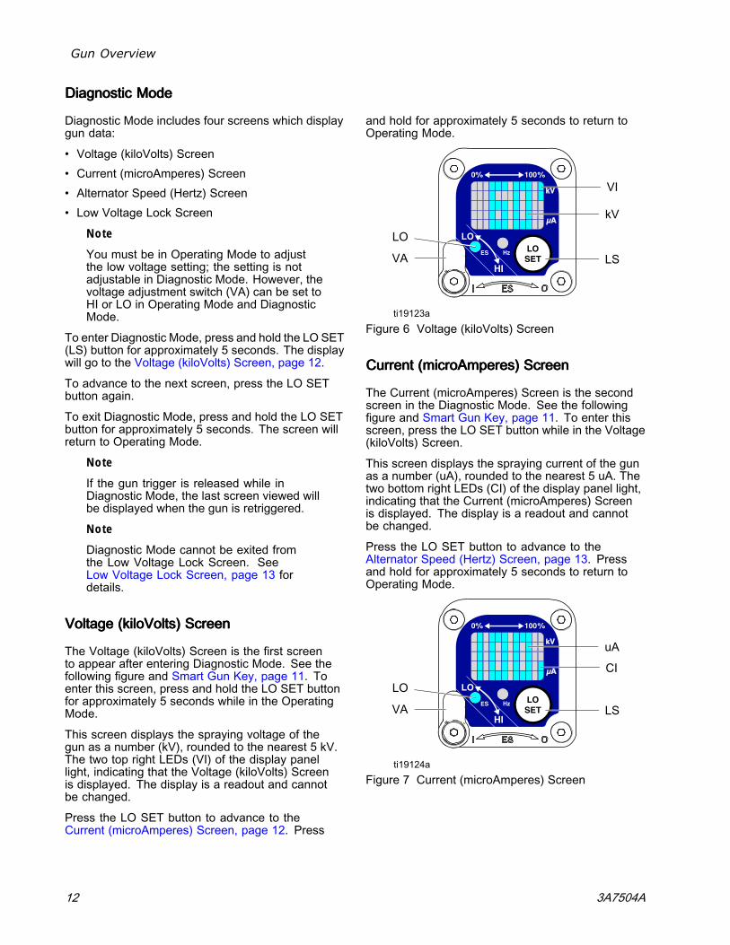
AdjustingAdjustingAdjusting thethethe LowLowLow VoltageVoltageVoltage SettingSettingSetting
The low voltage setting is user adjustable. Toaccess the low voltage setting screen when inOperating Mode, press the LO SET button (LS)momentarily. The screen will display the currentlow voltage setting. See the following figure andSmart Gun Key, page 11. The range is 30–60 kV.
Set the Voltage Adjustment switch (VA) to LO. Pressthe LO SET button repeatedly to increase the settingin increments of 5. When the display reaches themaximum setting (60 kV) it will return to the minimumsetting (30 kV). Continue pressing the button untilyou reach the desired setting.
Note
After 2 seconds of inactivity the display willreturn to the Operating Screen.
Note
The low voltage setting may be locked. SeeLock Symbol, page 10.
Figure 4 Low Voltage Setting Screen (Unlocked)
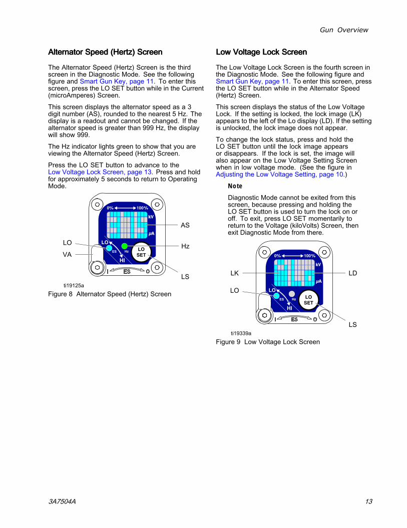
LockLockLock SymbolSymbolSymbol
The low voltage setting may be locked. When locked,an image (LK) appears on the screen. See thefollowing figure and Smart Gun Key, page 11.
• When in HI mode, the low voltage setting is alwaysalwaysalwayslocked. The lock symbol will appear when the LOSET button is pressed.
• When in LO mode, the lock symbol willonlyonlyonly appear if the lock is enabled. SeeLow Voltage Lock Screen, page 13, to lock orunlock the low voltage setting.
Figure 5 Low Voltage Setting Screen (Locked)
10 3A7504A

Gun Overview
SmartSmartSmart GunGunGun KeyKeyKey
TableTableTable 111 KeyKeyKey forforfor FiguresFiguresFigures 2–92–92–9
ItemItemItem DescriptionDescriptionDescription PurposePurposePurpose
VA Voltage Adjustment Switch Two-position switch sets Smart gun voltage to low setting (LO) orhigh setting (HI). This switch is functional in Operating Mode and inDiagnostic Mode.
LO Low Voltage ModeIndicator
Lights (blue) when the Smart gun is set to Low Voltage.
kV Voltage (kV) Display Displays actual spraying voltage of the gun, in kV. In Operating Mode,display is a bar graph. In Diagnostic Mode, voltage is displayed asa number.
uA Current (uA) Display Displays actual spraying current of the gun, in uA. In Operating Mode,display is a bar graph. In Diagnostic Mode, current is displayed asa number.
LS LO SET button Press momentarily to enter the Low Voltage Setting screen.
Press and hold for approximately 5 seconds to enter or exit DiagnosticMode.
While in Diagnostic Mode, press momentarily to advance throughscreens.
While on the Low Voltage Lock Screen (in Diagnostic Mode), pressand hold to turn the lock on or off.
LV Low Voltage Display Displays the low voltage setting as a number. The setting can bechanged. See Figure 4.
LK Low Voltage Locked Appears if the low voltage setting is locked. See Figure 5 and Figure 9.
LD LO Display Appears on the Low Voltage Lock Screen. See Figure 9.
ER Error Display Appears if the Smart module loses communication with the powersupply. See Figure 3.
VI Voltage Indicator In Diagnostic Mode, the two top right LEDs of the screen light,indicating that the value displayed is in kV. See Figure 6.
CI Current Indicator In Diagnostic Mode, the two bottom right LEDs of the screen light,indicating that the value displayed is in uA. See Figure 7.
AS Alternator Speed Display In Diagnostic Mode, Hz level is displayed as a number. See Figure 8.
Hz Alternator Speed Indicator In Operating Mode, indicator color varies to show the alternator speedstatus:
• Green indicates the alternator speed is at the correct level.• If the indicator changes to amber after one second, the alternatorspeed is too low.
• If the indicator changes to red after one second, the alternator speedis too high. The indicator also turns red if the Error display appears.
In Diagnostic Mode, the indicator is green when in the AlternatorSpeed (Hertz) screen.
3A7504A 11
Gun Overview
DiagnosticDiagnosticDiagnostic ModeModeMode
Diagnostic Mode includes four screens which displaygun data:
• Voltage (kiloVolts) Screen• Current (microAmperes) Screen• Alternator Speed (Hertz) Screen• Low Voltage Lock Screen
Note
You must be in Operating Mode to adjustthe low voltage setting; the setting is notadjustable in Diagnostic Mode. However, thevoltage adjustment switch (VA) can be set toHI or LO in Operating Mode and DiagnosticMode.
To enter Diagnostic Mode, press and hold the LO SET(LS) button for approximately 5 seconds. The displaywill go to the Voltage (kiloVolts) Screen, page 12.
To advance to the next screen, press the LO SETbutton again.
To exit Diagnostic Mode, press and hold the LO SETbutton for approximately 5 seconds. The screen willreturn to Operating Mode.
Note
If the gun trigger is released while inDiagnostic Mode, the last screen viewed willbe displayed when the gun is retriggered.
Note
Diagnostic Mode cannot be exited fromthe Low Voltage Lock Screen. SeeLow Voltage Lock Screen, page 13 fordetails.
VoltageVoltageVoltage (kiloVolts)(kiloVolts)(kiloVolts) ScreenScreenScreen
The Voltage (kiloVolts) Screen is the first screento appear after entering Diagnostic Mode. See thefollowing figure and Smart Gun Key, page 11. Toenter this screen, press and hold the LO SET buttonfor approximately 5 seconds while in the OperatingMode.
This screen displays the spraying voltage of thegun as a number (kV), rounded to the nearest 5 kV.The two top right LEDs (VI) of the display panellight, indicating that the Voltage (kiloVolts) Screenis displayed. The display is a readout and cannotbe changed.
Press the LO SET button to advance to theCurrent (microAmperes) Screen, page 12. Press
and hold for approximately 5 seconds to return toOperating Mode.
Figure 6 Voltage (kiloVolts) Screen
CurrentCurrentCurrent (microAmperes)(microAmperes)(microAmperes) ScreenScreenScreen
The Current (microAmperes) Screen is the secondscreen in the Diagnostic Mode. See the followingfigure and Smart Gun Key, page 11. To enter thisscreen, press the LO SET button while in the Voltage(kiloVolts) Screen.
This screen displays the spraying current of the gunas a number (uA), rounded to the nearest 5 uA. Thetwo bottom right LEDs (CI) of the display panel light,indicating that the Current (microAmperes) Screenis displayed. The display is a readout and cannotbe changed.
Press the LO SET button to advance to theAlternator Speed (Hertz) Screen, page 13. Pressand hold for approximately 5 seconds to return toOperating Mode.
Figure 7 Current (microAmperes) Screen
12 3A7504A
Gun Overview
AlternatorAlternatorAlternator SpeedSpeedSpeed (Hertz)(Hertz)(Hertz) ScreenScreenScreen
The Alternator Speed (Hertz) Screen is the thirdscreen in the Diagnostic Mode. See the followingfigure and Smart Gun Key, page 11. To enter thisscreen, press the LO SET button while in the Current(microAmperes) Screen.
This screen displays the alternator speed as a 3digit number (AS), rounded to the nearest 5 Hz. Thedisplay is a readout and cannot be changed. If thealternator speed is greater than 999 Hz, the displaywill show 999.
The Hz indicator lights green to show that you areviewing the Alternator Speed (Hertz) Screen.
Press the LO SET button to advance to theLow Voltage Lock Screen, page 13. Press and holdfor approximately 5 seconds to return to OperatingMode.
Figure 8 Alternator Speed (Hertz) Screen
LowLowLow VoltageVoltageVoltage LockLockLock ScreenScreenScreen
The Low Voltage Lock Screen is the fourth screen inthe Diagnostic Mode. See the following figure andSmart Gun Key, page 11. To enter this screen, pressthe LO SET button while in the Alternator Speed(Hertz) Screen.
This screen displays the status of the Low VoltageLock. If the setting is locked, the lock image (LK)appears to the left of the Lo display (LD). If the settingis unlocked, the lock image does not appear.
To change the lock status, press and hold theLO SET button until the lock image appearsor disappears. If the lock is set, the image willalso appear on the Low Voltage Setting Screenwhen in low voltage mode. (See the figure inAdjusting the Low Voltage Setting, page 10.)
Note
Diagnostic Mode cannot be exited from thisscreen, because pressing and holding theLO SET button is used to turn the lock on oroff. To exit, press LO SET momentarily toreturn to the Voltage (kiloVolts) Screen, thenexit Diagnostic Mode from there.
Figure 9 Low Voltage Lock Screen
3A7504A 13

Installation
InstallationInstallationInstallation
SystemSystemSystem RequirementsRequirementsRequirements
The use of multiple guns with one isolation cabinetmay cause electric shock, fire, or explosion. Tohelp prevent injury or equipment damage, use onlyone gun per isolation cabinet.
To spray with electrostatics, the spray gun must beconnected to a voltage isolation system such as aGraco HydroShield or WB100.
A voltage isolation system must have the followingfeatures:
• An isolation enclosure that prevents persons frommaking contact with the high voltage componentsbefore the system voltage is discharged. Allcomponents of the isolation system that arecharged to high voltage must be contained withinthe enclosure.
• A bleed resistor to drain off the system voltagewhen the spray gun is not in use. A metal part ofthe fluid supply unit must be electrically connectedto the bleed resistor.
• A safety interlock that automatically discharges thesystem voltage when anyone opens the isolationenclosure.
Note
The Graco warranty and approvals are void ifthe electrostatic spray gun is connected to anon-Graco voltage isolation system or if thegun is operated above 60 kV.
WarningWarningWarning SignSignSign
Mount warning signs in the spray area where theycan easily be seen and read by all operators. AnEnglish Warning Sign is provided with the gun.
InstallInstallInstall thethethe SystemSystemSystem
Installing and servicing this equipment requiresaccess to parts which may cause electric shockor other serious injury if work is not performedproperly.
• Do not install or service this equipment unlessyou are trained and qualified.
• Comply with all local codes and regulations
Typical Installation, page 15 shows a typicalelectrostatic air spray system. It is not an actualsystem design. For assistance in designing a systemto suit your particular needs, contact your Gracodistributor.
Set up and install the isolation system according tothe instructions for your isolation system.
VentilateVentilateVentilate thethethe SpraySpraySpray BoothBoothBooth
Do not operate the gun unless ventilating air flow isabove the minimum required value. Provide freshair ventilation to avoid the buildup of flammable ortoxic vapors when spraying, flushing, or cleaningthe gun. Interlock the gun air and fluid supplyto prevent operation unless ventilating air flow isabove the minimum required value.
The spray booth must have a ventilation system.
Electrically interlock the gun air and fluid supply withthe ventilators to prevent gun operation any time thatthe ventilation air flow falls below minimum values.Check and follow all local codes and regulationsregarding air exhaust velocity requirements. Verifythe operation of the interlock at least once a year.
14 3A7504A
Installation
TypicalTypicalTypical InstallationInstallationInstallation
Figure 10 Typical Installation of a Waterborne Gun
KeyKeyKey
ItemItemItem DescriptionDescriptionDescription
S Waterborne Electrostatic Air Spray Gun
AM Main Air Supply Line
AB* Bleed-Type Air Shutoff Valve
HG* Graco Red Grounded Air Hose (left-handthreads)
CA* Isolated System
PR Gun Air Pressure Regulator
ItemItemItem DescriptionDescriptionDescription
AS Gun Air Line Filter
GND* Gun Air Hose Ground Wire
SR Strain Relief Fitting
FJ* Graco Waterborne Fluid Hose
* These items are required for safe operation.
3A7504A 15
Installation
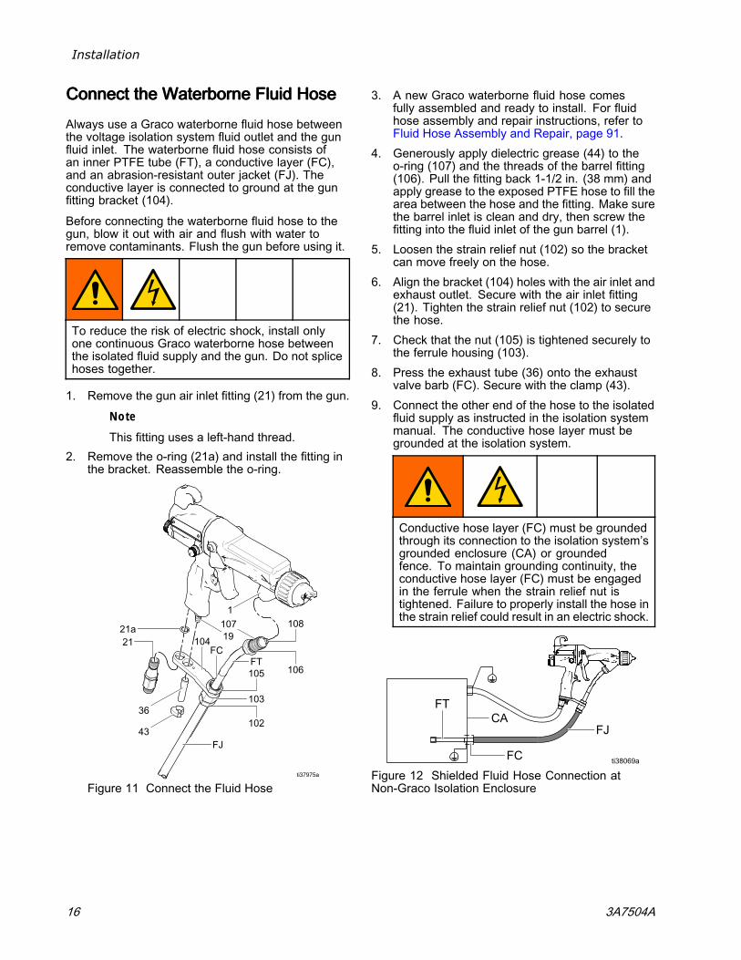
ConnectConnectConnect thethethe WaterborneWaterborneWaterborne FluidFluidFluid HoseHoseHose
Always use a Graco waterborne fluid hose betweenthe voltage isolation system fluid outlet and the gunfluid inlet. The waterborne fluid hose consists ofan inner PTFE tube (FT), a conductive layer (FC),and an abrasion-resistant outer jacket (FJ). Theconductive layer is connected to ground at the gunfitting bracket (104).
Before connecting the waterborne fluid hose to thegun, blow it out with air and flush with water toremove contaminants. Flush the gun before using it.
To reduce the risk of electric shock, install onlyone continuous Graco waterborne hose betweenthe isolated fluid supply and the gun. Do not splicehoses together.
1. Remove the gun air inlet fitting (21) from the gun.
NoteThis fitting uses a left-hand thread.
2. Remove the o-ring (21a) and install the fitting inthe bracket. Reassemble the o-ring.
Figure 11 Connect the Fluid Hose
3. A new Graco waterborne fluid hose comesfully assembled and ready to install. For fluidhose assembly and repair instructions, refer toFluid Hose Assembly and Repair, page 91.
4. Generously apply dielectric grease (44) to theo-ring (107) and the threads of the barrel fitting(106). Pull the fitting back 1-1/2 in. (38 mm) andapply grease to the exposed PTFE hose to fill thearea between the hose and the fitting. Make surethe barrel inlet is clean and dry, then screw thefitting into the fluid inlet of the gun barrel (1).
5. Loosen the strain relief nut (102) so the bracketcan move freely on the hose.
6. Align the bracket (104) holes with the air inlet andexhaust outlet. Secure with the air inlet fitting(21). Tighten the strain relief nut (102) to securethe hose.
7. Check that the nut (105) is tightened securely tothe ferrule housing (103).
8. Press the exhaust tube (36) onto the exhaustvalve barb (FC). Secure with the clamp (43).
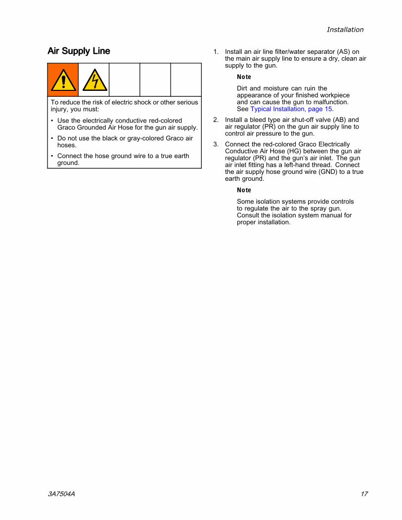
9. Connect the other end of the hose to the isolatedfluid supply as instructed in the isolation systemmanual. The conductive hose layer must begrounded at the isolation system.
Conductive hose layer (FC) must be groundedthrough its connection to the isolation system’sgrounded enclosure (CA) or groundedfence. To maintain grounding continuity, theconductive hose layer (FC) must be engagedin the ferrule when the strain relief nut istightened. Failure to properly install the hose inthe strain relief could result in an electric shock.
Figure 12 Shielded Fluid Hose Connection atNon-Graco Isolation Enclosure
16 3A7504A
Installation
AirAirAir SupplySupplySupply LineLineLine
To reduce the risk of electric shock or other seriousinjury, you must:
• Use the electrically conductive red-coloredGraco Grounded Air Hose for the gun air supply.
• Do not use the black or gray-colored Graco airhoses.
• Connect the hose ground wire to a true earthground.
1. Install an air line filter/water separator (AS) onthe main air supply line to ensure a dry, clean airsupply to the gun.
Note
Dirt and moisture can ruin theappearance of your finished workpieceand can cause the gun to malfunction.See Typical Installation, page 15.
2. Install a bleed type air shut-off valve (AB) andair regulator (PR) on the gun air supply line tocontrol air pressure to the gun.
3. Connect the red-colored Graco ElectricallyConductive Air Hose (HG) between the gun airregulator (PR) and the gun’s air inlet. The gunair inlet fitting has a left-hand thread. Connectthe air supply hose ground wire (GND) to a trueearth ground.
Note
Some isolation systems provide controlsto regulate the air to the spray gun.Consult the isolation system manual forproper installation.
3A7504A 17
Installation
GroundingGroundingGrounding
The equipment must be grounded to reduce therisk of static sparking and electric shock. Electricor static sparking can cause fumes to ignite orexplode. Improper grounding can cause electricshock. Ground all equipment, personnel, objectsbeing sprayed, and conductive objects in or closeto the spray area. The resistance must not exceed1 megohm. Grounding provides an escape wirefor the electric current.
When operating the electrostatic gun, anyungrounded objects (such as people, containers, andtools) in the spray location can become electricallycharged.
The following are minimum grounding requirementsfor a basic electrostatic system. Your system mayinclude other equipment or objects which must begrounded. Your system must be connected to atrue earth ground. Check ground connections daily.Check your local electrical codes and regulations fordetailed grounding instructions.
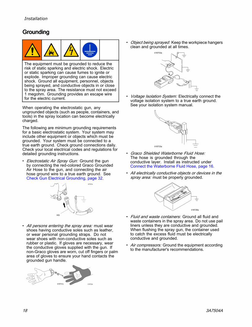
• Electrostatic Air Spray Gun: Ground the gunby connecting the red-colored Graco GroundedAir Hose to the gun, and connecting the airhose ground wire to a true earth ground. SeeCheck Gun Electrical Grounding, page 32.
• All persons entering the spray area: must wearshoes having conductive soles such as leather,or wear personal grounding straps. Do notwear shoes with non-conductive soles such asrubber or plastic. If gloves are necessary, wearthe conductive gloves supplied with the gun. Ifnon-Graco gloves are worn, cut off fingers or palmarea of gloves to ensure your hand contacts thegrounded gun handle.
• Object being sprayed: Keep the workpiece hangersclean and grounded at all times.
• Voltage Isolation System: Electrically connect thevoltage isolation system to a true earth ground.See your isolation system manual.
• Graco Shielded Waterborne Fluid Hose:The hose is grounded through theconductive layer. Install as instructed underConnect the Waterborne Fluid Hose, page 16.
• All electrically conductive objects or devices in thespray area: must be properly grounded.
• Fluid and waste containers: Ground all fluid andwaste containers in the spray area. Do not use pailliners unless they are conductive and grounded.When flushing the spray gun, the container usedto catch the excess fluid must be electricallyconductive and grounded.
• Air compressors: Ground the equipment accordingto the manufacturer's recommendations.
18 3A7504A
Installation
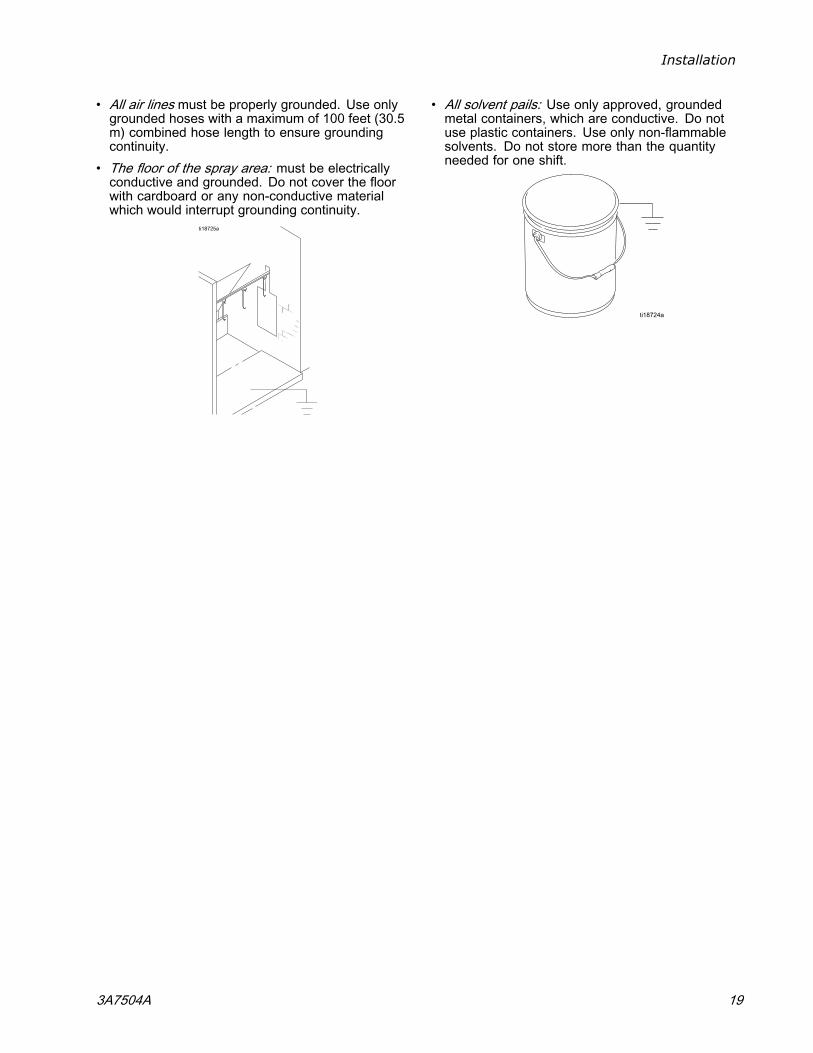
• All air lines must be properly grounded. Use onlygrounded hoses with a maximum of 100 feet (30.5m) combined hose length to ensure groundingcontinuity.
• The floor of the spray area: must be electricallyconductive and grounded. Do not cover the floorwith cardboard or any non-conductive materialwhich would interrupt grounding continuity.
• All solvent pails: Use only approved, groundedmetal containers, which are conductive. Do notuse plastic containers. Use only non-flammablesolvents. Do not store more than the quantityneeded for one shift.
3A7504A 19
Gun Setup
GunGunGun SetupSetupSetup
GunGunGun SetupSetupSetup ProcedureProcedureProcedure
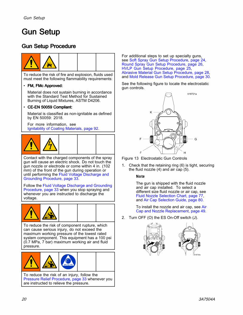
To reduce the risk of fire and explosion, fluids usedmust meet the following flammability requirements:
• FM,FM,FM, FMcFMcFMc Approved:Approved:Approved:Material does not sustain burning in accordancewith the Standard Test Method for SustainedBurning of Liquid Mixtures, ASTM D4206.
• CECECE---ENENEN 500595005950059 Compliant:Compliant:Compliant:Material is classified as non-ignitable as definedby EN 50059: 2018.For more information, seeIgnitability of Coating Materials, page 92.
Contact with the charged components of the spraygun will cause an electric shock. Do not touch thegun nozzle or electrode or come within 4 in. (102mm) of the front of the gun during operation oruntil performing the Fluid Voltage Discharge andGrounding Procedure, page 33.
Follow the Fluid Voltage Discharge and GroundingProcedure, page 33 when you stop spraying andwhenever you are instructed to discharge thevoltage.
To reduce the risk of component rupture, whichcan cause serious injury, do not exceed themaximum working pressure of the lowest ratedsystem component. This equipment has a 100 psi(0.7 MPa, 7 bar) maximum working air and fluidpressure.
To reduce the risk of an injury, follow thePressure Relief Procedure, page 33 whenever youare instructed to relieve the pressure.
For additional steps to set up specialty guns,see Soft Spray Gun Setup Procedure, page 24,Round Spray Gun Setup Procedure, page 26,HVLP Gun Setup Procedure, page 25,Abrasive Material Gun Setup Procedure, page 28,and Mold Release Gun Setup Procedure, page 30.
See the following figure to locate the electrostaticgun controls.
Figure 13 Electrostatic Gun Controls
1. Check that the retaining ring (6) is tight, securingthe fluid nozzle (4) and air cap (5).
Note
The gun is shipped with the fluid nozzleand air cap installed. To select adifferent size fluid nozzle or air cap, seeFluid Nozzle Selection Chart, page 77,and Air Cap Selection Guide, page 80.
To install the nozzle and air cap, see AirCap and Nozzle Replacement, page 49.
2. Turn OFF (O) the ES On-Off switch (J).
20 3A7504A
Gun Setup
3. Shut off the bleed-type air shutoff valve (AB) tothe gun.
4. Check gun resistance. Follow the steps inTest Gun Resistance, page 39.
5. Connect the waterborne hose. Follow the stepsin Connect the Waterborne Fluid Hose, page 16.
6. Connect the red Graco grounded air hoseto the gun air inlet. The gun air inlet fittinghas left-hand threads. Follow the steps inAir Supply Line, page 17.
7. Follow the steps in Grounding, page 18.8. Follow the steps in
Check Gun Electrical Grounding, page 32.Reading must be less than 100 ohms.
9. Connect the exhaust tube and secure with theclamp provided.
10. Flush if needed. Follow the steps inFlushing, page 35.
11. Position the air cap as needed.
12. Fully open the fan air adjustment valve (F)counterclockwise.
13. Fully open the fluid adjustment valve (H)counterclockwise.
3A7504A 21
Gun Setup
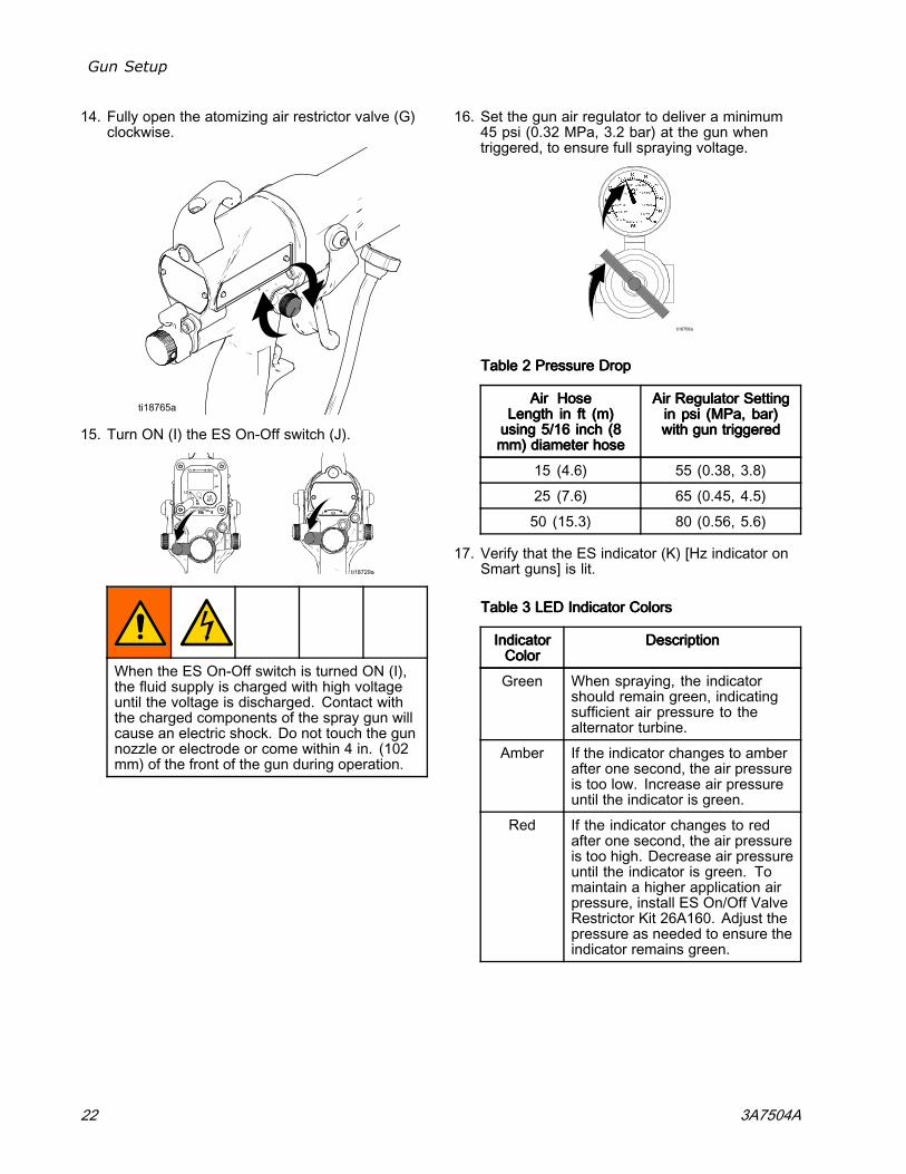
14. Fully open the atomizing air restrictor valve (G)clockwise.
15. Turn ON (I) the ES On-Off switch (J).
When the ES On-Off switch is turned ON (I),the fluid supply is charged with high voltageuntil the voltage is discharged. Contact withthe charged components of the spray gun willcause an electric shock. Do not touch the gunnozzle or electrode or come within 4 in. (102mm) of the front of the gun during operation.
16. Set the gun air regulator to deliver a minimum45 psi (0.32 MPa, 3.2 bar) at the gun whentriggered, to ensure full spraying voltage.
TableTableTable 222 PressurePressurePressure DropDropDrop
AirAirAir HoseHoseHoseLengthLengthLength ininin ftftft (m)(m)(m)usingusingusing 5/165/165/16 inchinchinch (8(8(8mm)mm)mm) diameterdiameterdiameter hosehosehose
AirAirAir RegulatorRegulatorRegulator SettingSettingSettingininin psipsipsi (MPa,(MPa,(MPa, bar)bar)bar)withwithwith gungungun triggeredtriggeredtriggered
15 (4.6) 55 (0.38, 3.8)
25 (7.6) 65 (0.45, 4.5)
50 (15.3) 80 (0.56, 5.6)
17. Verify that the ES indicator (K) [Hz indicator onSmart guns] is lit.
TableTableTable 333 LEDLEDLED IndicatorIndicatorIndicator ColorsColorsColors
IndicatorIndicatorIndicatorColorColorColor
DescriptionDescriptionDescription
Green When spraying, the indicatorshould remain green, indicatingsufficient air pressure to thealternator turbine.
Amber If the indicator changes to amberafter one second, the air pressureis too low. Increase air pressureuntil the indicator is green.
Red If the indicator changes to redafter one second, the air pressureis too high. Decrease air pressureuntil the indicator is green. Tomaintain a higher application airpressure, install ES On/Off ValveRestrictor Kit 26A160. Adjust thepressure as needed to ensure theindicator remains green.
22 3A7504A
Gun Setup
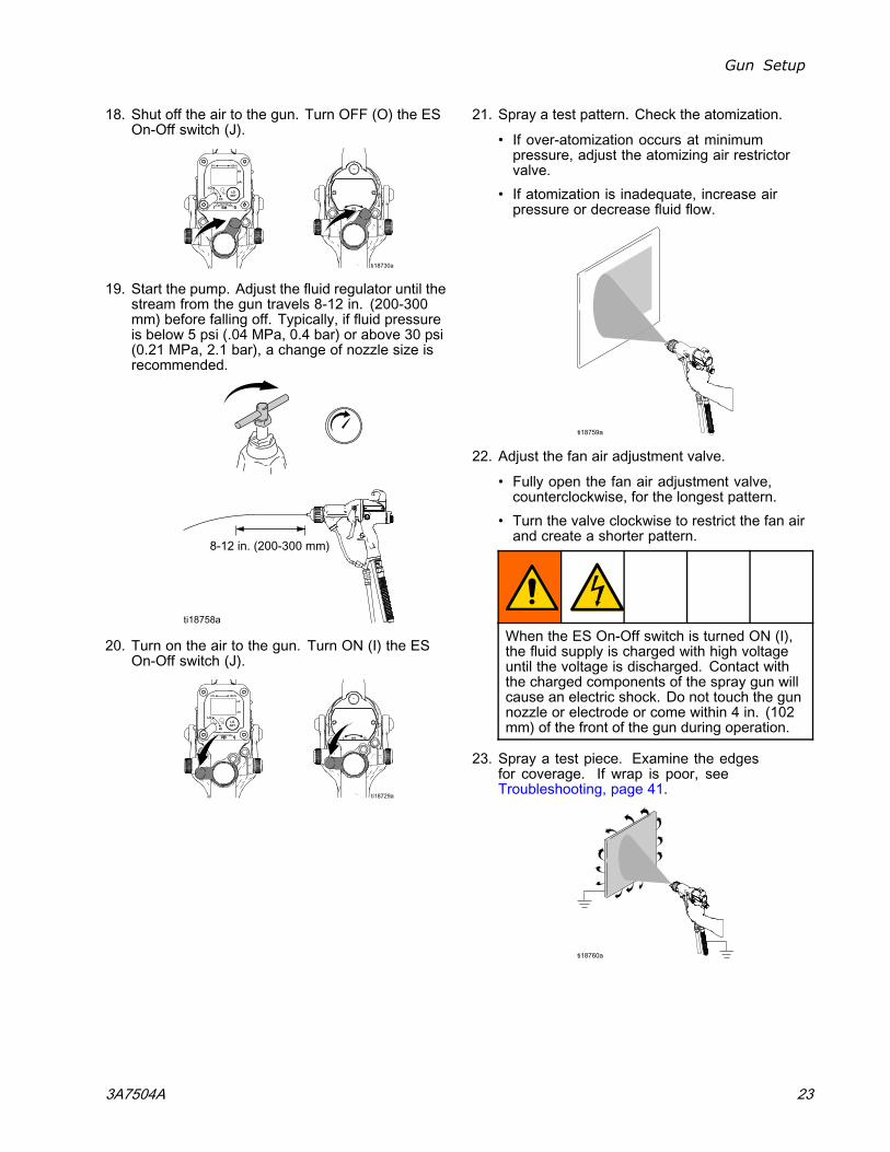
18. Shut off the air to the gun. Turn OFF (O) the ESOn-Off switch (J).
19. Start the pump. Adjust the fluid regulator until thestream from the gun travels 8-12 in. (200-300mm) before falling off. Typically, if fluid pressureis below 5 psi (.04 MPa, 0.4 bar) or above 30 psi(0.21 MPa, 2.1 bar), a change of nozzle size isrecommended.
20. Turn on the air to the gun. Turn ON (I) the ESOn-Off switch (J).
21. Spray a test pattern. Check the atomization.
• If over-atomization occurs at minimumpressure, adjust the atomizing air restrictorvalve.
• If atomization is inadequate, increase airpressure or decrease fluid flow.
22. Adjust the fan air adjustment valve.
• Fully open the fan air adjustment valve,counterclockwise, for the longest pattern.
• Turn the valve clockwise to restrict the fan airand create a shorter pattern.
When the ES On-Off switch is turned ON (I),the fluid supply is charged with high voltageuntil the voltage is discharged. Contact withthe charged components of the spray gun willcause an electric shock. Do not touch the gunnozzle or electrode or come within 4 in. (102mm) of the front of the gun during operation.
23. Spray a test piece. Examine the edgesfor coverage. If wrap is poor, seeTroubleshooting, page 41.
3A7504A 23
Gun Setup
SoftSoftSoft SpraySpraySpray GunGunGun SetupSetupSetup ProcedureProcedureProcedure
To convert a gun to achieve a soft spray pattern forsmall or lightweight parts, do the following:
1. Install a soft spray air cap. SeeAir Cap Selection Guide, page 80.
2. For best results, install a 1.0 mmor 1.2 mm fluid nozzle. SeeFluid Nozzle Selection Chart, page 77.
3. Follow steps 1–13 in theGun Setup Procedure, page 20.
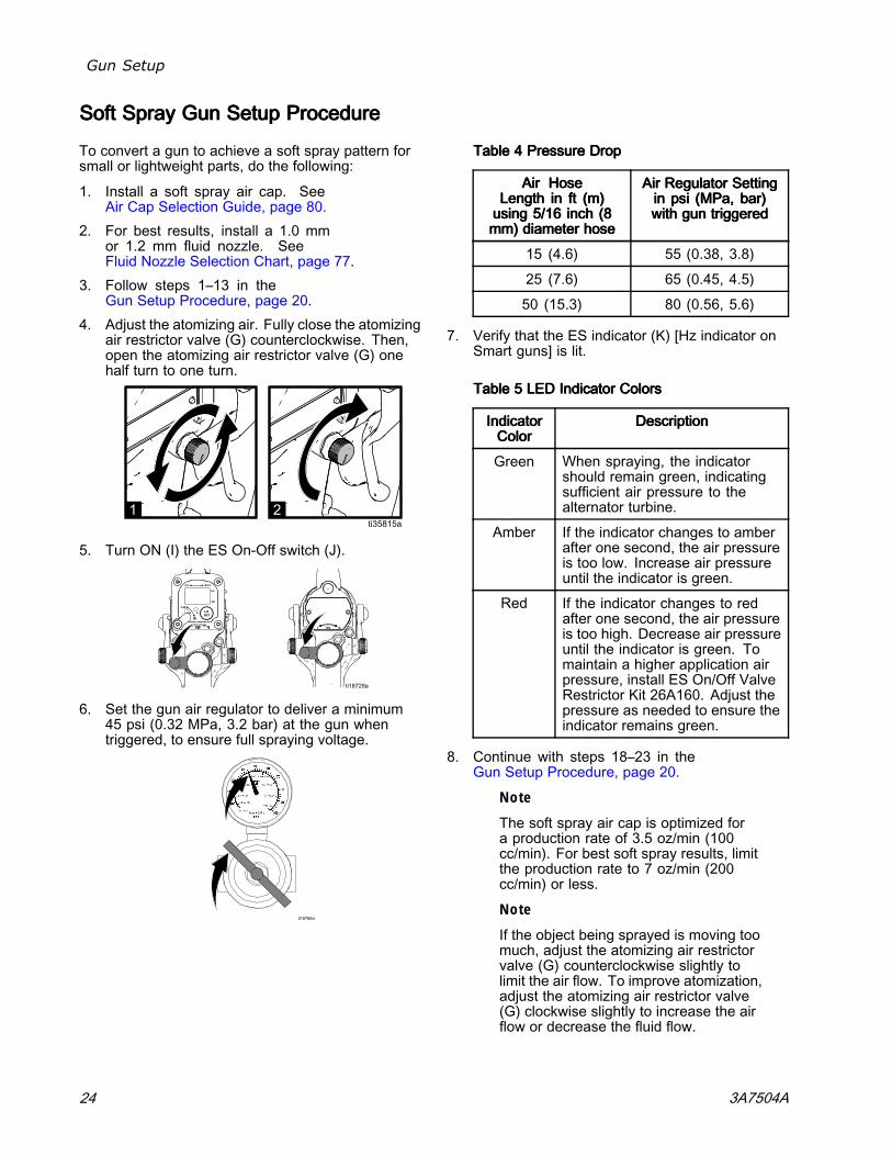
4. Adjust the atomizing air. Fully close the atomizingair restrictor valve (G) counterclockwise. Then,open the atomizing air restrictor valve (G) onehalf turn to one turn.
5. Turn ON (I) the ES On-Off switch (J).
6. Set the gun air regulator to deliver a minimum45 psi (0.32 MPa, 3.2 bar) at the gun whentriggered, to ensure full spraying voltage.
TableTableTable 444 PressurePressurePressure DropDropDrop
AirAirAir HoseHoseHoseLengthLengthLength ininin ftftft (m)(m)(m)usingusingusing 5/165/165/16 inchinchinch (8(8(8mm)mm)mm) diameterdiameterdiameter hosehosehose
AirAirAir RegulatorRegulatorRegulator SettingSettingSettingininin psipsipsi (MPa,(MPa,(MPa, bar)bar)bar)withwithwith gungungun triggeredtriggeredtriggered
15 (4.6) 55 (0.38, 3.8)
25 (7.6) 65 (0.45, 4.5)
50 (15.3) 80 (0.56, 5.6)
7. Verify that the ES indicator (K) [Hz indicator onSmart guns] is lit.
TableTableTable 555 LEDLEDLED IndicatorIndicatorIndicator ColorsColorsColors
IndicatorIndicatorIndicatorColorColorColor
DescriptionDescriptionDescription
Green When spraying, the indicatorshould remain green, indicatingsufficient air pressure to thealternator turbine.
Amber If the indicator changes to amberafter one second, the air pressureis too low. Increase air pressureuntil the indicator is green.
Red If the indicator changes to redafter one second, the air pressureis too high. Decrease air pressureuntil the indicator is green. Tomaintain a higher application airpressure, install ES On/Off ValveRestrictor Kit 26A160. Adjust thepressure as needed to ensure theindicator remains green.
8. Continue with steps 18–23 in theGun Setup Procedure, page 20.
Note
The soft spray air cap is optimized fora production rate of 3.5 oz/min (100cc/min). For best soft spray results, limitthe production rate to 7 oz/min (200cc/min) or less.
Note
If the object being sprayed is moving toomuch, adjust the atomizing air restrictorvalve (G) counterclockwise slightly tolimit the air flow. To improve atomization,adjust the atomizing air restrictor valve(G) clockwise slightly to increase the airflow or decrease the fluid flow.
24 3A7504A
Gun Setup
HVLPHVLPHVLP GunGunGun SetupSetupSetup ProcedureProcedureProcedure
To spray high pressure low volume (HVLP) sprayguns, air pressure at the air cap must be 10 PSI (0.07MPa, 0.7 bar) or less. To set up an HVLP gun, dothe following:
1. Install an HVLP air cap. SeeAir Cap Selection Guide, page 80.
2. Follow steps 1–11 in theGun Setup Procedure, page 20.
3. Fully open the fluid adjustment valve (H)counterclockwise.
4. Adjust the air in the air cap.
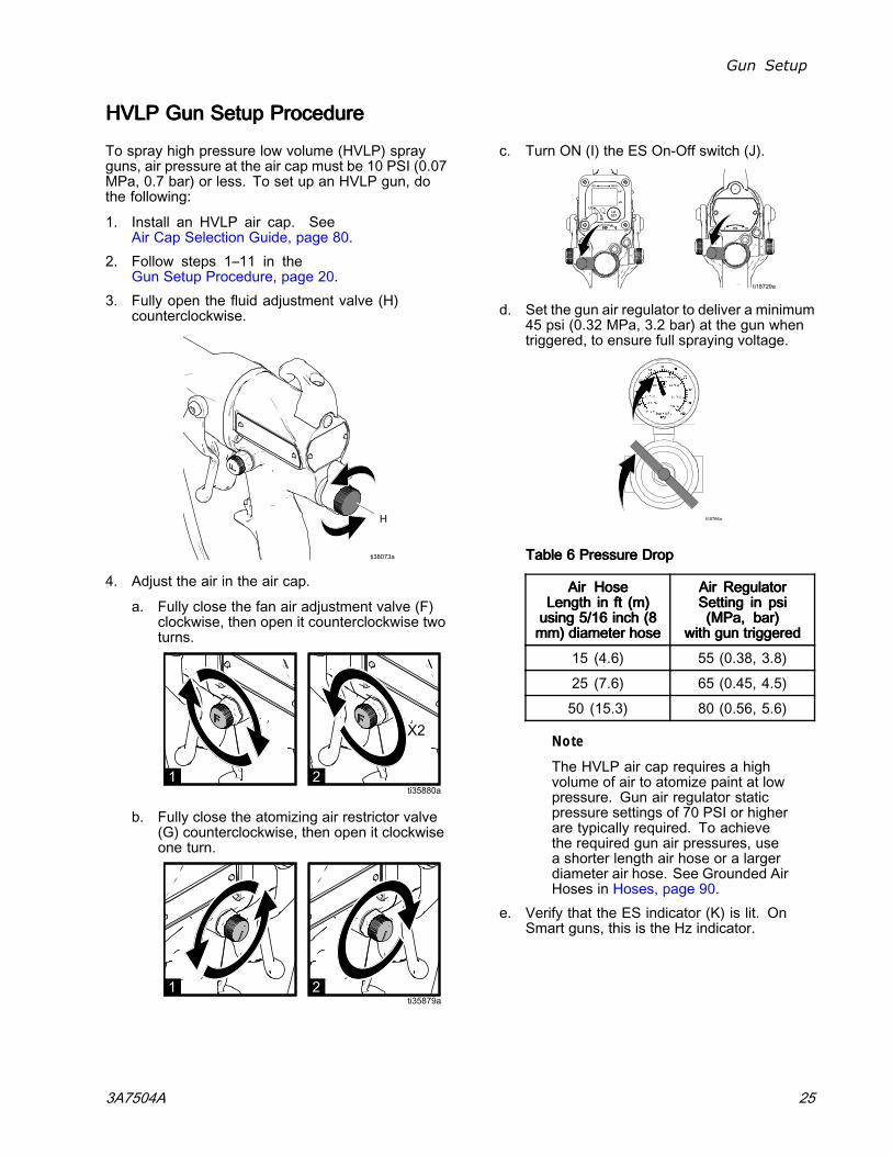
a. Fully close the fan air adjustment valve (F)clockwise, then open it counterclockwise twoturns.
b. Fully close the atomizing air restrictor valve(G) counterclockwise, then open it clockwiseone turn.
c. Turn ON (I) the ES On-Off switch (J).
d. Set the gun air regulator to deliver a minimum45 psi (0.32 MPa, 3.2 bar) at the gun whentriggered, to ensure full spraying voltage.
TableTableTable 666 PressurePressurePressure DropDropDrop
AirAirAir HoseHoseHoseLengthLengthLength ininin ftftft (m)(m)(m)usingusingusing 5/165/165/16 inchinchinch (8(8(8mm)mm)mm) diameterdiameterdiameter hosehosehose
AirAirAir RegulatorRegulatorRegulatorSettingSettingSetting ininin psipsipsi(MPa,(MPa,(MPa, bar)bar)bar)
withwithwith gungungun triggeredtriggeredtriggered
15 (4.6) 55 (0.38, 3.8)
25 (7.6) 65 (0.45, 4.5)
50 (15.3) 80 (0.56, 5.6)
Note
The HVLP air cap requires a highvolume of air to atomize paint at lowpressure. Gun air regulator staticpressure settings of 70 PSI or higherare typically required. To achievethe required gun air pressures, usea shorter length air hose or a largerdiameter air hose. See Grounded AirHoses in Hoses, page 90.
e. Verify that the ES indicator (K) is lit. OnSmart guns, this is the Hz indicator.
3A7504A 25
Gun Setup
TableTableTable 777 LEDLEDLED IndicatorIndicatorIndicator ColorsColorsColors
IndicatorIndicatorIndicatorColorColorColor
DescriptionDescriptionDescription
Green When spraying, the indicatorshould remain green, indicatingsufficient air pressure to thealternator turbine.
Amber If the indicator changes toamber after one second, the airpressure is too low. Increaseair pressure until the indicatoris green.
Red If the indicator changes tored after one second, the airpressure is too high. Decreaseair pressure until the indicatoris green. To maintain a higherapplication air pressure, installES On/Off Valve Restrictor Kit26A160. Adjust the pressureas needed to ensure theindicator remains green.
f. Verify that the air cap pressures meet HVLPrequirements of 10 PSI (0.07 MPa, 0.7bar) or less using the HVLP verification kit25E919. See manual 3A6833. Adjust thefan air adjustment valve (F) and atomizingair restrictor valve to achieve 10 PSI or lessas needed.
g. Verify that the ES indicator (K) [Hz indicatoron Smart guns] remains green.
5. Continue with steps 18–23 in theGun Setup Procedure, page 20.
RoundRoundRound SpraySpraySpray GunGunGun SetupSetupSetup ProcedureProcedureProcedure
To achieve a round spray pattern, do the following:
1. Install a round spray kit. See Round SprayAccessories in Gun Accessories, page 88. Toachieve a soft pattern for small parts or increasedtransfer efficiency, select the medium pattern orsmall pattern models.
2. Follow steps 1–11 in theGun Setup Procedure, page 20.
3. Fully open the fluid adjustment valve (H)counterclockwise.
4. Adjust the air in the air cap.
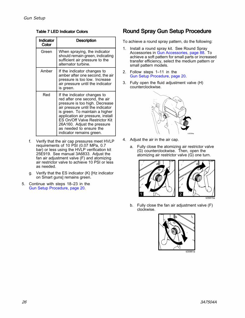
a. Fully close the atomizing air restrictor valve(G) counterclockwise. Then, open theatomizing air restrictor valve (G) one turn.
b. Fully close the fan air adjustment valve (F)clockwise.
26 3A7504A
Gun Setup
5. Turn ON (I) the ES On-Off switch (J).
6. Set the gun air regulator to deliver a minimum45 psi (0.32 MPa, 3.2 bar) at the gun whentriggered, to ensure full spraying voltage.
TableTableTable 888 PressurePressurePressure DropDropDrop
AirAirAir HoseHoseHoseLengthLengthLength ininin ftftft (m)(m)(m)usingusingusing 5/165/165/16 inchinchinch (8(8(8mm)mm)mm) diameterdiameterdiameter hosehosehose
AirAirAir RegulatorRegulatorRegulator SettingSettingSettingininin psipsipsi (MPa,(MPa,(MPa, bar)bar)bar)withwithwith gungungun triggeredtriggeredtriggered
15 (4.6) 55 (0.38, 3.8)
25 (7.6) 65 (0.45, 4.5)
50 (15.3) 80 (0.56, 5.6)
7. Verify that the ES indicator (K) [Hz indicator onSmart guns] is lit.
TableTableTable 999 LEDLEDLED IndicatorIndicatorIndicator ColorsColorsColors
IndicatorIndicatorIndicatorColorColorColor
DescriptionDescriptionDescription
Green When spraying, the indicatorshould remain green, indicatingsufficient air pressure to thealternator turbine.
Amber If the indicator changes to amberafter one second, the air pressureis too low. Increase air pressureuntil the indicator is green.
Red If the indicator changes to redafter one second, the air pressureis too high. Decrease air pressureuntil the indicator is green. Tomaintain a higher application airpressure, install ES On/Off ValveRestrictor Kit 26A160. Adjust thepressure as needed to ensure theindicator remains green.
8. Shut off the air to the gun. Turn OFF (O) the ESOn-Off switch (J).
9. Start the pump. Adjust the fluid regulator toachieve the production rate that you want.
Note
The round spray air cap is optimizedfor a production rate of 5 oz/min (150cc/min). For best round spray results,limit the production rate to 10 oz/min(300 cc/min) or less.
3A7504A 27
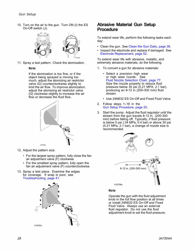
Gun Setup
10. Turn on the air to the gun. Turn ON (I) the ESOn-Off switch (J).
11. Spray a test pattern. Check the atomization.
Note
If the atomization is too fine, or if theobject being sprayed is moving toomuch, adjust the atomizing air restrictorvalve (G) counterclockwise slightly tolimit the air flow. To improve atomization,adjust the atomizing air restrictor valve(G) clockwise slightly to increase the airflow or decrease the fluid flow.
12. Adjust the pattern size.
• For the largest spray pattern, fully close the fanair adjustment valve (F) clockwise.
• For the smallest spray pattern, fully open thefan air adjustment valve (F) counterclockwise.
13. Spray a test piece. Examine the edgesfor coverage. If wrap is poor, seeTroubleshooting, page 41.
AbrasiveAbrasiveAbrasive MaterialMaterialMaterial GunGunGun SetupSetupSetupProcedureProcedureProcedure
To extend wear life, perform the following tasks eachday:
• Clean the gun. See Clean the Gun Daily, page 36.• Inspect the electrode and replace if damaged. SeeElectrode Replacement, page 52.
To extend wear life with abrasive, metallic, andextremely abrasive materials, do the following:
1. To convert a gun for abrasive materials:
• Select a precision high wearor high wear nozzle. SeeFluid Nozzle Selection Chart, page 77.Size the nozzle properly to reduce fluidpressure below 30 psi (0.21 MPA, 2.1 bar),producing an 8-12 in (200-300 mm) fluidstream.
• Use 24N632 ES On-Off and Fixed Fluid Valve.2. Follow steps 1–18 in the
Gun Setup Procedure, page 20.3. Start the pump. Adjust the fluid regulator until the
stream from the gun travels 8-12 in. (200-300mm) before falling off. Typically, if fluid pressureis below 5 psi (.04 MPa, 0.4 bar) or above 30 psi(0.21 MPa, 2.1 bar), a change of nozzle size isrecommended.
Note
Operate the gun with the fluid adjustmentknob in the full flow position at all timesor install 24N632 ES On-Off and FixedFluid Valve. Always use an externalfluid regulator. Do not use the fluidadjustment knob to set the fluid pressure.
28 3A7504A
Gun Setup
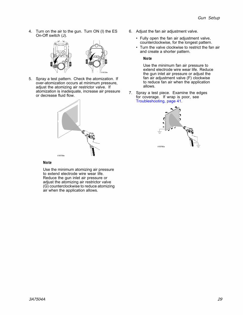
4. Turn on the air to the gun. Turn ON (I) the ESOn-Off switch (J).
5. Spray a test pattern. Check the atomization. Ifover-atomization occurs at minimum pressure,adjust the atomizing air restrictor valve. Ifatomization is inadequate, increase air pressureor decrease fluid flow.
Note
Use the minimum atomizing air pressureto extend electrode wire wear life.Reduce the gun inlet air pressure oradjust the atomizing air restrictor valve(G) counterclockwise to reduce atomizingair when the application allows.
6. Adjust the fan air adjustment valve.
• Fully open the fan air adjustment valve,counterclockwise, for the longest pattern.
• Turn the valve clockwise to restrict the fan airand create a shorter pattern.
Note
Use the minimum fan air pressure toextend electrode wire wear life. Reducethe gun inlet air pressure or adjust thefan air adjustment valve (F) clockwiseto reduce fan air when the applicationallows.
7. Spray a test piece. Examine the edgesfor coverage. If wrap is poor, seeTroubleshooting, page 41.
3A7504A 29
Gun Setup
MoldMoldMold ReleaseReleaseRelease GunGunGun SetupSetupSetup ProcedureProcedureProcedure
To set up a mold release gun, do the following:
1. Model L60M19 Mold Release Gun is suppliedwith Part No. 24N748 Nozzle, 24N727 AirCap, and a spray tip of choice. If you requirea different size spray tip, follow the steps inSpray Tip Selection Chart (Model L60M19MRG Gun Only), page 86, or consult withyour Graco distributor. To install the tip, seeAir Cap, Spray Tip, and Nozzle Replacement(Model L60M19), page 50.
2. Follow steps 2–10 in theGun Setup Procedure, page 20.
3. Use the Spray Tip Selection Chart (ModelL60M19 MRG Gun Only), page 86, as a guidefor selecting the appropriate spray tip for yourapplication. The fluid output and pattern widthdepend on the size of the spray tip, the fluidviscosity, and the fluid pressure.
4. Align the spray tip tab with the groove in the aircap. Install the tip.
5. Install the air cap and retaining ring. Orientatethe air cap and tighten the retaining ring securely.
6. Close the atomizing air adjustment valve (G) andthe fan air adjustment valve (F).
7. Check that the ES On-Off switch is OFF (O).
8. Start the pump. Set the fluid regulator to 400 psi(2.8 MPa, 28 bar).
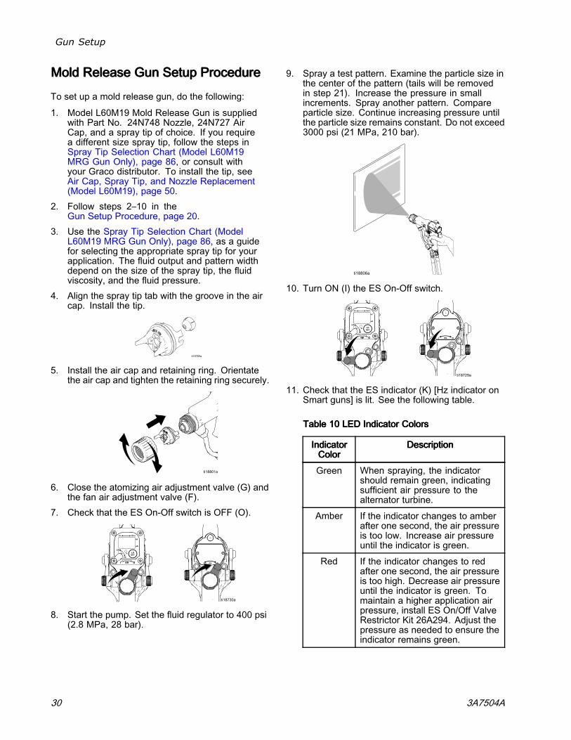
9. Spray a test pattern. Examine the particle size inthe center of the pattern (tails will be removedin step 21). Increase the pressure in smallincrements. Spray another pattern. Compareparticle size. Continue increasing pressure untilthe particle size remains constant. Do not exceed3000 psi (21 MPa, 210 bar).
10. Turn ON (I) the ES On-Off switch.
11. Check that the ES indicator (K) [Hz indicator onSmart guns] is lit. See the following table.
TableTableTable 101010 LEDLEDLED IndicatorIndicatorIndicator ColorsColorsColors
IndicatorIndicatorIndicatorColorColorColor
DescriptionDescriptionDescription
Green When spraying, the indicatorshould remain green, indicatingsufficient air pressure to thealternator turbine.
Amber If the indicator changes to amberafter one second, the air pressureis too low. Increase air pressureuntil the indicator is green.
Red If the indicator changes to redafter one second, the air pressureis too high. Decrease air pressureuntil the indicator is green. Tomaintain a higher application airpressure, install ES On/Off ValveRestrictor Kit 26A294. Adjust thepressure as needed to ensure theindicator remains green.
30 3A7504A
Gun Setup
12. Set the gun air regulator to deliver a minimumof 45 psi (0.32 MPa, 3.2 bar) at the gun whentriggered, to ensure full spraying voltage. Seethe table below.
TableTableTable 111111 PressurePressurePressure DropDropDrop
AirAirAir HoseHoseHoseLengthLengthLength ininin ftftft (m)(m)(m)(using(using(using 5/165/165/16 in.in.in. [8[8[8mm]mm]mm] diameterdiameterdiameter hose)hose)hose)
AirAirAir RegulatorRegulatorRegulator SettingSettingSettingininin psipsipsi (MPa,(MPa,(MPa, bar)bar)bar)[with[with[with gungungun triggered]triggered]triggered]
15 (4.6) 52 (0.36, 3.6)
25 (7.6) 57 (0.40, 4.0)
50 (15.3) 68 (0.47, 4.7)
75 (22.9) 80 (0.56, 5.6)
100 (30.5) 90 (0.63, 6.3)
13. Turn the atomizing air adjustment valvecounterclockwise until any tails disappear.
14. If desired atomization is not achieved, changethe tip size. The smaller the tip orifice, the finerthe atomization.
15. Spray a test piece. Examine the edgesfor coverage. If wrap is poor, seeTroubleshooting, page 41.
Note
If a narrower pattern is needed occasionally,open the fan air adjustment valve slightly.(Excessive fan air flow can cause paintbuildup on the air cap.)
3A7504A 31
Gun Setup
CheckCheckCheck GunGunGun ElectricalElectricalElectrical GroundingGroundingGrounding
Megohmmeter Part No. 241079 is not approvedfor use in a hazardous area. (In Figure 14, itemAA.) To reduce the risk of sparking, do not usethe megohmmeter to check electrical groundingunless:
• The gun has been removed from the hazardousarea;
• Or all spraying devices in the hazardous areaare turned off, ventilation fans in the hazardousarea are operating, and there are no flammablevapors in the area (such as open solventcontainers or fumes from spraying).
Failure to follow this warning could cause fire,explosion, and electric shock and result in seriousinjury and property damage.
Graco Part No. 241079 Megohmmeter is availableas an accessory to check that the gun is properlygrounded.
1. Have a qualified electrician check the electricalgrounding continuity of the spray gun and airhose.
2. Turn OFF (O) the ES On-Off switch.
3. Turn off the air and fluid supply to the gun. Followthe Pressure Relief Procedure, page 33. Thefluid hose must not have any fluid in it.
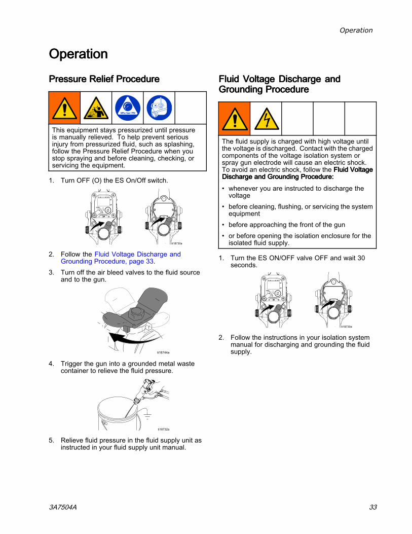
4. Disconnect the fluid hose.5. Make sure the red-colored grounded air hose
(HG) is connected and the hose ground wire isconnected to a true earth ground.
6. Measure the resistance between the gunhandle (BB) and a true earth ground (CC). Theresistance should not exceed 100 ohms.
Figure 14 Check Gun Electrical Grounding7. If the resistance is greater than 100 ohms, check
the tightness of the ground connections and besure the air hose ground wire is connected to atrue earth ground. If the resistance is still toohigh, replace the air hose.
FlushFlushFlush BeforeBeforeBefore UsingUsingUsing EquipmentEquipmentEquipment
The equipment was tested in fluid at the factory. Toavoid contaminating your fluid, flush the equipmentwith a compatible solvent before using the equipment.Follow the steps in Flushing, page 35.
32 3A7504A
Operation
OperationOperationOperation
PressurePressurePressure ReliefReliefRelief ProcedureProcedureProcedure
This equipment stays pressurized until pressureis manually relieved. To help prevent seriousinjury from pressurized fluid, such as splashing,follow the Pressure Relief Procedure when youstop spraying and before cleaning, checking, orservicing the equipment.
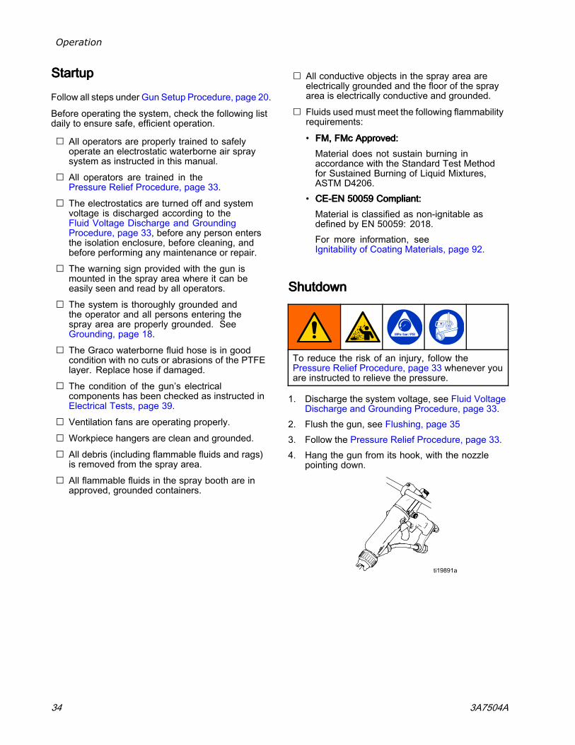
1. Turn OFF (O) the ES On/Off switch.
2. Follow the Fluid Voltage Discharge andGrounding Procedure, page 33.
3. Turn off the air bleed valves to the fluid sourceand to the gun.
4. Trigger the gun into a grounded metal wastecontainer to relieve the fluid pressure.
5. Relieve fluid pressure in the fluid supply unit asinstructed in your fluid supply unit manual.
FluidFluidFluid VoltageVoltageVoltage DischargeDischargeDischarge andandandGroundingGroundingGrounding ProcedureProcedureProcedure
The fluid supply is charged with high voltage untilthe voltage is discharged. Contact with the chargedcomponents of the voltage isolation system orspray gun electrode will cause an electric shock.To avoid an electric shock, follow the FluidFluidFluid VoltageVoltageVoltageDischargeDischargeDischarge andandand GroundingGroundingGrounding Procedure:Procedure:Procedure:
• whenever you are instructed to discharge thevoltage
• before cleaning, flushing, or servicing the systemequipment
• before approaching the front of the gun• or before opening the isolation enclosure for theisolated fluid supply.
1. Turn the ES ON/OFF valve OFF and wait 30seconds.
2. Follow the instructions in your isolation systemmanual for discharging and grounding the fluidsupply.
3A7504A 33
Operation
StartupStartupStartup
Follow all steps under Gun Setup Procedure, page 20.
Before operating the system, check the following listdaily to ensure safe, efficient operation.
⃞ All operators are properly trained to safelyoperate an electrostatic waterborne air spraysystem as instructed in this manual.
⃞ All operators are trained in thePressure Relief Procedure, page 33.
⃞ The electrostatics are turned off and systemvoltage is discharged according to theFluid Voltage Discharge and GroundingProcedure, page 33, before any person entersthe isolation enclosure, before cleaning, andbefore performing any maintenance or repair.
⃞ The warning sign provided with the gun ismounted in the spray area where it can beeasily seen and read by all operators.
⃞ The system is thoroughly grounded andthe operator and all persons entering thespray area are properly grounded. SeeGrounding, page 18.
⃞ The Graco waterborne fluid hose is in goodcondition with no cuts or abrasions of the PTFElayer. Replace hose if damaged.
⃞ The condition of the gun’s electricalcomponents has been checked as instructed inElectrical Tests, page 39.
⃞ Ventilation fans are operating properly.⃞ Workpiece hangers are clean and grounded.⃞ All debris (including flammable fluids and rags)
is removed from the spray area.⃞ All flammable fluids in the spray booth are in
approved, grounded containers.
⃞ All conductive objects in the spray area areelectrically grounded and the floor of the sprayarea is electrically conductive and grounded.
⃞ Fluids used must meet the following flammabilityrequirements:
• FM,FM,FM, FMcFMcFMc Approved:Approved:Approved:Material does not sustain burning inaccordance with the Standard Test Methodfor Sustained Burning of Liquid Mixtures,ASTM D4206.
• CECECE---ENENEN 500595005950059 Compliant:Compliant:Compliant:Material is classified as non-ignitable asdefined by EN 50059: 2018.For more information, seeIgnitability of Coating Materials, page 92.
ShutdownShutdownShutdown
To reduce the risk of an injury, follow thePressure Relief Procedure, page 33 whenever youare instructed to relieve the pressure.
1. Discharge the system voltage, see Fluid VoltageDischarge and Grounding Procedure, page 33.
2. Flush the gun, see Flushing, page 353. Follow the Pressure Relief Procedure, page 33.4. Hang the gun from its hook, with the nozzle
pointing down.
34 3A7504A

Maintenance
MaintenanceMaintenanceMaintenance
To reduce the risk of an injury, follow thePressure Relief Procedure, page 33, wheneveryou are instructed to relieve the pressure.
DailyDailyDaily CareCareCare andandand CleaningCleaningCleaning ChecklistChecklistChecklist
Check the following list daily upon completion ofequipment usage.
⃞ Flush the gun. See Flushing, page 35.⃞ Clean the fluid and air line filters.⃞ Clean the outside of the gun. See
Clean the Gun Daily, page 36.⃞ Clean the air cap and fluid nozzle daily,
at a minimum. Some applications requiremore frequent cleaning. Replace the spraytip and air cap if they are damaged. SeeClean the Gun Daily, page 36.
⃞ Check the electrode and replaceif broken or damaged. SeeElectrode Replacement, page 52.
⃞ Check for fluid leakage from the gun and fluidhoses. Tighten fittings or replace equipmentas needed.
⃞ Check electrical grounding. SeeCheck Gun Electrical Grounding, page 32.
FlushingFlushingFlushing
• Flush before changing fluids, before fluid can dryin the equipment, at the end of the day, beforestoring, and before repairing equipment.
• Flush at the lowest pressure possible. Checkconnectors for leaks and tighten as necessary.
To avoid fire and explosion, always groundequipment and waste container. To avoid staticsparking and injury from splashing, always flush atthe lowest possible pressure.
To reduce the risk of fire, explosion, or electricshock, turn OFF (O) the ES On-Off switch beforeflushing the gun.
Follow the Fluid Voltage Discharge and GroundingProcedure, page 33, before flushing.
Only flush, purge, or clean the gun with fluids thatmeet the following flammability requirements:
• FM,FM,FM, FMcFMcFMc Approved:Approved:Approved:Material does not sustain burning in accordancewith the Standard Test Method for SustainedBurning of Liquid Mixtures, ASTM D4206.
• CECECE---ENENEN 500595005950059 Compliant:Compliant:Compliant:Material is classified as non-ignitable as definedby EN 50059: 2018.For more information, seeIgnitability of Coating Materials, page 92.
NOTICENOTICENOTICEDo not use methylene chloride as a flushing orcleaning solvent with this gun as it will damagenylon components.
3A7504A 35
Maintenance
1. Turn OFF (O) the ES On-Off switch. Wait 30seconds for the voltage to bleed off.
2. Discharge the system voltage. Follow theFluid Voltage Discharge and GroundingProcedure, page 33.
3. Follow the Pressure Relief Procedure, page 33.
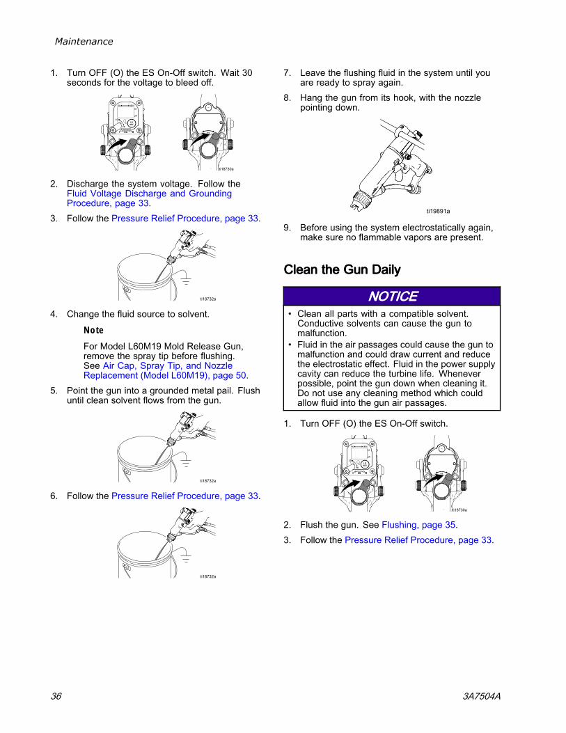
4. Change the fluid source to solvent.
Note
For Model L60M19 Mold Release Gun,remove the spray tip before flushing.See Air Cap, Spray Tip, and NozzleReplacement (Model L60M19), page 50.
5. Point the gun into a grounded metal pail. Flushuntil clean solvent flows from the gun.
6. Follow the Pressure Relief Procedure, page 33.
7. Leave the flushing fluid in the system until youare ready to spray again.
8. Hang the gun from its hook, with the nozzlepointing down.
9. Before using the system electrostatically again,make sure no flammable vapors are present.
CleanCleanClean thethethe GunGunGun DailyDailyDaily
NOTICENOTICENOTICE• Clean all parts with a compatible solvent.Conductive solvents can cause the gun tomalfunction.
• Fluid in the air passages could cause the gun tomalfunction and could draw current and reducethe electrostatic effect. Fluid in the power supplycavity can reduce the turbine life. Wheneverpossible, point the gun down when cleaning it.Do not use any cleaning method which couldallow fluid into the gun air passages.
1. Turn OFF (O) the ES On-Off switch.
2. Flush the gun. See Flushing, page 35.3. Follow the Pressure Relief Procedure, page 33.
36 3A7504A
Maintenance
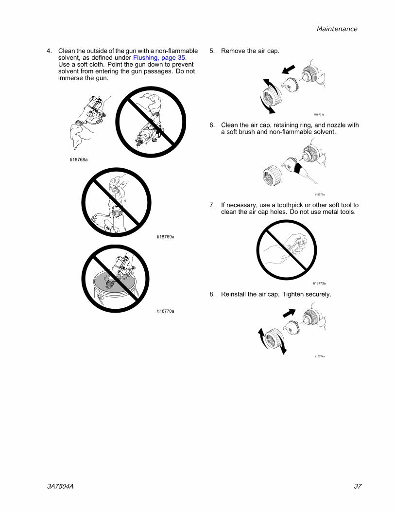
4. Clean the outside of the gun with a non-flammablesolvent, as defined under Flushing, page 35.Use a soft cloth. Point the gun down to preventsolvent from entering the gun passages. Do notimmerse the gun.
5. Remove the air cap.
6. Clean the air cap, retaining ring, and nozzle witha soft brush and non-flammable solvent.
7. If necessary, use a toothpick or other soft tool toclean the air cap holes. Do not use metal tools.
8. Reinstall the air cap. Tighten securely.
3A7504A 37
Maintenance
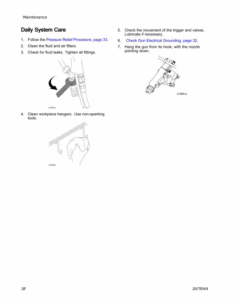
DailyDailyDaily SystemSystemSystem CareCareCare
1. Follow the Pressure Relief Procedure, page 33.2. Clean the fluid and air filters.3. Check for fluid leaks. Tighten all fittings.
4. Clean workpiece hangers. Use non-sparkingtools.
5. Check the movement of the trigger and valves.Lubricate if necessary.
6. Check Gun Electrical Grounding, page 32.7. Hang the gun from its hook, with the nozzle
pointing down.
38 3A7504A
Electrical Tests
ElectricalElectricalElectrical TestsTestsTestsElectrical components inside the gun affectperformance and safety. Use the followingprocedures to test the condition of the power supplyand gun body, and electrical continuity betweencomponents.
Use megohmmeter Part No. 241079 (AA) and anapplied voltage of 500 V. Connect the leads asshown.
Megohmmeter Part No. 241079 is not approvedfor use in a hazardous area. (In Figure 15, itemAA.) To reduce the risk of sparking, do not usethe megohmmeter to check electrical groundingunless:
• The gun has been removed from the hazardousarea;
• Or all spraying devices in the hazardous areaare turned off, ventilation fans in the hazardousarea are operating, and there are no flammablevapors in the area (such as open solventcontainers or fumes from spraying).
Failure to follow this warning could cause fire,explosion, and electric shock and result in seriousinjury and property damage.
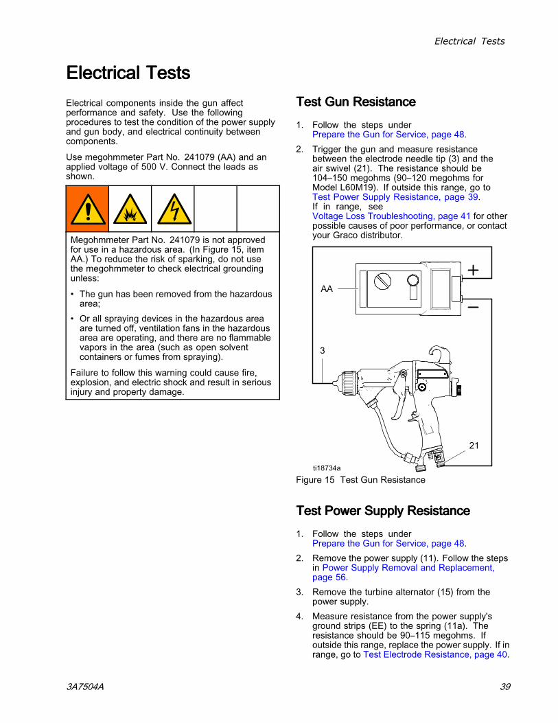
TestTestTest GunGunGun ResistanceResistanceResistance
1. Follow the steps underPrepare the Gun for Service, page 48.
2. Trigger the gun and measure resistancebetween the electrode needle tip (3) and theair swivel (21). The resistance should be104–150 megohms (90–120 megohms forModel L60M19). If outside this range, go toTest Power Supply Resistance, page 39.If in range, seeVoltage Loss Troubleshooting, page 41 for otherpossible causes of poor performance, or contactyour Graco distributor.
Figure 15 Test Gun Resistance
TestTestTest PowerPowerPower SupplySupplySupply ResistanceResistanceResistance
1. Follow the steps underPrepare the Gun for Service, page 48.
2. Remove the power supply (11). Follow the stepsin Power Supply Removal and Replacement,page 56.
3. Remove the turbine alternator (15) from thepower supply.
4. Measure resistance from the power supply'sground strips (EE) to the spring (11a). Theresistance should be 90–115 megohms. Ifoutside this range, replace the power supply. If inrange, go to Test Electrode Resistance, page 40.
3A7504A 39
Electrical Tests
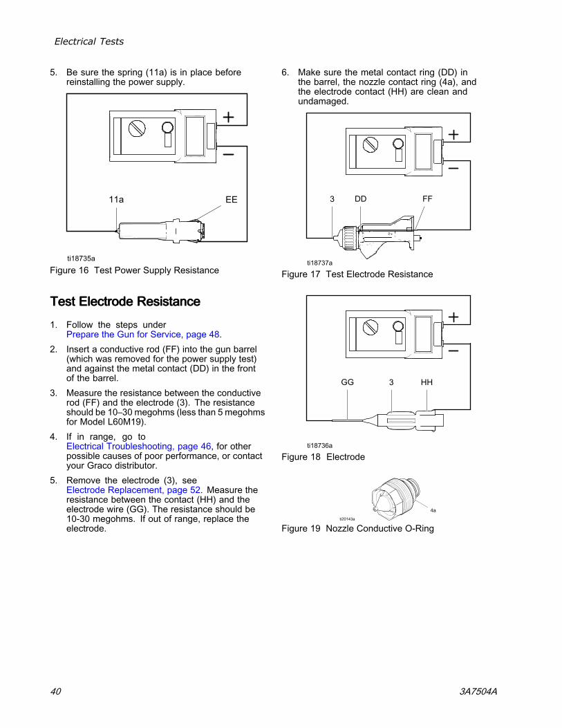
5. Be sure the spring (11a) is in place beforereinstalling the power supply.
Figure 16 Test Power Supply Resistance
TestTestTest ElectrodeElectrodeElectrode ResistanceResistanceResistance
1. Follow the steps underPrepare the Gun for Service, page 48.
2. Insert a conductive rod (FF) into the gun barrel(which was removed for the power supply test)and against the metal contact (DD) in the frontof the barrel.
3. Measure the resistance between the conductiverod (FF) and the electrode (3). The resistanceshould be 10–30 megohms (less than 5 megohmsfor Model L60M19).
4. If in range, go toElectrical Troubleshooting, page 46, for otherpossible causes of poor performance, or contactyour Graco distributor.
5. Remove the electrode (3), seeElectrode Replacement, page 52. Measure theresistance between the contact (HH) and theelectrode wire (GG). The resistance should be10-30 megohms. If out of range, replace theelectrode.
6. Make sure the metal contact ring (DD) inthe barrel, the nozzle contact ring (4a), andthe electrode contact (HH) are clean andundamaged.
Figure 17 Test Electrode Resistance
Figure 18 Electrode
Figure 19 Nozzle Conductive O-Ring
40 3A7504A
Troubleshooting
TroubleshootingTroubleshootingTroubleshooting
Installing and servicing this equipment requiresaccess to parts which may cause an electric shockor other serious injury if the work is not performedproperly. Do not install or repair this equipmentunless you are trained and qualified.
Follow the Fluid Voltage Discharge and GroundingProcedure, page 33 before checking or servicingthe system and whenever you are instructed todischarge the voltage.
To reduce the risk of an injury, follow thePressure Relief Procedure, page 33, wheneveryou are instructed to relieve the pressure.
Check all possible remedies in the TroubleshootingChart before disassembling the gun.
VoltageVoltageVoltage LossLossLoss TroubleshootingTroubleshootingTroubleshooting
Normal spraying voltage for a system using thewaterborne gun is 45-55 kV. The system voltage islower due to spraying current demands and voltageisolation system losses.
A loss of spraying voltage can be caused by aproblem with the spray gun, fluid hose, or voltageisolation system, since all of the system components
are electrically connected through the conductive,waterborne fluid.
Before troubleshooting or servicing the voltageisolation system itself, you need to determine whichcomponent in the system is most likely causing aproblem. Possible causes include the following:
SpraySpraySpray GunGunGun
• Fluid leakage• Dielectric breakdown at the fluid hose connectionor fluid packings
• Not enough air pressure for the alternator turbine• Faulty power supply• Excessive overspray on gun surfaces• Fluid in the air passages
WaterborneWaterborneWaterborne FluidFluidFluid HoseHoseHose
• Dielectric failure of the hose (pin-hole leak in thePTFE layer)
• Air gap in the fluid column between the gun and theisolated fluid supply, causing a low voltage readingon the isolation system voltage meter.
VoltageVoltageVoltage IsolationIsolationIsolation SystemSystemSystem
• Fluid leakage• Dirty interior
3A7504A 41
Troubleshooting
VisualVisualVisual ChecksChecksChecks
First, check the system for any visible faults or errorsto help isolate whether the spray gun, fluid hose orvoltage isolation system has failed. A voltage probeand meter, part no. 245277, is helpful for diagnosingvoltage problems and is required for some of thetroubleshooting tests that follow.
1. Check that all of the air and fluid tubes and hosesare properly connected.
2. Check that the voltage isolation system valvesand controls are properly set for operation.
3. Check that the interior of the isolated enclosureis clean.
4. Check that the spray gun and voltage isolationsystem have sufficient air pressure.
5. Check that the gun ES ON/OFF valve is in theON position and that the gun ES indicator lightis on. If the ES indicator light is not on, removethe spray gun for service and complete theElectrical Tests, page 39.
6. Check that the voltage isolation system'senclosure door is closed and that any safetyinterlocks are engaged and working properly.
7. Make sure the voltage isolation system is inthe “isolate” mode, where it is isolating the fluidvoltage from ground.
8. To eliminate air gaps in the fluid column, sprayenough fluid to purge the air out between thevoltage isolation system and the spray gun. Anair gap in the fluid hose can break the electricalcontinuity between the spray gun and the isolatedfluid supply and cause a low voltage reading ona voltage meter connected to the isolated fluidsupply.
9. Check the spray gun cover and barrel foraccumulated overspray. Excessive overspraycan create a conductive path back to thegrounded gun handle. Install a new gun coverand clean the exterior of the gun.
10. Inspect the entire system for any visible fluidleakage and repair any fluid leaks that are found.Pay special attention to the following areas:
• Packing area of the spray gun.• Fluid hose: check for leakage or any bulges inthe outer cover, which may indicate an internalleak.
• Internal voltage isolation system components
TestsTestsTests
If you still have no voltage, separate the spray gunand hose from the voltage isolation system andcheck whether the gun and hose alone will holdvoltage with the following test.
1. Flush the system with water and leave the linesfilled with water.
2. Discharge the system voltage (see Fluid VoltageDischarge and Grounding Procedure, page 33).
3. Follow the Pressure Relief Procedure, page 33.4. Disconnect the fluid hose from the voltage
isolation system.
Avoid allowing any water to leak out of the fluidhose as that could cause a significant air gap inthe fluid column up to the gun electrode, whichcan break the conductivity path and conceal apotential failure area.
5. Position the end of the hose as far as possibleaway from any grounded surface. The end ofthe hose must be at least 1 ft. (0.3 m) from anyground. Make sure that no one is within 3 ft. (0.9m) of the end of the hose.
6. Turn the ES ON/OFF valve to ON and triggerthe gun just enough to turn on the air to the gunbut not the fluid. Measure the voltage at the gunelectrode with a voltage probe and meter.
7. Discharge the system voltage by waiting 30seconds and then touching the gun electrodewith a grounded rod.
8. Check the meter reading:
• If the meter reading is 45 to 55 kV, the gun andfluid hose are okay, and the problem is in thevoltage isolation system.
• If the meter reading is below 45 kV, theproblem is in the gun or fluid hose.
9. Flush the fluid hose and gun with enough air todry out the fluid passages.
10. Turn the ES ON/OFF valve to ON and trigger thegun. Measure the voltage at the gun electrodewith a voltage probe and meter.
• If the meter reading is 45-55 kV, the gunpower supply is okay, and there is probably adielectric breakdown somewhere in the fluidhose or gun. Continue with step 11.
• If the meter reading is below 45 kV, do theElectrical Tests, page 39, to check the gun andpower supply resistance. If those tests showthe gun and power supply are okay, continuewith step 11.
42 3A7504A
Troubleshooting
11. A dielectric breakdown is most likely in one ofthe following three areas. Repair or replace thecomponent that is failing.
a. Fluid hose:
• Check for leakage or any bulges in theouter cover, which may indicate a pin-holeleak through the PTFE layer. Disconnectthe fluid hose from the gun, and look forsigns of fluid contamination on the outsideof the PTFE portion of the fluid tube.
• Inspect the end of the hose connected tothe voltage isolation system. Look for cutsor nicks.
• Make sure the hose is properly stripped(see Connect the Waterborne Fluid Hose,page 16). Restrip or replace the hose.
b. Fluid packings:
Remove the packing assembly from the gun(see Fluid Packing Rod Removal, page 53),and look for signs of fluid leakage or anyblackened areas, which would indicate arcingis occurring along the packing rod.
c. Fluid hose connection to the spray gun:
A breakdown at the fluid hose connectionjoint would be caused by fluid leaking pastthe o-ring seals on the end of the hose.Remove the hose at the gun connection andlook for signs of fluid leakage along the PTFEtube.
12. Before reassembling the gun, clean and dry thegun fluid inlet tube. Repack the inner spacer ofthe fluid packing rod with dielectric grease andreassemble the gun.
13. Reconnect the fluid hose.14. Check the gun voltage with the voltage probe
and meter before filling the gun with fluid.
3A7504A 43
Troubleshooting
SpraySpraySpray PatternPatternPattern TroubleshootingTroubleshootingTroubleshooting
Check all possible remedies in the TroubleshootingChart before disassembling the gun.
Some spray pattern problems are caused by theimproper balance between air and fluid.
ProblemProblemProblem CauseCauseCause SolutionSolutionSolution
No fluid. Refill supply.
Loose, dirty, damagednozzle/seat.
Clean or replace nozzle, seeClean the Gun Daily, page 36, orAir Cap and Nozzle Replacement,page 49.
Fluttering or spitting spray.
Air in fluid supply. Check fluid source. Refill.
Improper spray pattern. Damaged or dirty nozzle or air cap. Clean or replace. See Air Cap andNozzle Replacement, page 49.
Fluid buildup on air cap or nozzle. Clean. SeeClean the Gun Daily, page 36.
Fan air pressure too high. Decrease.
Fluid too thin. Increase viscosity.
Fluid pressure too low. Increase.
Fan air pressure too low. Increase.
Fluid too thick. Reduce viscosity.
Too much fluid. Decrease flow.
Did not apply 50% overlap. Overlap strokes 50%.Streaks.
Dirty or damaged air cap. Clean or replace air cap. SeeClean the Gun Daily, page 36, orAir Cap and Nozzle Replacement,page 49.
44 3A7504A
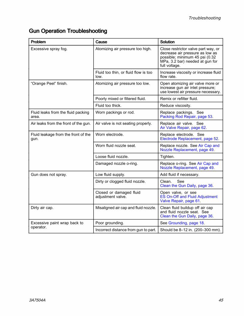
Troubleshooting
GunGunGun OperationOperationOperation TroubleshootingTroubleshootingTroubleshooting
ProblemProblemProblem CauseCauseCause SolutionSolutionSolution
Atomizing air pressure too high. Close restrictor valve part way, ordecrease air pressure as low aspossible; minimum 45 psi (0.32MPa, 3.2 bar) needed at gun forfull voltage.
Excessive spray fog.
Fluid too thin, or fluid flow is toolow.
Increase viscosity or increase fluidflow rate.
Atomizing air pressure too low. Open atomizing air valve more orincrease gun air inlet pressure;use lowest air pressure necessary.
Poorly mixed or filtered fluid. Remix or refilter fluid.
“Orange Peel” finish.
Fluid too thick. Reduce viscosity.
Fluid leaks from the fluid packingarea.
Worn packings or rod. Replace packings. SeePacking Rod Repair, page 53.
Air leaks from the front of the gun. Air valve is not seating properly. Replace air valve. SeeAir Valve Repair, page 62.
Worn electrode. Replace electrode. SeeElectrode Replacement, page 52.
Worn fluid nozzle seat. Replace nozzle. See Air Cap andNozzle Replacement, page 49.
Loose fluid nozzle. Tighten.
Fluid leakage from the front of thegun.
Damaged nozzle o-ring. Replace o-ring. See Air Cap andNozzle Replacement, page 49.
Low fluid supply. Add fluid if necessary.
Dirty or clogged fluid nozzle. Clean. SeeClean the Gun Daily, page 36.
Gun does not spray.
Closed or damaged fluidadjustment valve.
Open valve, or seeES On-Off and Fluid AdjustmentValve Repair, page 61.
Dirty air cap. Misaligned air cap and fluid nozzle. Clean fluid buildup off air capand fluid nozzle seat. SeeClean the Gun Daily, page 36.
Poor grounding. See Grounding, page 18.Excessive paint wrap back tooperator.
Incorrect distance from gun to part. Should be 8–12 in. (200–300 mm).
3A7504A 45
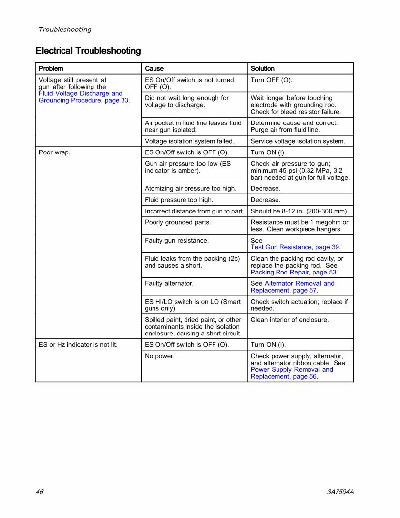
Troubleshooting
ElectricalElectricalElectrical TroubleshootingTroubleshootingTroubleshooting
ProblemProblemProblem CauseCauseCause SolutionSolutionSolution
ES On/Off switch is not turnedOFF (O).
Turn OFF (O).
Did not wait long enough forvoltage to discharge.
Wait longer before touchingelectrode with grounding rod.Check for bleed resistor failure.
Air pocket in fluid line leaves fluidnear gun isolated.
Determine cause and correct.Purge air from fluid line.
Voltage still present atgun after following theFluid Voltage Discharge andGrounding Procedure, page 33.
Voltage isolation system failed. Service voltage isolation system.
ES On/Off switch is OFF (O). Turn ON (I).
Gun air pressure too low (ESindicator is amber).
Check air pressure to gun;minimum 45 psi (0.32 MPa, 3.2bar) needed at gun for full voltage.
Atomizing air pressure too high. Decrease.
Fluid pressure too high. Decrease.
Incorrect distance from gun to part. Should be 8-12 in. (200-300 mm).
Poorly grounded parts. Resistance must be 1 megohm orless. Clean workpiece hangers.
Faulty gun resistance. SeeTest Gun Resistance, page 39.
Fluid leaks from the packing (2c)and causes a short.
Clean the packing rod cavity, orreplace the packing rod. SeePacking Rod Repair, page 53.
Faulty alternator. See Alternator Removal andReplacement, page 57.
ES HI/LO switch is on LO (Smartguns only)
Check switch actuation; replace ifneeded.
Poor wrap.
Spilled paint, dried paint, or othercontaminants inside the isolationenclosure, causing a short circuit.
Clean interior of enclosure.
ES On/Off switch is OFF (O). Turn ON (I).ES or Hz indicator is not lit.
No power. Check power supply, alternator,and alternator ribbon cable. SeePower Supply Removal andReplacement, page 56.
46 3A7504A
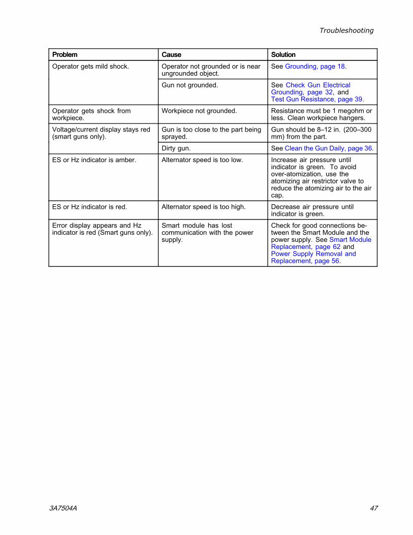
Troubleshooting
ProblemProblemProblem CauseCauseCause SolutionSolutionSolution
Operator not grounded or is nearungrounded object.
See Grounding, page 18.Operator gets mild shock.
Gun not grounded. See Check Gun ElectricalGrounding, page 32, andTest Gun Resistance, page 39.
Operator gets shock fromworkpiece.
Workpiece not grounded. Resistance must be 1 megohm orless. Clean workpiece hangers.
Gun is too close to the part beingsprayed.
Gun should be 8–12 in. (200–300mm) from the part.
Voltage/current display stays red(smart guns only).
Dirty gun. See Clean the Gun Daily, page 36.
ES or Hz indicator is amber. Alternator speed is too low. Increase air pressure untilindicator is green. To avoidover-atomization, use theatomizing air restrictor valve toreduce the atomizing air to the aircap.
ES or Hz indicator is red. Alternator speed is too high. Decrease air pressure untilindicator is green.
Error display appears and Hzindicator is red (Smart guns only).
Smart module has lostcommunication with the powersupply.
Check for good connections be-tween the Smart Module and thepower supply. See Smart ModuleReplacement, page 62 andPower Supply Removal andReplacement, page 56.
3A7504A 47
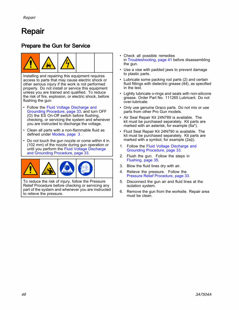
Repair
RepairRepairRepair
PreparePreparePrepare thethethe GunGunGun forforfor ServiceServiceService
Installing and repairing this equipment requiresaccess to parts that may cause electric shock orother serious injury if the work is not performedproperly. Do not install or service this equipmentunless you are trained and qualified. To reducethe risk of fire, explosion, or electric shock, beforeflushing the gun:
• Follow the Fluid Voltage Discharge andGrounding Procedure, page 33, and turn OFF(O) the ES On-Off switch before flushing,checking, or servicing the system and wheneveryou are instructed to discharge the voltage.
• Clean all parts with a non-flammable fluid asdefined under Models, page 3 .
• Do not touch the gun nozzle or come within 4 in.(102 mm) of the nozzle during gun operation oruntil you perform the Fluid Voltage Dischargeand Grounding Procedure, page 33.
To reduce the risk of injury, follow the PressureRelief Procedure before checking or servicing anypart of the system and whenever you are instructedto relieve the pressure.
• Check all possible remediesin Troubleshooting, page 41 before disassemblingthe gun.
• Use a vise with padded jaws to prevent damageto plastic parts.
• Lubricate some packing rod parts (2) and certainfluid fittings with dielectric grease (44), as specifiedin the text.
• Lightly lubricate o-rings and seals with non-siliconegrease. Order Part No. 111265 Lubricant. Do notover-lubricate.
• Only use genuine Graco parts. Do not mix or useparts from other Pro Gun models.
• Air Seal Repair Kit 24N789 is available. Thekit must be purchased separately. Kit parts aremarked with an asterisk, for example (6a*).
• Fluid Seal Repair Kit 24N790 is available. Thekit must be purchased separately. Kit parts aremarked with a symbol, for example (2a‡).
1. Follow the Fluid Voltage Discharge andGrounding Procedure, page 33.
2. Flush the gun. Follow the steps inFlushing, page 35.
3. Blow the fluid lines dry with air.4. Relieve the pressure. Follow the
Pressure Relief Procedure, page 33.5. Disconnect the gun air and fluid lines at the
isolation system.6. Remove the gun from the worksite. Repair area
must be clean.
48 3A7504A
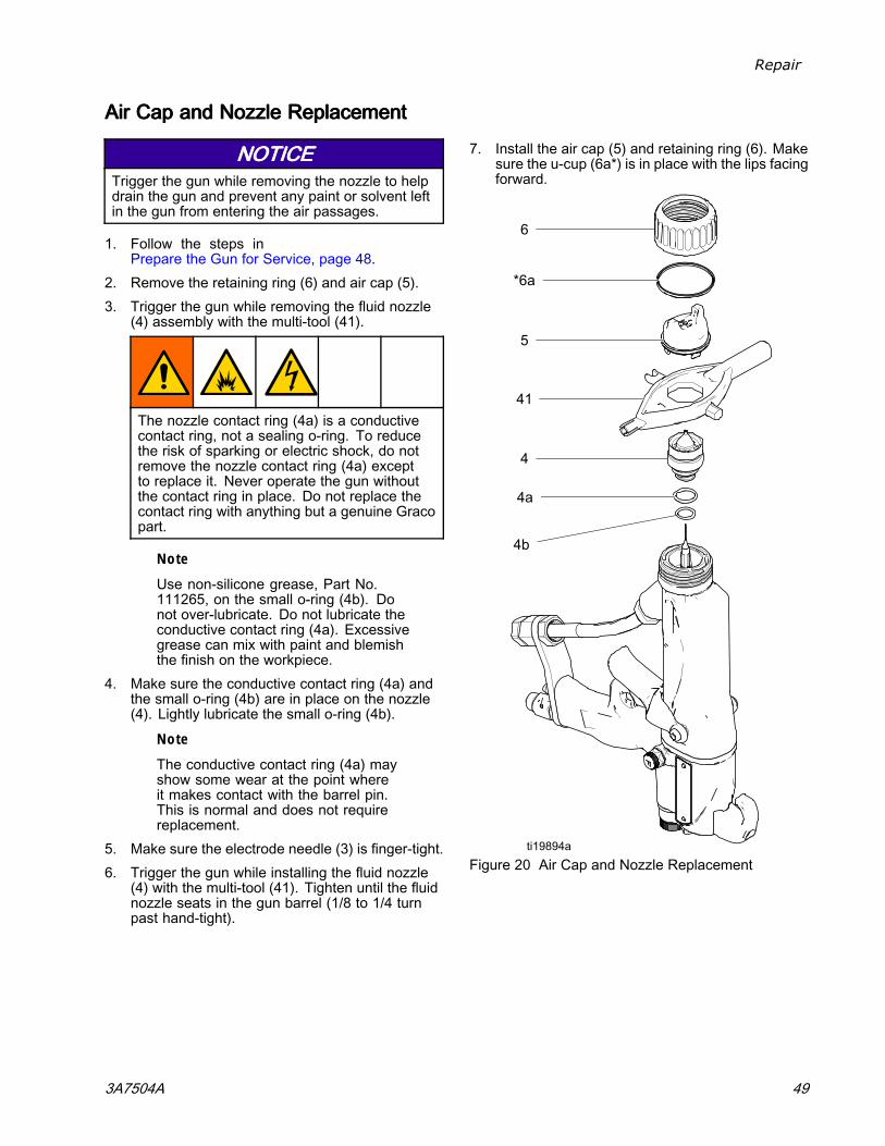
Repair
AirAirAir CapCapCap andandand NozzleNozzleNozzle ReplacementReplacementReplacement
NOTICENOTICENOTICETrigger the gun while removing the nozzle to helpdrain the gun and prevent any paint or solvent leftin the gun from entering the air passages.
1. Follow the steps inPrepare the Gun for Service, page 48.
2. Remove the retaining ring (6) and air cap (5).3. Trigger the gun while removing the fluid nozzle
(4) assembly with the multi-tool (41).
The nozzle contact ring (4a) is a conductivecontact ring, not a sealing o-ring. To reducethe risk of sparking or electric shock, do notremove the nozzle contact ring (4a) exceptto replace it. Never operate the gun withoutthe contact ring in place. Do not replace thecontact ring with anything but a genuine Gracopart.
Note
Use non-silicone grease, Part No.111265, on the small o-ring (4b). Donot over-lubricate. Do not lubricate theconductive contact ring (4a). Excessivegrease can mix with paint and blemishthe finish on the workpiece.
4. Make sure the conductive contact ring (4a) andthe small o-ring (4b) are in place on the nozzle(4). Lightly lubricate the small o-ring (4b).
Note
The conductive contact ring (4a) mayshow some wear at the point whereit makes contact with the barrel pin.This is normal and does not requirereplacement.
5. Make sure the electrode needle (3) is finger-tight.6. Trigger the gun while installing the fluid nozzle
(4) with the multi-tool (41). Tighten until the fluidnozzle seats in the gun barrel (1/8 to 1/4 turnpast hand-tight).
7. Install the air cap (5) and retaining ring (6). Makesure the u-cup (6a*) is in place with the lips facingforward.
Figure 20 Air Cap and Nozzle Replacement
3A7504A 49
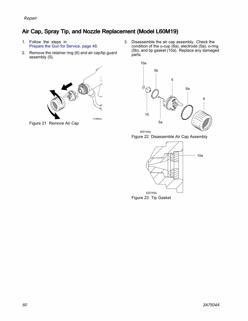
Repair
AirAirAir Cap,Cap,Cap, SpraySpraySpray Tip,Tip,Tip, andandand NozzleNozzleNozzle ReplacementReplacementReplacement (Model(Model(Model L60M19)L60M19)L60M19)
1. Follow the steps inPrepare the Gun for Service, page 48.
2. Remove the retainer ring (6) and air cap/tip guardassembly (5).
Figure 21 Remove Air Cap
3. Disassemble the air cap assembly. Check thecondition of the u-cup (6a), electrode (5a), o-ring(5b), and tip gasket (10a). Replace any damagedparts.
Figure 22 Disassemble Air Cap Assembly
Figure 23 Tip Gasket
50 3A7504A
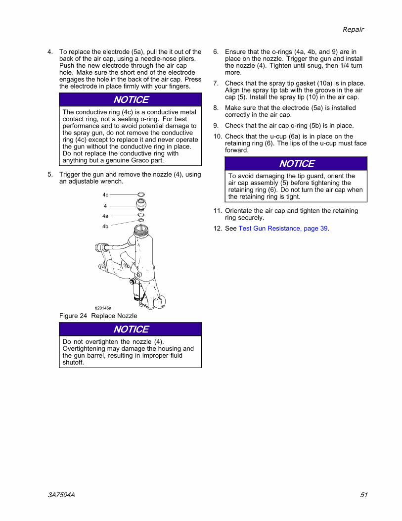
Repair
4. To replace the electrode (5a), pull the it out of theback of the air cap, using a needle-nose pliers.Push the new electrode through the air caphole. Make sure the short end of the electrodeengages the hole in the back of the air cap. Pressthe electrode in place firmly with your fingers.
NOTICENOTICENOTICEThe conductive ring (4c) is a conductive metalcontact ring, not a sealing o-ring. For bestperformance and to avoid potential damage tothe spray gun, do not remove the conductivering (4c) except to replace it and never operatethe gun without the conductive ring in place.Do not replace the conductive ring withanything but a genuine Graco part.
5. Trigger the gun and remove the nozzle (4), usingan adjustable wrench.
Figure 24 Replace Nozzle
NOTICENOTICENOTICEDo not overtighten the nozzle (4).Overtightening may damage the housing andthe gun barrel, resulting in improper fluidshutoff.
6. Ensure that the o-rings (4a, 4b, and 9) are inplace on the nozzle. Trigger the gun and installthe nozzle (4). Tighten until snug, then 1/4 turnmore.
7. Check that the spray tip gasket (10a) is in place.Align the spray tip tab with the groove in the aircap (5). Install the spray tip (10) in the air cap.
8. Make sure that the electrode (5a) is installedcorrectly in the air cap.
9. Check that the air cap o-ring (5b) is in place.10. Check that the u-cup (6a) is in place on the
retaining ring (6). The lips of the u-cup must faceforward.
NOTICENOTICENOTICETo avoid damaging the tip guard, orient theair cap assembly (5) before tightening theretaining ring (6). Do not turn the air cap whenthe retaining ring is tight.
11. Orientate the air cap and tighten the retainingring securely.
12. See Test Gun Resistance, page 39.
3A7504A 51
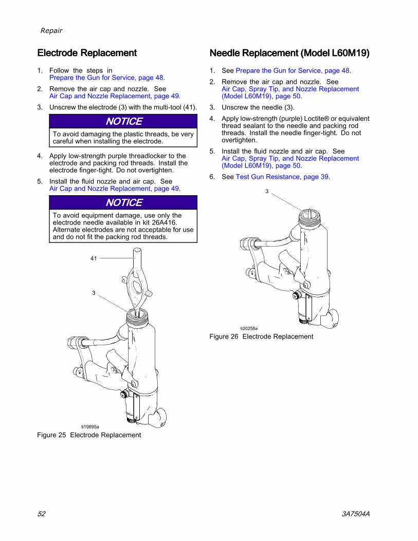
Repair
ElectrodeElectrodeElectrode ReplacementReplacementReplacement
1. Follow the steps inPrepare the Gun for Service, page 48.
2. Remove the air cap and nozzle. SeeAir Cap and Nozzle Replacement, page 49.
3. Unscrew the electrode (3) with the multi-tool (41).
NOTICENOTICENOTICETo avoid damaging the plastic threads, be verycareful when installing the electrode.
4. Apply low-strength purple threadlocker to theelectrode and packing rod threads. Install theelectrode finger-tight. Do not overtighten.
5. Install the fluid nozzle and air cap. SeeAir Cap and Nozzle Replacement, page 49.
NOTICENOTICENOTICETo avoid equipment damage, use only theelectrode needle available in kit 26A416.Alternate electrodes are not acceptable for useand do not fit the packing rod threads.
Figure 25 Electrode Replacement
NeedleNeedleNeedle ReplacementReplacementReplacement (Model(Model(Model L60M19)L60M19)L60M19)
1. See Prepare the Gun for Service, page 48.2. Remove the air cap and nozzle. See
Air Cap, Spray Tip, and Nozzle Replacement(Model L60M19), page 50.
3. Unscrew the needle (3).4. Apply low-strength (purple) Loctite® or equivalent
thread sealant to the needle and packing rodthreads. Install the needle finger-tight. Do notovertighten.
5. Install the fluid nozzle and air cap. SeeAir Cap, Spray Tip, and Nozzle Replacement(Model L60M19), page 50.
6. See Test Gun Resistance, page 39.
Figure 26 Electrode Replacement
52 3A7504A
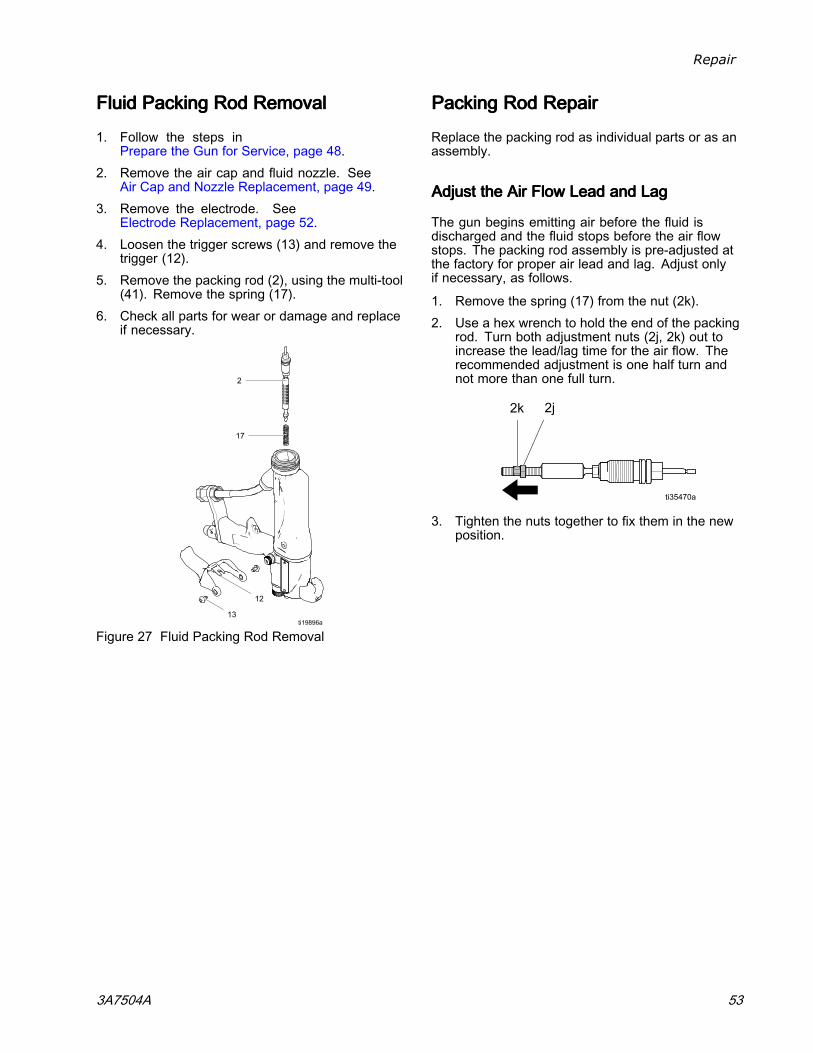
Repair
FluidFluidFluid PackingPackingPacking RodRodRod RemovalRemovalRemoval
1. Follow the steps inPrepare the Gun for Service, page 48.
2. Remove the air cap and fluid nozzle. SeeAir Cap and Nozzle Replacement, page 49.
3. Remove the electrode. SeeElectrode Replacement, page 52.
4. Loosen the trigger screws (13) and remove thetrigger (12).
5. Remove the packing rod (2), using the multi-tool(41). Remove the spring (17).
6. Check all parts for wear or damage and replaceif necessary.
Figure 27 Fluid Packing Rod Removal
PackingPackingPacking RodRodRod RepairRepairRepair
Replace the packing rod as individual parts or as anassembly.
AdjustAdjustAdjust thethethe AirAirAir FlowFlowFlow LeadLeadLead andandand LagLagLag
The gun begins emitting air before the fluid isdischarged and the fluid stops before the air flowstops. The packing rod assembly is pre-adjusted atthe factory for proper air lead and lag. Adjust onlyif necessary, as follows.
1. Remove the spring (17) from the nut (2k).2. Use a hex wrench to hold the end of the packing
rod. Turn both adjustment nuts (2j, 2k) out toincrease the lead/lag time for the air flow. Therecommended adjustment is one half turn andnot more than one full turn.
3. Tighten the nuts together to fix them in the newposition.
3A7504A 53
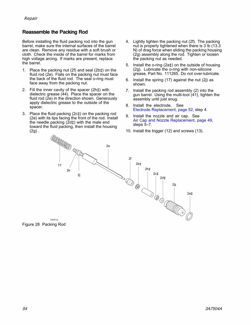
Repair
ReassembleReassembleReassemble thethethe PackingPackingPacking RodRodRod
Before installing the fluid packing rod into the gunbarrel, make sure the internal surfaces of the barrelare clean. Remove any residue with a soft brush orcloth. Check the inside of the barrel for marks fromhigh voltage arcing. If marks are present, replacethe barrel.
1. Place the packing nut (2f) and seal (2b‡) on thefluid rod (2e). Flats on the packing nut must facethe back of the fluid rod. The seal o-ring mustface away from the packing nut.
2. Fill the inner cavity of the spacer (2h‡) withdielectric grease (44). Place the spacer on thefluid rod (2e) in the direction shown. Generouslyapply dielectric grease to the outside of thespacer.
3. Place the fluid packing (2c‡) on the packing rod(2e) with its lips facing the front of the rod. Installthe needle packing (2d‡) with the male endtoward the fluid packing, then install the housing(2g) .
4. Lightly tighten the packing nut (2f). The packingnut is properly tightened when there is 3 lb (13.3N) of drag force when sliding the packing housing(2g) assembly along the rod. Tighten or loosenthe packing nut as needed.
5. Install the o-ring (2a‡) on the outside of housing(2g). Lubricate the o-ring with non-siliconegrease, Part No. 111265. Do not over-lubricate.
6. Install the spring (17) against the nut (2j) asshown.
7. Install the packing rod assembly (2) into thegun barrel. Using the multi-tool (41), tighten theassembly until just snug.
8. Install the electrode. SeeElectrode Replacement, page 52, step 4.
9. Install the nozzle and air cap. SeeAir Cap and Nozzle Replacement, page 49,steps 5–7.
10. Install the trigger (12) and screws (13).
Figure 28 Packing Rod
54 3A7504A
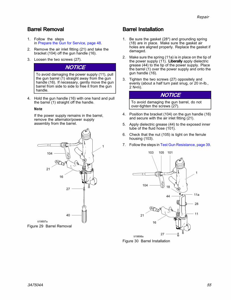
Repair
BarrelBarrelBarrel RemovalRemovalRemoval
1. Follow the stepsin Prepare the Gun for Service, page 48.
2. Remove the air inlet fitting (21) and take thebracket (104) off the gun handle (16).
3. Loosen the two screws (27).
NOTICENOTICENOTICETo avoid damaging the power supply (11), pullthe gun barrel (1) straight away from the gunhandle (16). If necessary, gently move the gunbarrel from side to side to free it from the gunhandle.
4. Hold the gun handle (16) with one hand and pullthe barrel (1) straight off the handle.
Note
If the power supply remains in the barrel,remove the alternator/power supplyassembly from the barrel.
Figure 29 Barrel Removal
BarrelBarrelBarrel InstallationInstallationInstallation
1. Be sure the gasket (28*) and grounding spring(18) are in place. Make sure the gasket airholes are aligned properly. Replace the gasket ifdamaged.
2. Make sure the spring (11a) is in place on the tip ofthe power supply (11). LiberallyLiberallyLiberally apply dielectricgrease (44) to the tip of the power supply. Placethe barrel (1) over the power supply and onto thegun handle (16).
3. Tighten the two screws (27) oppositely andevenly (about a half turn past snug, or 20 in-lb.,2 N•m).
NOTICENOTICENOTICETo avoid damaging the gun barrel, do notover-tighten the screws (27).
4. Position the bracket (104) on the gun handle (16)and secure with the air inlet fitting (21).
5. Apply dielectric grease (44) to the exposed innertube of the fluid hose (101).
6. Check that the nut (105) is tight on the ferrulehousing (103).
7. Follow the steps in Test Gun Resistance, page 39.
Figure 30 Barrel Installation
3A7504A 55
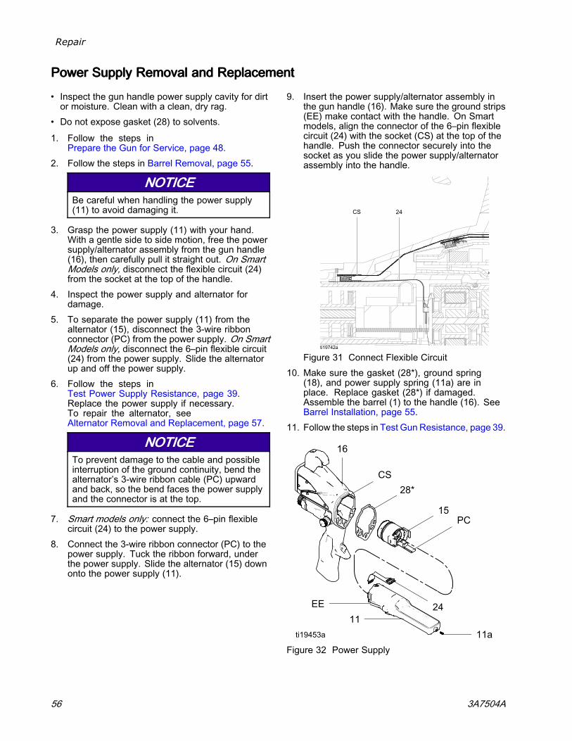
Repair
PowerPowerPower SupplySupplySupply RemovalRemovalRemoval andandand ReplacementReplacementReplacement
• Inspect the gun handle power supply cavity for dirtor moisture. Clean with a clean, dry rag.
• Do not expose gasket (28) to solvents.
1. Follow the steps inPrepare the Gun for Service, page 48.
2. Follow the steps in Barrel Removal, page 55.
NOTICENOTICENOTICEBe careful when handling the power supply(11) to avoid damaging it.
3. Grasp the power supply (11) with your hand.With a gentle side to side motion, free the powersupply/alternator assembly from the gun handle(16), then carefully pull it straight out. On SmartModels only, disconnect the flexible circuit (24)from the socket at the top of the handle.
4. Inspect the power supply and alternator fordamage.
5. To separate the power supply (11) from thealternator (15), disconnect the 3-wire ribbonconnector (PC) from the power supply. On SmartModels only, disconnect the 6–pin flexible circuit(24) from the power supply. Slide the alternatorup and off the power supply.
6. Follow the steps inTest Power Supply Resistance, page 39.Replace the power supply if necessary.To repair the alternator, seeAlternator Removal and Replacement, page 57.
NOTICENOTICENOTICETo prevent damage to the cable and possibleinterruption of the ground continuity, bend thealternator’s 3-wire ribbon cable (PC) upwardand back, so the bend faces the power supplyand the connector is at the top.
7. Smart models only: connect the 6–pin flexiblecircuit (24) to the power supply.
8. Connect the 3-wire ribbon connector (PC) to thepower supply. Tuck the ribbon forward, underthe power supply. Slide the alternator (15) downonto the power supply (11).
9. Insert the power supply/alternator assembly inthe gun handle (16). Make sure the ground strips(EE) make contact with the handle. On Smartmodels, align the connector of the 6–pin flexiblecircuit (24) with the socket (CS) at the top of thehandle. Push the connector securely into thesocket as you slide the power supply/alternatorassembly into the handle.
Figure 31 Connect Flexible Circuit10. Make sure the gasket (28*), ground spring
(18), and power supply spring (11a) are inplace. Replace gasket (28*) if damaged.Assemble the barrel (1) to the handle (16). SeeBarrel Installation, page 55.
11. Follow the steps in Test Gun Resistance, page 39.
Figure 32 Power Supply
56 3A7504A
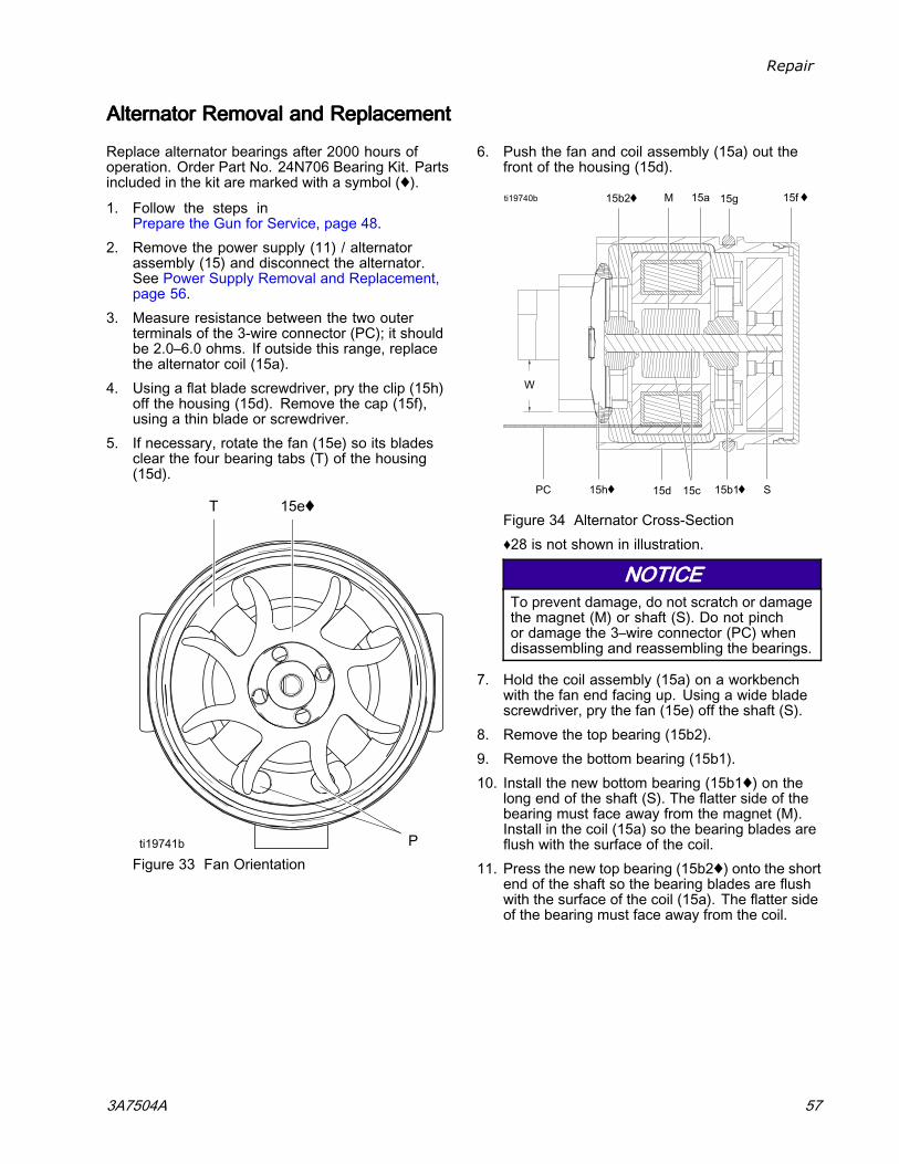
Repair
AlternatorAlternatorAlternator RemovalRemovalRemoval andandand ReplacementReplacementReplacement
Replace alternator bearings after 2000 hours ofoperation. Order Part No. 24N706 Bearing Kit. Partsincluded in the kit are marked with a symbol (♦).
1. Follow the steps inPrepare the Gun for Service, page 48.
2. Remove the power supply (11) / alternatorassembly (15) and disconnect the alternator.See Power Supply Removal and Replacement,page 56.
3. Measure resistance between the two outerterminals of the 3-wire connector (PC); it shouldbe 2.0–6.0 ohms. If outside this range, replacethe alternator coil (15a).
4. Using a flat blade screwdriver, pry the clip (15h)off the housing (15d). Remove the cap (15f),using a thin blade or screwdriver.
5. If necessary, rotate the fan (15e) so its bladesclear the four bearing tabs (T) of the housing(15d).
Figure 33 Fan Orientation
6. Push the fan and coil assembly (15a) out thefront of the housing (15d).
Figure 34 Alternator Cross-Section♦28 is not shown in illustration.
NOTICENOTICENOTICETo prevent damage, do not scratch or damagethe magnet (M) or shaft (S). Do not pinchor damage the 3–wire connector (PC) whendisassembling and reassembling the bearings.
7. Hold the coil assembly (15a) on a workbenchwith the fan end facing up. Using a wide bladescrewdriver, pry the fan (15e) off the shaft (S).
8. Remove the top bearing (15b2).9. Remove the bottom bearing (15b1).10. Install the new bottom bearing (15b1♦) on the
long end of the shaft (S). The flatter side of thebearing must face away from the magnet (M).Install in the coil (15a) so the bearing blades areflush with the surface of the coil.
11. Press the new top bearing (15b2♦) onto the shortend of the shaft so the bearing blades are flushwith the surface of the coil (15a). The flatter sideof the bearing must face away from the coil.
3A7504A 57
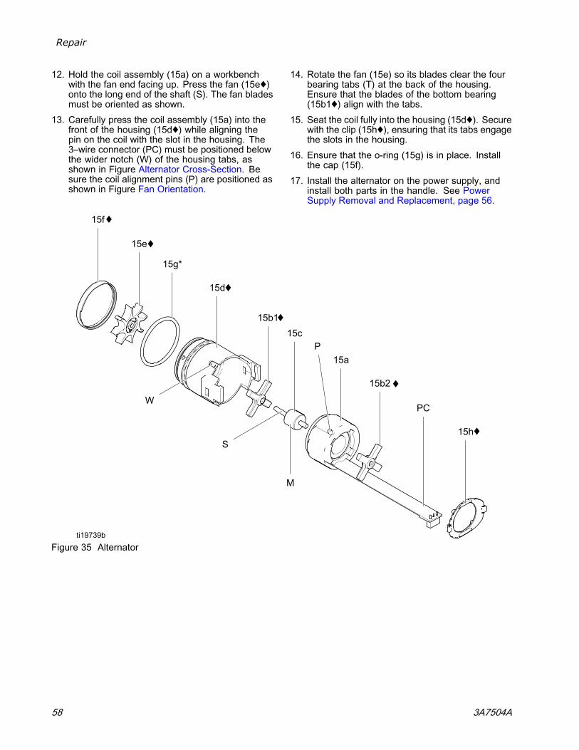
Repair
12. Hold the coil assembly (15a) on a workbenchwith the fan end facing up. Press the fan (15e♦)onto the long end of the shaft (S). The fan bladesmust be oriented as shown.
13. Carefully press the coil assembly (15a) into thefront of the housing (15d♦) while aligning thepin on the coil with the slot in the housing. The3–wire connector (PC) must be positioned belowthe wider notch (W) of the housing tabs, asshown in Figure Alternator Cross-Section. Besure the coil alignment pins (P) are positioned asshown in Figure Fan Orientation.
14. Rotate the fan (15e) so its blades clear the fourbearing tabs (T) at the back of the housing.Ensure that the blades of the bottom bearing(15b1♦) align with the tabs.
15. Seat the coil fully into the housing (15d♦). Securewith the clip (15h♦), ensuring that its tabs engagethe slots in the housing.
16. Ensure that the o-ring (15g) is in place. Installthe cap (15f).
17. Install the alternator on the power supply, andinstall both parts in the handle. See PowerSupply Removal and Replacement, page 56.
Figure 35 Alternator
58 3A7504A
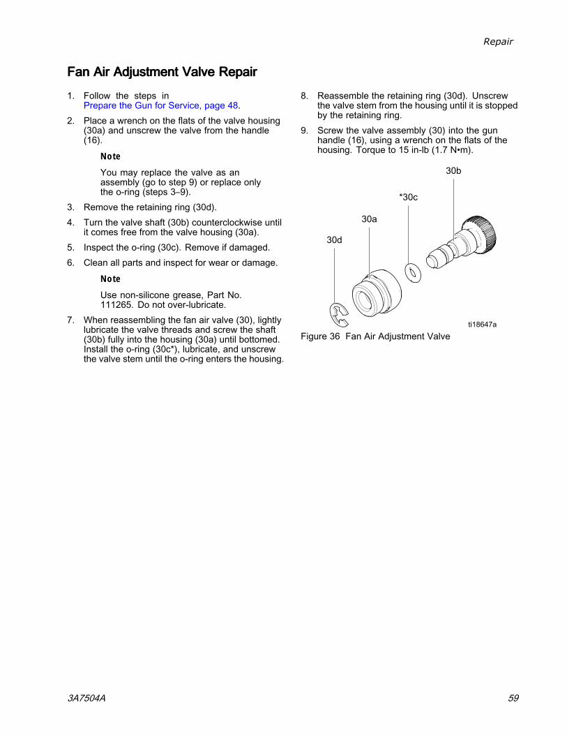
Repair
FanFanFan AirAirAir AdjustmentAdjustmentAdjustment ValveValveValve RepairRepairRepair
1. Follow the steps inPrepare the Gun for Service, page 48.
2. Place a wrench on the flats of the valve housing(30a) and unscrew the valve from the handle(16).
Note
You may replace the valve as anassembly (go to step 9) or replace onlythe o-ring (steps 3–9).
3. Remove the retaining ring (30d).4. Turn the valve shaft (30b) counterclockwise until
it comes free from the valve housing (30a).5. Inspect the o-ring (30c). Remove if damaged.6. Clean all parts and inspect for wear or damage.
Note
Use non-silicone grease, Part No.111265. Do not over-lubricate.
7. When reassembling the fan air valve (30), lightlylubricate the valve threads and screw the shaft(30b) fully into the housing (30a) until bottomed.Install the o-ring (30c*), lubricate, and unscrewthe valve stem until the o-ring enters the housing.
8. Reassemble the retaining ring (30d). Unscrewthe valve stem from the housing until it is stoppedby the retaining ring.
9. Screw the valve assembly (30) into the gunhandle (16), using a wrench on the flats of thehousing. Torque to 15 in-lb (1.7 N•m).
Figure 36 Fan Air Adjustment Valve
3A7504A 59
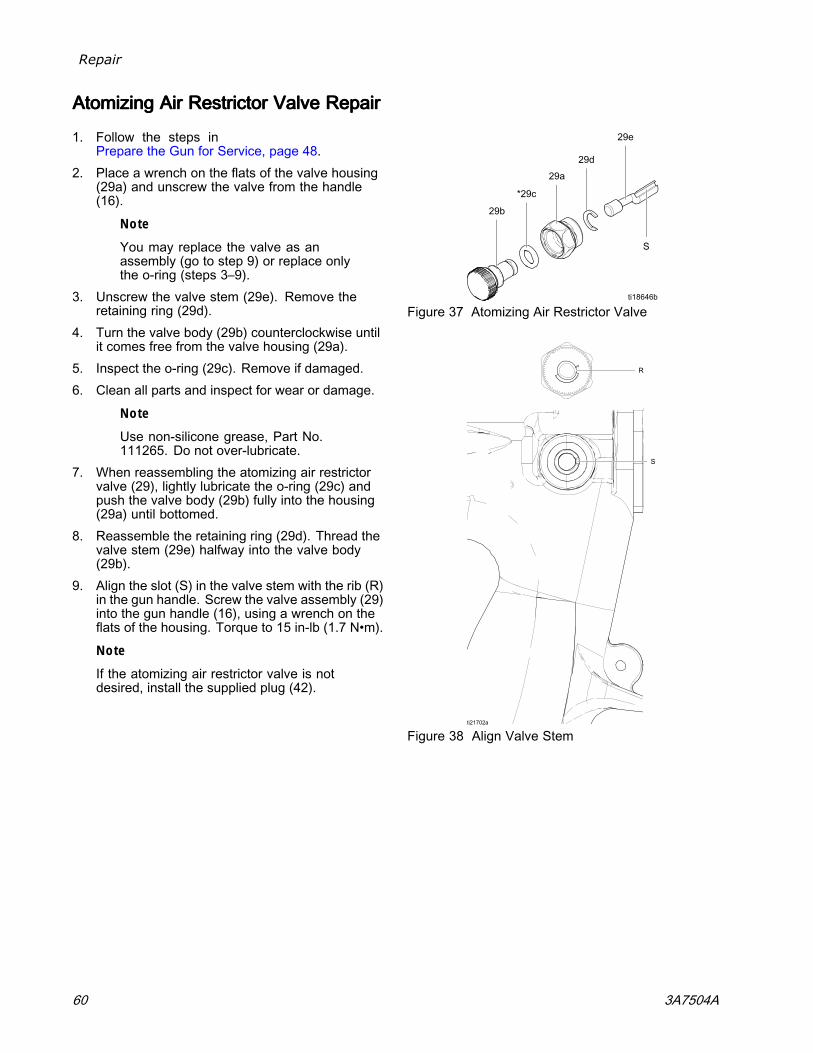
Repair
AtomizingAtomizingAtomizing AirAirAir RestrictorRestrictorRestrictor ValveValveValve RepairRepairRepair
1. Follow the steps inPrepare the Gun for Service, page 48.
2. Place a wrench on the flats of the valve housing(29a) and unscrew the valve from the handle(16).
Note
You may replace the valve as anassembly (go to step 9) or replace onlythe o-ring (steps 3–9).
3. Unscrew the valve stem (29e). Remove theretaining ring (29d).
4. Turn the valve body (29b) counterclockwise untilit comes free from the valve housing (29a).
5. Inspect the o-ring (29c). Remove if damaged.6. Clean all parts and inspect for wear or damage.
Note
Use non-silicone grease, Part No.111265. Do not over-lubricate.
7. When reassembling the atomizing air restrictorvalve (29), lightly lubricate the o-ring (29c) andpush the valve body (29b) fully into the housing(29a) until bottomed.
8. Reassemble the retaining ring (29d). Thread thevalve stem (29e) halfway into the valve body(29b).
9. Align the slot (S) in the valve stem with the rib (R)in the gun handle. Screw the valve assembly (29)into the gun handle (16), using a wrench on theflats of the housing. Torque to 15 in-lb (1.7 N•m).
Note
If the atomizing air restrictor valve is notdesired, install the supplied plug (42).
Figure 37 Atomizing Air Restrictor Valve
Figure 38 Align Valve Stem
60 3A7504A

Repair
ESESES OnOnOn---OffOffOff andandand FluidFluidFluid AdjustmentAdjustmentAdjustment ValveValveValve RepairRepairRepair1. Follow the steps in
Prepare the Gun for Service, page 48.2. Loosen the captive screw (26p). Remove the
valve (26) from the handle.3. Lubricate the o-rings (26b* and 26m*) with
non-silicone grease, Part No. 111265. Do notover-lubricate.
NoteDo not over-lubricate parts. Excessivelubricant on the o-rings can be pushedinto the gun air passage and blemish thefinish on the workpiece.
4. Clean and inspect parts for damage. Replaceif necessary.
Note
The protrusion on the retainer plate (26h)must point upward.
5. Reinstall the valve. Torque the screw (27) to15-25 in-lb (1.7-2.8 N•m).
Figure 39 ES On-Off Valve Repair, 24N630 and26A160
Figure 40 ES On-Off Valve Repair, 24N632
3A7504A 61
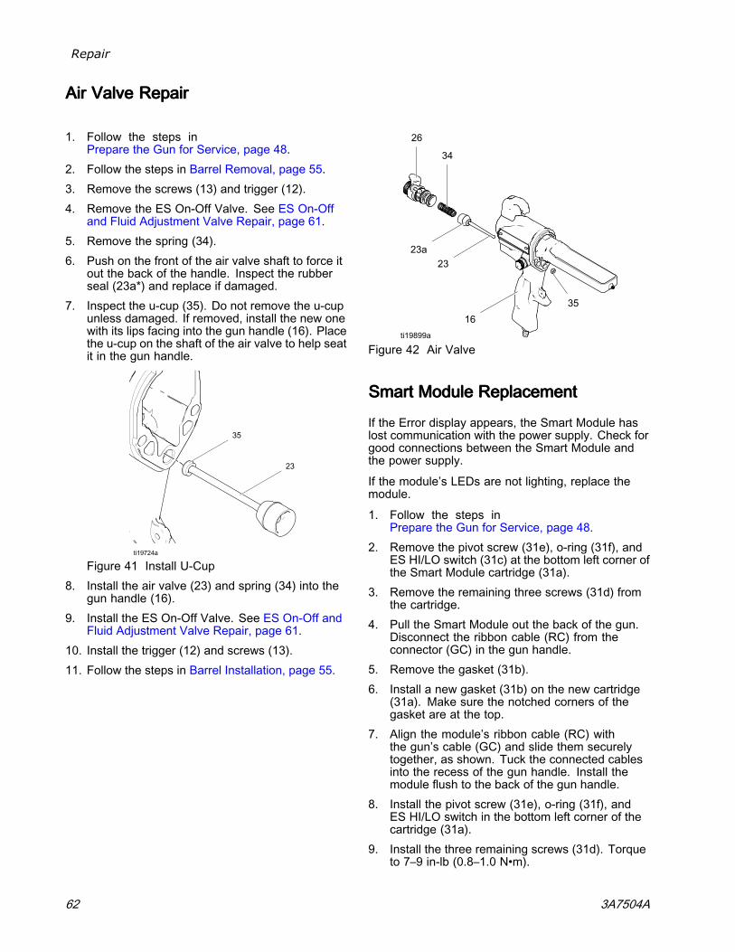
Repair
AirAirAir ValveValveValve RepairRepairRepair
1. Follow the steps inPrepare the Gun for Service, page 48.
2. Follow the steps in Barrel Removal, page 55.3. Remove the screws (13) and trigger (12).4. Remove the ES On-Off Valve. See ES On-Off
and Fluid Adjustment Valve Repair, page 61.5. Remove the spring (34).6. Push on the front of the air valve shaft to force it
out the back of the handle. Inspect the rubberseal (23a*) and replace if damaged.
7. Inspect the u-cup (35). Do not remove the u-cupunless damaged. If removed, install the new onewith its lips facing into the gun handle (16). Placethe u-cup on the shaft of the air valve to help seatit in the gun handle.
Figure 41 Install U-Cup8. Install the air valve (23) and spring (34) into the
gun handle (16).9. Install the ES On-Off Valve. See ES On-Off and
Fluid Adjustment Valve Repair, page 61.10. Install the trigger (12) and screws (13).11. Follow the steps in Barrel Installation, page 55.
Figure 42 Air Valve
SmartSmartSmart ModuleModuleModule ReplacementReplacementReplacement
If the Error display appears, the Smart Module haslost communication with the power supply. Check forgood connections between the Smart Module andthe power supply.
If the module’s LEDs are not lighting, replace themodule.
1. Follow the steps inPrepare the Gun for Service, page 48.
2. Remove the pivot screw (31e), o-ring (31f), andES HI/LO switch (31c) at the bottom left corner ofthe Smart Module cartridge (31a).
3. Remove the remaining three screws (31d) fromthe cartridge.
4. Pull the Smart Module out the back of the gun.Disconnect the ribbon cable (RC) from theconnector (GC) in the gun handle.
5. Remove the gasket (31b).6. Install a new gasket (31b) on the new cartridge
(31a). Make sure the notched corners of thegasket are at the top.
7. Align the module’s ribbon cable (RC) withthe gun’s cable (GC) and slide them securelytogether, as shown. Tuck the connected cablesinto the recess of the gun handle. Install themodule flush to the back of the gun handle.
8. Install the pivot screw (31e), o-ring (31f), andES HI/LO switch in the bottom left corner of thecartridge (31a).
9. Install the three remaining screws (31d). Torqueto 7–9 in-lb (0.8–1.0 N•m).
62 3A7504A
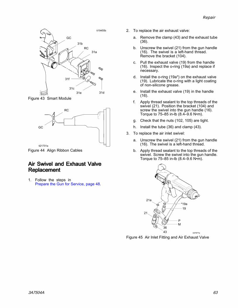
Repair
Figure 43 Smart Module
Figure 44 Align Ribbon Cables
AirAirAir SwivelSwivelSwivel andandand ExhaustExhaustExhaust ValveValveValveReplacementReplacementReplacement
1. Follow the steps inPrepare the Gun for Service, page 48.
2. To replace the air exhaust valve:
a. Remove the clamp (43) and the exhaust tube(36).
b. Unscrew the swivel (21) from the gun handle(16). The swivel is a left-hand thread.Remove the bracket (104).
c. Pull the exhaust valve (19) from the handle(16). Inspect the o-ring (19a) and replace ifnecessary.
d. Install the o-ring (19a*) on the exhaust valve(19). Lubricate the o-ring with a light coatingof non-silicone grease.
e. Install the exhaust valve (19) in the handle(16).
f. Apply thread sealant to the top threads of theswivel (21). Position the bracket (104) andscrew the swivel into the gun handle (16).Torque to 75–85 in-lb (8.4–9.6 N•m).
g. Check that the nuts (102, 105) are tight.h. Install the tube (36) and clamp (43).
3. To replace the air inlet swivel:
a. Unscrew the swivel (21) from the gun handle(16). The swivel is a left-hand thread.
b. Apply thread sealant to the top threads of theswivel. Screw the swivel into the gun handle.Torque to 75–85 in-lb (8.4–9.6 N•m).
Figure 45 Air Inlet Fitting and Air Exhaust Valve
3A7504A 63
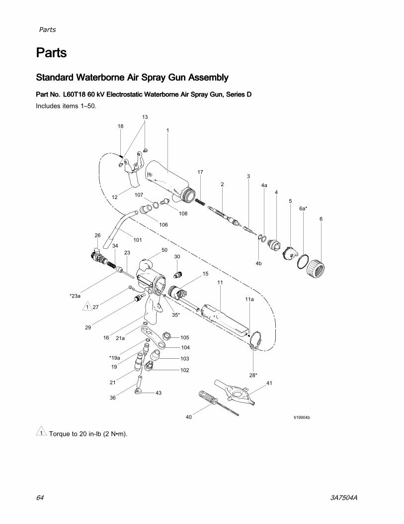
Parts
PartsPartsParts
StandardStandardStandard WaterborneWaterborneWaterborne AirAirAir SpraySpraySpray GunGunGun AssemblyAssemblyAssembly
PartPartPart No.No.No. L60T18L60T18L60T18 606060 kVkVkV ElectrostaticElectrostaticElectrostatic WaterborneWaterborneWaterborne AirAirAir SpraySpraySpray Gun,Gun,Gun, SeriesSeriesSeries DDD
Includes items 1–50.
1 Torque to 20 in-lb (2 N•m).
64 3A7504A
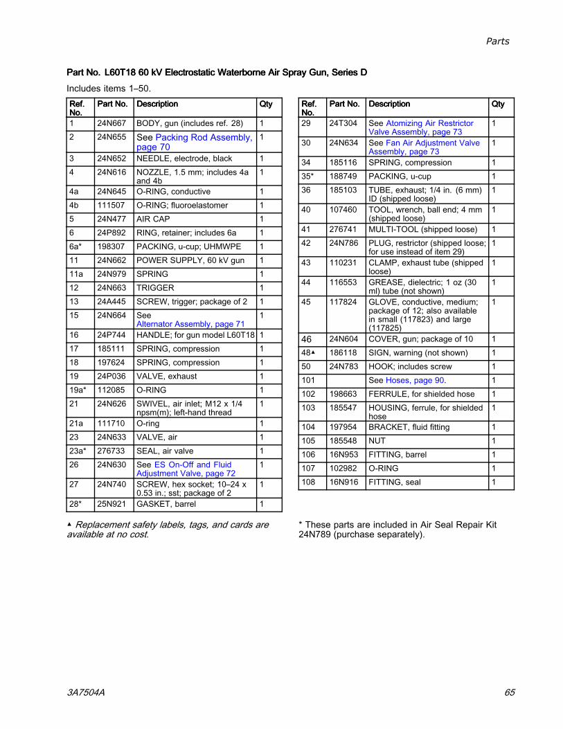
Parts
PartPartPart No.No.No. L60T18L60T18L60T18 606060 kVkVkV ElectrostaticElectrostaticElectrostatic WaterborneWaterborneWaterborne AirAirAir SpraySpraySpray Gun,Gun,Gun, SeriesSeriesSeries DDD
Includes items 1–50.Ref.Ref.Ref.No.No.No.
PartPartPart No.No.No. DescriptionDescriptionDescription QtyQtyQty
1 24N667 BODY, gun (includes ref. 28) 12 24N655 See Packing Rod Assembly,
page 701
3 24N652 NEEDLE, electrode, black 14 24N616 NOZZLE, 1.5 mm; includes 4a
and 4b1
4a 24N645 O-RING, conductive 14b 111507 O-RING; fluoroelastomer 15 24N477 AIR CAP 16 24P892 RING, retainer; includes 6a 16a* 198307 PACKING, u-cup; UHMWPE 111 24N662 POWER SUPPLY, 60 kV gun 111a 24N979 SPRING 112 24N663 TRIGGER 113 24A445 SCREW, trigger; package of 2 115 24N664 See
Alternator Assembly, page 711
16 24P744 HANDLE; for gun model L60T18 117 185111 SPRING, compression 118 197624 SPRING, compression 119 24P036 VALVE, exhaust 119a* 112085 O-RING 121 24N626 SWIVEL, air inlet; M12 x 1/4
npsm(m); left-hand thread1
21a 111710 O-ring 123 24N633 VALVE, air 123a* 276733 SEAL, air valve 126 24N630 See ES On-Off and Fluid
Adjustment Valve, page 721
27 24N740 SCREW, hex socket; 10–24 x0.53 in.; sst; package of 2
1
28* 25N921 GASKET, barrel 1
Ref.Ref.Ref.No.No.No.
PartPartPart No.No.No. DescriptionDescriptionDescription QtyQtyQty
29 24T304 See Atomizing Air RestrictorValve Assembly, page 73
1
30 24N634 See Fan Air Adjustment ValveAssembly, page 73
1
34 185116 SPRING, compression 135* 188749 PACKING, u-cup 136 185103 TUBE, exhaust; 1/4 in. (6 mm)
ID (shipped loose)1
40 107460 TOOL, wrench, ball end; 4 mm(shipped loose)
1
41 276741 MULTI-TOOL (shipped loose) 142 24N786 PLUG, restrictor (shipped loose;
for use instead of item 29)1
43 110231 CLAMP, exhaust tube (shippedloose)
1
44 116553 GREASE, dielectric; 1 oz (30ml) tube (not shown)
1
45 117824 GLOVE, conductive, medium;package of 12; also availablein small (117823) and large(117825)
1
46 24N604 COVER, gun; package of 10 148▲ 186118 SIGN, warning (not shown) 150 24N783 HOOK; includes screw 1101 See Hoses, page 90. 1102 198663 FERRULE, for shielded hose 1103 185547 HOUSING, ferrule, for shielded
hose1
104 197954 BRACKET, fluid fitting 1105 185548 NUT 1106 16N953 FITTING, barrel 1107 102982 O-RING 1108 16N916 FITTING, seal 1
▲ Replacement safety labels, tags, and cards areavailable at no cost.
* These parts are included in Air Seal Repair Kit24N789 (purchase separately).
3A7504A 65
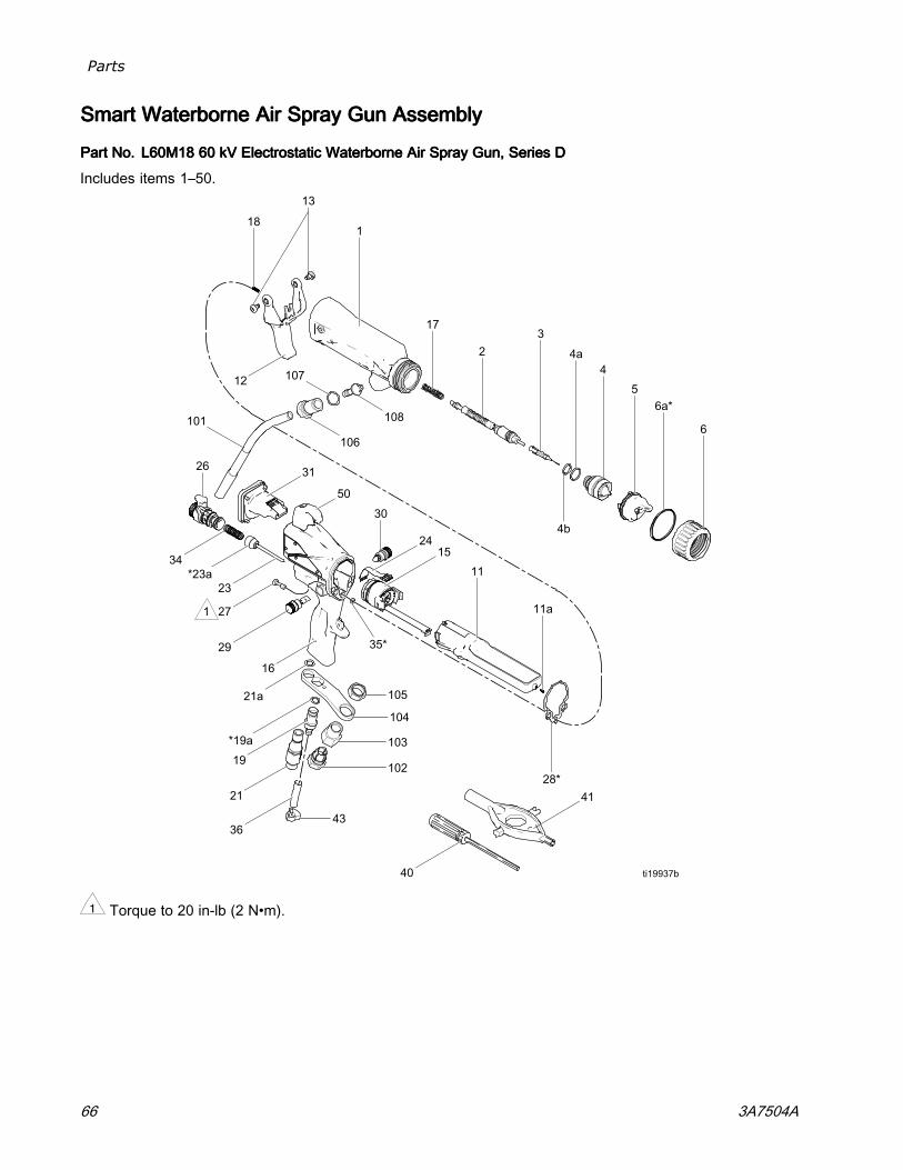
Parts
SmartSmartSmart WaterborneWaterborneWaterborne AirAirAir SpraySpraySpray GunGunGun AssemblyAssemblyAssembly
PartPartPart No.No.No. L60M18L60M18L60M18 606060 kVkVkV ElectrostaticElectrostaticElectrostatic WaterborneWaterborneWaterborne AirAirAir SpraySpraySpray Gun,Gun,Gun, SeriesSeriesSeries DDD
Includes items 1–50.
1 Torque to 20 in-lb (2 N•m).
66 3A7504A
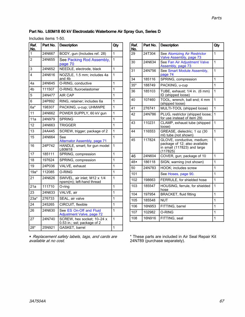
Parts
PartPartPart No.No.No. L60M18L60M18L60M18 606060 kVkVkV ElectrostaticElectrostaticElectrostatic WaterborneWaterborneWaterborne AirAirAir SpraySpraySpray Gun,Gun,Gun, SeriesSeriesSeries DDD
Includes items 1-50.Ref.Ref.Ref.No.No.No.
PartPartPart No.No.No. DescriptionDescriptionDescription QtyQtyQty
1 24N667 BODY, gun (Includes ref. 28) 12 24N655 See Packing Rod Assembly,
page 701
3 24N652 NEEDLE, electrode, black 14 24N616 NOZZLE, 1.5 mm; includes 4a
and 4b1
4a 24N645 O-RING, conductive 14b 111507 O-RING; fluoroelastomer 15 24N477 AIR CAP 16 24P892 RING, retainer; includes 6a 16a* 198307 PACKING, u-cup; UHMWPE 111 24N662 POWER SUPPLY, 60 kV gun 111a 24N979 SPRING 112 24N663 TRIGGER 113 24A445 SCREW, trigger; package of 2 115 24N664 See
Alternator Assembly, page 711
16 24P742 HANDLE, smart; for gun modelL60M18
1
17 185111 SPRING, compression 118 197624 SPRING, compression 119 24P036 VALVE, exhaust 119a* 112085 O-RING 121 24N626 SWIVEL, air inlet; M12 x 1/4
npsm(m); left-hand thread1
21a 111710 O-ring 123 24N633 VALVE, air 123a* 276733 SEAL, air valve 124 245265 CIRCUIT, flexible 126 24N630 See ES On-Off and Fluid
Adjustment Valve, page 721
27 24N740 SCREW, hex socket; 10–24 x0.53 in.; sst; package of 2
1
28* 25N921 GASKET, barrel 1
Ref.Ref.Ref.No.No.No.
PartPartPart No.No.No. DescriptionDescriptionDescription QtyQtyQty
29 24T304 See Atomizing Air RestrictorValve Assembly, page 73
1
30 24N634 See Fan Air Adjustment ValveAssembly, page 73
1
31 24N756 See Smart Module Assembly,page 74
1
34 185116 SPRING, compression 135* 188749 PACKING, u-cup 136 185103 TUBE, exhaust; 1/4 in. (6 mm)
ID (shipped loose)1
40 107460 TOOL, wrench, ball end; 4 mm(shipped loose)
1
41 276741 MULTI-TOOL (shipped loose) 142 24N786 PLUG, restrictor (shipped loose;
for use instead of item 29)1
43 110231 CLAMP, exhaust tube (shippedloose)
1
44 116553 GREASE, dielectric; 1 oz (30ml) tube (not shown)
1
45 117824 GLOVE, conductive, medium;package of 12; also availablein small (117823) and large(117825)
1
46 24N604 COVER, gun; package of 10 148▲ 186118 SIGN, warning (not shown) 150 24N783 HOOK; includes screw 1101 See Hoses, page 90. 1102 198663 FERRULE, for shielded hose 1103 185547 HOUSING, ferrule, for shielded
hose1
104 197954 BRACKET, fluid fitting 1105 185548 NUT 1106 16N953 FITTING, barrel 1107 102982 O-RING 1108 16N916 FITTING, seal 1
▲ Replacement safety labels, tags, and cards areavailable at no cost.
* These parts are included in Air Seal Repair Kit24N789 (purchase separately).
3A7504A 67
Parts
MoldMoldMold ReleaseReleaseRelease SmartSmartSmart AirAirAir SpraySpraySpray GunGunGun AssemblyAssemblyAssembly
PartPartPart No.No.No. L60M19L60M19L60M19 606060 kVkVkV ElectrostaticElectrostaticElectrostatic MoldMoldMold ReleaseReleaseRelease AirAirAir SpraySpraySpray Gun,Gun,Gun, SeriesSeriesSeries DDD
1 Torque to 20 in-lb (2 N•m).
68 3A7504A
Parts
PartPartPart No.No.No. L60M19L60M19L60M19 606060 kVkVkV ElectrostaticElectrostaticElectrostatic MoldMoldMold ReleaseReleaseRelease AirAirAir SpraySpraySpray Gun,Gun,Gun, SeriesSeriesSeries DDDRef.Ref.Ref.No.No.No.
PartPartPart No.No.No. DescriptionDescriptionDescription QtyQtyQty
1 24N667 BODY, gun (includes ref. 28) 12 24N655 See Packing Rod Assembly,
page 701
3 24N749 NEEDLE 14 24N748 NOZZLE, seat; includes 4a-4c 14a 24N645 O-RING, conductive 14b 111507 O-RING; fluoroelastomer 14c 24P893 RING, conductive 15 24N727 See Air Cap Assembly, page 74 15a 24N643 ELECTRODE; package of 5 16 245790 RING, retainer; includes 6a 16a* 198307 PACKING, u-cup; UHMWPE 110 AEMxxx
AEFxxxTIP ASSEMBLY; customer’schoice; includes item 27a
1
10a 183459 GASKET, tip 111 24N662 POWER SUPPLY, 60 kV gun 111a 24N979 SPRING 112 24N663 TRIGGER 113 24A445 SCREW, trigger; package of 2 115 24N664 See
Alternator Assembly, page 711
16 24P741 HANDLE, smart 117 185111 SPRING, compression 118 197624 SPRING, compression 119 24P036 VALVE, exhaust 119a* 112085 O-RING 121 24N626 SWIVEL, air inlet; M12 x 1/4
npsm(m); left-hand thread1
21a 111710 O-ring 123 24N633 VALVE, air 123a* 276733 SEAL, air valve 124 245265 CIRCUIT, flexible 126 24N630 See ES On-Off and Fluid
Adjustment Valve, page 721
Ref.Ref.Ref.No.No.No.
PartPartPart No.No.No. DescriptionDescriptionDescription QtyQtyQty
27 24N740 SCREW, hex socket; 10–24 x0.53 in.; sst; package of 2
1
28* 25N921 GASKET, barrel 129 24N792 ATOMIZING AIR
ADJUSTMENT VALVE1
30 24N634 See Fan Air Adjustment ValveAssembly, page 73
1
31 24N756 See Smart Module Assembly,page 74
1
34 185116 SPRING, compression 135* 188749 PACKING, u-cup 136 185103 TUBE, exhaust; 1/4 in. (6 mm)
ID (shipped loose)1
40 107460 TOOL, wrench, ball end; 4 mm(shipped loose)
1
41 276741 MULTI-TOOL (shipped loose) 142 24N786 PLUG, restrictor (shipped loose;
for use instead of item 29)1
43 110231 CLAMP, exhaust tube (shippedloose)
1
44 116553 GREASE, dielectric; 1 oz (30ml) tube (not shown)
1
45 117824 GLOVE, conductive, medium;package of 12; also availablein small (117823) and large(117825)
1
46 24N604 COVER, gun; package of 10 148▲ 186118 SIGN, warning (not shown) 150 24N783 HOOK; includes screw 1101 See Hoses, page 90. 1102 198663 FERRULE 1103 185547 HOUSING, ferrule 1104 197954 BRACKET, fluid fitting 1105 185548 NUT 1106 16N953 FITTING, barrel 1107 102982 O-RING 1108 16N916 FITTING, seal 1
▲ Replacement safety labels, tags, and cards areavailable at no cost.
* These parts are included in Air Seal Repair Kit24N789 (purchase separately).
3A7504A 69
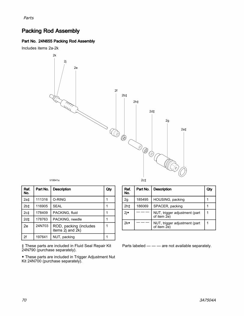
Parts
PackingPackingPacking RodRodRod AssemblyAssemblyAssembly
PartPartPart No.No.No. 24N65524N65524N655 PackingPackingPacking RodRodRod AssemblyAssemblyAssembly
Includes items 2a-2k
Ref.Ref.Ref.No.No.No.
PartPartPart No.No.No. DescriptionDescriptionDescription QtyQtyQty
2a‡ 111316 O-RING 1
2b‡ 116905 SEAL 1
2c‡ 178409 PACKING, fluid 1
2d‡ 178763 PACKING, needle 1
2e 24N703 ROD, packing (includesitems 2j and 2k)
1
2f 197641 NUT, packing 1
Ref.Ref.Ref.No.No.No.
PartPartPart No.No.No. DescriptionDescriptionDescription QtyQtyQty
2g 185495 HOUSING, packing 1
2h‡ 186069 SPACER, packing 1
2j◆ — —— NUT, trigger adjustment (partof item 2e)
1
2k◆ — —— NUT, trigger adjustment (partof item 2e)
1
‡ These parts are included in Fluid Seal Repair Kit24N790 (purchase separately).
◆ These parts are included in Trigger Adjustment NutKit 24N700 (purchase separately).
Parts labeled — —— are not available separately.
70 3A7504A
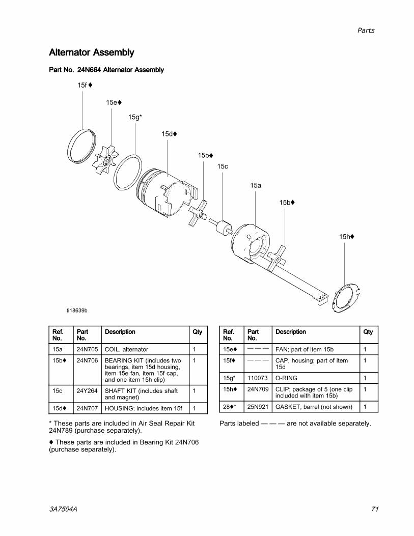
Parts
AlternatorAlternatorAlternator AssemblyAssemblyAssembly
PartPartPart No.No.No. 24N66424N66424N664 AlternatorAlternatorAlternator AssemblyAssemblyAssembly
Ref.Ref.Ref.No.No.No.
PartPartPartNo.No.No.
DescriptionDescriptionDescription QtyQtyQty
15a 24N705 COIL, alternator 1
15b♦ 24N706 BEARING KIT (includes twobearings, item 15d housing,item 15e fan, item 15f cap,and one item 15h clip)
1
15c 24Y264 SHAFT KIT (includes shaftand magnet)
1
15d♦ 24N707 HOUSING; includes item 15f 1
Ref.Ref.Ref.No.No.No.
PartPartPartNo.No.No.
DescriptionDescriptionDescription QtyQtyQty
15e♦ ——— FAN; part of item 15b 1
15f♦ ——— CAP, housing; part of item15d
1
15g* 110073 O-RING 1
15h♦ 24N709 CLIP; package of 5 (one clipincluded with item 15b)
1
28♦* 25N921 GASKET, barrel (not shown) 1
* These parts are included in Air Seal Repair Kit24N789 (purchase separately).
♦ These parts are included in Bearing Kit 24N706(purchase separately).
Parts labeled — —— are not available separately.
3A7504A 71
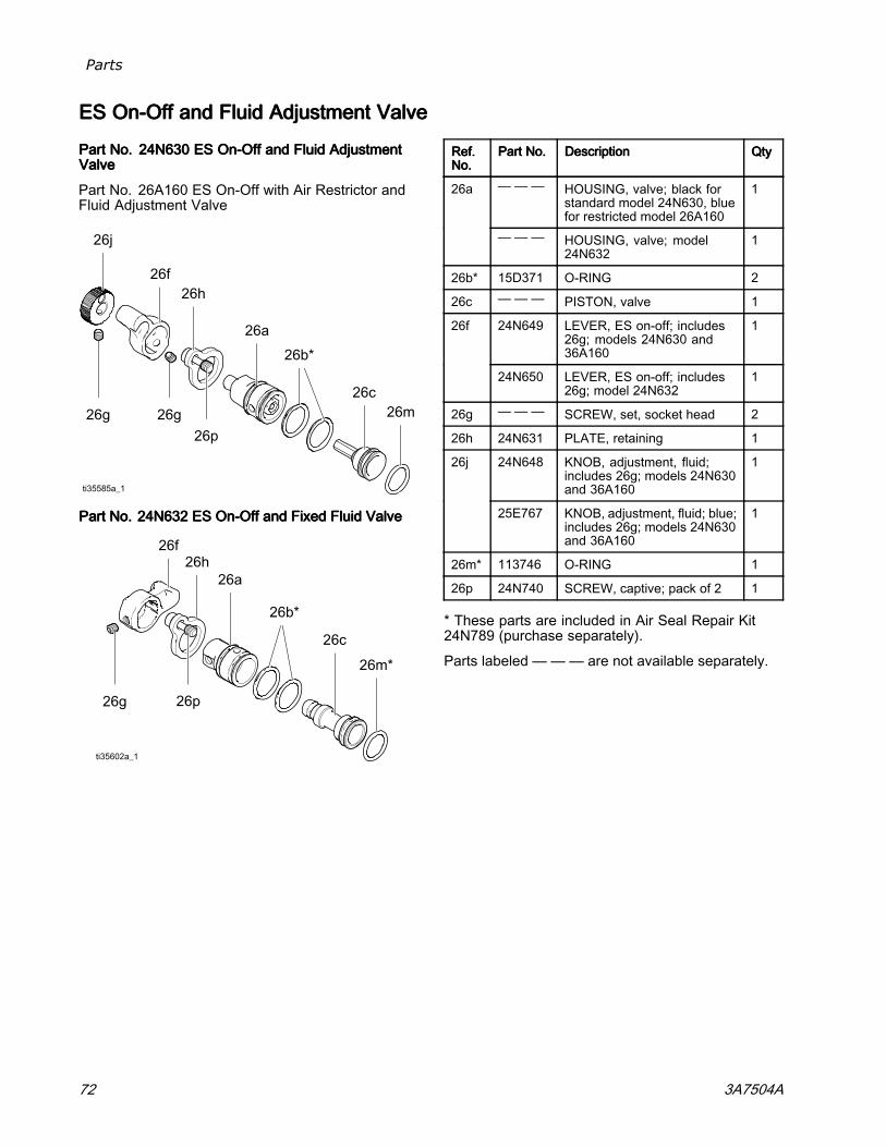
Parts
ESESES OnOnOn---OffOffOff andandand FluidFluidFluid AdjustmentAdjustmentAdjustment ValveValveValve
PartPartPart No.No.No. 24N63024N63024N630 ESESES On-OffOn-OffOn-Off andandand FluidFluidFluid AdjustmentAdjustmentAdjustmentValveValveValve
Part No. 26A160 ES On-Off with Air Restrictor andFluid Adjustment Valve
PartPartPart No.No.No. 24N63224N63224N632 ESESES On-OffOn-OffOn-Off andandand FixedFixedFixed FluidFluidFluid ValveValveValve
Ref.Ref.Ref.No.No.No.
PartPartPart No.No.No. DescriptionDescriptionDescription QtyQtyQty
— — — HOUSING, valve; black forstandard model 24N630, bluefor restricted model 26A160
126a
— — — HOUSING, valve; model24N632
1
26b* 15D371 O-RING 2
26c — — — PISTON, valve 1
24N649 LEVER, ES on-off; includes26g; models 24N630 and36A160
126f
24N650 LEVER, ES on-off; includes26g; model 24N632
1
26g — — — SCREW, set, socket head 2
26h 24N631 PLATE, retaining 1
24N648 KNOB, adjustment, fluid;includes 26g; models 24N630and 36A160
126j
25E767 KNOB, adjustment, fluid; blue;includes 26g; models 24N630and 36A160
1
26m* 113746 O-RING 1
26p 24N740 SCREW, captive; pack of 2 1
* These parts are included in Air Seal Repair Kit24N789 (purchase separately).
Parts labeled — —— are not available separately.
72 3A7504A
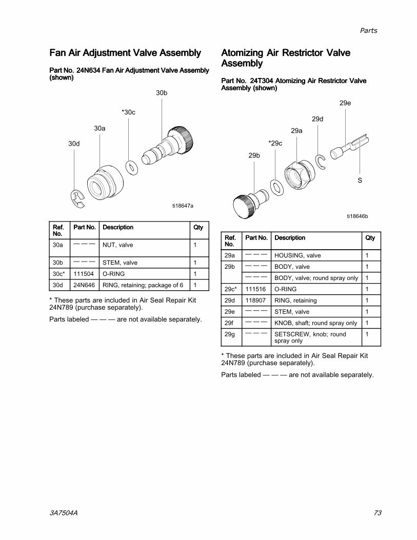
Parts
FanFanFan AirAirAir AdjustmentAdjustmentAdjustment ValveValveValve AssemblyAssemblyAssembly
PartPartPart No.No.No. 24N63424N63424N634 FanFanFan AirAirAir AdjustmentAdjustmentAdjustment ValveValveValve AssemblyAssemblyAssembly(shown)(shown)(shown)
Ref.Ref.Ref.No.No.No.
PartPartPart No.No.No. DescriptionDescriptionDescription QtyQtyQty
30a — —— NUT, valve 1
30b — —— STEM, valve 1
30c* 111504 O-RING 1
30d 24N646 RING, retaining; package of 6 1
* These parts are included in Air Seal Repair Kit24N789 (purchase separately).
Parts labeled — —— are not available separately.
AtomizingAtomizingAtomizing AirAirAir RestrictorRestrictorRestrictor ValveValveValveAssemblyAssemblyAssembly
PartPartPart No.No.No. 24T30424T30424T304 AtomizingAtomizingAtomizing AirAirAir RestrictorRestrictorRestrictor ValveValveValveAssemblyAssemblyAssembly (shown)(shown)(shown)
Ref.Ref.Ref.No.No.No.
PartPartPart No.No.No. DescriptionDescriptionDescription QtyQtyQty
29a — —— HOUSING, valve 1— —— BODY, valve 129b— —— BODY, valve; round spray only 1
29c* 111516 O-RING 1
29d 118907 RING, retaining 1
29e — —— STEM, valve 1
29f — — — KNOB, shaft; round spray only 1
29g — —— SETSCREW, knob; roundspray only
1
* These parts are included in Air Seal Repair Kit24N789 (purchase separately).
Parts labeled — —— are not available separately.
3A7504A 73
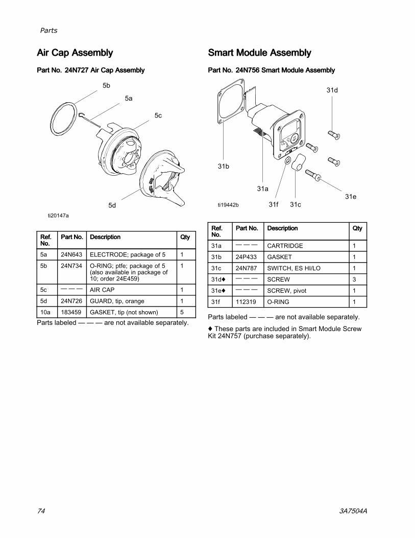
Parts
AirAirAir CapCapCap AssemblyAssemblyAssembly
PartPartPart No.No.No. 24N72724N72724N727 AirAirAir CapCapCap AssemblyAssemblyAssembly
Ref.Ref.Ref.No.No.No.
PartPartPart No.No.No. DescriptionDescriptionDescription QtyQtyQty
5a 24N643 ELECTRODE; package of 5 1
5b 24N734 O-RING; ptfe; package of 5(also available in package of10; order 24E459)
1
5c — —— AIR CAP 1
5d 24N726 GUARD, tip, orange 1
10a 183459 GASKET, tip (not shown) 5
Parts labeled — —— are not available separately.
SmartSmartSmart ModuleModuleModule AssemblyAssemblyAssembly
PartPartPart No.No.No. 24N75624N75624N756 SmartSmartSmart ModuleModuleModule AssemblyAssemblyAssembly
Ref.Ref.Ref.No.No.No.
PartPartPart No.No.No. DescriptionDescriptionDescription QtyQtyQty
31a — — — CARTRIDGE 1
31b 24P433 GASKET 1
31c 24N787 SWITCH, ES HI/LO 1
31d♦ — —— SCREW 3
31e♦ — —— SCREW, pivot 1
31f 112319 O-RING 1
Parts labeled — —— are not available separately.
♦ These parts are included in Smart Module ScrewKit 24N757 (purchase separately).
74 3A7504A
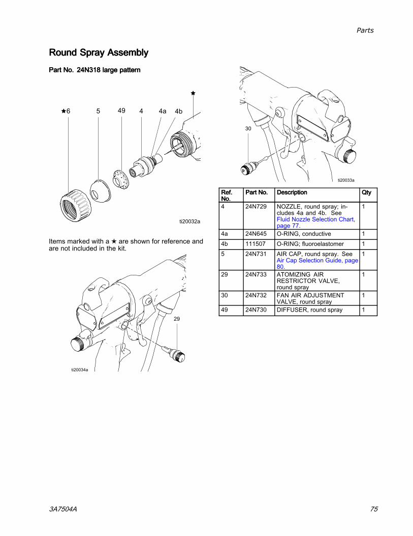
Parts
RoundRoundRound SpraySpraySpray AssemblyAssemblyAssembly
PartPartPart No.No.No. 24N31824N31824N318 largelargelarge patternpatternpattern
Items marked with a ★ are shown for reference andare not included in the kit.
Ref.Ref.Ref.No.No.No.
PartPartPart No.No.No. DescriptionDescriptionDescription QtyQtyQty
4 24N729 NOZZLE, round spray; in-cludes 4a and 4b. SeeFluid Nozzle Selection Chart,page 77.
1
4a 24N645 O-RING, conductive 14b 111507 O-RING; fluoroelastomer 15 24N731 AIR CAP, round spray. See
Air Cap Selection Guide, page80.
1
29 24N733 ATOMIZING AIRRESTRICTOR VALVE,round spray
1
30 24N732 FAN AIR ADJUSTMENTVALVE, round spray
1
49 24N730 DIFFUSER, round spray 1
3A7504A 75
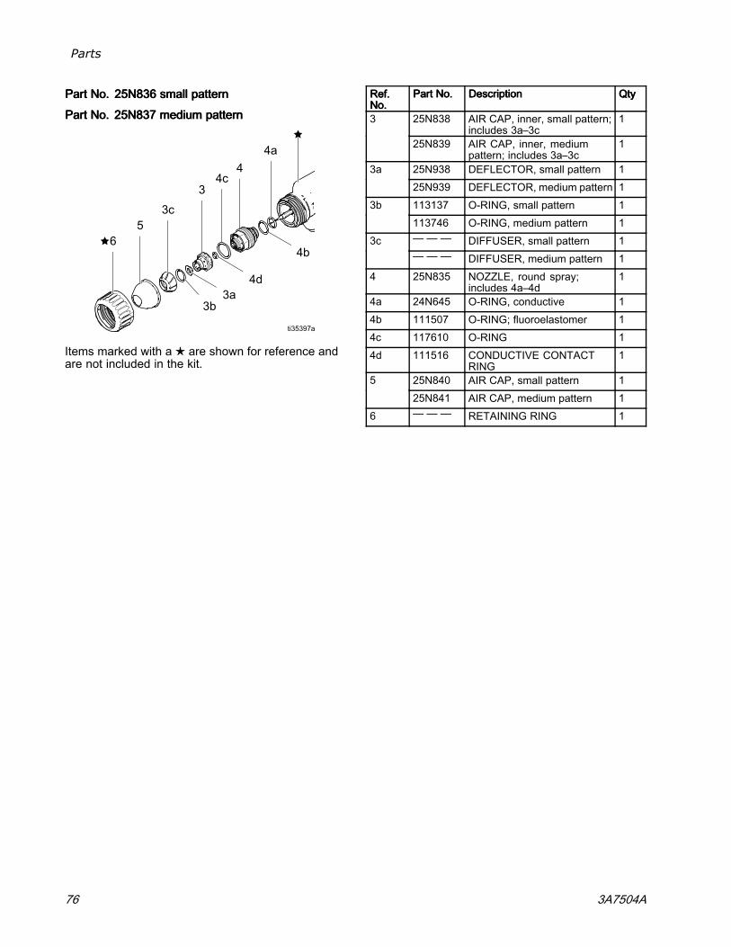
Parts
PartPartPart No.No.No. 25N83625N83625N836 smallsmallsmall patternpatternpattern
PartPartPart No.No.No. 25N83725N83725N837 mediummediummedium patternpatternpattern
Items marked with a ★ are shown for reference andare not included in the kit.
Ref.Ref.Ref.No.No.No.
PartPartPart No.No.No. DescriptionDescriptionDescription QtyQtyQty
25N838 AIR CAP, inner, small pattern;includes 3a–3c
13
25N839 AIR CAP, inner, mediumpattern; includes 3a–3c
1
25N938 DEFLECTOR, small pattern 13a25N939 DEFLECTOR, medium pattern 1113137 O-RING, small pattern 13b113746 O-RING, medium pattern 1— — — DIFFUSER, small pattern 13c— — — DIFFUSER, medium pattern 1
4 25N835 NOZZLE, round spray;includes 4a–4d
1
4a 24N645 O-RING, conductive 14b 111507 O-RING; fluoroelastomer 14c 117610 O-RING 14d 111516 CONDUCTIVE CONTACT
RING1
25N840 AIR CAP, small pattern 1525N841 AIR CAP, medium pattern 1
6 — — — RETAINING RING 1
76 3A7504A

Fluid Nozzles
FluidFluidFluid NozzlesNozzlesNozzles
FluidFluidFluid NozzleNozzleNozzle SelectionSelectionSelection ChartChartChart
To reduce the risk of an injury, follow the Pressure Relief Procedure, page 33, before removing or installinga fluid nozzle and/or air cap.
FluidFluidFluid NozzleNozzleNozzlePartPartPart No.No.No.
OrificeOrificeOrifice SizeSizeSizemmmmmm (in.)(in.)(in.)
ColorColorColor DescriptionDescriptionDescription
24N619 0.55 (.022) Black
24N613 0.75 (.029) Black
25N895 1.0 (.042) Green
25N896 1.2 (.047) Gray
24N616 1.5 (.055) Black
25N897 1.8 (.070) Brown
24N618 2.0 (.079) Black
StandardStandardStandard nozzlesnozzlesnozzles (STD)(STD)(STD)for standard coatings
25N831 1.0 (.042) Green
25N832 1.2 (.047) Gray
25N833 1.5 (.055) Black
25N834 1.8 (.070) Brown
PrecisionPrecisionPrecision highhighhigh wearwearwear nozzlesnozzlesnozzles (PHW)(PHW)(PHW)with hardened SST seat and damage resistant SST tip; forstandard coatings, abrasives, and metallics
24N620 0.75 (.029)
24N621 1.0 (.042)
24N622 1.2 (.047)
24N623 1.5 (.055)
24N624 1.8 (.070)
24N625 2.0 (.079)
Blue HighHighHigh wearwearwear nozzlesnozzlesnozzles (HW)(HW)(HW)with hardened ceramic seat, for abrasives and metallics
3A7504A 77
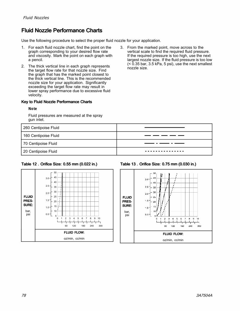
Fluid Nozzles
FluidFluidFluid NozzleNozzleNozzle PerformancePerformancePerformance ChartsChartsCharts
Use the following procedure to select the proper fluid nozzle for your application.
1. For each fluid nozzle chart, find the point on thegraph corresponding to your desired flow rateand viscosity. Mark the point on each graph witha pencil.
2. The thick vertical line in each graph representsthe target flow rate for that nozzle size. Findthe graph that has the marked point closest tothe thick vertical line. This is the recommendednozzle size for your application. Significantlyexceeding the target flow rate may result inlower spray performance due to excessive fluidvelocity.
3. From the marked point, move across to thevertical scale to find the required fluid pressure.If the required pressure is too high, use the nextlargest nozzle size. If the fluid pressure is too low(< 0.35 bar, 3.5 kPa, 5 psi), use the next smallestnozzle size.
KeyKeyKey tototo FluidFluidFluid NozzleNozzleNozzle PerformancePerformancePerformance ChartsChartsCharts
Note
Fluid pressures are measured at the spraygun inlet.
260 Centipoise Fluid
160 Centipoise Fluid
70 Centipoise Fluid
20 Centipoise Fluid
TableTableTable 121212 ... OrificeOrificeOrifice Size:Size:Size: 0.550.550.55 mmmmmm (0.022(0.022(0.022 in.)in.)in.)
50.5
1.0
1.5
2.0
2.5
3.0
0 1 2
60 120 180 240 300
3 4 5 6 7 8 9 10
10
15
20
25
30
35
40
45
50
FLUIDFLUIDFLUIDPRES-PRES-PRES-SURE:SURE:SURE:
bar,psi
FLUIDFLUIDFLUID FLOW:FLOW:FLOW:
oz/min, cc/min
TableTableTable 131313 ... OrificeOrificeOrifice Size:Size:Size: 0.750.750.75 mmmmmm (0.030(0.030(0.030 in.)in.)in.)
FLUIDFLUIDFLUIDPRES-PRES-PRES-SURE:SURE:SURE:
bar,psi
FLUIDFLUIDFLUID FLOW:FLOW:FLOW:
oz/min, cc/min
78 3A7504A
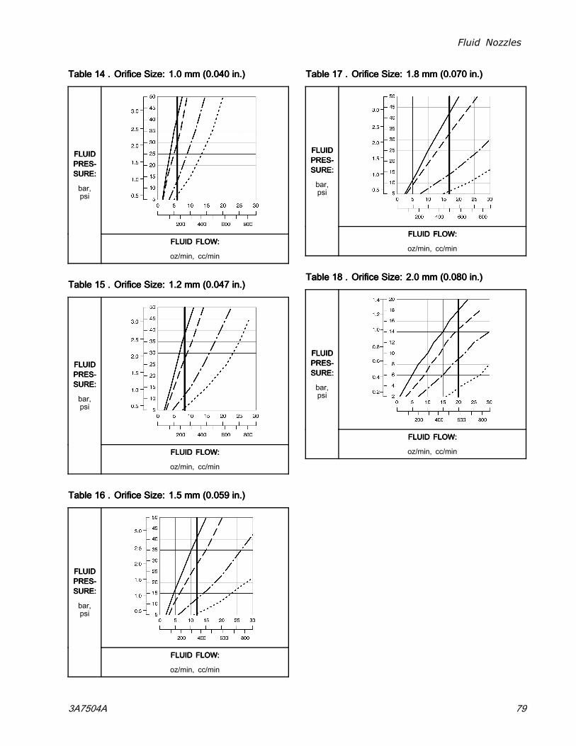
Fluid Nozzles
TableTableTable 141414 ... OrificeOrificeOrifice Size:Size:Size: 1.01.01.0 mmmmmm (0.040(0.040(0.040 in.)in.)in.)
FLUIDFLUIDFLUIDPRES-PRES-PRES-SURE:SURE:SURE:
bar,psi
FLUIDFLUIDFLUID FLOW:FLOW:FLOW:
oz/min, cc/min
TableTableTable 151515 ... OrificeOrificeOrifice Size:Size:Size: 1.21.21.2 mmmmmm (0.047(0.047(0.047 in.)in.)in.)
FLUIDFLUIDFLUIDPRES-PRES-PRES-SURE:SURE:SURE:
bar,psi
FLUIDFLUIDFLUID FLOW:FLOW:FLOW:
oz/min, cc/min
TableTableTable 161616 ... OrificeOrificeOrifice Size:Size:Size: 1.51.51.5 mmmmmm (0.059(0.059(0.059 in.)in.)in.)
FLUIDFLUIDFLUIDPRES-PRES-PRES-SURE:SURE:SURE:
bar,psi
FLUIDFLUIDFLUID FLOW:FLOW:FLOW:
oz/min, cc/min
TableTableTable 171717 ... OrificeOrificeOrifice Size:Size:Size: 1.81.81.8 mmmmmm (0.070(0.070(0.070 in.)in.)in.)
FLUIDFLUIDFLUIDPRES-PRES-PRES-SURE:SURE:SURE:
bar,psi
FLUIDFLUIDFLUID FLOW:FLOW:FLOW:
oz/min, cc/min
TableTableTable 181818 ... OrificeOrificeOrifice Size:Size:Size: 2.02.02.0 mmmmmm (0.080(0.080(0.080 in.)in.)in.)
FLUIDFLUIDFLUIDPRES-PRES-PRES-SURE:SURE:SURE:
bar,psi
FLUIDFLUIDFLUID FLOW:FLOW:FLOW:
oz/min, cc/min
3A7504A 79
Air Caps
AirAirAir CapsCapsCaps
AirAirAir CapCapCap SelectionSelectionSelection GuideGuideGuide
To reduce the risk of an injury, follow thePressure Relief Procedure, page 33, beforeremoving or installing a fluid nozzle and/or air cap.
The charts in this section can assist you in selectingan air cap.
• Keep in mind that more than one air cap can meetyour finish requirements.
• When selecting an air cap, consider coatingproperties, part geometry, pattern shape, patternsize, and operator preferences.
MeasurementsMeasurementsMeasurements
All air cap pattern shapes and lengths in the followingcharts were measured under the following conditions,unless otherwise noted:
Note
Pattern shape and length arematerial-dependent.
• Distance to target: 10 in. (254 mm)• Inlet air pressure: 50 psi (34 kPa, 3.4 bar)• Fan air: adjusted for maximum length• Fluid flow rate: 10 oz/min (300 cc/min)
80 3A7504A
Air Caps
PatternPatternPattern ShapeShapeShape
Pattern shapes are influenced by the material viscosity, flow rate, and air pressure settings. The gun may notmaintain the intended design shape under all conditions.
• RoundRoundRound patternspatternspatterns have a swirling, slow, round cone pattern for excellent finish and transfer efficiency.
• FanFanFan patternspatternspatterns have two styles: round ends and tapered ends.
– FanFanFan patternspatternspatterns withwithwith roundroundround endsendsends are versatile. They can be used in any application and are often the bestoption for smaller parts or cut-in painting.
– FanFanFan patternspatternspatterns withwithwith taperedtaperedtapered endsendsends are best for achieving even coating thickness with overlapping paintpasses.
3A7504A 81
Air Caps
GeneralGeneralGeneral FanFanFan PatternPatternPattern AirAirAir Caps:Caps:Caps: DescriptionsDescriptionsDescriptions
PartPartPart No.No.No. ColorColorColor DescriptionDescriptionDescription GuidelinesGuidelinesGuidelines forforfor UseUseUse
24N477 Black
24W479 Green
Standard Most versatile air cap. Recommended for most materials and applications. ClassA finish. Often used in waterborne applications.
24N438 Black Alternate Similar to the standard air cap with an alternate arrangement of atomizing air.
24N376 Black
24N276 Blue
24N277 Red
24N278 Green
Long Pattern Longest spray pattern, optimized for painting large parts with overlapping paintpasses. Often used in waterborne applications.
24N274 Black Short Pattern Shorter pattern, optimized for painting with overlapping passes.
GeneralGeneralGeneral FanFanFan PatternPatternPattern AirAirAir Caps:Caps:Caps: SpecificationsSpecificationsSpecifications
PartPartPart No.No.No. ColorColorColor DescriptionDescriptionDescription PatternPatternPatternShapeShapeShape
NominalNominalNominalPatternPatternPatternLengthLengthLengthin.in.in. (mm)(mm)(mm)
RecommendedRecommendedRecommendedFluidFluidFluid Viscosity*Viscosity*Viscosity*
RecommendedRecommendedRecommendedProductionProductionProductionRates**Rates**Rates**
Atom-Atom-Atom-izationizationization
Clean-Clean-Clean-linesslinessliness
24N477 Black
24W479 Green
Standard Roundend
15-17(381-432)
Light to medium Standard Best Good
24N438 Black Alternate Roundend
15-17(381-432)
Light to medium Standard Best Good
24N376 Black
24N276 Blue
24N277 Red
24N278 Green
Long Pattern Taperedend
17-19(432-483)
Light to medium Standard Better Better
24N274 Black Short Pattern Taperedend
12-14(305-356)
Light to medium Standard Good Best
*Fluid Viscosity, in centipoise (cp) at 70°F (21°C).Centipoise = centistokes x fluid specific gravity.
**Recommended Production Rates
Light to medium 20–70 cp Standard 300 cc/min to 500 cc/min (10 oz/minto 17 oz/min)
Medium to heavy 70–360 cp Low 100 cc/min to 300 cc/min (3 oz/minto 10 oz/min)
High solids 360+ cp High 500 cc/min to 600 cc/min (17 oz/minto 20 oz/min)
Very High 600 cc/min to 750 cc/min (20 oz/minto 25 oz/min)
82 3A7504A
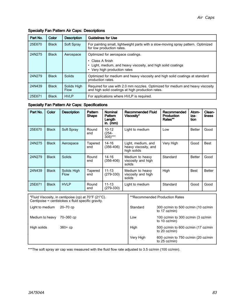
Air Caps
SpecialtySpecialtySpecialty FanFanFan PatternPatternPattern AirAirAir Caps:Caps:Caps: DescriptionsDescriptionsDescriptions
PartPartPart No.No.No. ColorColorColor DescriptionDescriptionDescription GuidelinesGuidelinesGuidelines forforfor UseUseUse
25E670 Black Soft Spray For painting small, lightweight parts with a slow-moving spray pattern. Optimizedfor low production rates.
24N275 Black Aerospace Optimized for aerospace coatings.
• Class A finish• Light, medium, and heavy viscosity, and high solid coatings• Very high production rates
24N279 Black Solids Optimized for medium and heavy viscosity and high solid coatings at standardproduction rates.
24N439 Black Solids HighFlow
Required for use with 2.0 mm nozzles. Optimized for medium and heavy viscosityand high solid coatings at high production rates.
25E671 Black HVLP For applications where HVLP is required.
SpecialtySpecialtySpecialty FanFanFan PatternPatternPattern AirAirAir Caps:Caps:Caps: SpecificationsSpecificationsSpecifications
PartPartPart No.No.No. ColorColorColor DescriptionDescriptionDescription PatternPatternPatternShapeShapeShape
NominalNominalNominalPatternPatternPatternLengthLengthLengthin.in.in. (mm)(mm)(mm)
RecommendedRecommendedRecommended FluidFluidFluidViscosity*Viscosity*Viscosity*
RecommendedRecommendedRecommendedProductionProductionProductionRates**Rates**Rates**
Atom-Atom-Atom-iza-iza-iza-tiontiontion
Clean-Clean-Clean-linesslinessliness
25E670 Black Soft Spray Roundend
10-12(254-305)***
Light to medium Low Better Good
24N275 Black Aerospace Taperedend
14-16(356-406)
Light, medium, andheavy viscosity, andhigh solids
Very High Good Best
24N279 Black Solids Roundend
14-16(356-406)
Medium to heavyviscosity and highsolids
Standard Better Good
24N439 Black Solids HighFlow
Taperedend
11-13(279-330)
Medium to heavyviscosity and highsolids
High Best Better
25E671 Black HVLP Roundend
11-13(279-330)
Light to medium Standard Good Good
*Fluid Viscosity, in centipoise (cp) at 70°F (21°C).Centipoise = centistokes x fluid specific gravity.
**Recommended Production Rates
Light to medium 20–70 cp Standard 300 cc/min to 500 cc/min (10 oz/minto 17 oz/min)
Medium to heavy 70–360 cp Low 100 cc/min to 300 cc/min (3 oz/minto 10 oz/min)
High solids 360+ cp High 500 cc/min to 600 cc/min (17 oz/minto 20 oz/min)
Very High 600 cc/min to 750 cc/min (20 oz/minto 25 oz/min)
***The soft spray air cap was measured with the fluid flow rate adjusted to 3.5 oz/min (100 cc/min).
3A7504A 83
Air Caps
RoundRoundRound PatternPatternPattern AirAirAir Caps:Caps:Caps: DescriptionsDescriptionsDescriptions
PartPartPart No.No.No. ColorColorColor DescriptionDescriptionDescription GuidelinesGuidelinesGuidelines forforfor UseUseUse
24N318 Black LargePattern
Conventional round pattern design for larger patterns up to 8 in (20 cm). Swirling,slow, round cone pattern for excellent finish and transfer efficiency.
25N837 Black MediumPattern
Dual inner and outer atomizing air design for improved atomization at low air flows.For medium patterns up to 6 inches (15cm). Swirling, slow, round cone pattern forexcellent finish and transfer efficiency.
25N836 Black SmallPattern
Dual inner and outer atomizing air design for improved atomization at low air flows.For small patterns up to 4 inches (10cm). Swirling, slow, round cone pattern forexcellent finish and transfer efficiency.
RoundRoundRound PatternPatternPattern AirAirAir Caps:Caps:Caps: SpecificationsSpecificationsSpecifications
PartPartPart No.No.No. ColorColorColor DescriptionDescriptionDescription PatternPatternPatternShapeShapeShape
NominalNominalNominalPatternPatternPatternDiameterDiameterDiameterin.in.in. (mm)(mm)(mm)
RecommendedRecommendedRecommended FluidFluidFluidViscosity*Viscosity*Viscosity*
RecommendedRecommendedRecommendedProductionProductionProductionRates**Rates**Rates**
Atom-Atom-Atom-iza-iza-iza-tiontiontion
Clean-Clean-Clean-linesslinessliness
24N318 Black Large Pattern Roundend
8 (203) Light to medium Low Good Good
25N837 Black MediumPattern
Roundend
6 (152) Light to medium Low Better Good
25N836 Black Small Pattern Roundend
4 (102) Light to medium Low Better Good
*Fluid Viscosity, in centipoise (cp) at 70°F (21°C).Centipoise = centistokes x fluid specific gravity.
**Recommended Production Rates
Light to medium 20–70 cp Standard 300 cc/min to 500 cc/min (10 oz/minto 17 oz/min)
Medium to heavy 70–360 cp Low 100 cc/min to 300 cc/min (3 oz/minto 10 oz/min)
High solids 360+ cp High 500 cc/min to 600 cc/min (17 oz/minto 20 oz/min)
Very High 600 cc/min to 750 cc/min (20 oz/minto 25 oz/min)
84 3A7504A
Air Caps
AirAirAir ConsumptionConsumptionConsumption ChartsChartsCharts
Air consumption applies to the complete gun.
KeyKeyKey tototo AirAirAir ConsumptionConsumptionConsumption ChartsChartsCharts
TESTTESTTEST CONDITIONS:CONDITIONS:CONDITIONS: Fan valve fully open (unless otherwise noted), atomization valve fully open (unlessotherwise noted), 85kv gun.
5/16 in. x 25 ft (8 mm x 7.6 m) hose
5/16 in. x 50 ft (8 mm x 15.2 m) hose
TableTableTable 191919 24N477,24N477,24N477, 24W279,24W279,24W279, 24N279,24N279,24N279, 24N376,24N376,24N376, andandand24N43824N43824N438 AirAirAir CapCapCap
600
5
10
15
20
25
62 64 66 68 70 72 74 76 78
AIRAIRAIR CON-CON-CON-SUMPTIONSUMPTIONSUMPTION
scfm
WALLWALLWALL PRESSUREPRESSUREPRESSURE
psi
TableTableTable 202020 24N274,24N274,24N274, 24N275,24N275,24N275, andandand 24N43924N43924N439 AirAirAir CapCapCap
50 55 60 65 70 750
5
10
15
20
25
80
AIRAIRAIR CON-CON-CON-SUMPTIONSUMPTIONSUMPTION
scfm
WALLWALLWALL PRESSUREPRESSUREPRESSURE
psi
TableTableTable 212121 25E67025E67025E670 andandand 25E67125E67125E671 AirAirAir CapCapCap
50
2
0
4
6
8
10
12
14
16
18
55 60 65 70 75 80 85
AIRAIRAIR CON-CON-CON-SUMPTIONSUMPTIONSUMPTION
scfm
WALLWALLWALL PRESSUREPRESSUREPRESSURE
psi
Note
25E670: Atomization valve openedone turn from close accordingto soft spray gun setup. SeeSoft Spray Gun Setup Procedure, page 24.
25E671: Fan valve opened two turns fromclose. Atomization valve opened one turnfrom close according to HVLP gun setup.See HVLP Gun Setup Procedure, page 25.
3A7504A 85
Spray Tip Selection Chart (Model L60M19 MRG Gun Only)
SpraySpraySpray TipTipTip SelectionSelectionSelection ChartChartChart (Model(Model(Model L60M19L60M19L60M19 MRGMRGMRG GunGunGunOnly)Only)Only)
AEMAEMAEM FineFineFine FinishFinishFinish SpraySpraySpray TipsTipsTips
Recommended for high finish quality applications at low and medium pressures. Order desired tip, PartPartPart No.No.No.AEMxxx,AEMxxx,AEMxxx, where xxx = 3–digit number from the matrix below.
FluidFluidFluid OutputOutputOutputflflfl oz/minoz/minoz/min (l/min)(l/min)(l/min)
MaximumMaximumMaximum PatternPatternPattern WidthWidthWidth atatat 121212 in.in.in. (305(305(305 mm)mm)mm)in.in.in. (mm)(mm)(mm)
2–42–42–4(50–(50–(50–100)100)100)
4–64–64–6(100–(100–(100–150)150)150)
666---888(150(150(150---200)200)200)
888---101010(200(200(200---250)250)250)
101010---121212(250(250(250---300)300)300)
121212---141414(300(300(300---350)350)350)
141414---161616(350(350(350---400)400)400)
161616---181818(400(400(400---450)450)450)
OrificeOrificeOrificeSizeSizeSizein.in.in.
(mm)(mm)(mm)atatat 600600600psipsipsi (4.1(4.1(4.1MPa,MPa,MPa,414141 bar)bar)bar)
atatat 100010001000psipsipsi (7.0(7.0(7.0MPa,MPa,MPa,707070 bar)bar)bar) SpraySpraySpray TipTipTip
0.007(0.178)
4.0(0.1)
5.2(0.15)
107 207 307
0.009(0.229)
7.0(0.2)
9.1(0.27)
209 309 409 509 609
0.011(0.279)
10.0(0.3)
13.0(0.4)
211 311 411 511 611 711 811
0.013(0.330)
13.0(0.4)
16.9(0.5)
213 313 413 513 613 713 813
0.015(0.381)
17.0(0.5)
22.0(0.7)
215 315 415 515 615 715 815
0.017(0.432)
22.0(0.7)
28.5(0.85)
217 317 417 517 617 717
0.019(0.483)
28.0(0.8)
36.3(1.09)
319 419 519 619 719
0.021(0.533)
35.0(1.0)
45.4(1.36)
421 521 621 721 821
0.023(0.584)
40.0(1.2)
51.9(1.56)
423 523 623 723 823
0.025(0.635)
50.0(1.5)
64.8(1.94)
425 525 625 725 825
0.029(0.736)
68.0(1.9)
88.2(2.65)
829
0.031(0.787)
78.0(2.2)
101.1(3.03)
431 631 831
0.033(0.838)
88.0(2.5)
114.1(3.42)
833
0.037(0.939)
108.0(3.1)
140.0(4.20)
737
0.039(0.990)
118.0(3.4)
153.0(4.59)
539
* Tips are tested in water.Fluid output (Q) at other pressures (P) can be calculated by this formula: Q = (0.041) (QT) where QT = fluidoutput (fl oz/min) at 600 psi from the above table for the selected orifice size.
86 3A7504A
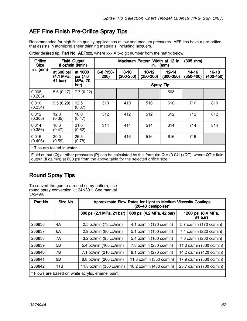
Spray Tip Selection Chart (Model L60M19 MRG Gun Only)
AEFAEFAEF FineFineFine FinishFinishFinish PrePrePre---OrificeOrificeOrifice SpraySpraySpray TipsTipsTips
Recommended for high finish quality applications at low and medium pressures. AEF tips have a pre-orificethat assists in atomizing sheer thinning materials, including lacquers.
Order desired tip, PartPartPart No.No.No. AEFxxx,AEFxxx,AEFxxx, where xxx = 3–digit number from the matrix below.
FluidFluidFluid OutputOutputOutputflflfl oz/minoz/minoz/min (l/min)(l/min)(l/min)
MaximumMaximumMaximum PatternPatternPattern WidthWidthWidth atatat 121212 in.in.in. (305(305(305 mm)mm)mm)in.in.in. (mm)(mm)(mm)
666---888 (150(150(150---200)200)200)
888---101010(200(200(200---250)250)250)
101010---121212(250(250(250---300)300)300)
121212---141414(300(300(300---350)350)350)
141414---161616(350(350(350---400)400)400)
161616---181818(400(400(400---450)450)450)
OrificeOrificeOrificeSizeSizeSize
in.in.in. (mm)(mm)(mm)atatat 600600600 psipsipsi(4.1(4.1(4.1 MPa,MPa,MPa,414141 bar)bar)bar)
atatat 100010001000psipsipsi (7.0(7.0(7.0MPa,MPa,MPa, 707070bar)bar)bar) SpraySpraySpray TipTipTip
0.008(0.203)
5.6 (0.17) 7.7 (0.22) 608
0.010(0.254)
9.5 (0.28) 12.5(0.37)
310 410 510 610 710 810
0.012(0.305)
12.0(0.35)
16.0(0.47)
312 412 512 612 712 812
0.014(0.356)
16.0(0.47)
21.0(0.62)
314 414 514 614 714 814
0.016(0.406)
20.0(0.59)
26.5(0.78)
416 516 616 716
* Tips are tested in water.
Fluid output (Q) at other pressures (P) can be calculated by this formula: Q = (0.041) (QT) where QT = fluidoutput (fl oz/min) at 600 psi from the above table for the selected orifice size.
RoundRoundRound SpraySpraySpray TipsTipsTips
To convert the gun to a round spray pattern, useround spray conversion kit 24N391. See manual3A2499.
ApproximateApproximateApproximate FlowFlowFlow RatesRatesRates forforfor LightLightLight tototo MediumMediumMedium ViscosityViscosityViscosity CoatingsCoatingsCoatings(20–40(20–40(20–40 centipoise)*centipoise)*centipoise)*
PartPartPart No.No.No. SizeSizeSize No.No.No.
300300300 psipsipsi (2.1(2.1(2.1 MPa,MPa,MPa, 212121 bar)bar)bar) 600600600 psipsipsi (4.2(4.2(4.2 MPa,MPa,MPa, 424242 bar)bar)bar) 120012001200 psipsipsi (8.4(8.4(8.4 MPa,MPa,MPa,848484 bar)bar)bar)
236836 4A 2.5 oz/min (73 cc/min) 4.1 oz/min (120 cc/min) 5.7 oz/min (170 cc/min)
236837 6A 2.9 oz/min (86 cc/min) 5.1 oz/min (150 cc/min) 7.4 oz/min (220 cc/min)
236838 7A 3.2 oz/min (95 cc/min) 5.4 oz/min (160 cc/min) 7.8 oz/min (230 cc/min)
236839 5B 5.4 oz/min (160 cc/min) 7.8 oz/min (230 cc/min) 11.0 oz/min (330 cc/min)
236840 7B 7.1 oz/min (210 cc/min) 9.1 oz/min (270 cc/min) 14.2 oz/min (420 cc/min)
236841 9B 8.8 oz/min (260 cc/min) 11.8 oz/min (350 cc/min) 17.9 oz/min (530 cc/min)
236842 11B 11.8 oz/min (350 cc/min) 16.2 oz/min (480 cc/min) 23.7 oz/min (700 cc/min)
* Flows are based on white acrylic, enamel paint.
3A7504A 87
Repair Kits and Accessories
RepairRepairRepair KitsKitsKits andandand AccessoriesAccessoriesAccessoriesPartPartPart No.No.No. DescriptionDescriptionDescription
24N789 Air Seal Repair Kit
24N790 Fluid Seal Repair Kit
24N706 Alternator Bearing Repair Kit
GunGunGun AccessoriesAccessoriesAccessories
GeneralGeneralGeneral AccessoriesAccessoriesAccessories
PartPartPart No.No.No. DescriptionDescriptionDescription
105749 Cleaning Brush
111265 Non-silicone Lubricant, 4 oz (113 g)
116553 Dielectric Grease. 1 oz (30 ml)
24N604 Gun Covers, box of 10
24N758 Display Covers. Keeps Smart displayclean. Package of 5.
TriggerTriggerTrigger andandand GripGripGrip AccessoriesAccessoriesAccessories
PartPartPart No.No.No. DescriptionDescriptionDescription
24N633 Plastic Trigger Kit
24P170 Metal Trigger Kit
24P171 Four Finger Trigger Kit, to convertPro Xp air spray guns to a four fingertrigger
24N520 Comfort Grip. Snap-on gripincreases handle size to reduceoperator fatigue. Medium size.
24N521 Comfort Grip. Snap-on gripincreases handle size to reduceoperator fatigue. Large size.
AtomizingAtomizingAtomizing AirAirAir ValveValveValve AccessoriesAccessoriesAccessories
PartPartPart No.No.No. DescriptionDescriptionDescription
24N636 Low Profile Atomizing Air RestrictorValve (adjusted with a hex tool)
AdapterAdapterAdapter andandand FittingFittingFitting AccessoriesAccessoriesAccessories
PartPartPart No.No.No. DescriptionDescriptionDescription
112534 Air Line Quick Disconnect Fitting
185105 Non-swivel Air Inlet; 1/4–18 npsm(m)(left-hand thread)
185493 Air Hose Adapter; 1/4 npt(m) x1/4–18 npsm(m) (left-hand thread)
24N642 Ball Swivel, for gun air inlet; 1/4npsm (left-hand thread)
224754 Valve, ball 1/4 npsm (left-handthread)
ESESES On/OffOn/OffOn/Off andandand FluidFluidFluid AdjustmentAdjustmentAdjustment ValveValveValve AccessoriesAccessoriesAccessories
PartPartPart No.No.No. DescriptionDescriptionDescription
26A160 ES On/Off Valve Restrictor for highatomizing air applications. Usethis accessory if the turbine lightindicator is red and you want tomaintain a higher application airpressure. Install the kit, then adjustthe pressure as needed to ensurethe indicator remains green.
24P634 ES Always ON and fluid adjustmentvalve. When this valve is installed,the electrostatics are on anytime airpressure is supplied to the gun. Fluidadjustment is possible. Must be usedwith 224754 ball valve installed at thegun air inlet. See manual 3A6840.
24N630 ES On-Off and Fluid AdjustmentValve
24N632 ES On-Off and Fixed Fluid Valve.Use to extend electrode and nozzlelife in applications with abrasive,metallic, and extremely abrasivematerials.
FanFanFan AirAirAir AdjustmentAdjustmentAdjustment ValveValveValve AccessoriesAccessoriesAccessories
PartPartPart No.No.No. DescriptionDescriptionDescription
24N634 Standard fan air adjustment valve
24N732 Fan air adjustment valve for largepattern round spray
24P172 Quick adjust fan valve for quickchange of fan size
25N919 Quick adjust fan valve with springreturn
88 3A7504A
Repair Kits and Accessories
RoundRoundRound SpraySpraySpray AccessoriesAccessoriesAccessories
PartPartPart No.No.No. DescriptionDescriptionDescription
24N318 Round Spray Kit, large pattern, toconvert a standard air spray gun toa round spray air cap. See manual3A2498.
25N837 Round Spray Kit, medium pattern, toconvert a standard air spray gun toa round spray air cap. See manual3A6829.
25N836 Round Spray Kit, small pattern, toconvert a standard air spray gun toa round spray air cap. See manual3A6829.
OperatorOperatorOperator AccessoriesAccessoriesAccessories
PartPartPart No.No.No. DescriptionDescriptionDescription
117823 Conductive Gloves, box of 12 (small)
117824 Conductive Gloves, box of 12(medium)
117825 Conductive Gloves, box of 12 (large)
SignsSignsSigns
PartPartPart No.No.No. DescriptionDescriptionDescription
16P802 English Warning Sign, available atno charge from Graco
16P798 English Daily Care Sign
16P799 English Setup Sign
SystemSystemSystem AccessoriesAccessoriesAccessories
PartPartPart No.No.No. DescriptionDescriptionDescription
222011 Ground Wire and Clamp
24N528 Gun Flush Box Adapter for 60 kVand 85 kV guns. To convert existinggun flush boxes to hold Pro Xp guns.See manual 309227.
24N529 Gun Flush Box Adapter for 40 kVguns. To convert existing gun flushboxes to hold Pro Xp guns. Seemanual 309227.
24P312 Gun Washer Kit. To convert existinggun washers to clean Pro Xp guns.See manual 308393.
TestTestTest EquipmentEquipmentEquipment
PartPartPart No.No.No. DescriptionDescriptionDescription
241079 Megohmmeter. 500 V output,0.01–2000 megohms. Use forground continuity and gun resistancetests.NotNotNot forforfor useuseuse ininin hazardoushazardoushazardous areas.areas.areas.
245277 Test Fixture, High Voltage Probe,and kV Meter. Use to test theelectrostatic voltage of the gun, andthe condition of the alternator andpower supply when being serviced.See manual 309455.
24R038 Voltage Tester Conversion Kit.Converts the 245277 Test Fixture foruse with the Pro Xp Gun alternator.See manual 406999.
25E919 HVLP Air Cap Verification Kit. Useto verify air pressures in air capsin HVLP applications. For usewith 25E671 air cap. See manual3A6833.
3A7504A 89
Repair Kits and Accessories
HosesHosesHoses
GroundedGroundedGrounded AirAirAir HosesHosesHoses
100 psi (0.7 MPa, 7 bar) Maximum Working Pressure0.315 in. (8 mm) ID; 1/4 npsm(f) x 1/4 npsm(f)left-hand thread
PartPartPart No.No.No. DescriptionDescriptionDescription
GroundedGroundedGrounded AirAirAir HoseHoseHose withwithwith stainlessstainlessstainless steelsteelsteel braidbraidbraidgroundgroundground pathpathpath (Red)(Red)(Red)
235068 6 ft (1.8 m)
235069 15 ft (4.6 m)
235070 25 ft (7.6 m)
235071 36 ft (11 m)
235072 50 ft (15 m)
235073 75 ft (23 m)
235074 100 ft (30.5 m)
FluidFluidFluid HosesHosesHoses
100 psi (0.7 MPa, 7.0 bar) Maximum WorkingPressure1/4 in. (6 mm) ID
PartPartPart No.No.No. DescriptionDescriptionDescription
ForForFor gungungun modelsmodelsmodels L60T18,L60T18,L60T18, L60M18,L60M18,L60M18, L60M19;L60M19;L60M19;includesincludesincludes 102–108102–108102–108
UseUseUse forforfor WB100WB100WB100 onlyonlyonly
24M732 Waterborne Fluid Hose, 25 ft (7.6 m)
25N916 Waterborne Fluid Hose Assembly,50 ft (15.2 m)
UseUseUse forforfor HydroShieldHydroShieldHydroShield onlyonlyonly
25R002 Waterborne Fluid Hose, 25 ft (7.6 m)
25R003 Waterborne Fluid Hose, 36 ft (11 m)
25R004 Waterborne Fluid Hose, 50 ft (15 m)
25R005 Waterborne Fluid Hose, 75 ft (23 m)
25R006 Waterborne Fluid Hose, 100 ft (31m)
90 3A7504A
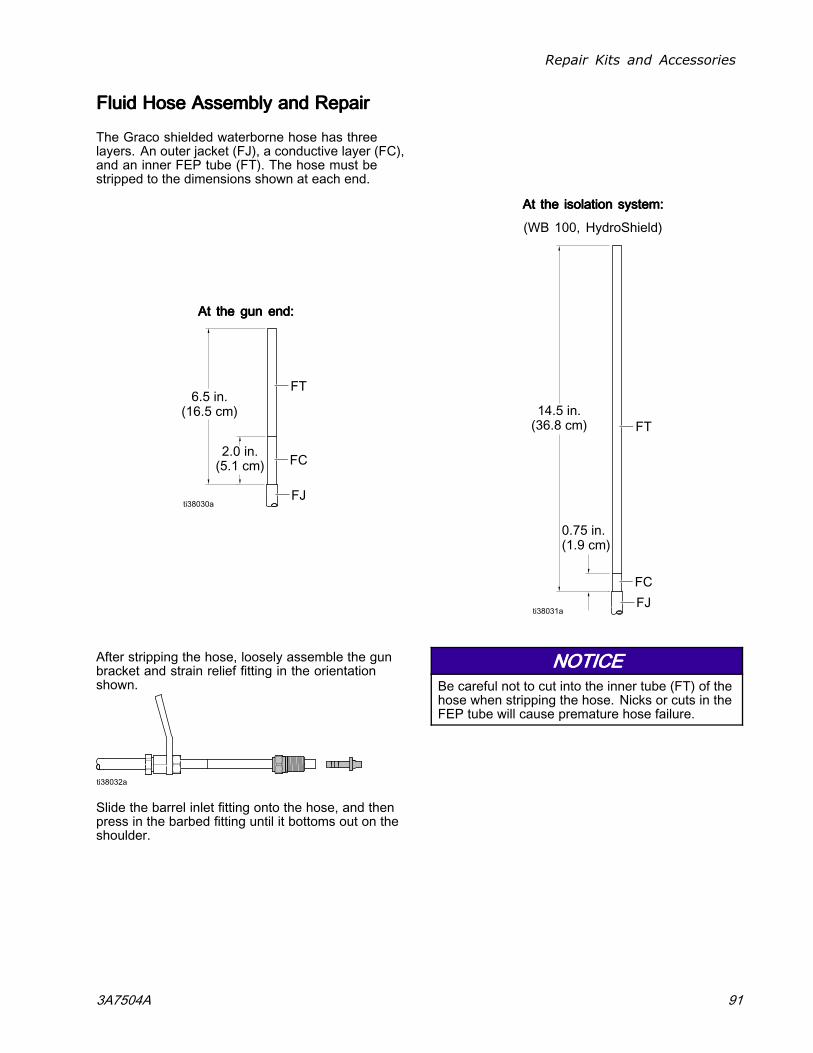
Repair Kits and Accessories
FluidFluidFluid HoseHoseHose AssemblyAssemblyAssembly andandand RepairRepairRepair
The Graco shielded waterborne hose has threelayers. An outer jacket (FJ), a conductive layer (FC),and an inner FEP tube (FT). The hose must bestripped to the dimensions shown at each end.
AtAtAt thethethe gungungun end:end:end:
AtAtAt thethethe isolationisolationisolation system:system:system:
(WB 100, HydroShield)
After stripping the hose, loosely assemble the gunbracket and strain relief fitting in the orientationshown.
Slide the barrel inlet fitting onto the hose, and thenpress in the barbed fitting until it bottoms out on theshoulder.
NOTICENOTICENOTICEBe careful not to cut into the inner tube (FT) of thehose when stripping the hose. Nicks or cuts in theFEP tube will cause premature hose failure.
3A7504A 91
Ignitability of Coating Materials
IgnitabilityIgnitabilityIgnitability ofofof CoatingCoatingCoating MaterialsMaterialsMaterialsPer EN 50059
From the Physikalisch-Technische Bundesanstalt, Braunschweig, Germany, June 26, 2019.
GeneralGeneralGeneral
The fire and explosion protection of spraying systems can be facilitated considerably when processingcoating materials with a low portion of solvents and a high flash point (generally water-based paints),provided that the spray cloud of the coating materials are considered to be non-ignitable. Substantialresearch has shown that the ignitability of spray clouds depends on the composition of the coating materialsmade mainly of water, solvents, and solids. The following classification has been established:
NonNonNon---ignitableignitableignitable coatingcoatingcoating materialsmaterialsmaterials
Coating materials of this group have the following composition:
[% H2O] > 1, 70 + [% LM] + 0,96 x [% ORG], (all in % by weight)
where
H2O: water;
LM: the entire liquid phase, including liquids with flash points above 60 °C and those liquids notnotnot listed inthe safety data sheet, in which case the entire liquid phase is ignitable in the sprayed state;
ORG: solid phase which is ignitable in the sprayed state (ignitable inorganic or ignitable organic solids)including the solids which have an ignitable inorganic or ignitable organic coating.
Non-ignitable coating materials act like water in the liquid phase and in the sprayed state. If the rinsing andthinner liquids correspond to this category, too, no explosion protection is necessary. Coating materials ofthis group are classified as being non-ignitable liquid coating material.
A fire extinguishing equipment is not required for spraying systems processing coating materials which areclassified to be non-ignitable. However, this does not affect the fire protection as a whole. Even thesecoating materials may resume ignitability after being partially dried. Moreover, water-based coating materialswill burn when strongly exposed to a fire which had been initiated by other sources, and thus present acertain fire load.
92 3A7504A
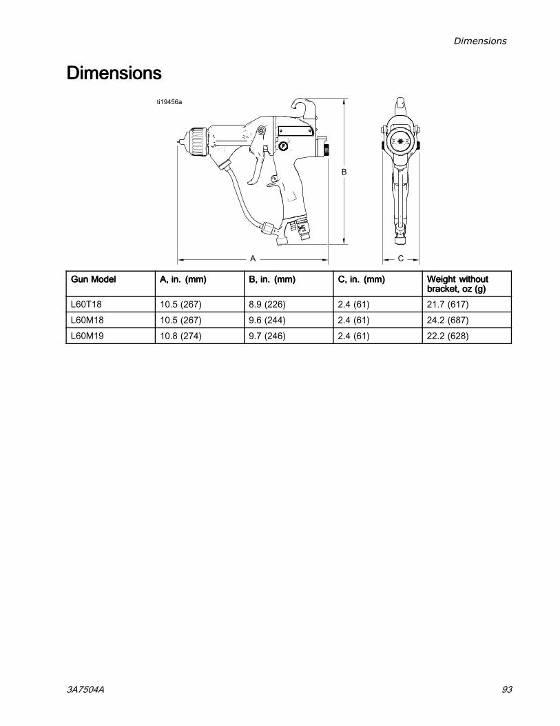
Dimensions
DimensionsDimensionsDimensions
GunGunGun ModelModelModel A,A,A, in.in.in. (mm)(mm)(mm) B,B,B, in.in.in. (mm)(mm)(mm) C,C,C, in.in.in. (mm)(mm)(mm) WeightWeightWeight withoutwithoutwithoutbracket,bracket,bracket, ozozoz (g)(g)(g)
L60T18 10.5 (267) 8.9 (226) 2.4 (61) 21.7 (617)
L60M18 10.5 (267) 9.6 (244) 2.4 (61) 24.2 (687)
L60M19 10.8 (274) 9.7 (246) 2.4 (61) 22.2 (628)
3A7504A 93

Technical Specifications
TechnicalTechnicalTechnical SpecificationsSpecificationsSpecificationsProProPro XpXpXp 606060 WBWBWB GunGunGun
U.S.U.S.U.S. MetricMetricMetricMaximum Working Fluid Pressure 100 psi 0.7 MPa, 7.0 barMaximum Working Air Pressure 100 psi 0.7 MPa, 7.0 barMinimum Air Pressure at Gun Inlet 45 psi 0.32 MPa, 3.2 barGun Air ConsumptionRequired turbine air flow 6 scfm 170 l/minRange of total air flow undernormal spraying conditions
15–20 scfm 425–565 l/min
Maximum Fluid OperatingTemperature
120°F 48°C
Short Circuit Current Output 125 microamperesVoltage Output L60T18: 60 kV
L60M18 and L60M19: 30–60 kVSound Power (measured per ISOStandard 9216)
at 40 psi: 90.4 dB(A)
at 100 psi: 105.4 dB(A)
at 0.28 MPa, 2.8 bar: 90.4 dB(A)
at 0.7 MPa, 7.0 bar: 105.4 dB(A)Sound Pressure (measured 1 mfrom gun)
at 40 psi: 87.0 dB(A)
at 100 psi: 99.0 dB(A)
at 0.28 MPa, 2.8 bar: 87.0 dB(A)
at 0.7 MPa, 7.0 bar: 99.0 dB(A)Air Inlet Fitting 1/4 npsm(m) left-hand threadFluid Inlet Fitting Custom inlet for Graco waterborne fluid hose.Wetted Parts Gun: Stainless Steel, PEEK, UHMWPE, Fluoroelastomer, Acetal,
Nylon, Polyethylene, Tungsten Wire
Waterborne Fluid Hose: FEP
CaliforniaCaliforniaCalifornia PropositionPropositionProposition 656565CALIFORNIACALIFORNIACALIFORNIA RESIDENTSRESIDENTSRESIDENTS
WARNING:WARNING:WARNING: Cancer and reproductive harm — www.P65warnings.ca.gov.
94 3A7504A

Notes
NotesNotesNotes
3A7504A 95
GracoGracoGraco ProProPro XpXpXp WarrantyWarrantyWarranty
Graco warrants all equipment referenced in this document which is manufactured by Graco and bearing its nameto be free from defects in material and workmanship on the date of sale to the original purchaser for use. With theexception of any special, extended, or limited warranty published by Graco, Graco will, for a period of twelve monthsfrom the date of sale, repair or replace any part of the equipment determined by Graco to be defective. However, anydeficiency in the barrel, handle, trigger, hook, internal power supply, and alternator (excluding turbine bearings) will berepaired or replaced for thirty-six months from the date of sale. This warranty applies only when the equipment isinstalled, operated and maintained in accordance with Graco’s written recommendations.
This warranty does not cover, and Graco shall not be liable for general wear and tear, or any malfunction, damageor wear caused by faulty installation, misapplication, abrasion, corrosion, inadequate or improper maintenance,negligence, accident, tampering, or substitution of non-Graco component parts. Nor shall Graco be liable formalfunction, damage or wear caused by the incompatibility of Graco equipment with structures, accessories,equipment or materials not supplied by Graco, or the improper design, manufacture, installation, operation ormaintenance of structures, accessories, equipment or materials not supplied by Graco.
This warranty is conditioned upon the prepaid return of the equipment claimed to be defective to an authorizedGraco distributor for verification of the claimed defect. If the claimed defect is verified, Graco will repair or replacefree of charge any defective parts. The equipment will be returned to the original purchaser transportation prepaid.If inspection of the equipment does not disclose any defect in material or workmanship, repairs will be made at areasonable charge, which charges may include the costs of parts, labor, and transportation.
THISTHISTHIS WARRANTYWARRANTYWARRANTY ISISIS EXCLUSIVE,EXCLUSIVE,EXCLUSIVE, ANDANDAND ISISIS INININ LIEULIEULIEU OFOFOF ANYANYANY OTHEROTHEROTHER WARRANTIES,WARRANTIES,WARRANTIES, EXPRESSEXPRESSEXPRESS OROROR IMPLIED,IMPLIED,IMPLIED,INCLUDINGINCLUDINGINCLUDING BUTBUTBUT NOTNOTNOT LIMITEDLIMITEDLIMITED TOTOTO WARRANTYWARRANTYWARRANTY OFOFOF MERCHANTABILITYMERCHANTABILITYMERCHANTABILITY OROROR WARRANTYWARRANTYWARRANTY OFOFOF FITNESSFITNESSFITNESS FORFORFOR AAAPARTICULARPARTICULARPARTICULAR PURPOSE.PURPOSE.PURPOSE.
Graco’s sole obligation and buyer’s sole remedy for any breach of warranty shall be as set forth above. The buyeragrees that no other remedy (including, but not limited to, incidental or consequential damages for lost profits, lostsales, injury to person or property, or any other incidental or consequential loss) shall be available. Any action forbreach of warranty must be brought within two (2) years of the date of sale.
GRACOGRACOGRACO MAKESMAKESMAKES NONONO WARRANTY,WARRANTY,WARRANTY, ANDANDAND DISCLAIMSDISCLAIMSDISCLAIMS ALLALLALL IMPLIEDIMPLIEDIMPLIED WARRANTIESWARRANTIESWARRANTIES OFOFOF MERCHANTABILITYMERCHANTABILITYMERCHANTABILITY ANDANDANDFITNESSFITNESSFITNESS FORFORFOR AAA PARTICULARPARTICULARPARTICULAR PURPOSE,PURPOSE,PURPOSE, INININ CONNECTIONCONNECTIONCONNECTION WITHWITHWITH ACCESSORIES,ACCESSORIES,ACCESSORIES, EQUIPMENT,EQUIPMENT,EQUIPMENT, MATERIALSMATERIALSMATERIALSOROROR COMPONENTSCOMPONENTSCOMPONENTS SOLDSOLDSOLD BUTBUTBUT NOTNOTNOT MANUFACTUREDMANUFACTUREDMANUFACTURED BYBYBY GRACO.GRACO.GRACO. These items sold, but not manufactured byGraco (such as electric motors, switches, hose, etc.), are subject to the warranty, if any, of their manufacturer. Gracowill provide purchaser with reasonable assistance in making any claim for breach of these warranties.
In no event will Graco be liable for indirect, incidental, special or consequential damages resulting from Gracosupplying equipment hereunder, or the furnishing, performance, or use of any products or other goods sold hereto,whether due to a breach of contract, breach of warranty, the negligence of Graco, or otherwise.
FOR GRACO CANADA CUSTOMERSThe Parties acknowledge that they have required that the present document, as well as all documents, notices andlegal proceedings entered into, given or instituted pursuant hereto or relating directly or indirectly hereto, be drawnup in English. Les parties reconnaissent avoir convenu que la rédaction du présente document sera en Anglais,ainsi que tous documents, avis et procédures judiciaires exécutés, donnés ou intentés, à la suite de ou en rapport,directement ou indirectement, avec les procédures concernées.
GracoGracoGraco InformationInformationInformationFor the latest information about Graco products, visit www.graco.com. For patent information, seewww.graco.com/patents.
ToToTo placeplaceplace ananan order,order,order, contact your Graco Distributor or call to identify the nearest distributor.
Phone:Phone:Phone: 612-623-6921 ororor TollTollToll Free:Free:Free: 1-800-328-0211 Fax:Fax:Fax: 612-378-3505
All written and visual data contained in this document reflects the latest product information available at the time of publication.
Graco reserves the right to make changes at any time without notice.
Original Instructions. This manual contains English, MM 3A7504
GracoGracoGraco Headquarters:Headquarters:Headquarters: Minneapolis
InternationalInternationalInternational Offices:Offices:Offices: Belgium, China, Japan, Korea
GRACOGRACOGRACO INC.INC.INC. ANDANDAND SUBSIDIARIESSUBSIDIARIESSUBSIDIARIES ••• P.O.P.O.P.O. BOXBOXBOX 144114411441 ••• MINNEAPOLIS,MINNEAPOLIS,MINNEAPOLIS, MNMNMN 55440-144155440-144155440-1441 ••• USAUSAUSA
CopyrightCopyrightCopyright 2012,2012,2012, GracoGracoGraco Inc.Inc.Inc. AllAllAll GracoGracoGraco manufacturingmanufacturingmanufacturing locationslocationslocations areareare registeredregisteredregistered tototo ISOISOISO 9001.9001.9001.
www.graco.com
Revision A, March 2020