Embed Size (px)
DESCRIPTION
storage tank
Citation preview
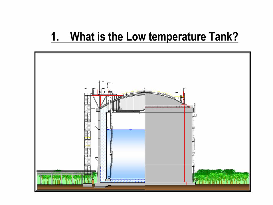
1. What is the Low temperature Tank?
1.CONTAINMENT TYPE PER BS 7777 Part 1 Section 3 - Definitions
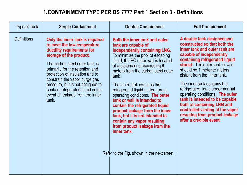
Type of Tank Single Containment Double Containment Full Containment
Definitions Only the inner tank is required to meet the low temperature ductility requirements for storage of the product.
The carbon steel outer tank is primarily for the retention and protection of insulation and to constrain the vapor purge gas pressure, but is not designed to contain refrigerated liquid in the event of leakage from the inner tank.
Both the inner tank and outer tank are capable of independently containing LNG. To minimize the pool of escaping liquid, the PC outer wall is located at a distance not exceeding 6 meters from the carbon steel outer tank.
The inner tank contains the refrigerated liquid under normal operating conditions. The outer tank or wall is intended to contain the refrigerated liquid product leakage from the inner tank, but it is not intended to contain any vapor resulting from product leakage from the inner tank.
A double tank designed and constructed so that both the inner tank and outer tank are capable of independently containing refrigerated liquid stored. The outer tank or wall should be 1 meter to meters distant from the inner tank.
The inner tank contains the refrigerated liquid under normal operating conditions. The outer tank is intended to be capable both of containing LNG and controlled venting of the vapor resulting from product leakage after a credible event.
Refer to the Fig. shown in the next sheet.
1.CONTAINMENT TYPE PER BS 7777 Part 1 Section 3 - Definitions
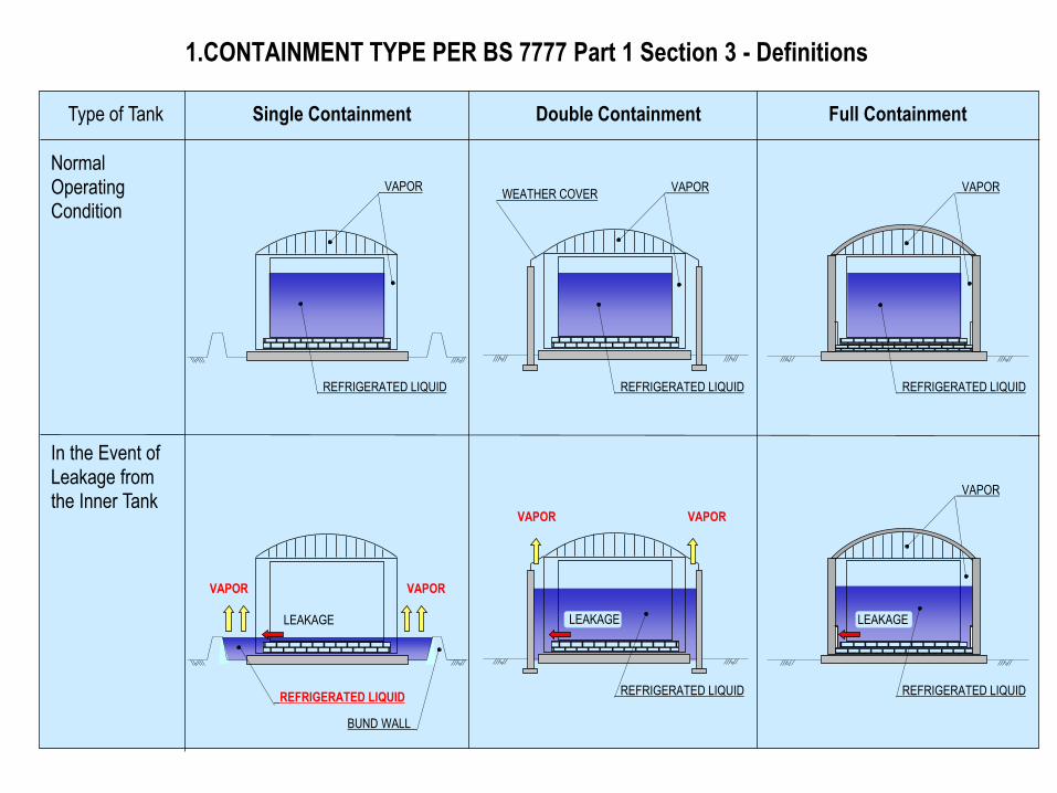
Type of Tank Single Containment Double Containment Full Containment
In the Event of
Leakage from the Inner Tank
Normal Operating Condition
REFRIGERATED LIQUID
VAPOR
REFRIGERATED LIQUID
VAPOR
REFRIGERATED LIQUID
VAPOR VAPOR
BUND WALL
LEAKAGE
REFRIGERATED LIQUID
VAPOR VAPOR
LEAKAGE
REFRIGERATED LIQUID
VAPOR
LEAKAGE
REFRIGERATED LIQUID
VAPOR WEATHER COVER
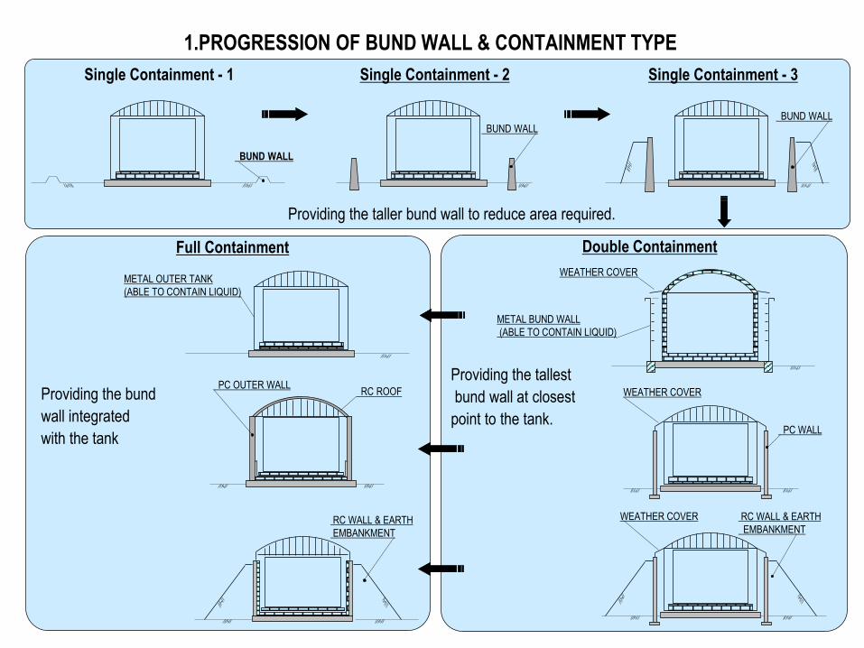
1.PROGRESSION OF BUND WALL & CONTAINMENT TYPE
Single Containment - 3
BUND WALL
Single Containment - 1
BUND WALL
Single Containment - 2
BUND WALL
Providing the taller bund wall to reduce area required.
Providing the tallest
bund wall at closest
point to the tank.
Double Containment
RC WALL & EARTH
EMBANKMENT
WEATHER COVER
WEATHER COVER
PC WALL
METAL BUND WALL
(ABLE TO CONTAIN LIQUID)
WEATHER COVER
Full Containment
RC ROOF PC OUTER WALL
RC WALL & EARTH
EMBANKMENT
Providing the bund
wall integrated
with the tank
METAL OUTER TANK
(ABLE TO CONTAIN LIQUID)
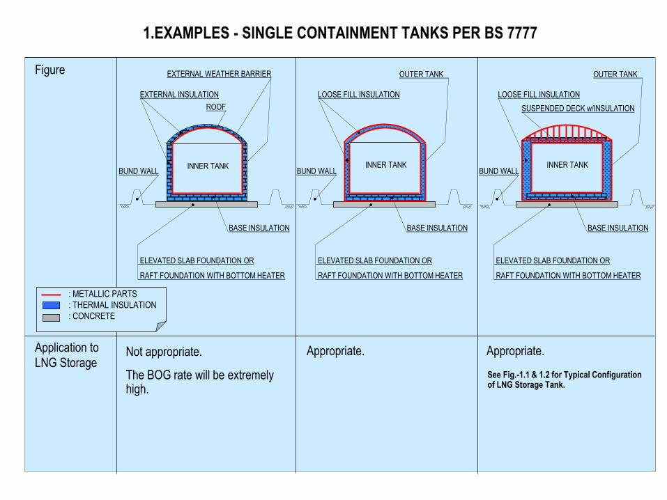
1.EXAMPLES - SINGLE CONTAINMENT TANKS PER BS 7777
Application to
LNG Storage Not appropriate.
The BOG rate will be extremely high.
Appropriate. Appropriate.
See Fig.-1.1 & 1.2 for Typical Configuration of LNG Storage Tank.
Figure
: METALLIC PARTS
: THERMAL INSULATION
: CONCRETE
BUND WALL
ELEVATED SLAB FOUNDATION OR
RAFT FOUNDATION WITH BOTTOM HEATER
BASE INSULATION
EXTERNAL INSULATION
EXTERNAL WEATHER BARRIER
ROOF
BUND WALL
ELEVATED SLAB FOUNDATION OR
RAFT FOUNDATION WITH BOTTOM HEATER
INNER TANK
BASE INSULATION
LOOSE FILL INSULATION
OUTER TANK
BUND WALL
ELEVATED SLAB FOUNDATION OR
RAFT FOUNDATION WITH BOTTOM HEATER
INNER TANK INNER TANK
LOOSE FILL INSULATION
SUSPENDED DECK w/INSULATION
BASE INSULATION
OUTER TANK
INNER TANK
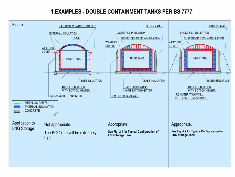
1.EXAMPLES - DOUBLE CONTAINMENT TANKS PER BS 7777
Figure
Application to
LNG Storage Not appropriate.
The BOG rate will be extremely high.
Appropriate. Appropriate.
See Fig.-2.1 for Typical Configuration of LNG Storage Tank.
See Fig.-2.2 for Typical Configuration for LNG Storage Tank.
: METALLIC PARTS
: THERMAL INSULATION
: CONCRETE
BASE INSULATION
EXTERNAL INSULATION
EXTERNAL WEATHER BARRIER
ROOF
RAFT FOUNDATION WITH BOTTOM HEATER
INNER TANK
WEATHER
COVER
METAL OUTER TANK SHELL
LOOSE FILL INSULATION
SUSPENDED DECK w/INSULATION
BASE INSULATION
OUTER TANK
INNER TANK
RAFT FOUNDATION WITH BOTTOM HEATER
PC OUTER TANK WALL
WEATHER
COVER
LOOSE FILL INSULATION
SUSPENDED DECK w/INSULATION
BASE INSULATION
OUTER TANK
INNER TANK
RAFT FOUNDATION WITH BOTTOM HEATER
RC OUTER TANK WALL WITH EARTH EMBANKMENT
WEATHER
COVER
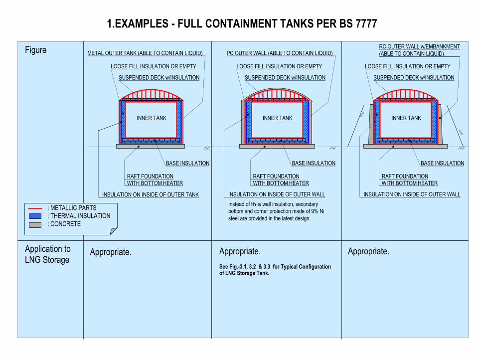
1.EXAMPLES - FULL CONTAINMENT TANKS PER BS 7777
Figure
Application to
LNG Storage Appropriate. Appropriate. Appropriate.
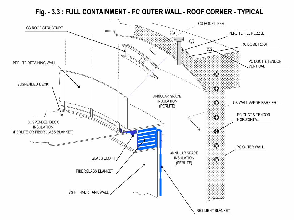
See Fig.-3.1, 3.2 & 3.3 for Typical Configuration of LNG Storage Tank.
SUSPENDED DECK w/INSULATION
BASE INSULATION
INNER TANK
RAFT FOUNDATION WITH BOTTOM HEATER
SUSPENDED DECK w/INSULATION
BASE INSULATION
INNER TANK
RAFT FOUNDATION WITH BOTTOM HEATER
LOOSE FILL INSULATION OR EMPTY
SUSPENDED DECK w/INSULATION
BASE INSULATION
METAL OUTER TANK (ABLE TO CONTAIN LIQUID)
INNER TANK
RAFT FOUNDATION WITH BOTTOM HEATER
INSULATION ON INSIDE OF OUTER TANK
LOOSE FILL INSULATION OR EMPTY
PC OUTER WALL (ABLE TO CONTAIN LIQUID)
INSULATION ON INSIDE OF OUTER WALL
LOOSE FILL INSULATION OR EMPTY
RC OUTER WALL w/EMBANKMENT
(ABLE TO CONTAIN LIQUID)
INSULATION ON INSIDE OF OUTER WALL
Instead of this wall insulation, secondary
bottom and corner protection made of 9% Ni
steel are provided in the latest design.
: METALLIC PARTS
: THERMAL INSULATION
: CONCRETE
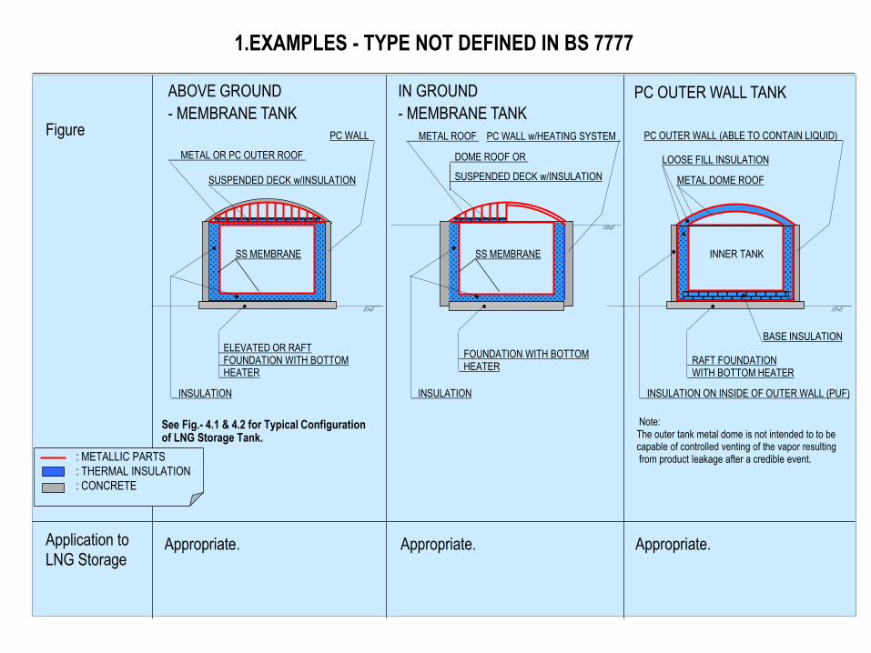
1.EXAMPLES - TYPE NOT DEFINED IN BS 7777
Application to LNG Storage
Appropriate. Appropriate. Appropriate.
Figure
SUSPENDED DECK w/INSULATION
SS MEMBRANE
ELEVATED OR RAFT FOUNDATION WITH BOTTOM HEATER
PC WALL
INSULATION
BASE INSULATION
RAFT FOUNDATION WITH BOTTOM HEATER
INSULATION ON INSIDE OF OUTER WALL (PUF)
See Fig.- 4.1 & 4.2 for Typical Configuration of LNG Storage Tank.
Note: The outer tank metal dome is not intended to to be capable of controlled venting of the vapor resulting from product leakage after a credible event.
METAL OR PC OUTER ROOF
INSULATION
FOUNDATION WITH BOTTOM HEATER
METAL DOME ROOF
INNER TANK
LOOSE FILL INSULATION
PC OUTER WALL (ABLE TO CONTAIN LIQUID)
DOME ROOF OR
SUSPENDED DECK w/INSULATION
SS MEMBRANE
PC WALL w/HEATING SYSTEM METAL ROOF
ABOVE GROUND
- MEMBRANE TANK
IN GROUND
- MEMBRANE TANK
PC OUTER WALL TANK
: METALLIC PARTS
: THERMAL INSULATION
: CONCRETE
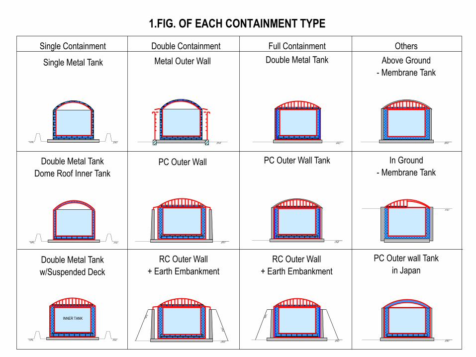
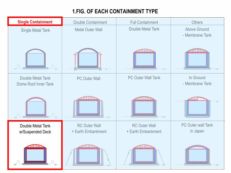
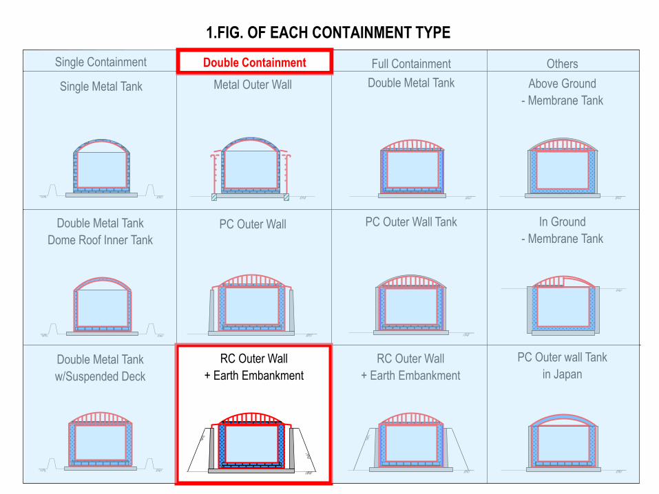
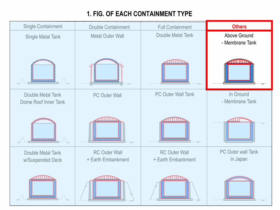
1.FIG. OF EACH CONTAINMENT TYPE
INNER TANK
INNER TANK
Single Containment Double Containment Full Containment Others
Single Metal Tank
Double Metal Tank
Dome Roof Inner Tank
Double Metal Tank
w/Suspended Deck
Metal Outer Wall
PC Outer Wall
RC Outer Wall
+ Earth Embankment
Double Metal Tank
PC Outer Wall Tank
RC Outer Wall
+ Earth Embankment
Above Ground
- Membrane Tank
In Ground
- Membrane Tank
PC Outer wall Tank
in Japan
1.FIG. OF EACH CONTAINMENT TYPE
Single Containment
Double Metal Tank
w/Suspended Deck
Single Metal Tank
INNER TANK
Double Metal Tank
Dome Roof Inner Tank
Double Containment Full Containment Others
Metal Outer Wall
PC Outer Wall
RC Outer Wall
+ Earth Embankment
Double Metal Tank
PC Outer Wall Tank
RC Outer Wall
+ Earth Embankment
Above Ground
- Membrane Tank
In Ground
- Membrane Tank
PC Outer wall Tank
in Japan
Single Containment
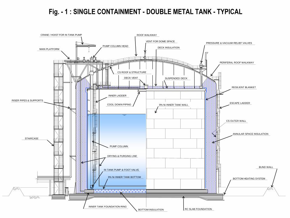
ESCAPE LADDER
RESILIENT BLANKET
RC SLAB FOUNDATION
9% Ni INNER TANK WALL
ANNULAR SPACE INSULATION
CS ROOF & STRUCTURE
SUSPENDED DECK
DECK INSULATION
ROOF WALKWAY
PRESSURE & VACUUM RELIEF VALVES
PERIFERAL ROOF WALKWAY
DECK VENT
BOTTOM HEATING SYSTEM 9% Ni INNER TANK BOTTOM
INNER LADDER
STAIRCASE
MAIN PLATFORM
CRANE / HOIST FOR IN TANK PUMP
PUMP COLUMN HEAD
PUMP COLUMN
IN TANK PUMP & FOOT VALVE
INNER TANK FOUNDATION RING
COOL DOWN PIPING
BOTTOM INSULATION
Fig. - 1 : SINGLE CONTAINMENT - DOUBLE METAL TANK - TYPICAL
DRYING & PURGING LINE
VENT FOR DOME SPACE
RISER PIPES & SUPPORTS
CS OUTER WALL
BUND WALL
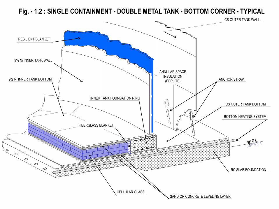
CONCRETE SLAB FOUNDATION Fig. - 1.2 : SINGLE CONTAINMENT - DOUBLE METAL TANK - BOTTOM CORNER - TYPICAL
9% Ni INNER TANK WALL
RESILIENT BLANKET
CS OUTER TANK WALL
INNER TANK FOUNDATION RING
CS OUTER TANK BOTTOM
BOTTOM HEATING SYSTEM
9% Ni INNER TANK BOTTOM
FIBERGLASS BLANKET
ANNULAR SPACE
INSULATION
(PERLITE)
RC SLAB FOUNDATION
SAND OR CONCRETE LEVELING LAYER CELLULAR GLASS
ANCHOR STRAP
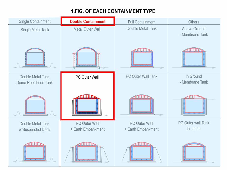
1.FIG. OF EACH CONTAINMENT TYPE
Single Containment
Double Metal Tank
w/Suspended Deck
Single Metal Tank
INNER TANK
Double Metal Tank
Dome Roof Inner Tank
Double Containment Full Containment Others
Metal Outer Wall
PC Outer Wall
RC Outer Wall
+ Earth Embankment
Double Metal Tank
PC Outer Wall Tank
RC Outer Wall
+ Earth Embankment
Above Ground
- Membrane Tank
In Ground
- Membrane Tank
PC Outer wall Tank
in Japan
Double Containment
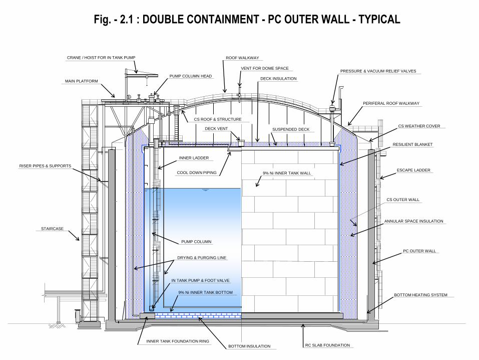
ESCAPE LADDER
RESILIENT BLANKET
RC SLAB FOUNDATION
9% Ni INNER TANK WALL
ANNULAR SPACE INSULATION
CS ROOF & STRUCTURE
SUSPENDED DECK
DECK INSULATION
ROOF WALKWAY
PRESSURE & VACUUM RELIEF VALVES
PERIFERAL ROOF WALKWAY
DECK VENT
BOTTOM HEATING SYSTEM 9% Ni INNER TANK BOTTOM
INNER LADDER
STAIRCASE
MAIN PLATFORM
CRANE / HOIST FOR IN TANK PUMP
PUMP COLUMN HEAD
PUMP COLUMN
IN TANK PUMP & FOOT VALVE
INNER TANK FOUNDATION RING
COOL DOWN PIPING
BOTTOM INSULATION
Fig. - 2.1 : DOUBLE CONTAINMENT - PC OUTER WALL - TYPICAL
DRYING & PURGING LINE
VENT FOR DOME SPACE
RISER PIPES & SUPPORTS
CS OUTER WALL
CS WEATHER COVER
PC OUTER WALL
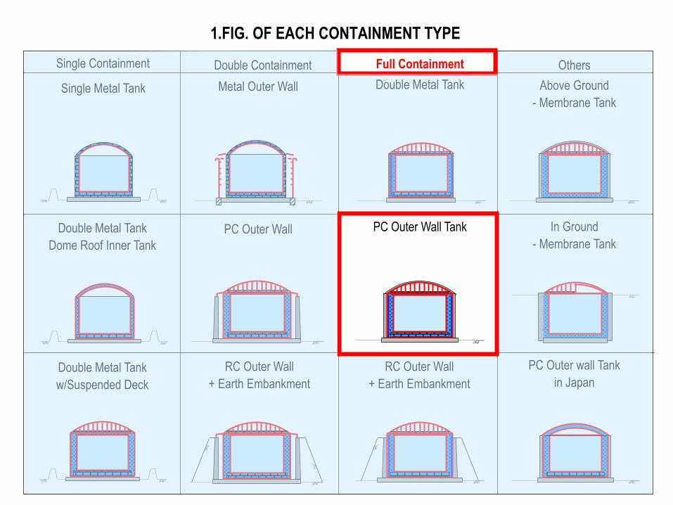
1.FIG. OF EACH CONTAINMENT TYPE
Single Containment
Double Metal Tank
w/Suspended Deck
Single Metal Tank
INNER TANK
Double Metal Tank
Dome Roof Inner Tank
Double Containment Full Containment Others
Metal Outer Wall
PC Outer Wall
RC Outer Wall
+ Earth Embankment
Double Metal Tank
PC Outer Wall Tank
RC Outer Wall
+ Earth Embankment
Above Ground
- Membrane Tank
In Ground
- Membrane Tank
PC Outer wall Tank
in Japan
Double Containment
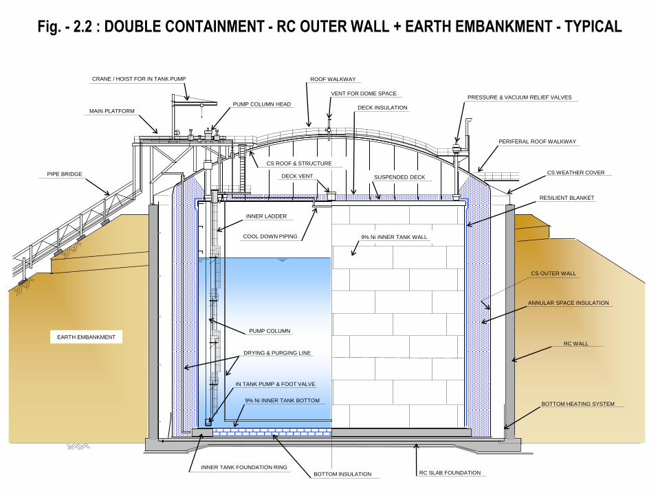
RESILIENT BLANKET
RC SLAB FOUNDATION
9% Ni INNER TANK WALL
ANNULAR SPACE INSULATION
CS ROOF & STRUCTURE
SUSPENDED DECK
DECK INSULATION
ROOF WALKWAY
PRESSURE & VACUUM RELIEF VALVES
PERIFERAL ROOF WALKWAY
DECK VENT
BOTTOM HEATING SYSTEM 9% Ni INNER TANK BOTTOM
INNER LADDER
MAIN PLATFORM
CRANE / HOIST FOR IN TANK PUMP
PUMP COLUMN HEAD
PUMP COLUMN
IN TANK PUMP & FOOT VALVE
INNER TANK FOUNDATION RING
COOL DOWN PIPING
BOTTOM INSULATION
Fig. - 2.2 : DOUBLE CONTAINMENT - RC OUTER WALL + EARTH EMBANKMENT - TYPICAL
DRYING & PURGING LINE
VENT FOR DOME SPACE
CS OUTER WALL
CS WEATHER COVER
RC WALL
EARTH EMBANKMENT
PIPE BRIDGE
1.FIG. OF EACH CONTAINMENT TYPE
Single Containment
Double Metal Tank
w/Suspended Deck
Single Metal Tank
INNER TANK
Double Metal Tank
Dome Roof Inner Tank
Double Containment Full Containment Others
Metal Outer Wall
PC Outer Wall
RC Outer Wall
+ Earth Embankment
Double Metal Tank
PC Outer Wall Tank
RC Outer Wall
+ Earth Embankment
Above Ground
- Membrane Tank
In Ground
- Membrane Tank
PC Outer wall Tank
in Japan
Full Containment
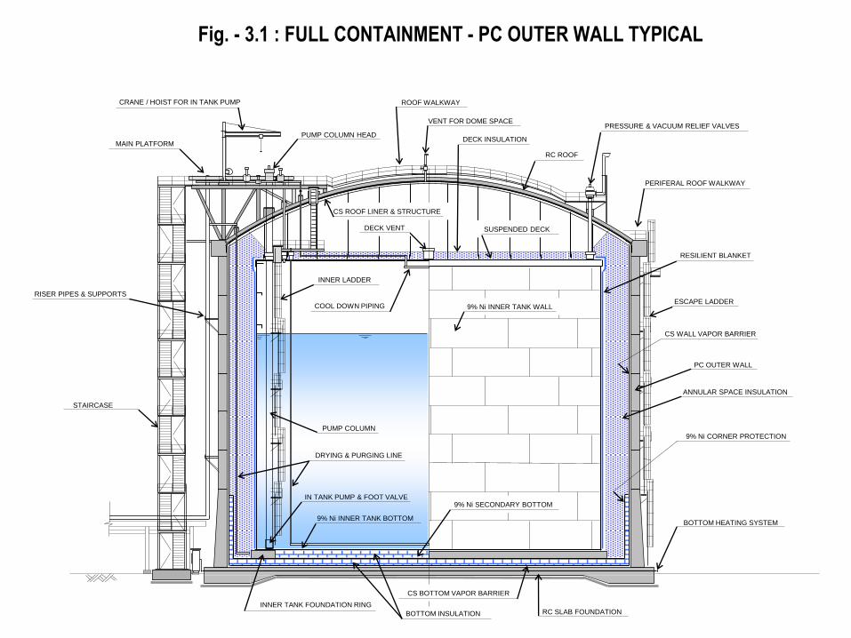
ESCAPE LADDER
RESILIENT BLANKET
RC SLAB FOUNDATION
9% Ni INNER TANK WALL
ANNULAR SPACE INSULATION
RC ROOF
CS ROOF LINER & STRUCTURE
SUSPENDED DECK
DECK INSULATION
ROOF WALKWAY
PRESSURE & VACUUM RELIEF VALVES
PERIFERAL ROOF WALKWAY
DECK VENT
BOTTOM HEATING SYSTEM 9% Ni INNER TANK BOTTOM
INNER LADDER
STAIRCASE
MAIN PLATFORM
CRANE / HOIST FOR IN TANK PUMP
PUMP COLUMN HEAD
PUMP COLUMN
IN TANK PUMP & FOOT VALVE 9% Ni SECONDARY BOTTOM
9% Ni CORNER PROTECTION
CS WALL VAPOR BARRIER
INNER TANK FOUNDATION RING
CS BOTTOM VAPOR BARRIER
COOL DOWN PIPING
BOTTOM INSULATION
Fig. - 3.1 : FULL CONTAINMENT - PC OUTER WALL TYPICAL
DRYING & PURGING LINE
VENT FOR DOME SPACE
RISER PIPES & SUPPORTS
PC OUTER WALL
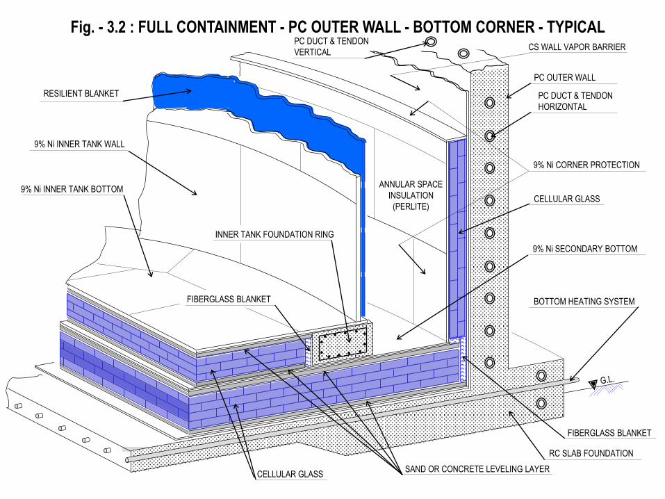
CELLULAR GLASS
CONCRETE SLAB FOUNDATION Fig. - 3.2 : FULL CONTAINMENT - PC OUTER WALL - BOTTOM CORNER - TYPICAL
PC OUTER WALL
9% Ni CORNER PROTECTION
9% Ni INNER TANK WALL
RESILIENT BLANKET
ANNULAR SPACE
INSULATION
(PERLITE)
CS WALL VAPOR BARRIER
RC SLAB FOUNDATION
INNER TANK FOUNDATION RING
9% Ni SECONDARY BOTTOM
BOTTOM HEATING SYSTEM
SAND OR CONCRETE LEVELING LAYER CELLULAR GLASS
9% Ni INNER TANK BOTTOM
FIBERGLASS BLANKET
FIBERGLASS BLANKET
PC DUCT & TENDON
HORIZONTAL
PC DUCT & TENDON
VERTICAL
CS WALL VAPOR BARRIER
CONCRETE SLAB FOUNDATION Fig. - 3.3 : FULL CONTAINMENT - PC OUTER WALL - ROOF CORNER - TYPICAL
RC DOME ROOF
CS ROOF LINER
GLASS CLOTH
PERLITE RETAINING WALL
SUSPENDED DECK
INSULATION
(PERLITE OR FIBERGLASS BLANKET)
ANNULAR SPACE
INSULATION
(PERLITE)
PC OUTER WALL
PERLITE FILL NOZZLE
SUSPENDED DECK
ANNULAR SPACE
INSULATION
(PERLITE)
RESILIENT BLANKET
9% NI INNER TANK WALL
CS ROOF STRUCTURE
FIBERGLASS BLANKET
PC DUCT & TENDON
VERTICAL
PC DUCT & TENDON
HORIZONTAL
1. FIG. OF EACH CONTAINMENT TYPE
Single Containment
Double Metal Tank
w/Suspended Deck
Single Metal Tank
INNER TANK
Double Metal Tank
Dome Roof Inner Tank
Double Containment Full Containment Others
Metal Outer Wall
PC Outer Wall
RC Outer Wall
+ Earth Embankment
Double Metal Tank
PC Outer Wall Tank
RC Outer Wall
+ Earth Embankment
Above Ground
- Membrane Tank
In Ground
- Membrane Tank
PC Outer wall Tank
in Japan
Others
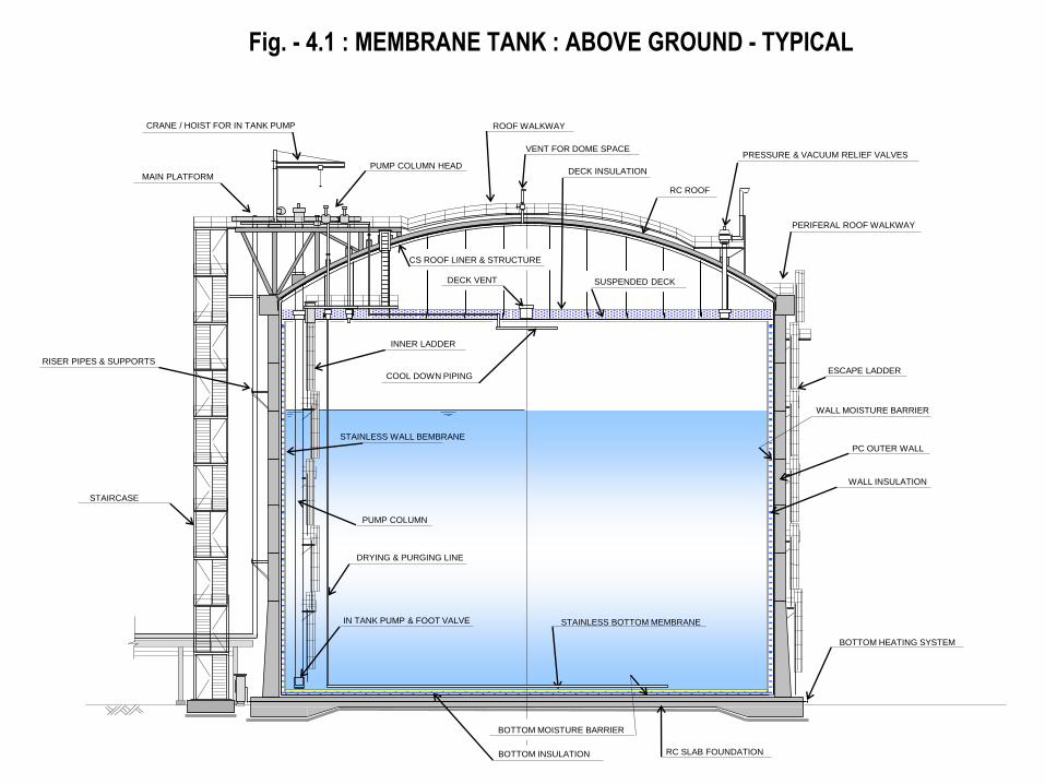
ESCAPE LADDER
RC SLAB FOUNDATION
WALL INSULATION
RC ROOF
CS ROOF LINER & STRUCTURE
SUSPENDED DECK
DECK INSULATION
ROOF WALKWAY
PRESSURE & VACUUM RELIEF VALVES
PERIFERAL ROOF WALKWAY
DECK VENT
BOTTOM HEATING SYSTEM
INNER LADDER
STAIRCASE
MAIN PLATFORM
CRANE / HOIST FOR IN TANK PUMP
PUMP COLUMN HEAD
PUMP COLUMN
IN TANK PUMP & FOOT VALVE STAINLESS BOTTOM MEMBRANE
WALL MOISTURE BARRIER
BOTTOM MOISTURE BARRIER
COOL DOWN PIPING
BOTTOM INSULATION
Fig. - 4.1 : MEMBRANE TANK : ABOVE GROUND - TYPICAL
DRYING & PURGING LINE
VENT FOR DOME SPACE
RISER PIPES & SUPPORTS
PC OUTER WALL
STAINLESS WALL BEMBRANE
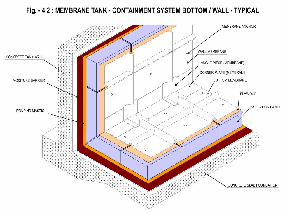
Fig. - 4.2 : MEMBRANE TANK - CONTAINMENT SYSTEM BOTTOM / WALL - TYPICAL
ANGLE PIECE (MEMBRANE)
CORNER PLATE (MEMBRANE)
WALL MEMBRANE
BOTTOM MEMBRANE
PLYWOOD
INSULATION PANEL
CONCRETE TANK WALL
MOISTURE BARRIER
BONDIND MASTIC
CONCRETE SLAB FOUNDATION
MEMBRANE ANCHOR
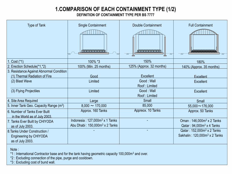
1.COMPARISON OF EACH CONTAINMENT TYPE (1/2) DEFINITION OF CONTAINMENT TYPE PER BS 7777
Type of Tank Single Containment Double Containment Full Containment
1. Cost (*1)
2. Erection Schedule(*1,*2)
3. Resistance Against Abnormal Condition
(1) Thermal Radiation of Fire
(2) Blast Wave
(3) Flying Projectiles
4. Site Area Required
5. Inner Tank Geo. Capacity Range (m3)
100% *3
100% (Min. 25 months)
Good
Limited
Limited
Large
8,000 ~ 170,000
Approx. 160 Tanks
Indonesia : 127,000m3 x 1 Tanks
Abu Dhabi : 150,000m3 x 2 Tanks
-
150%
125% (Approx. 32 months)
Excellent
Good : Wall
Roof : Limited
Good : Wall
Roof : Limited
Small
85,000
Appreox. 10 Tanks
-
-
180%
140% (Approx. 35 months)
Excellent
Excellent
Excellent
Small
55,000~176,000
Approx. 50 Tanks
Oman : 146,000m3 x 2 Tanks
Qatar : 94,000m3 x 4 Tanks
Qatar : 152,000m3 x 2 Tanks
Sakhalin : 120,000m3 x 2 Tanks
Note : *1 : International Contractor base and for the tank having geometric capacity 100,000m3 and over. *2 : Excluding connection of the pipe, purge and cooldown. *3 : Excluding cost of bund wall.
6. Number of Tanks Ever Built
in the World as of July 2003.
7. Tanks Ever Built by CHIYODA
as of July 2003.
8.Tanks Under Construction /
Engineering by CHIYODA
as of July 2003.
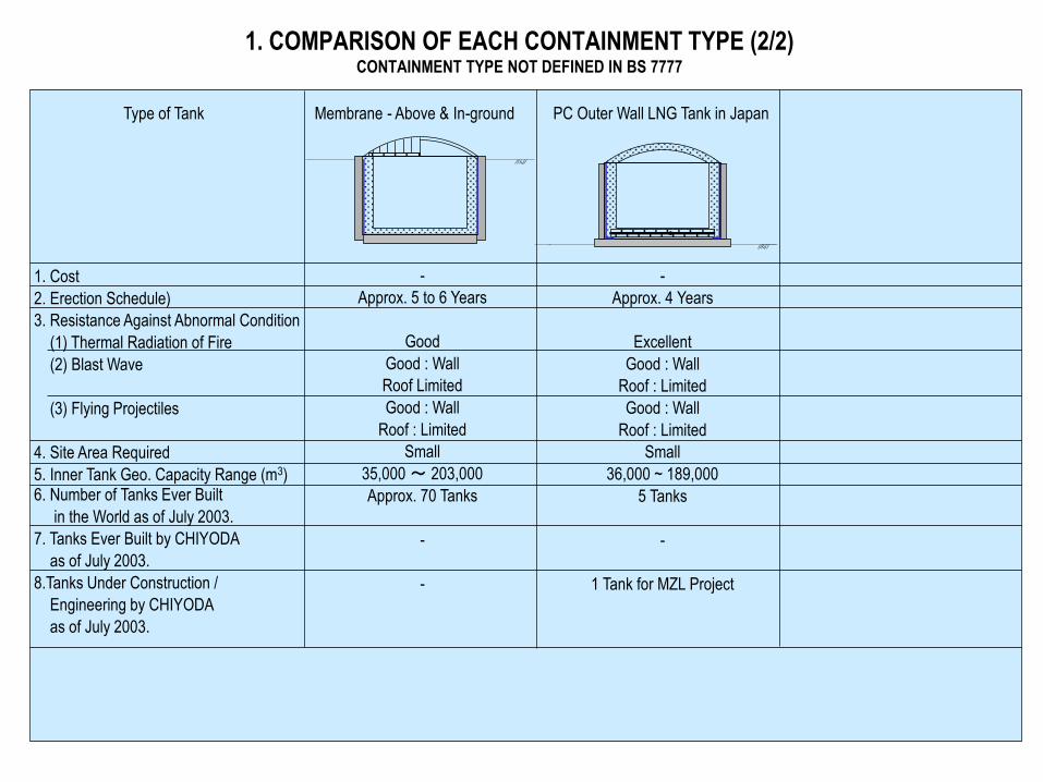
1. COMPARISON OF EACH CONTAINMENT TYPE (2/2) CONTAINMENT TYPE NOT DEFINED IN BS 7777
Type of Tank Membrane - Above & In-ground PC Outer Wall LNG Tank in Japan
1. Cost
2. Erection Schedule)
3. Resistance Against Abnormal Condition
(1) Thermal Radiation of Fire
(2) Blast Wave
(3) Flying Projectiles
4. Site Area Required
5. Inner Tank Geo. Capacity Range (m3)
-
Approx. 5 to 6 Years
Good
Good : Wall
Roof Limited
Good : Wall
Roof : Limited
Small
35,000 ~ 203,000
Approx. 70 Tanks
-
-
-
Approx. 4 Years
Excellent
Good : Wall
Roof : Limited
Good : Wall
Roof : Limited
Small
36,000 ~ 189,000
5 Tanks
-
1 Tank for MZL Project
6. Number of Tanks Ever Built
in the World as of July 2003.
7. Tanks Ever Built by CHIYODA
as of July 2003.
8.Tanks Under Construction /
Engineering by CHIYODA
as of July 2003.
5. MATERIAL SELECTION FOR THE LNG CONTAINER
The material for the LNG container for the large capacity of LNG storage is 9% Ni steel in consideration of the design of -161 ~ -168 oC of the design temperature of LNG as shown in the following sheet “TEMPERATURE RANGE FOR MATERIAL OF CRYOGENIC STORAGE TANKS”. In principle, stainless steel type 304 is used for the tank having small capacity and in case that the use of 9% Ni steel is not economical. The stainless steel type 304 is also used for the membrane of in-ground and above ground tank.
6. TANK SIZING (1/6)
4. TOP DEADWOOD
1. G
EO
ME
TR
IC C
AP
AC
ITY
2. N
ET
WO
RK
ING
CA
PA
CIT
Y
5. BOTTOM DEAD WOOD
3. S
TO
RA
GE
CA
PA
CIT
Y
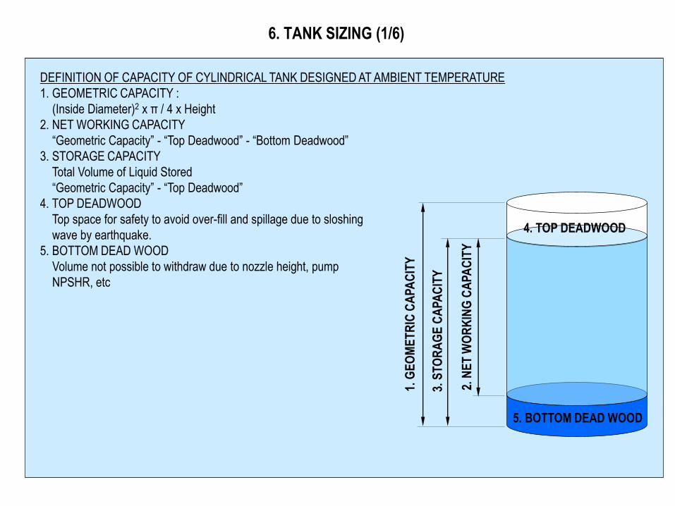
DEFINITION OF CAPACITY OF CYLINDRICAL TANK DESIGNED AT AMBIENT TEMPERATURE
1. GEOMETRIC CAPACITY :
(Inside Diameter)2 x π / 4 x Height
2. NET WORKING CAPACITY
“Geometric Capacity” - “Top Deadwood” - “Bottom Deadwood”
3. STORAGE CAPACITY
Total Volume of Liquid Stored
“Geometric Capacity” - “Top Deadwood”
4. TOP DEADWOOD
Top space for safety to avoid over-fill and spillage due to sloshing
wave by earthquake.
5. BOTTOM DEAD WOOD
Volume not possible to withdraw due to nozzle height, pump
NPSHR, etc
6. TANK SIZING (2/6)
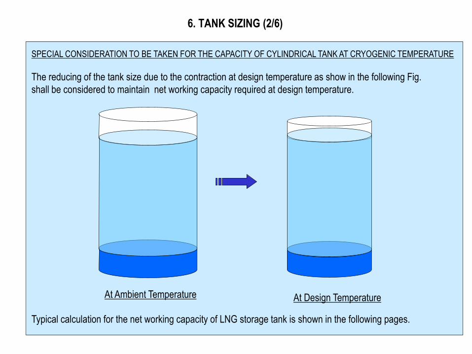
SPECIAL CONSIDERATION TO BE TAKEN FOR THE CAPACITY OF CYLINDRICAL TANK AT CRYOGENIC TEMPERATURE
The reducing of the tank size due to the contraction at design temperature as show in the following Fig.
shall be considered to maintain net working capacity required at design temperature.
At Ambient Temperature
Typical calculation for the net working capacity of LNG storage tank is shown in the following pages.
At Design Temperature
6. TANK SIZING (3/6)
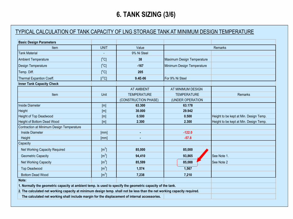
TYPICAL CALCULATION OF TANK CAPACITY OF LNG STORAGE TANK AT MINIMUM DESIGN TEMPERATURE
Basic Design Parameters
Item UNIT Value
Tank Material - 9% Ni Steel
Ambient Temperature [oC] 38 Maximum Design Temperature
Design Temperature [oC] -167 Minimum Design Temperature
Temp. Diff. [oC] 205
Thermal Expantion Coeff. [/oC] 9.4E-06 For 9% Ni Steel
Inner Tank Capacity Check
AT AMBIENT AT MINIMUM DESIGN
Item Unit TEMPERATURE TEMPERATURE Remarks
(CONSTRUCTION PHASE) (UNDER OPERATION
Inside Diameter [m] 63.300 63.178
Height [m] 30.000 29.942
Height of Top Deadwood [m] 0.500 0.500 Height to be kept at Min. Design Temp.
Height of Bottom Dead Wood [m] 2.300 2.300 Height to be kept at Min. Design Temp.
Contraction at Minimum Design Temperature
Inside Diameter [mm] - -122.0
Height [mm] - -57.8
Capacity
Net Working Capacity Required [m3] 85,000 85,000
Geometric Capacity [m3] 94,410 93,865 See Note 1.
Net Working Capacity [m3] 85,599 85,088 See Note 2
Top Deadwood [m3] 1,574 1,567
Bottom Dead Wood [m3] 7,238 7,210
Note:
1. Normally the geometric capacity at ambient temp. is used to specify the geometric capacity of the tank.
2. The calculated net working capacity at minimum design temp. shall not be less than the net working capacity required.
The calculated net working shall include margin for the displacement of internal accessories.
Remarks
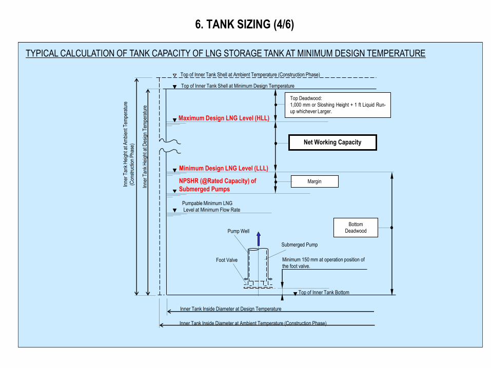
6. TANK SIZING (4/6)
NPSHR (@Rated Capacity) of
Submerged Pumps
Margin
Pumpable Minimum LNG
Level at Minimum Flow Rate
Top of Inner Tank Shell at Minimum Design Temperature
Maximum Design LNG Level (HLL)
Minimum Design LNG Level (LLL)
Net Working Capacity
Top Deadwood:
1,000 mm or Sloshing Height + 1 ft Liquid Run-
up whichever Larger.
Top of Inner Tank Shell at Ambient Temperature (Construction Phase)
Bottom
Deadwood
Minimum 150 mm at operation position of
the foot valve.
Top of Inner Tank Bottom
Pump Well
Foot Valve
Submerged Pump
Inner Tank Inside Diameter at Design Temperature
Inner Tank Inside Diameter at Ambient Temperature (Construction Phase)
Inne
r T
ank
Hei
ght a
t Des
ign
Tem
pera
ture
Inne
r T
ank
Hei
ght a
t Am
bien
t Tem
pera
ture
(C
onst
ruct
ion
Pha
se)
TYPICAL CALCULATION OF TANK CAPACITY OF LNG STORAGE TANK AT MINIMUM DESIGN TEMPERATURE
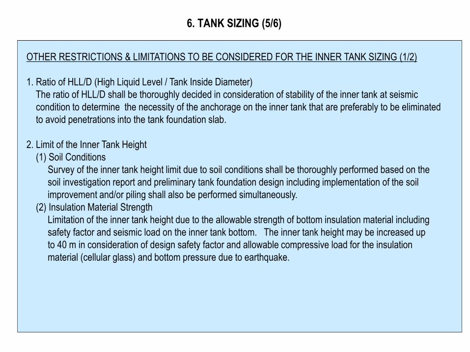
6. TANK SIZING (5/6)
OTHER RESTRICTIONS & LIMITATIONS TO BE CONSIDERED FOR THE INNER TANK SIZING (1/2)
1. Ratio of HLL/D (High Liquid Level / Tank Inside Diameter)
The ratio of HLL/D shall be thoroughly decided in consideration of stability of the inner tank at seismic
condition to determine the necessity of the anchorage on the inner tank that are preferably to be eliminated
to avoid penetrations into the tank foundation slab.
2. Limit of the Inner Tank Height
(1) Soil Conditions
Survey of the inner tank height limit due to soil conditions shall be thoroughly performed based on the
soil investigation report and preliminary tank foundation design including implementation of the soil
improvement and/or piling shall also be performed simultaneously.
(2) Insulation Material Strength
Limitation of the inner tank height due to the allowable strength of bottom insulation material including
safety factor and seismic load on the inner tank bottom. The inner tank height may be increased up
to 40 m in consideration of design safety factor and allowable compressive load for the insulation
material (cellular glass) and bottom pressure due to earthquake.
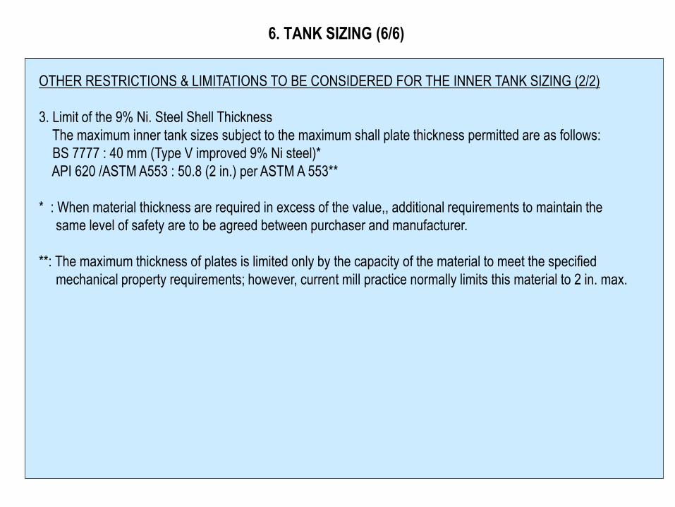
6. TANK SIZING (6/6)
OTHER RESTRICTIONS & LIMITATIONS TO BE CONSIDERED FOR THE INNER TANK SIZING (2/2)
3. Limit of the 9% Ni. Steel Shell Thickness
The maximum inner tank sizes subject to the maximum shall plate thickness permitted are as follows:
BS 7777 : 40 mm (Type V improved 9% Ni steel)*
API 620 /ASTM A553 : 50.8 (2 in.) per ASTM A 553**
* : When material thickness are required in excess of the value,, additional requirements to maintain the
same level of safety are to be agreed between purchaser and manufacturer.
**: The maximum thickness of plates is limited only by the capacity of the material to meet the specified
mechanical property requirements; however, current mill practice normally limits this material to 2 in. max.
Rev.
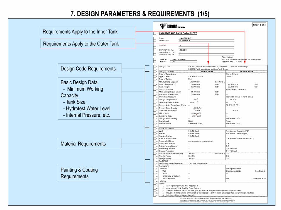
LNG STORAGE TANK DATA SHEET
Owner : A COMPANY
Project Title : X PROJECT
Location : -
CHIYODA Job No. : XXXXXX
Consortium Doc. No. :
CHIYODA Doc. No. :
Abbreviation :
Tank No. : T-0001, & T-0002 TBD = To be determined/verified by Subcontractor
Service : LNG Required Nos. : 2 tanks
1. Design Code API STD 620 9TH ED ADDENDUM 3 , APPENDIX Q for Inner Tank Design
2. BS 7777 Part 3 as guidance for Outer Tank Design
3. Design Condition INNER TANK OUTER TANK
4. Type of Foundation --- Stone Column
5. Type of Roof Suspended Deck Dome
6. Type of Bottom Flat ---
7. Min. Working Capacity 140,000 m3 See Note 1. ---
8. Tank Diameter (I.D) 76,000 mm TBD 78,000 mm TBD
9. Tank Height 35,300 mm TBD 39,000 mm TBD
10. Design Pressure --- +290 mbarg / -5 mbarg
11. Max .Design Liquid Level 34,700 mm TBD ---
12. Hydrotest Water Level 21,000 mm TBD ---
13. Operating Pressure --- From +80 mbarg to +240 mbarg
14. Design Temperature -165 0C 38.5 0C
15. Operating Temperature (Later) 0C --- 0C
16. Design Amb. Temp.(Max./Min.) --- 38.5 0C / 6 0C
17. Design Spec. Gravity 483 kg/m3 ---
18. Corrosion Allowance 0 mm 0 mm
19. Filling Rate 11,500 m3/h ---
20. Emptying Rate 1,707 m3/h ---
21. Design Wind Velocity --- See sheet 2 of 4.
22. Snow Load None None
23. Seismic Load See sheet 2 of 4. See sheet 2 of 4.
24.
25. TANK MATERIAL
26. Wall 9 % Ni Steel Prestressed Concrete (PC)
27. Bottom 9 % Ni Steel Reinforced Concrete (RC)
28. Annular Bottom 9 % Ni Steel ---
29. Roof Plate/Structure --- C.S + Reinforced Concrete (RC)
30. Suspended Deck Aluminum Alloy or equivalent. ---
31. Wall Vapor Barrier --- C.S
32. Bottom Vapor Barrier --- C.S
33. Secondary Bottom --- 9 % Ni Steel
34. Corner Protection --- 9 % Ni Steel
35. Nozzle Neck/Internal Piping 304 SS See Note 2. CS
36. Nozzle Flange 304 SS CS
37. Flange/Bolting 304 SS CS
38. PAINTING
39. Temporary Rust Prevention Yes. See Specification.
40. Permanent
41. External See Specification.
42. Wall --- Bituminous coats See Note 5.
43. Roof --- ---
44. Underside of Bottom --- ---
45. Appurtenances --- Yes See Note 3 & 4.
46. Internal --- ---
47. Notes :
48. 1. At design temperature. See Appendix-3.
49. 2. Alternatively 9% Ni Steel for Pump Columns.
50. 3. Stainless steel bolt and nut such as type 304 and 316 except those of type 316L shall be coated.
51. 4. Including metallic surface for materials of stainless steel, carbon steel, galvanized steel except insulated surface.
52. 5. Side face of buried bottom slab only.
Sheet 1 of 4
ALL RIGHTS RESERVED. THIS DOCUMENT AND ANY DATA AND INFORMATION CONTAINED
THEREIN ARE CONFIDENTIAL AND THE PROPERTY OF CHIYODA CORPORATION (CHIYODA) AND
THE COPYRIGHT THEREIN IS VESTED IN CHIYODA. NO PART OF THIS DOCUMENT, DATA, OR
INFORMATION SHALL BE DISCLOSED TO OTHERS OR REPRODUCED IN ANY MANNER OR USED
FOR ANY PURPOSE WHATSOEVER, EXCEPT WITH THE PRIOR WRITTEN PERMISSION OF CHIYODA.
7. DESIGN PARAMETERS & REQUIREMENTS (1/5)
Requirements Apply to the Inner Tank
Requirements Apply to the Outer Tank
Design Code Requirements
Basic Design Data
- Minimum Working
Capacity
- Tank Size
- Hydrotest Water Level
- Internal Pressure, etc.
Material Requirements
Painting & Coating
Requirements

7. DESIGN PARAMETERS & REQUIREMENTS (2/5)
Seismic Design Condition
Wind Velocity & Pressure
Design Against Flying Object
Design of Spill Protection
Design Against Heat Radiation
Design Against Blast Wave
OBE : Operating Basis Earthquake
SSE : Safety Shutdown Earthquake
See next sheet for detail per NFPA 59A.
7. DESIGN PARAMETERS & REQUIREMENTS (3/5)
OBE ( Operating Basis Earthquake ) and SSE (Safety Shutdown Earthquake) per NFPA 59A
OBE (Operating Basis Earthquake):
The LNG container shall be designed to remain operable during and after an OBE.
SSE (Safety Shutdown Earthquake):
Similarly, the design shall be such that during and after an SSE there shall be no loss of containment
capability, and it shall be possible to isolate and maintain the LNG container.
After the SSE event, the container shall be emptied and inspected prior to resumption of container-
filling operation
7. DESIGN PARAMETERS & REQUIREMENTS (4/5)
Pump Column Design Data
BOG Requirements
BOG Performance Test
Requirements
Rev.
LNG STORAGE TANK DATA SHEET
Owner : A COMPANY
Project Title : X PROJECT
Location : -
CTCI Job No.
CHIYODA Job No. : XXXXXX
Consortium Doc. No. :
CHIYODA Doc. No. :
Abbreviation :
Tank No. : T-0001, & T-0002 TBD = To be determined/verified by Subcontractor
Service : LNG Required Nos. : 2 tanks
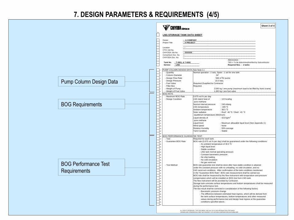
1. PUMP COLUMN DESIGN DATA (See Note 1.)
2. - Quantity Normal operation : 2 sets, Spare : 1 set for one tank
3. - Column Diameter 34"
4. - Design Flow Rate 569 m3/hr pump
5. - Design Pressure 15.0 barg
6. - Foot Valve Required (Supplied by Contractor)
7. - Filter Box Required.
8. - Weight of Pump 2,500 kg / one pump (maximum load to be lifted by hoist /crane)
9. - Weight of Foot Valve 1,300 kg / one foot valve
10. BOG RATE
11. - Maximum BOG Rate 0.075 vol.% per day
12. - Design Condition LNG latent heat of : 122 kcal/kg
13. pure methane
14. Normal Internal pressure : 240 mbarg
15. LNG temperature : -165 ℃
16. Ambient temperature : 38.5 ℃
17. Solar radiation : Roof : 48 ℃ / Shell : 43 ℃
18. equilibrium temperature (Minimum)
19. Liquid density of : 423 kg/m3
20. pure methane
21. Liquid level : Maximum allowable liquid level (See Appendix-3.)
22. Wind speed : None
23. Relative Humidity : 93% average
24. Tank Condition : Stable
25.
26. BOG PERFORMANCE GUARANTEE TEST
27. - Test Required for each tank.
28. - Guarantee BOG Rate BOG rate (0.075 vol.% per day) shall be guaranteed under the following conditions:
29. - An ambient temperature of 30.0 ℃
30. - High liquid level
31. - Stable condition
32. - LNG tank normal operating pressure
33. - Constant barometric pressure
34. - No ship loading
35. - No cold circulation
36. - No gas send-out
37. - Test Method BOG rate guarantee test shall be done after heat stable condition is attained
38. under the constant pressure with no unloading, no cold circulation, and no
39. LNG send-out conditions. After confirmation of the tank conditions mentioned
40. in the "Guarantee BOG Rate", BOG rate measurement shall be carried out.
41. BOG rate shall be measured by the flow instrument with temperature and pressure
42. compensation which will be installed on BOG line from LNG tank.
44. The flow instrument will be provided by Contractor.
45. Storage tank concrete surface temperatures and bottom temperatures shall be measured
46. during the performance test.
47. The test result shall be corrected in consideration of the following factors:
48. - Barometric pressure change
49. - The difference between estimated heat ingress, which will be derived from
50. the tank surface temperatures, bottom temperatures and other measured
51. values during performance test and design heat ingress at the guarantee
52. conditions specified above.
53.
Sheet 3 of 4
ALL RIGHTS RESERVED. THIS DOCUMENT AND ANY DATA AND INFORMATION CONTAINED
THEREIN ARE CONFIDENTIAL AND THE PROPERTY OF CHIYODA CORPORATION (CHIYODA) AND
THE COPYRIGHT THEREIN IS VESTED IN CHIYODA. NO PART OF THIS DOCUMENT, DATA, OR
INFORMATION SHALL BE DISCLOSED TO OTHERS OR REPRODUCED IN ANY MANNER OR USED
FOR ANY PURPOSE WHATSOEVER, EXCEPT WITH THE PRIOR WRITTEN PERMISSION OF CHIYODA.
7. DESIGN PARAMETERS & REQUIREMENTS (5/5)
Tank Appurtenances
Rev.
LNG STORAGE TANK DATA SHEET
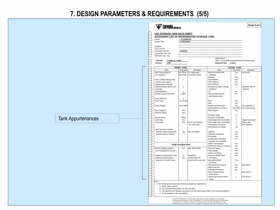
ACCESSORY LIST OF REFRIGERATED STORAGE TANK Owner : A COMPANY
Project Title : X PROJECT
Location : -
CTCI Job No.
CHIYODA Job No. : XXXXXX
Consortium Doc. No. :
CHIYODA Doc. No. :
Abbreviation :
Tank No. : T-0001, & T-0002 TBD = To be determined/verified by Subcontractor
Service : LNG Required Nos. : 2 tanks
1.
2. Item Q'ty-Size Remarks Item Q'ty-Size Remarks
3. Skin Temp Detector per P&ID For shell plate Roof Circumferential All around
4. for cooldown per P&ID For bottom plate Walkway
5. Stairway
6. Inner Ladder along pump 1 Top Platform
7. column with cage & PSV Platform
8. intermediate landings VRV Platform
9. Platform/ladder below roof 2 Emergency ladder w/cage Opposite side of
10. manway & platform stairway
11. Deck Walkway 1 Lift
12. Annular Space Monorail (TBD) External Monorail for
13. Wall Maintenance
14. Deck Manhole 2
15. Deck Vent Yes (TBD) PRV
16. VRV
17. Deck Support Yes (TBD) Nozzle and Manholes Per Appendix-2.
18. Monorail/Hoist or Crane For intank pump.
19. Pipe Supports Yes Pipe Support
20. Internal Piping Yes
21. Pressure Gage
22. Anchor Strap (TBD) Pressure Transmitter
23. Earth lugs Yes Tank Gage with Transmitter Capacitance type
24. Grounding Yes To be connected to Tank Gage with Transmitter Radar type
25. the outer tank Temperature Element Multi element
26. Instruments for Piping
27. Leak Detection System
28. Annular Space Horizontal 32 Incl. 16 spares Lighting
29. Annular Space Vertical 2 Lightning Protection
30. Grounding
31. Junction Box Including
32. Support & Foundation
33. Cable Tray/Support
34. Settlement Measur't System
35. Bottom Heating System Yes See Data Sheet. Process Piping
36. and Temperature Sensor Utility piping
37. Valves for Piping
38. Settlement Measurem't Clip 12 Periphery Pressure Relief Valve
39. Settlement Measurem't Yes Inclinometer for for Piping
40. System for Found'n Slab construction use only Spectacle Blinds
41. for Piping
42. Fire Protection System See Note 1.
43. Spill Protection
44. Cathodic Protection
45. Pump Column Head See Note 4.
46. Plate Stand
47. Temporary Pot for Intank See Note 4.
48. Pump
49. Note :
50. 1. The following fire protection shall be provided per Appendix-8.
51. -1. Water spray system
52. -2. Fire extinguishing system for PRV tail pipe.
53. -3. Gas detectors for flange connections of LNG lines larger than 2" on roof main platform
54. -4. To be located on the top platform.
55.
Yes
Yes
1
1
1
Yes (TBD)
Yes
Yes
No
2
1
Yes
No
Yes
Yes
Yes
Yes
Yes
Yes
Yes
Yes
TANK FOUNDATION
Yes
Yes
Yes
Yes
Yes
Yes
Yes
INNER TANK OUTER TANK
Yes
Yes
Yes
No
1
1
1
Sheet 4 of 4
ALL RIGHTS RESERVED. THIS DOCUMENT AND ANY DATA AND INFORMATION CONTAINED
THEREIN ARE CONFIDENTIAL AND THE PROPERTY OF CHIYODA CORPORATION (CHIYODA) AND
THE COPYRIGHT THEREIN IS VESTED IN CHIYODA. NO PART OF THIS DOCUMENT, DATA, OR
INFORMATION SHALL BE DISCLOSED TO OTHERS OR REPRODUCED IN ANY MANNER OR USED
FOR ANY PURPOSE WHATSOEVER, EXCEPT WITH THE PRIOR WRITTEN PERMISSION OF CHIYODA.
8. FILING AND WITHDRAWAL OF LNG (1/2)
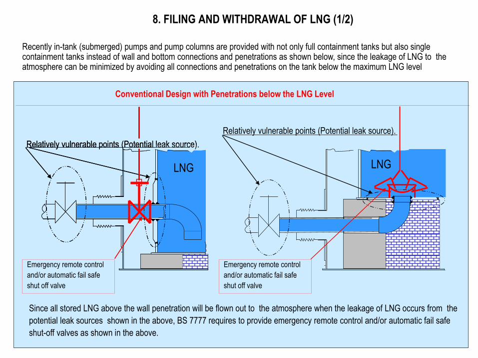
Recently in-tank (submerged) pumps and pump columns are provided with not only full containment tanks but also single containment tanks instead of wall and bottom connections and penetrations as shown below, since the leakage of LNG to the atmosphere can be minimized by avoiding all connections and penetrations on the tank below the maximum LNG level
Conventional Design with Penetrations below the LNG Level
Since all stored LNG above the wall penetration will be flown out to the atmosphere when the leakage of LNG occurs from the
potential leak sources shown in the above, BS 7777 requires to provide emergency remote control and/or automatic fail safe
shut-off valves as shown in the above.
Emergency remote control
and/or automatic fail safe
shut off valve
LNG
Relatively vulnerable points (Potential leak source).
LNG
Relatively vulnerable points (Potential leak source).
Emergency remote control
and/or automatic fail safe
shut off valve
LNG
Relatively vulnerable points (Potential leak source).
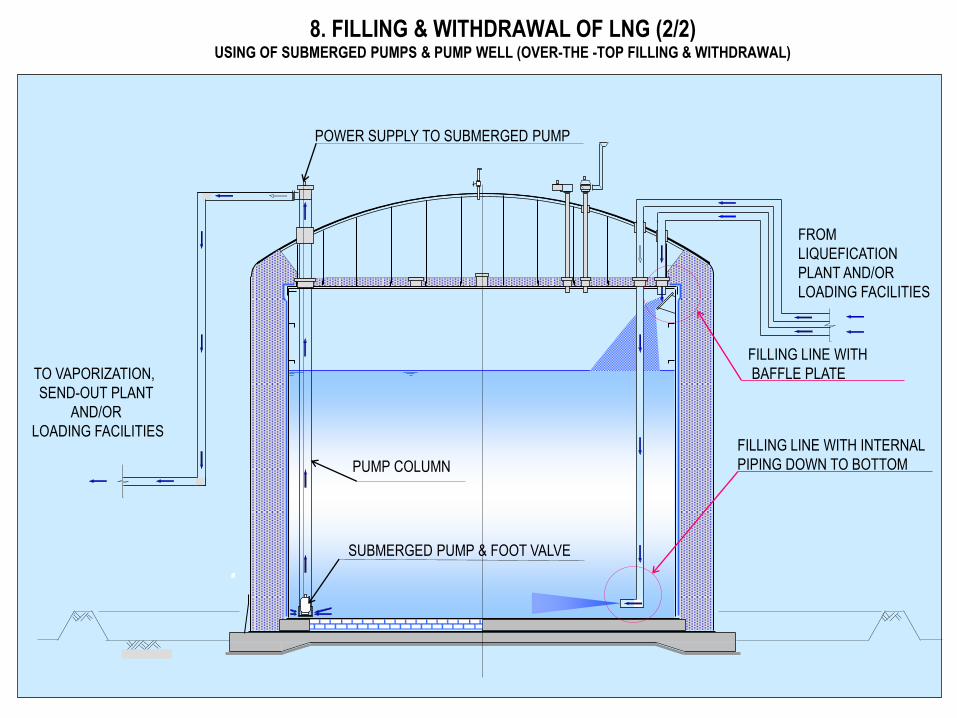
8. FILLING & WITHDRAWAL OF LNG (2/2) USING OF SUBMERGED PUMPS & PUMP WELL (OVER-THE -TOP FILLING & WITHDRAWAL)
FROM
LIQUEFICATION
PLANT AND/OR
LOADING FACILITIES
FILLING LINE WITH INTERNAL
PIPING DOWN TO BOTTOM
FILLING LINE WITH
BAFFLE PLATE
POWER SUPPLY TO SUBMERGED PUMP
PUMP COLUMN
SUBMERGED PUMP & FOOT VALVE
TO VAPORIZATION,
SEND-OUT PLANT
AND/OR
LOADING FACILITIES
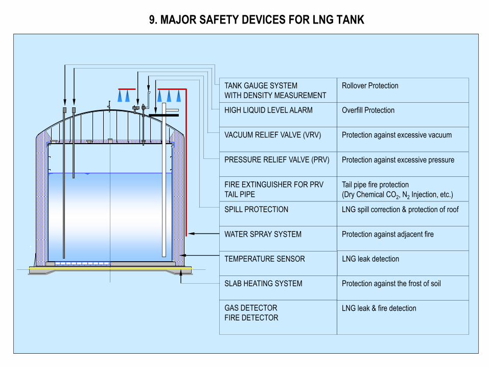
9. MAJOR SAFETY DEVICES FOR LNG TANK
Rollover Protection
Overfill Protection
VACUUM RELIEF VALVE (VRV)
Protection against excessive vacuum
Protection against excessive pressure
Tail pipe fire protection
(Dry Chemical CO2, N2 Injection, etc.)
SPILL PROTECTION
TANK GAUGE SYSTEM
WITH DENSITY MEASUREMENT
LNG spill correction & protection of roof
SLAB HEATING SYSTEM
GAS DETECTOR
FIRE DETECTOR
HIGH LIQUID LEVEL ALARM
PRESSURE RELIEF VALVE (PRV)
FIRE EXTINGUISHER FOR PRV
TAIL PIPE
WATER SPRAY SYSTEM
TEMPERATURE SENSOR
Protection against the frost of soil
Protection against adjacent fire
LNG leak & fire detection
LNG leak detection
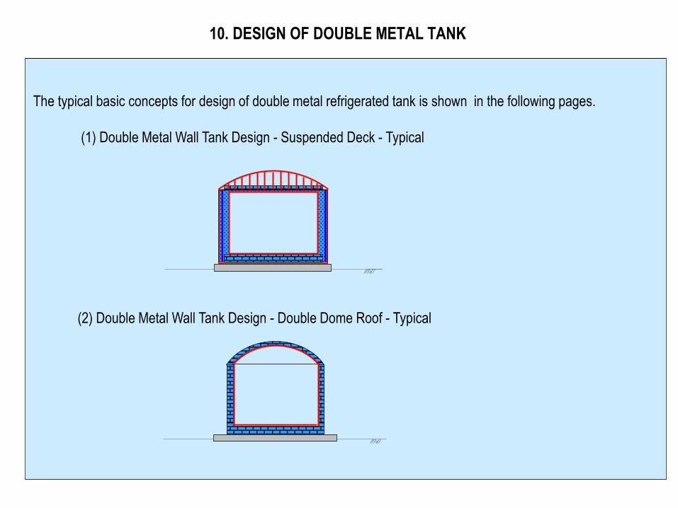
10. DESIGN OF DOUBLE METAL TANK
The typical basic concepts for design of double metal refrigerated tank is shown in the following pages.
(1) Double Metal Wall Tank Design - Suspended Deck - Typical
(2) Double Metal Wall Tank Design - Double Dome Roof - Typical
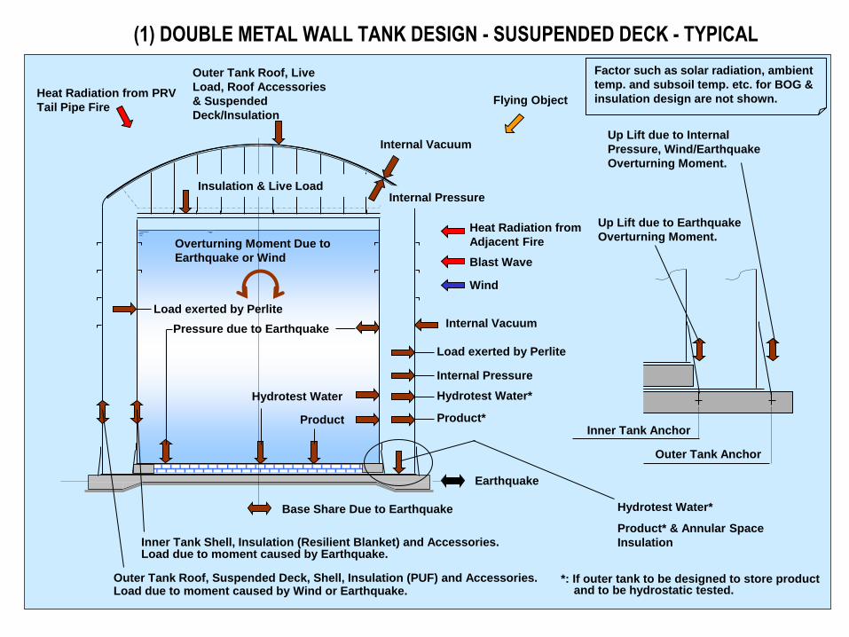
(1) DOUBLE METAL WALL TANK DESIGN - SUSUPENDED DECK - TYPICAL
Earthquake
Wind
Blast Wave
Heat Radiation from
Adjacent Fire
Heat Radiation from PRV
Tail Pipe Fire
Outer Tank Roof, Live
Load, Roof Accessories
& Suspended
Deck/Insulation
Insulation & Live Load
Pressure due to Earthquake
Product
Load exerted by Perlite
Load exerted by Perlite
Product*
Internal Pressure
Internal Vacuum
Internal Vacuum
Inner Tank Shell, Insulation (Resilient Blanket) and Accessories. Load due to moment caused by Earthquake.
Flying Object
Outer Tank Roof, Suspended Deck, Shell, Insulation (PUF) and Accessories. Load due to moment caused by Wind or Earthquake.
Hydrotest Water
Inner Tank Anchor
Outer Tank Anchor
Base Share Due to Earthquake
Overturning Moment Due to
Earthquake or Wind
Hydrotest Water*
Internal Pressure
Hydrotest Water*
Product* & Annular Space
Insulation
*: If outer tank to be designed to store product and to be hydrostatic tested.
Up Lift due to Earthquake
Overturning Moment.
Up Lift due to Internal
Pressure, Wind/Earthquake
Overturning Moment.
Factor such as solar radiation, ambient
temp. and subsoil temp. etc. for BOG &
insulation design are not shown.
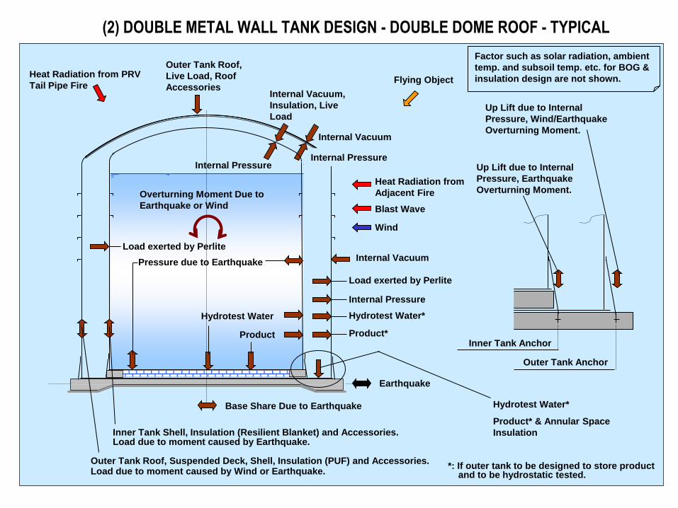
(2) DOUBLE METAL WALL TANK DESIGN - DOUBLE DOME ROOF - TYPICAL
Earthquake
Wind
Blast Wave
Heat Radiation from
Adjacent Fire
Heat Radiation from PRV
Tail Pipe Fire
Outer Tank Roof,
Live Load, Roof
Accessories
Pressure due to Earthquake
Product
Load exerted by Perlite
Load exerted by Perlite
Product*
Internal Pressure
Internal Vacuum
Internal Vacuum
Inner Tank Shell, Insulation (Resilient Blanket) and Accessories. Load due to moment caused by Earthquake.
Flying Object
Outer Tank Roof, Suspended Deck, Shell, Insulation (PUF) and Accessories. Load due to moment caused by Wind or Earthquake.
Hydrotest Water
Inner Tank Anchor
Outer Tank Anchor
Base Share Due to Earthquake
Overturning Moment Due to
Earthquake or Wind
Hydrotest Water*
Internal Pressure
Hydrotest Water*
Product* & Annular Space
Insulation
Up Lift due to Internal
Pressure, Earthquake
Overturning Moment.
Up Lift due to Internal
Pressure, Wind/Earthquake
Overturning Moment.
Internal Pressure
Factor such as solar radiation, ambient
temp. and subsoil temp. etc. for BOG &
insulation design are not shown.
Internal Vacuum,
Insulation, Live
Load
*: If outer tank to be designed to store product and to be hydrostatic tested.
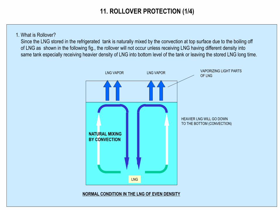
11. ROLLOVER PROTECTION (1/4)
1. What is Rollover?
Since the LNG stored in the refrigerated tank is naturally mixed by the convection at top surface due to the boiling off
of LNG as shown in the following fig., the rollover will not occur unless receiving LNG having different density into
same tank especially receiving heavier density of LNG into bottom level of the tank or leaving the stored LNG long time.
LNG
LNG VAPOR VAPORIZING LIGHT PARTS
OF LNG
NORMAL CONDITION IN THE LNG OF EVEN DENSITY
HEAVIER LNG WILL GO DOWN
TO THE BOTTOM (CONVECTION)
LNG VAPOR
NATURAL MIXING
BY CONVECTION
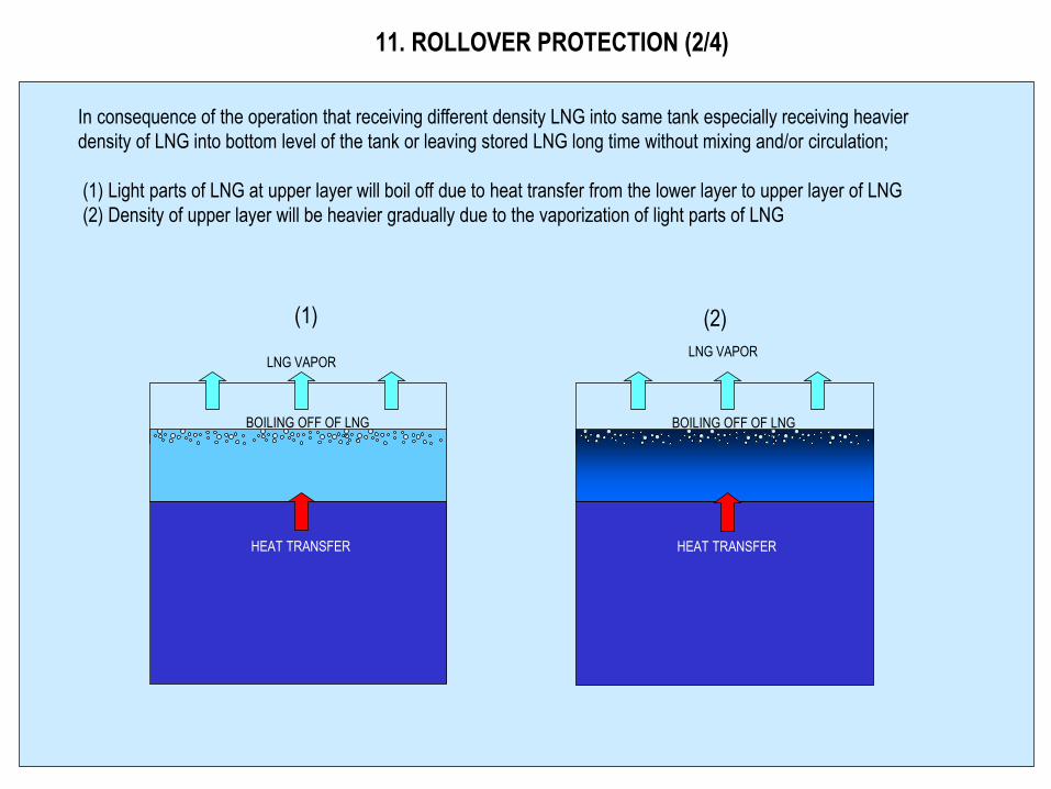
11. ROLLOVER PROTECTION (2/4)
In consequence of the operation that receiving different density LNG into same tank especially receiving heavier
density of LNG into bottom level of the tank or leaving stored LNG long time without mixing and/or circulation;
(1) Light parts of LNG at upper layer will boil off due to heat transfer from the lower layer to upper layer of LNG
(2) Density of upper layer will be heavier gradually due to the vaporization of light parts of LNG
(1) (2)
LNG VAPOR
HEAT TRANSFER
BOILING OFF OF LNG
LNG VAPOR
HEAT TRANSFER
BOILING OFF OF LNG
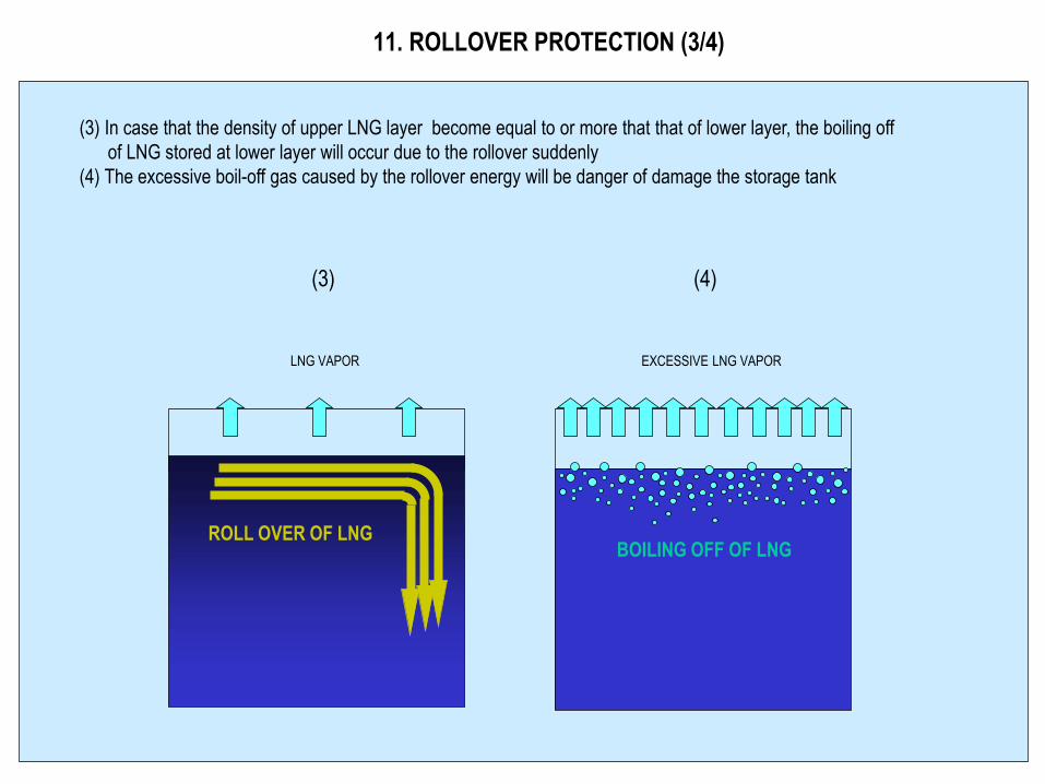
11. ROLLOVER PROTECTION (3/4)
(3) In case that the density of upper LNG layer become equal to or more that that of lower layer, the boiling off
of LNG stored at lower layer will occur due to the rollover suddenly
(4) The excessive boil-off gas caused by the rollover energy will be danger of damage the storage tank
LNG VAPOR
(3) (4)
EXCESSIVE LNG VAPOR
ROLL OVER OF LNG BOILING OFF OF LNG
11. ROLLOVER PROTECTION (4/4)
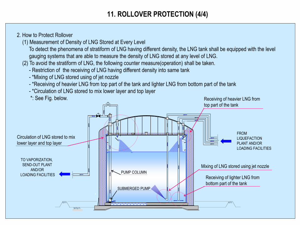
2. How to Protect Rollover
(1) Measurement of Density of LNG Stored at Every Level
To detect the phenomena of stratiform of LNG having different density, the LNG tank shall be equipped with the level
gauging systems that are able to measure the density of LNG stored at any level of LNG.
(2) To avoid the stratiform of LNG, the following counter measure(operation) shall be taken.
- Restriction of the receiving of LNG having different density into same tank
- *Mixing of LNG stored using of jet nozzle
- *Receiving of heavier LNG from top part of the tank and lighter LNG from bottom part of the tank
- *Circulation of LNG stored to mix lower layer and top layer
*: See Fig. below.
FROM
LIQUEFACTION
PLANT AND/OR
LOADING FACILITIES
Receiving of heavier LNG from
top part of the tank
PUMP COLUMN
SUBMERGED PUMP
TO VAPORIZATION,
SEND-OUT PLANT
AND/OR
LOADING FACILITIES
Mixing of LNG stored using jet nozzle
Receiving of lighter LNG from
bottom part of the tank
Circulation of LNG stored to mix
lower layer and top layer
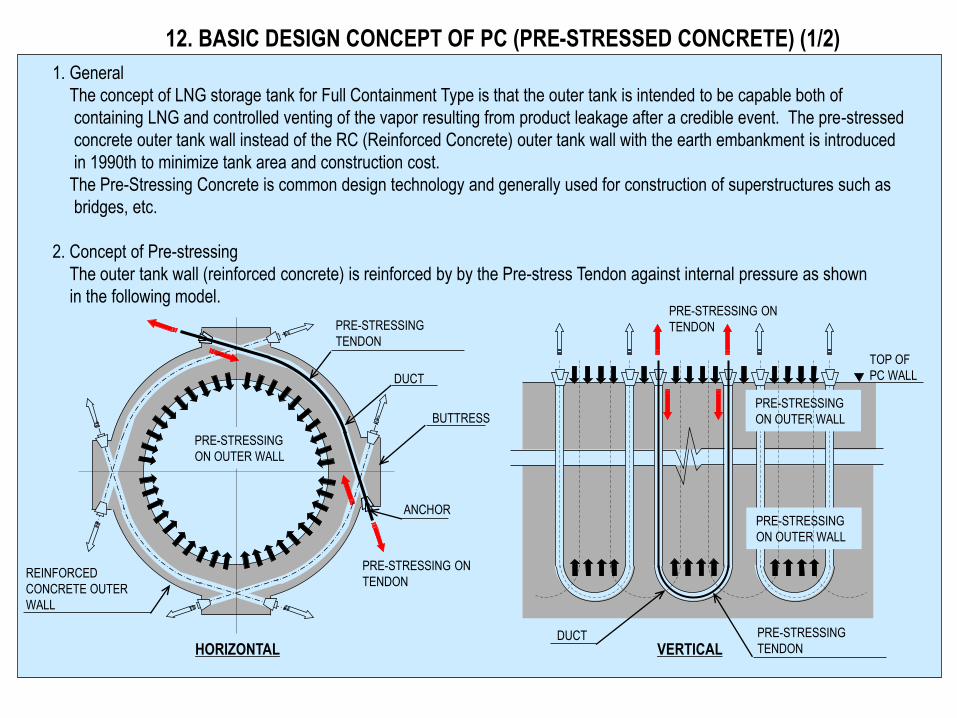
12. BASIC DESIGN CONCEPT OF PC (PRE-STRESSED CONCRETE) (1/2)
1. General
The concept of LNG storage tank for Full Containment Type is that the outer tank is intended to be capable both of
containing LNG and controlled venting of the vapor resulting from product leakage after a credible event. The pre-stressed
concrete outer tank wall instead of the RC (Reinforced Concrete) outer tank wall with the earth embankment is introduced
in 1990th to minimize tank area and construction cost.
The Pre-Stressing Concrete is common design technology and generally used for construction of superstructures such as
bridges, etc.
2. Concept of Pre-stressing
The outer tank wall (reinforced concrete) is reinforced by by the Pre-stress Tendon against internal pressure as shown
in the following model.
DUCT
ANCHOR
PRE-STRESSING
TENDON
PRE-STRESSING ON
TENDON REINFORCED
CONCRETE OUTER
WALL
BUTTRESS
HORIZONTAL
PRE-STRESSING
ON OUTER WALL
VERTICAL
PRE-STRESSING ON
TENDON
DUCT
PRE-STRESSING
ON OUTER WALL
PRE-STRESSING
ON OUTER WALL
TOP OF
PC WALL
PRE-STRESSING
TENDON
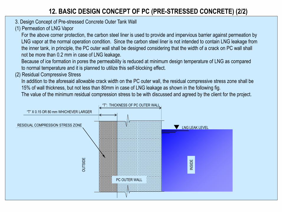
12. BASIC DESIGN CONCEPT OF PC (PRE-STRESSED CONCRETE) (2/2)
3. Design Concept of Pre-stressed Concrete Outer Tank Wall
(1) Permeation of LNG Vapor
For the above corner protection, the carbon steel liner is used to provide and impervious barrier against permeation by
LNG vapor at the normal operation condition. Since the carbon steel liner is not intended to contain LNG leakage from
the inner tank, in principle, the PC outer wall shall be designed considering that the width of a crack on PC wall shall
not be more than 0.2 mm in case of LNG leakage.
Because of ice formation in pores the permeability is reduced at minimum design temperature of LNG as compared
to normal temperature and it is planned to utilize this self-blocking effect.
(2) Residual Compressive Stress
In addition to the aforesaid allowable crack width on the PC outer wall, the residual compressive stress zone shall be
15% of wall thickness, but not less than 80mm in case of LNG leakage as shown in the following fig.
The value of the minimum residual compression stress to be with discussed and agreed by the client for the project.
OU
TS
IDE
LNG LEAK LEVEL
“T”: THICKNESS OF PC OUTER WALL
RESIDUAL COMPRESSION STRESS ZONE
“T” X 0.15 OR 80 mm WHICHEVER LARGER
PC OUTER WALL
INS
IDE
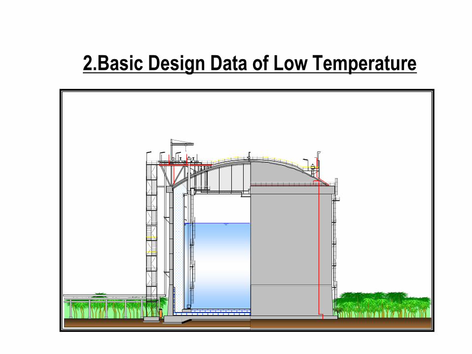
2.Basic Design Data of Low Temperature

3.1 Applicable Code
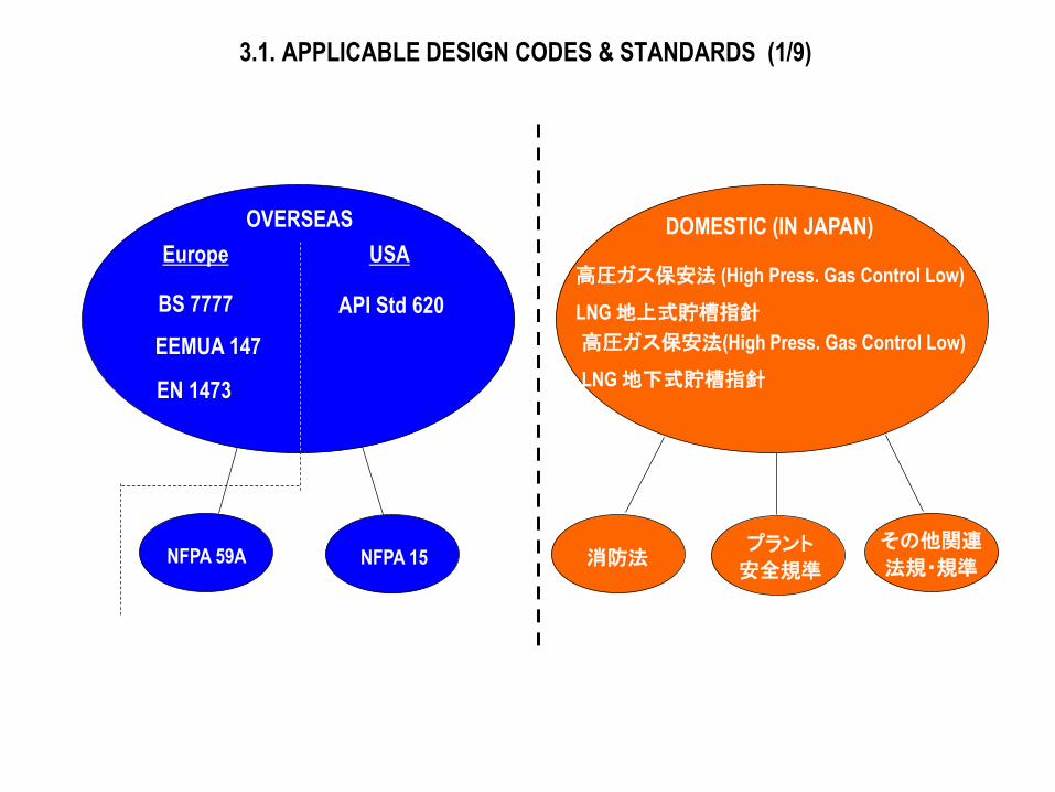
3.1. APPLICABLE DESIGN CODES & STANDARDS (1/9)
DOMESTIC (IN JAPAN)
高圧ガス保安法 (High Press. Gas Control Low)
LNG 地上式貯槽指針
高圧ガス保安法(High Press. Gas Control Low)
LNG 地下式貯槽指針
消防法 プラント
安全規準
その他関連
法規・規準
BS 7777
OVERSEAS
EEMUA 147
EN 1473
API Std 620
Europe USA
NFPA 59A NFPA 15
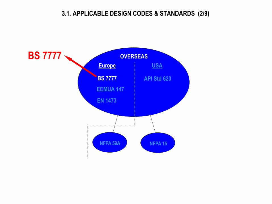
3.1. APPLICABLE DESIGN CODES & STANDARDS (2/9)
BS 7777
OVERSEAS
EEMUA 147
EN 1473
API Std 620
Europe USA
NFPA 59A NFPA 15
BS 7777
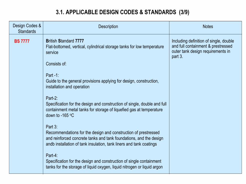
3.1. APPLICABLE DESIGN CODES & STANDARDS (3/9)
Design Codes &
Standards Description Notes
BS 7777
British Standard 7777
Flat-bottomed, vertical, cylindrical storage tanks for low temperature
service
Consists of:
Part -1:
Guide to the general provisions applying for design, construction,
installation and operation
Part-2:
Specification for the design and construction of single, double and full
containment metal tanks for storage of liquefied gas at temperature
down to -165 oC
Part 3:
Recommendations for the design and construction of prestressed
and reinforced concrete tanks and tank foundations, and the design
andb installation of tank insulation, tank liners and tank coatings
Part-4:
Specification for the design and construction of single containment
tanks for the storage of liquid oxygen, liquid nitrogen or liquid argon
Including definition of single, double and full containment & prestressed outer tank design requirements in part 3.
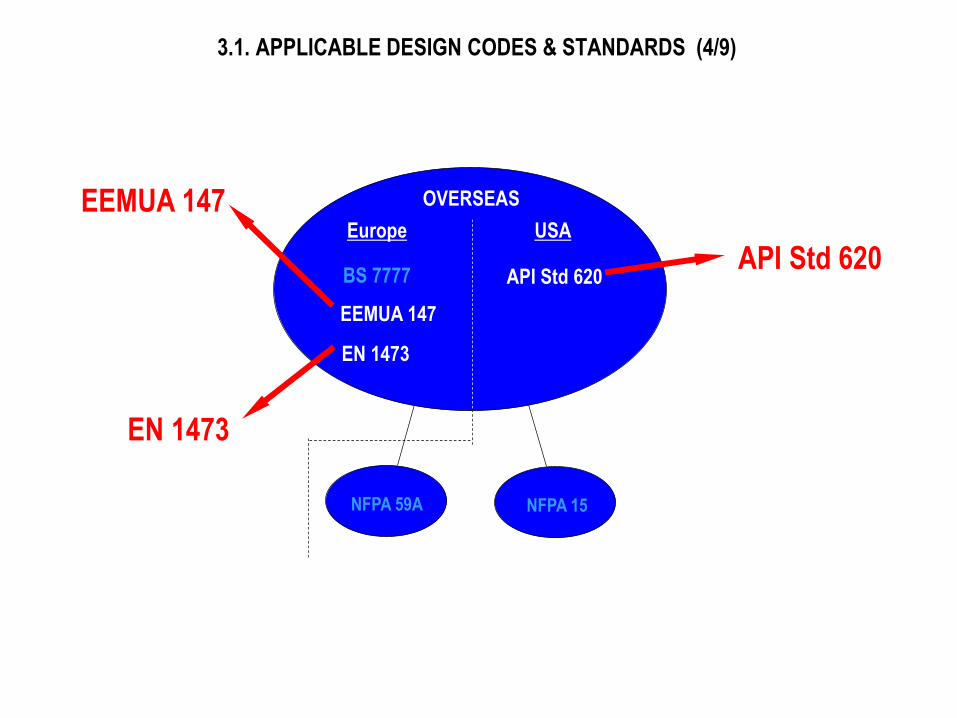
3.1. APPLICABLE DESIGN CODES & STANDARDS (4/9)
BS 7777
OVERSEAS
EEMUA 147
EN 1473
API Std 620
Europe USA
NFPA 59A NFPA 15
EEMUA 147
EN 1473
API Std 620
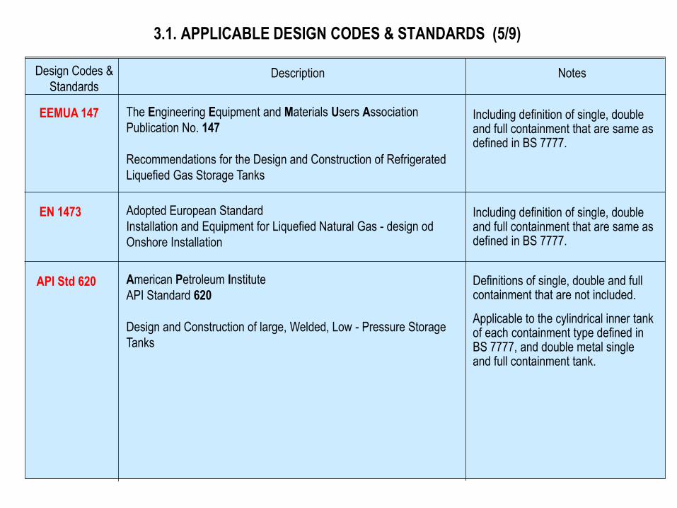
3.1. APPLICABLE DESIGN CODES & STANDARDS (5/9)
Design Codes &
Standards Description Notes
EEMUA 147 The Engineering Equipment and Materials Users Association
Publication No. 147
Recommendations for the Design and Construction of Refrigerated
Liquefied Gas Storage Tanks
Including definition of single, double and full containment that are same as defined in BS 7777.
EN 1473 Including definition of single, double and full containment that are same as defined in BS 7777.
Adopted European Standard
Installation and Equipment for Liquefied Natural Gas - design od
Onshore Installation
API Std 620
American Petroleum Institute
API Standard 620
Design and Construction of large, Welded, Low - Pressure Storage
Tanks
Definitions of single, double and full containment that are not included.
Applicable to the cylindrical inner tank of each containment type defined in BS 7777, and double metal single and full containment tank.
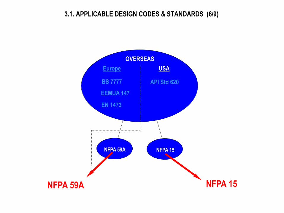
3.1. APPLICABLE DESIGN CODES & STANDARDS (6/9)
BS 7777
OVERSEAS
EEMUA 147
EN 1473
API Std 620
Europe USA
NFPA 59A NFPA 15
NFPA 59A NFPA 15
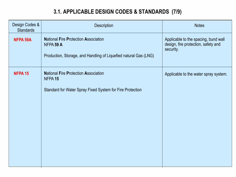
3.1. APPLICABLE DESIGN CODES & STANDARDS (7/9)
Design Codes &
Standards Description Notes
NFPA 59A
NFPA 15
National Fire Protection Association
NFPA 59 A
Production, Storage, and Handling of Liquefied natural Gas (LNG)
Applicable to the spacing, bund wall design, fire protection, safety and security.
National Fire Protection Association
NFPA 15
Standard for Water Spray Fixed System for Fire Protection
Applicable to the water spray system.
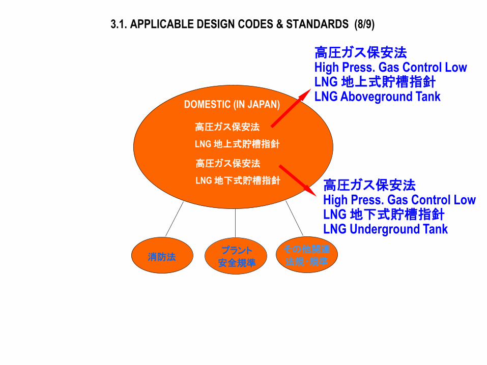
3.1. APPLICABLE DESIGN CODES & STANDARDS (8/9)
DOMESTIC (IN JAPAN)
高圧ガス保安法
LNG 地上式貯槽指針
高圧ガス保安法
LNG 地下式貯槽指針
消防法 プラント
安全規準
その他関連
法規・規準
高圧ガス保安法 High Press. Gas Control Low LNG 地上式貯槽指針 LNG Aboveground Tank
高圧ガス保安法 High Press. Gas Control Low LNG 地下式貯槽指針 LNG Underground Tank
3.1. APPLICABLE DESIGN CODES & STANDARDS (9/9)
Design Codes &
Standards Description Notes
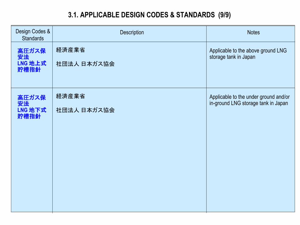
高圧ガス保安法 LNG 地上式貯槽指針
経済産業省
社団法人 日本ガス協会
Applicable to the above ground LNG storage tank in Japan
高圧ガス保安法 LNG 地下式貯槽指針
Applicable to the under ground and/or in-ground LNG storage tank in Japan
経済産業省
社団法人 日本ガス協会
3.2 Seismic Load
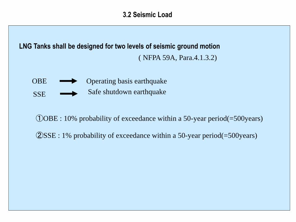
3.2 Seismic Load
①OBE : 10% probability of exceedance within a 50-year period(=500years)
LNG Tanks shall be designed for two levels of seismic ground motion
②SSE : 1% probability of exceedance within a 50-year period(=500years)
OBE
SSE
Operating basis earthquake
Safe shutdown earthquake
( NFPA 59A, Para.4.1.3.2)
3.3 Liquid Temperature
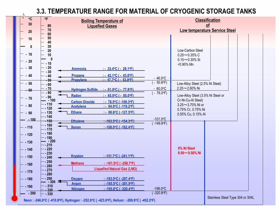
3.3. TEMPERATURE RANGE FOR MATERIAL OF CRYOGENIC STORAGE TANKS
- 200
- 190
- 180
- 170
- 160
- 150
- 140
- 130
- 120
- 110
- 100
- 90
- 80
- 70
- 60
- 50
- 40
- 30
- 20
- 10
0
10
20
30
oF oC
30
- 330
40 50 60 70 80
20 10
0 - 10 - 20 - 30 - 40 - 50 - 60 - 70 - 80 - 90
- 110 - 120 - 130 - 140 - 150 - 160 - 170 - 180 - 190
- 210 - 220 - 230 - 240 - 250 - 260 - 270 - 280 - 290
- 320 - 310
- 100
- 200
- 300
Boiling Temperature of Liquefied Gases
Classification of
Low temperature Service Steel
Ammonia : - 33.4oC ( - 28.1oF)
Propane : - 42.1oC ( - 43.8oF) Propylene : - 47.7oC ( - 53.9oF)
Hydrogen Sulfide : - 61.0oC ( - 77.8oF)
Radon : - 65.0oC ( - 85.0oF)
Carbon Dioxide : - 78.5oC ( -109.3oF) Acetylene : - 84.0oC ( -119.2oF)
- 46.0oC ( - 50.8oF)
Ethylene : -103.5oC ( -154.3oF)
Xenon : -108.0oC ( -162.4oF)
Krypton : -151.7oC ( -241.1oF)
Oxygen : -183.0oC ( -297.4oF)
Argon : -185.5oC ( -301.9oF)
Nitrogen : -195.8oC ( -320.4oF)
Low-Carbon Steel
0.20~0.35% C
0.15~0.30% Si
<0.90% Mn
Low-Alloy Steel (2.5% Ni Steel)
2.20~2.60% Ni
Low-Alloy Steel (3.5% Ni Steel or
Cr-Ni-Cu-Al Steel)
3.25~3.70% Ni or
0.75% Cr, 0.75% Ni
0.55% Cu, 0.15% Al
- 60.0oC ( - 76.0oF)
-101.0oC ( -149.8oF)
-196.0oC ( -320.8oF)
9% Ni Steel
8.50~9.50% Ni
Ethane : - 88.6oC ( -127.5oF)
Neon : -246.0oC ( -410.8oF), Hydrogen : -252.8oC ( -423.0oF), Helium : -269.0oC ( -452.2oF) Stainless Steel Type 304 or 304L
Methane : -161.5oC ( -258.7oF)
Liquefied Natural Gas (LNG)