Embed Size (px)
Citation preview
377
Related InformationFIBERSENSORS
LASERSENSORS
PHOTOELECTRICSENSORS
MICROPHOTOELECTRIC
SENSORS
AREASENSORS
LIGHTCURTAINS
PRESSURE / FLOW
SENSORSINDUCTIVEPROXIMITY
SENSORS
PARTICULARUSE SENSORS
SENSOROPTIONS
SIMPLEWIRE-SAVING
UNITS
WIRE-SAVING SYSTEMS
MEASUREMENTSENSORS
STATIC CONTROLDEVICES
ENDOSCOPE
LASERMARKERS
PLC /TERMINALS
HUMAN MACHINE INTERFACES
ENERGY CONSUMPTION VISUALIZATION COMPONENTS
FA COMPONENTS
MACHINE VISION SYSTEMS
UV CURING SYSTEMS
Selection Guide
Amplifier Built-in
Power Supply Built-in
Amplifier-separated
CX-400
EX-10
EX-20
EX-30
EX-40
CX-440
EQ-30
EQ-500
MQ-W
RX-LS200
RX
RT-610
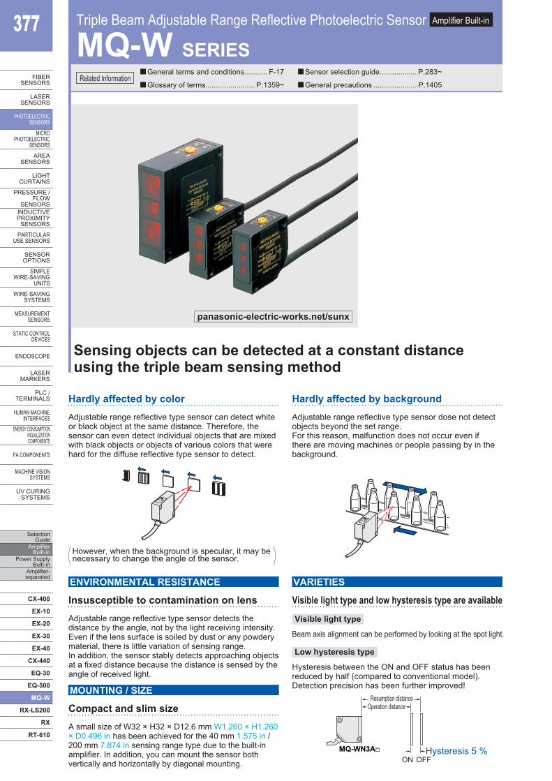
Hardly affected by colorAdjustable range reflective type sensor can detect white or black object at the same distance. Therefore, the sensor can even detect individual objects that are mixed with black objects or objects of various colors that were hard for the diffuse reflective type sensor to detect.
Hardly affected by backgroundAdjustable range reflective type sensor dose not detect objects beyond the set range.For this reason, malfunction does not occur even if there are moving machines or people passing by in the background.
Visible light type and low hysteresis type are available
Beam axis alignment can be performed by looking at the spot light.
VARIETIES
Visible light type
Low hysteresis type
Hysteresis between the ON and OFF status has been reduced by half (compared to conventional model). Detection precision has been further improved!
ON OFFHysteresis 5 %
Operation distanceResumption distance
MQ-WN3A
Insusceptible to contamination on lensAdjustable range reflective type sensor detects the distance by the angle, not by the light receiving intensity. Even if the lens surface is soiled by dust or any powdery material, there is little variation of sensing range. In addition, the sensor stably detects approaching objects at a fixed distance because the distance is sensed by the angle of received light.
ENVIRONMENTAL RESISTANCE
Compact and slim sizeA small size of W32 × H32 × D12.6 mm W1.260 × H1.260 × D0.496 in has been achieved for the 40 mm 1.575 in / 200 mm 7.874 in sensing range type due to the built-in amplifier. In addition, you can mount the sensor both vertically and horizontally by diagonal mounting.
MOUNTING / SIZE
Triple Beam Adjustable Range Reflective Photoelectric Sensor Amplifier Built-in
MQ-W SERIES
Sensing objects can be detected at a constant distanceusing the triple beam sensing method
General terms and conditions ........... F-17
Glossary of terms........................ P.1359~
Sensor selection guide .................. P.283~
General precautions ..................... P.1405
However, when the background is specular, it may be necessary to change the angle of the sensor.
panasonic-electric-works.net/sunx
Triple Beam Adjustable Range Reflective Photoelectric Sensor MQ-W SERIES 378
FIBERSENSORS
LASERSENSORS
PHOTO-ELECTRICSENSORSMICROPHOTO-ELECTRICSENSORS
AREASENSORS
LIGHTCURTAINS
PRESSURE / FLOWSENSORS
INDUCTIVEPROXIMITYSENSORS
PARTICULARUSE SENSORS
SENSOROPTIONS
SIMPLEWIRE-SAVINGUNITS
WIRE-SAVING SYSTEMS
MEASURE-MENTSENSORS
STATIC CONTROLDEVICES
ENDOSCOPE
LASERMARKERS
PLC /TERMINALS
HUMAN MACHINE INTERFACESENERGY CONSUMPTION VISUALIZATION COMPONENTS
FA COMPONENTS
MACHINE VISION SYSTEMS
UV CURING SYSTEMS
Selection GuideAmplifier Built-inPower Supply Built-inAmplifier-separated
CX-400
EX-10
EX-20
EX-30
EX-40
CX-440
EQ-30
EQ-500
MQ-W
RX-LS200
RX
RT-610
Sensing distance (rated)
Setting range (optimum)
Type Appearance Sensing range Model No.
Trip
le b
eam
adj
usta
ble
rang
e re
flect
ive
type
Sta
ndar
d (in
frare
d) 40 mm1.575 in MQ-W3A-DC12-24V
200 mm7.874 in MQ-W20A-DC12-24V
700 mm27.559 in MQ-W70A-DC12-24V
Visib
le lig
ht (r
ed)
40 mm1.575 in MQ-W3AR-DC12-24V
200 mm7.874 in MQ-W20AR-DC12-24V
Low
hys
tere
sis
(infra
red) 40 mm
1.575 in MQ-WN3A-DC12-24V
200 mm7.874 in MQ-WN20A-DC12-24V
700 mm27.559 in MQ-WN70A-DC12-24V
ORDER GUIDE
APPLICATIONS
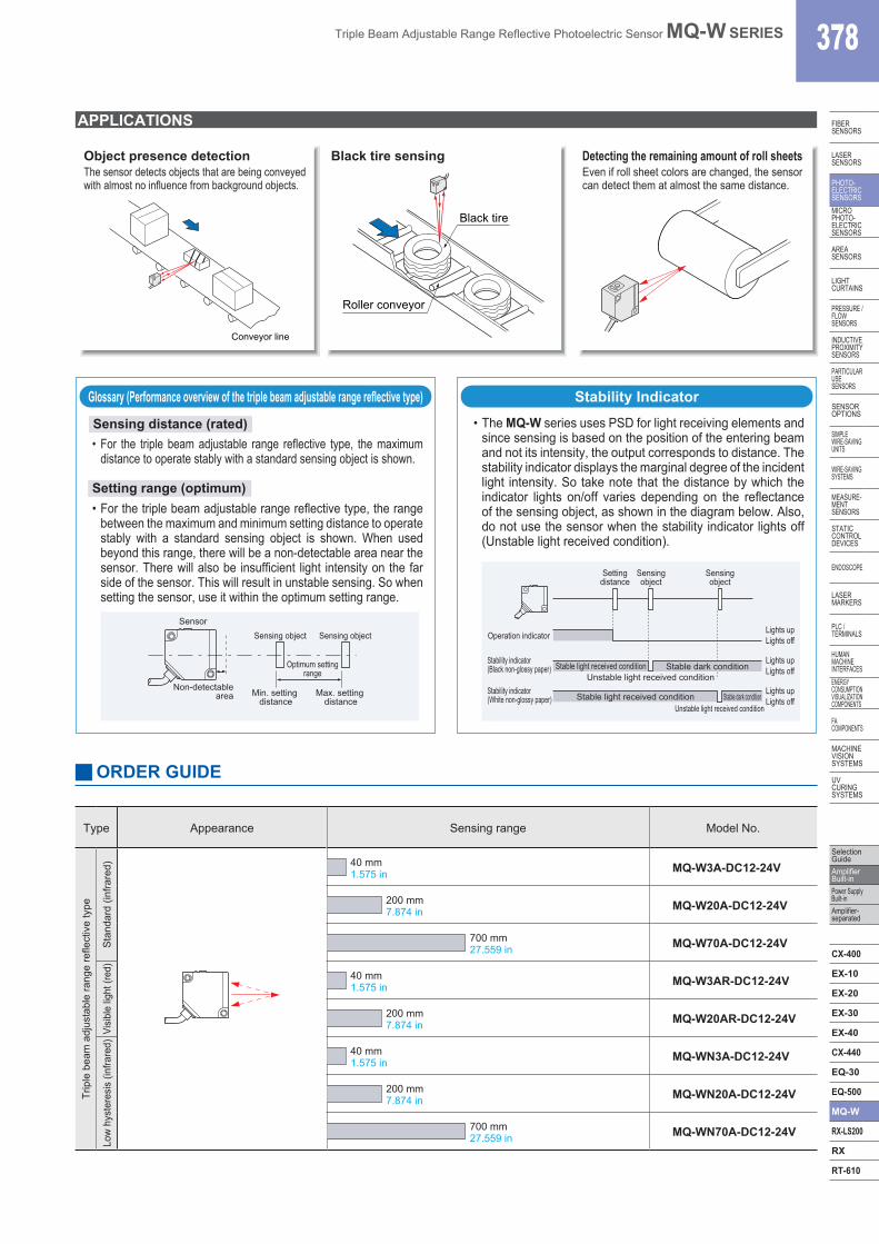
Object presence detectionThe sensor detects objects that are being conveyed with almost no influence from background objects.
Black tire sensing Detecting the remaining amount of roll sheetsEven if roll sheet colors are changed, the sensor can detect them at almost the same distance.
Conveyor line
Roller conveyor
Black tire
Glossary (Performance overview of the triple beam adjustable range reflective type)
Optimum settingrange
Sensor
Non-detectablearea
Sensing object
Min. setting distance
Max. setting distance
Sensing object Operation indicatorLights upLights off
Lights upLights off
Lights upLights off
Stability indicator(Black non-glossy paper)
Stability indicator(White non-glossy paper)
Settingdistance
Sensingobject
Sensingobject
Stable dark conditionUnstable light received condition
Stable light received condition
Stable dark conditionUnstable light received condition
Stable light received condition
Stability Indicator
• For the triple beam adjustable range reflective type, the maximum distance to operate stably with a standard sensing object is shown.
• The MQ-W series uses PSD for light receiving elements and since sensing is based on the position of the entering beam and not its intensity, the output corresponds to distance. The stability indicator displays the marginal degree of the incident light intensity. So take note that the distance by which the indicator lights on/off varies depending on the reflectance of the sensing object, as shown in the diagram below. Also, do not use the sensor when the stability indicator lights off (Unstable light received condition).
• For the triple beam adjustable range reflective type, the range between the maximum and minimum setting distance to operate stably with a standard sensing object is shown. When used beyond this range, there will be a non-detectable area near the sensor. There will also be insufficient light intensity on the far side of the sensor. This will result in unstable sensing. So when setting the sensor, use it within the optimum setting range.
Triple Beam Adjustable Range Reflective Photoelectric Sensor MQ-W SERIES379
Selection Guide
Amplifier Built-in
Power Supply Built-in
Amplifier-separated
CX-400
EX-10
EX-20
EX-30
EX-40
CX-440
EQ-30
EQ-500
MQ-W
RX-LS200
RX
RT-610
FIBERSENSORS
LASERSENSORS
PHOTO-ELECTRICSENSORS
MICROPHOTO-
ELECTRICSENSORS
AREASENSORS
LIGHTCURTAINS
PRESSURE / FLOW
SENSORS
INDUCTIVEPROXIMITY
SENSORS
PARTICULARUSE
SENSORS
SENSOROPTIONS
SIMPLEWIRE-SAVING
UNITS
WIRE-SAVING SYSTEMS
MEASURE-MENT
SENSORS
STATIC CONTROLDEVICES
ENDOSCOPE
LASERMARKERS
PLC /TERMINALS
HUMAN MACHINE
INTERFACESENERGY
CONSUMPTION VISUALIZATION COMPONENTS
FA COMPONENTS
MACHINE VISION
SYSTEMS
UV CURING
SYSTEMS
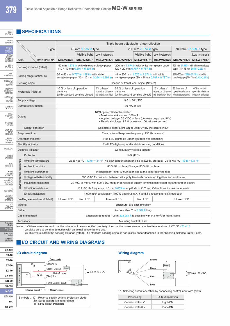
SPECIFICATIONS
Type
Triple beam adjustable range reflective
40 mm 1.575 in type 200 mm 7.874 in type 700 mm 27.559 in type
Visible light Low hysteresis Visible light Low hysteresis Low hysteresis
Item Basic Model No. MQ-W3A MQ-W3AR MQ-WN3A MQ-W20A MQ-W20AR MQ-WN20A MQ-W70A MQ-WN70A
Sensing distance (rated) 40 mm 1.575 in with white non-glossy paper(10 × 10 mm 0.394 × 0.394 in)
200 mm 7.874 in with white non-glossy paper(20 × 20 mm 0.787 × 0.787 in)
700 mm 27.559 in with white non-glossy paper (75 × 75 mm 2.953 × 2.953 in)
Setting range (optimum) 20 to 40 mm 0.787 to 1.575 in with white non-glossy paper (10 × 10 mm 0.394 × 0.394 in)
40 to 200 mm 1.575 to 7.874 in with white non-glossy paper (20 × 20mm 0.787 × 0.787 in)
200 to 700 mm 7.874 to 27.559 in with white non-glossy paper (75 × 75 mm 2.953 × 2.953 in)
Sensing object Opaque or translucent object (Note 2)
Hysteresis (Note 3)10 % or less of operation distance(with standard sensing object)
5 % or less of operation distance(with standard sensing object)
20 % or less of operation distance(with standard sensing object)
10 % or less of operation distance(with standard sensing object)
20 % or less of operation distance(with standard sensing object)
10 % or less of operation distance(with standard sensing object)
Supply voltage 9.6 to 30 V DC
Current consumption 30 mA or less
OutputNPN open-collector transistor
• Maximum sink current: 100 mA• Applied voltage: 30 V DC or less (between output and 0 V)• Residual voltage: 1.2 V or less (at 100 mA sink current)
Output operation Selectable either Light-ON or Dark-ON by the control input
Response time 2 ms or less (Response frequency: 250 Hz or more)
Operation indicator Red LED (lights up under light received condition)
Stability indicator Red LED (lights up under stable sensing condition)
Distance adjuster Continuously variable adjuster
Env
ironm
enta
l res
ista
nce
Protection IP67 (IEC)
Ambient temperature –25 to +55 °C –13 to +131 °F (No dew condensation or icing allowed), Storage: –25 to +55 °C –13 to +131 °F
Ambient humidity 85 % RH or less, Storage: 85 % RH or less
Ambient illuminance Incandescent light: 10,000 ℓx or less at the light-receiving face
Voltage withstandability 500 V AC for one min. between all supply terminals connected together and enclosure
Insulation resistance 20 MΩ, or more, with 500 V DC megger between all supply terminals connected together and enclosure
Vibration resistance 10 to 55 Hz frequency, 1.5 mm 0.059 in amplitude in X, Y and Z directions for two hours each
Shock resistance 1,000 m/s2 acceleration (100 G approx.) in X, Y and Z directions for six times each
Emitting element (modulated) Infrared LED Red LED Infrared LED Red LED Infrared LED
Material Enclosure: Die-cast zinc alloy
Cable 4-core cable, 2 m 6.562 ft long
Cable extension Extension up to total 100 m 328.084 ft is possible with 0.3 mm2, or more, cable.
Accessory Mounting bracket: 1 set
Notes: 1) Where measurement conditions have not been specified precisely, the conditions use were an ambient temperature of +23 °C +73.4 °F.2) Make sure to confirm detection with an actual sensor before use.3) This value is from the sensing distance (rated). The standard sensing object is non-glossy paper described in the “Sensing distance (rated)” item.
I/O CIRCUIT AND WIRING DIAGRAMS
*1
Brown
Black
Pink
Blue
Load
9.6 to 30 V DC+–
* 1: Selecting output operation by connecting control input wire (pink)
Processing Output operation
Connected to +V Light-ON
Connected to 0 V Dark-ON
*1(Pink) Control input
100mA max.
Color code
Load
Users’ circuitInternal circuit
Sen
sor
circ
uit
D
ZDTr
9.6 to 30 V DC+–
(Blue) 0 V
(Black) Output
(Brown) +V
I/O circuit diagram Wiring diagram
Symbols … D : Reverse supply polarity protection diodeZD: Surge absorption zener diodeTr : NPN output transistor
Triple Beam Adjustable Range Reflective Photoelectric Sensor MQ-W SERIES 380
FIBERSENSORS
LASERSENSORS
PHOTO-ELECTRICSENSORSMICROPHOTO-ELECTRICSENSORS
AREASENSORS
LIGHTCURTAINS
PRESSURE / FLOWSENSORS
INDUCTIVEPROXIMITYSENSORS
PARTICULARUSE SENSORS
SENSOROPTIONS
SIMPLEWIRE-SAVINGUNITS
WIRE-SAVING SYSTEMS
MEASURE-MENTSENSORS
STATIC CONTROLDEVICES
ENDOSCOPE
LASERMARKERS
PLC /TERMINALS
HUMAN MACHINE INTERFACESENERGY CONSUMPTION VISUALIZATION COMPONENTS
FA COMPONENTS
MACHINE VISION SYSTEMS
UV CURING SYSTEMS
Selection GuideAmplifier Built-inPower Supply Built-inAmplifier-separated
CX-400
EX-10
EX-20
EX-30
EX-40
CX-440
EQ-30
EQ-500
MQ-W
RX-LS200
RX
RT-610
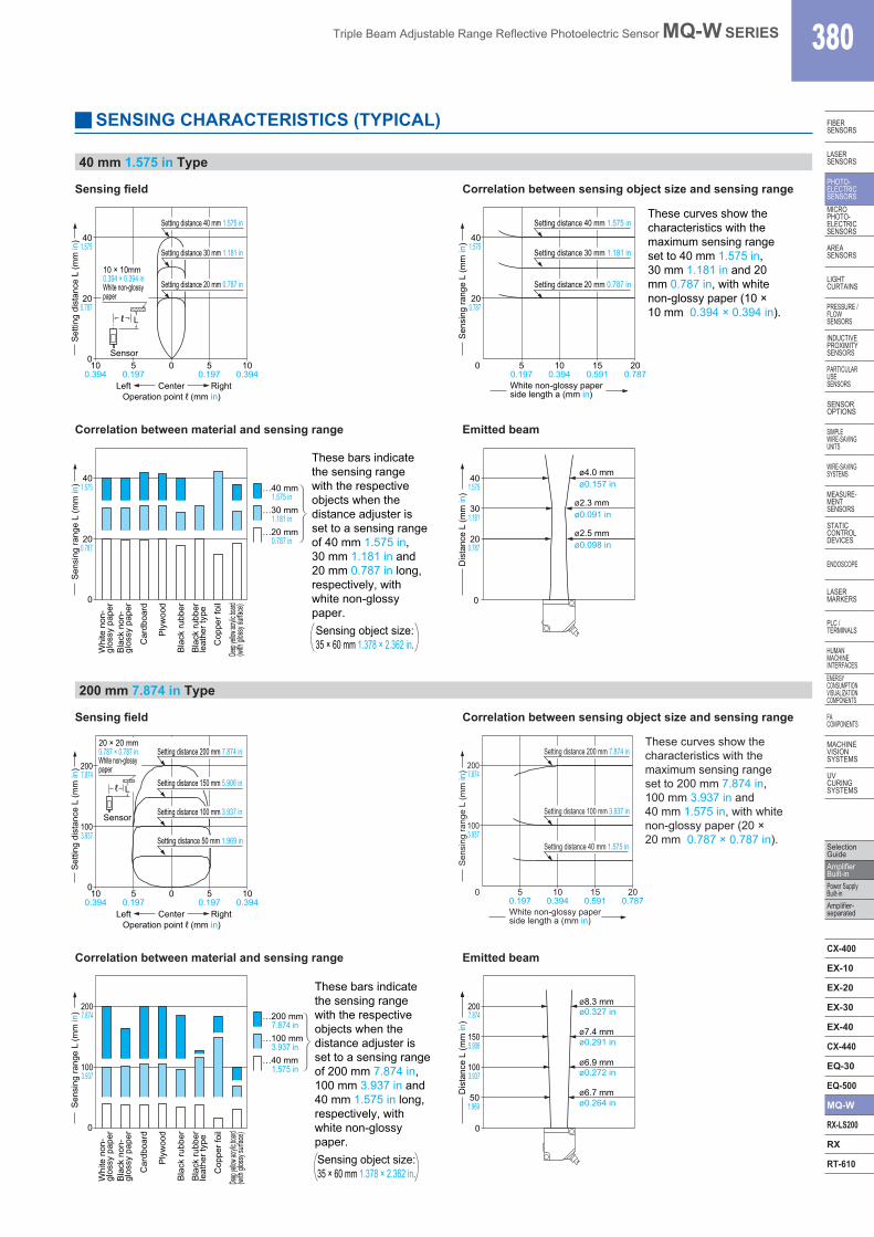
SENSING CHARACTERISTICS (TYPICAL)
40 mm 1.575 in Type
Operation point ℓ (mm in)
200.787
100.394
05
0.1970 5
0.19710
0.394
401.575
CenterLeft Right
Set
ting
dist
ance
L (m
m in
)
Setting distance 30 mm 1.181 in
Setting distance 20 mm 0.787 in
Setting distance 40 mm 1.575 in
Lℓ
Sensor
10 × 10mm0.394 × 0.394 inWhite non-glossypaper 20
0.787
401.575
50.197
0 100.394
150.591
200.787
White non-glossy paperside length a (mm in)
Setting distance 30 mm 1.181 in
Setting distance 20 mm 0.787 in
Setting distance 40 mm 1.575 inThese curves show the characteristics with the maximum sensing range set to 40 mm 1.575 in, 30 mm 1.181 in and 20 mm 0.787 in, with white non-glossy paper (10 × 10 mm 0.394 × 0.394 in).
Sen
sing
rang
e L
(mm
in)
Sensing field Correlation between sensing object size and sensing range
Correlation between material and sensing range Emitted beam
200.787
0
401.575
Whi
te n
on-
glos
sy p
aper
Car
dboa
rd
Ply
woo
d
Bla
ck ru
bber
Cop
per f
oil
Bla
ck ru
bber
leat
her t
ype
Deep
yellow
acryli
c boar
d(w
ith gl
ossy
surfa
ce)
Bla
ck n
on-
glos
sy p
aper
…40 mm 1.575 in…30 mm 1.181 in…20 mm 0.787 in
Sensing object size:35 × 60 mm 1.378 × 2.362 in.
These bars indicate the sensing range with the respective objects when the distance adjuster is set to a sensing range of 40 mm 1.575 in, 30 mm 1.181 in and 20 mm 0.787 in long, respectively, with white non-glossy paper.
Sen
sing
rang
e L
(mm
in)
301.181
0
Dis
tanc
e L
(mm
in)
ø2.5 mmø0.098 in
ø2.3 mmø0.091 in
ø4.0 mmø0.157 in
200.787
401.575
200 mm 7.874 in Type
Sensing field Correlation between sensing object size and sensing range
Setting distance 50 mm 1.969 in
Setting distance 100 mm 3.937 in
Setting distance 150 mm 5.906 in
Setting distance 200 mm 7.874 in
Lℓ
Sensor
20 × 20 mm0.787 × 0.787 inWhite non-glossypaper
1003.937
100.394
05
0.1970 5
0.19710
0.394
2007.874
Operation point ℓ (mm in)CenterLeft Right
Set
ting
dist
ance
L (m
m in
)
100 3.937
200 7.874
5 0.197
0 10 0.394
15 0.591
20 0.787
Setting distance 40 mm 1.575 in
Setting distance 100 mm 3.937 in
Setting distance 200 mm 7.874 in These curves show the characteristics with the maximum sensing range set to 200 mm 7.874 in, 100 mm 3.937 in and 40 mm 1.575 in, with white non-glossy paper (20 × 20 mm 0.787 × 0.787 in).
Sen
sing
rang
e L
(mm
in)
White non-glossy paper side length a (mm in)
Correlation between material and sensing range Emitted beam
…200 mm 7.874 in…100 mm 3.937 in…40 mm 1.575 in100
3.937
0
2007.874
Car
dboa
rd
Ply
woo
d
Bla
ck ru
bber
Sensing object size:35 × 60 mm 1.378 × 2.362 in.
These bars indicate the sensing range with the respective objects when the distance adjuster is set to a sensing range of 200 mm 7.874 in, 100 mm 3.937 in and 40 mm 1.575 in long, respectively, with white non-glossy paper.
Cop
per f
oil
Bla
ck ru
bber
leat
her t
ype
Deep
yellow
acryli
c boar
d(w
ith gl
ossy
surfa
ce)
Whi
te n
on-
glos
sy p
aper
Bla
ck n
on-
glos
sy p
aper
Sen
sing
rang
e L
(mm
in)
1003.937
501.969
1505.906
0
2007.874
Dis
tanc
e L
(mm
in)
ø8.3 mm
ø7.4 mm
ø6.9 mm
ø6.7 mm
ø0.327 in
ø0.291 in
ø0.272 in
ø0.264 in
Triple Beam Adjustable Range Reflective Photoelectric Sensor MQ-W SERIES381
Selection Guide
Amplifier Built-in
Power Supply Built-in
Amplifier-separated
CX-400
EX-10
EX-20
EX-30
EX-40
CX-440
EQ-30
EQ-500
MQ-W
RX-LS200
RX
RT-610
FIBERSENSORS
LASERSENSORS
PHOTO-ELECTRICSENSORS
MICROPHOTO-
ELECTRICSENSORS
AREASENSORS
LIGHTCURTAINS
PRESSURE / FLOW
SENSORS
INDUCTIVEPROXIMITY
SENSORS
PARTICULARUSE
SENSORS
SENSOROPTIONS
SIMPLEWIRE-SAVING
UNITS
WIRE-SAVING SYSTEMS
MEASURE-MENT
SENSORS
STATIC CONTROLDEVICES
ENDOSCOPE
LASERMARKERS
PLC /TERMINALS
HUMAN MACHINE
INTERFACESENERGY
CONSUMPTION VISUALIZATION COMPONENTS
FA COMPONENTS
MACHINE VISION
SYSTEMS
UV CURING
SYSTEMS
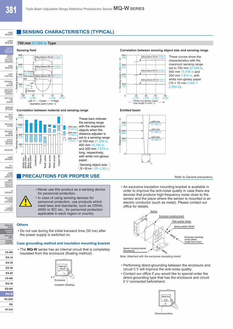
SENSING CHARACTERISTICS (TYPICAL)
700 mm 27.559 in Type
Sensing field Correlation between sensing object size and sensing range
200.787
100.394
0 100.394
200.787
0
2007.874
40015.748
60023.622
80031.496 Setting distance 700 mm 27.559 in
Setting distance 500 mm 19.685 in
Setting distance 300 mm 11.811 in
75 × 75 mm 2.953 × 2.953 inWhite non-glossypaper
Operation point ℓ (mm in)CenterLeft Right
Set
ting
dist
ance
L (m
m in
)
L
Sensor
ℓ
White non-glossy paper side length a (mm in)
20 0.787
40 1.575
60 2.362
80 3.150
0
200 7.874
400 15.748
800 31.496
600 23.622
Setting distance 700 mm 27.559 in
Setting distance 400 mm 15.748 in
Setting distance 200 mm 7.874 in
These curves show the characteristics with the maximum sensing range set to 700 mm 27.559 in, 400 mm 15.748 in and 200 mm 7.874 in, with white non-glossy paper (75 × 75 mm 2.953 × 2.953 in).S
ensi
ng ra
nge
L (m
m in
)
Correlation between material and sensing range Emitted beam
0
…700 mm 27.559 in…400 mm 15.748 in…200 mm 7.874 in
Ply
woo
d
Bla
ck ru
bber
Bla
ck a
cryl
ic
Whi
te a
cryl
ic
Cop
per f
oil
Sensing object size:35 × 60 mm 1.378 × 2.362 in.
These bars indicate the sensing range with the respective objects when the distance adjuster is set to a sensing range of 700 mm 27.559 in, 400 mm 15.748 in and 200 mm 7.874 in long, respectively, with white non-glossy paper.
2007.874
40015.748
60023.622
80031.496
Sen
sing
rang
e L
(mm
in)
Car
dboa
rd
Whi
te n
on-
glos
sy p
aper
Bla
ck n
on-
glos
sy p
aper
0
70027.559
30011.811
50019.685
Dis
tanc
e L
(mm
in)
ø1.535 in
ø1.299 in
ø0.906 in
ø39 mm
ø33 mm
ø23 mm
PRECAUTIONS FOR PROPER USE Refer to General precautions.
• An exclusive insulation mounting bracket is available in order to improve the anti-noise quality in case there are devices that produce high-frequency noise close to the sensor and the place where the sensor is mounted is an electric conductor (such as metal). Please contact our office for details.
Sensor mouting bracket (Accessory)
Exclusive mounting screw (Note)(made from resin)
Sensor
Exclusive insulating board
Spring washer (Note)
Plain washer (Note)
Note: Attached with the exclusive insulating board.
• Performing direct-grounding between the enclosure and circuit 0 V will improve the anti-noise quality.
• Contact our office if you would like to special-order the direct-grounding type that has the enclosure and circuit 0 V connected beforehand.
Internal circuit
Direct-grounding
0 V
Case grounding method and insulation mounting bracket
• The MQ-W series has an internal circuit that is completely insulated from the enclosure (floating method).
Internalcircuit
Insulation (floating)
Enclosure0 V
Others
• Do not use during the initial transient time (50 ms) after the power supply is switched on.
• Never use this product as a sensing device for personnel protection.
• In case of using sensing devices for personnel protection, use products which meet laws and standards, such as OSHA, ANSI or IEC etc., for personnel protection applicable in each region or country.
Triple Beam Adjustable Range Reflective Photoelectric Sensor MQ-W SERIES 382
FIBERSENSORS
LASERSENSORS
PHOTO-ELECTRICSENSORSMICROPHOTO-ELECTRICSENSORS
AREASENSORS
LIGHTCURTAINS
PRESSURE / FLOWSENSORS
INDUCTIVEPROXIMITYSENSORS
PARTICULARUSE SENSORS
SENSOROPTIONS
SIMPLEWIRE-SAVINGUNITS
WIRE-SAVING SYSTEMS
MEASURE-MENTSENSORS
STATIC CONTROLDEVICES
ENDOSCOPE
LASERMARKERS
PLC /TERMINALS
HUMAN MACHINE INTERFACESENERGY CONSUMPTION VISUALIZATION COMPONENTS
FA COMPONENTS
MACHINE VISION SYSTEMS
UV CURING SYSTEMS
Selection GuideAmplifier Built-inPower Supply Built-inAmplifier-separated
CX-400
EX-10
EX-20
EX-30
EX-40
CX-440
EQ-30
EQ-500
MQ-W
RX-LS200
RX
RT-610
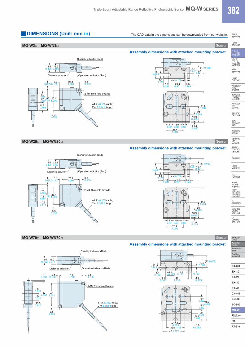
MQ-W3 MQ-WN3 Sensor
Assembly dimensions with attached mounting bracket
12.60.496
12.20.480
Distance adjuster
Stability indicator (Red)
6.30.2486.3
0.24832
1.260
11.70.461
3.30.130
3.30.130
2-M4 Thru-hole threads
ø4.2 ø0.165 cable, 2 m 6.562 ft long
25.41.000
25.41.000
Operation indicator (Red)
3.30.130
10.039
25.41.000
16.60.654 t 1.4
t 0.055
240.945
44.81.764
10.90.429
40.157
40.157
2.20.087
4.4 0.1737.3
0.2876.3
0.24824.40.961
10.70.421
(17 0.669)
4.40.173
160.630
MQ-W20 MQ-WN20 Sensor
12.60.496
12.20.480
7.50.295
7.50.295 32
1.260
10.50.413
3.30.130
3.30.130
25.41.000
25.41.000
3.30.130
10.039
Distance adjuster
Stability indicator (Red)
Operation indicator (Red)
2-M4 Thru-hole threads
ø4.2 ø0.165 cable, 2 m 6.562 ft long
7.30.287
6.30.248
24.40.961
25.41.000
16.60.654 t 1.4
t 0.055
240.945
44.81.764
10.90.429
40.157
40.157
2.20.087
4.4 0.173
10.70.421
(17 0.669)
4.40.173
160.630
MQ-W70 MQ-WN70 Sensor
18.60.732
18.20.717
3.50.138
Distance adjuster
130.512
130.512 52
2.047
15.50.610
3.50.138
3.50.138
2-M4 Thru-hole threads
451.772
451.772
10.039
Stability indicator (Red)
Operation indicator (Red)
ø4.2 ø0.165 cable, 2 m 6.562 ft long
190.748
40.157
4.40.173
9.10.358
8.10.319
441.732
ø4.5ø0.177
12.70.500
(22 0.866)
4.40.173
36.6 1.441
17.40.685 t 1.6
t 0.063
12.50.492
240.945
68.22.660
45 1.772
12.50.492
12.40.488
DIMENSIONS (Unit: mm in) The CAD data in the dimensions can be downloaded from our website.
Assembly dimensions with attached mounting bracket
Assembly dimensions with attached mounting bracket