Embed Size (px)
Citation preview
P.322
P.331
P.342
RoHS
101620253040
ø4ø6
ø10ø16ø20
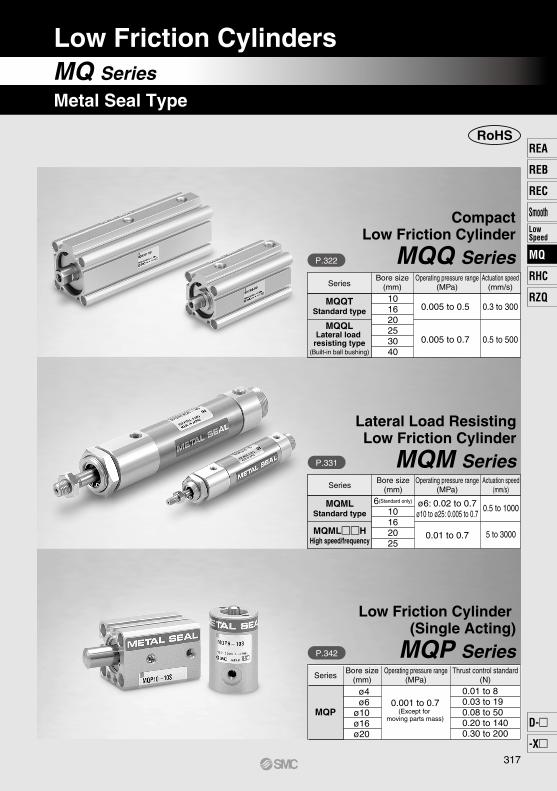
CompactLow Friction Cylinder
MQQ Series
Lateral Load ResistingLow Friction Cylinder
MQM Series
Low Friction Cylinder (Single Acting)
MQP Series
SeriesBore size
(mm)Operating pressure range
(MPa)Actuation speed
(mm/s)
MQQTStandard type
MQQLLateral load
resisting type(Built-in ball bushing)
0.005 to 0.5
0.005 to 0.7
0.3 to 300
0.5 to 500
MQMLStandard type
MQMLHHigh speed/frequency
SeriesBore size
(mm)Operating pressure range
(MPa)Actuation speed
(mm/s)
6(Standard only)
10162025
ø6: 0.02 to 0.7ø10 to ø25: 0.005 to 0.7
0.01 to 0.7
0.5 to 1000
5 to 3000
Series
MQP
Bore size(mm)
Operating pressure range(MPa)
Thrust control standard(N)
0.001 to 0.7(Except for
moving parts mass)
0.01 to 80.03 to 190.08 to 500.20 to 1400.30 to 200
MQ Series
Low Friction Cylinders
Metal Seal Type
317
REA
REB
REC
SmoothLowSpeed
MQ
RHC
RZQ
D-
-X
MQ
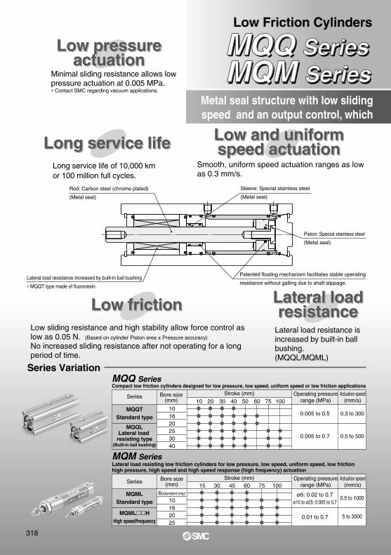
Long service life of 10,000 km or 100 million full cycles.
Metal seal structure with low slidingspeed and an output control, which
Lateral loadresistance
Low pressureactuation
Long service life
Lateral loadresistance
Low pressureactuation
Minimal sliding resistance allows low pressure actuation at 0.005 MPa.∗ Contact SMC regarding vacuum applications.
Long service life
Low frictionLow friction
Low and uniformspeed actuationLow and uniformspeed actuation
101620253040
10 20 30 40 50 60 75 100
15 30 45 60 75 100
MQQ SeriesMQQ SeriesMQM SeriesMQM Series
Low Friction Cylinders
Low sliding resistance and high stability allow force control as low as 0.05 N. (Based on cylinder Piston area x Pressure accuracy)
No increased sliding resistance after not operating for a long period of time.
Smooth, uniform speed actuation ranges as low as 0.3 mm/s.
Lateral load resistance isincreased by built-in ball bushing.(MQQL/MQML)
Rod: Carbon steel (chrome plated)
(Metal seal)
Sleeve: Special stainless steel
(Metal seal)
Piston: Special stainless steel
(Metal seal)
Lateral load resistance increased by built-in ball bushing
∗ MQQT type made of fluororesin.
Patented floating mechanism facilitates stable operating
resistance without galling due to shaft slippage.
Series Variation
MQQTStandard type
Series
MQQLLateral load
resisting type(Built-in ball bushing)
MQM SeriesLateral load resisting low friction cylinders for low pressure, low speed, uniform speed, low friction high pressure, high speed and high speed response (high frequency) actuation
MQQ SeriesCompact low friction cylinders designed for low pressure, low speed, uniform speed or low friction applications
MQMLStandard type
ø6: 0.02 to 0.7ø10 to ø25: 0.005 to 0.7
0.01 to 0.7
0.5 to 1000
5 to 3000MQMLH
High speed/frequency
Series Bore size(mm)
Stroke (mm) Operating pressurerange (MPa)
Actuation speed(mm/s)
0.005 to 0.5
0.005 to 0.7
0.3 to 300
0.5 to 500
Stroke (mm) Operating pressurerange (MPa)
Actuation speed(mm/s)
Bore size(mm)
6(standard only)
10162025
318
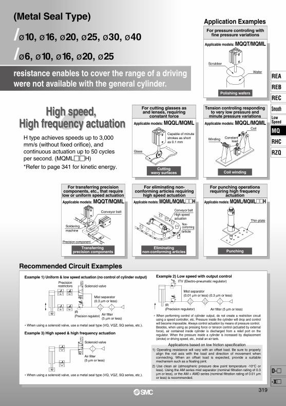
Recommended Circuit Examples
Example 1) Uniform & low speed actuation (no control of cylinder output)
Example 3) High speed & high frequency actuation
∗ When using a solenoid valve, use a metal seal type (VQ, VQZ, SQ series, etc.).
High speed, High frequency actuation
High speed, High frequency actuation
Applicable models: MQQT/MQML
Application ExamplesFor pressure controling with
fine pressure variations
Polishing wafers
Applicable models: MQQL/MQML Applicable models: MQQL/MQML
Cuttingwavy surfaces Coil winding
Tension controling respondingto very low pressure and
minute pressure variations
For cutting glasses asand lenses, requiring
constant force
Applicable models: MQML/MQMLH Applicable models: MQML/MQMLHApplicable models: MQQT/MQML
PunchingEliminating
non-conforming articles
For punching operationsrequiring high frequency
actuation
For eliminating non-conforming articles requiring
high speed actuation
Transferring precision components
For transferring precision components, etc., that require low or uniform speed actuation
resistance enables to cover the range of a driving were not available with the general cylinder.
H type achieves speeds up to 3,000 mm/s (without fixed orifice), and continuous actuation up to 50 cycles per second. (MQMLH)
*Refer to page 341 for kinetic energy.
∗ When using a solenoid valve, use a metal seal type (VQ, VQZ, SQ series, etc.).
Example 2) Low speed with output control
Applications based on low friction specification1) Operating resistance will vary with an offset load. Be sure to properly
align the rod axis with the load and direction of movement when connecting. When an offset load is expected, provide a suitable mechanism such as a floating joint.
2) Use clean air (atmospheric pressure dew point temperature -10°C or less). Using the AM series mist separator (nominal filtration rating of 0.3 µm or less), or the AM + AMD series (nominal filtration rating of 0.01 µm or less) is recommended.
∗ When performing control of cylinder output, do not create a restriction circuit using a speed controller, etc. Pressure inside the cylinder will drop and control will become impossible. Always control actuation by means of pressure control.Besides, when using as pressing force or tension control (actuated by external force), air contained inside cylinder is discharged from a relief port on the regulator. When the pressure inside a cylinder is increased by displacement (stroke) or driving speed, etc., install an air tank.
Coil
Winding Constantload
Glass
Capable of minutestrokes as short as 0.1 mm
Solderingmachine
Conveyor belt
Precision component
Thin plate
Conveyor beltHigh speed actuation
Non-conformingarticle
Scrubber
Wafer
/ø10, ø16, ø20, ø25, ø30, ø40
/ø6, ø10, ø16, ø20, ø25
(Metal Seal Type)
W
Solenoid valve
Air filter(5 µm or less)
IR(Precision regulator)
Solenoid valve
Air filter(5 µm or less)
Mist separator(0.01 µm or less) (0.3 µm or less)
ITV (Electro-pneumatic regulator)
Air filter (5 µm or less)IR(Precision regulator)
W
Precisionrestrictors
Mist separator(0.3 µm or less)
319
REA
REB
REC
SmoothLowSpeed
MQ
RHC
RZQ
D-
-X
MQ
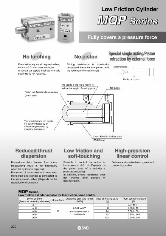
Low Friction Cylinder
MQP SeriesMQP Series
Reduced thrustdispersion
Reduced thrustdispersion
Low friction and soft-touching
Low friction and soft-touching
High-precisionlinear control
High-precisionlinear control
No pistonNo pistonNo lurchingNo lurching Special single acting/Piston retraction by external force
Special single acting/Piston retraction by external force
Fully covers a pressure force
Sliding resistance is drastically decreased because the piston and the rod share the same shaft.
External force
Dispersion of piston diameter: 3 µm or lessReadjusting thrust is not necessary when the cylinder is replaced.Dispersion of thrust does not occur even more than one cylinder is connected to the same circuit, either. (Depends on the operation environment.)
Possible to control the output in increments of 0.01 N. (Depends on the piston area of a cylinder x pressure accuracy)In addition, sliding resistance does not change after periods of non-operation.
Delicate and precise linear movement control is possible.
Even extremely small degree lurching such as 0.01 mm does not occur. A special air supply, such as for static bearings, is not required.
MQP SeriesLow friction cylinder suitable for low friction, force control.
Bore size [mm](Pressure receiving diameter)
ø 4ø 6ø10ø16ø20
Mass of moving parts [g]
48
2462
103
Thrust control standard [N]
0.01 to 80.03 to 190.08 to 500.20 to 1400.30 to 200
Stroke [mm]
10
Operating pressure range [MPa]
0.001 to 0.7(Excluding the mass of
moving parts)
For force control
Piston rod: Special stainless steel
(Metal seal)
The inside of the rod is hollow to
reduce the weight of moving parts. No piston
Liner: Special stainless steel
(Metal seal)
The special shape rod end is not easily effected by an offset load generated by mounting inaccuracy.
320
Mist separator (0.3 µm or less)
ITV (Electro-pneumatic
regulator)
Air filter (5 µm or less)
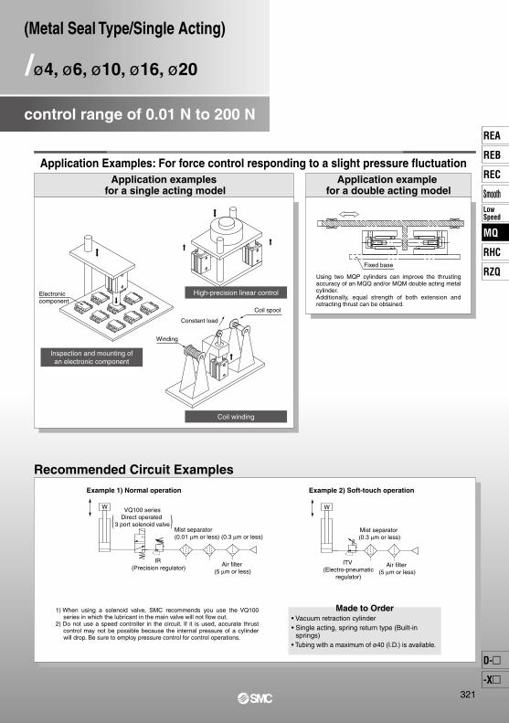
Application Examples: For force control responding to a slight pressure fluctuation
/ø4, ø6, ø10, ø16, ø20
(Metal Seal Type/Single Acting)
control range of 0.01 N to 200 N
Application examples for a single acting model
Application example for a double acting model
Using two MQP cylinders can improve the thrusting accuracy of an MQQ and/or MQM double acting metal cylinder.Additionally, equal strength of both extension and retracting thrust can be obtained.
Recommended Circuit Examples
1) When using a solenoid valve, SMC recommends you use the VQ100 series in which the lubricant in the main valve will not flow out.
2) Do not use a speed controller in the circuit. If it is used, accurate thrust control may not be possible because the internal pressure of a cylinder will drop. Be sure to employ pressure control for control operations.
Example 1) Normal operation
• Vacuum retraction cylinder• Single acting, spring return type (Built-in
springs)• Tubing with a maximum of ø40 (I.D.) is available.
Made to Order
Example 2) Soft-touch operation
Inspection and mounting ofan electronic component
Coil winding
High-precision linear controlElectronic component
Winding
Constant load
Coil spool
( )VQ100 series
Direct operated 3 port solenoid valve
Mist separator (0.01 µm or less) (0.3 µm or less)
IR (Precision regulator)
Air filter (5 µm or less)
W W
Fixed base
321
REA
REB
REC
SmoothLowSpeed
MQ
RHC
RZQ
D-
-X
MQ
RoHS
Compact low frictionspecification
10
16
20
25
30
40
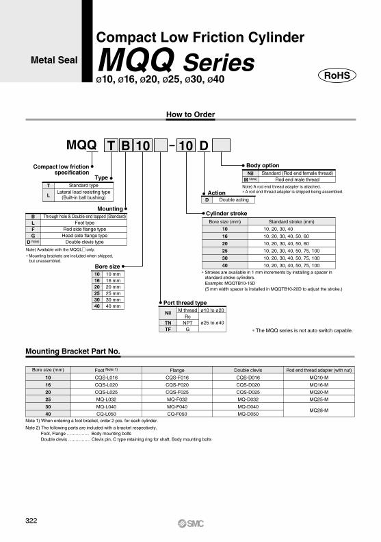
Cylinder stroke
Bore size101620253040
10 mm16 mm20 mm25 mm30 mm40 mm
Bore size (mm) Standard stroke (mm)
10, 20, 30, 40
10, 20, 30, 40, 50, 60
10, 20, 30, 40, 50, 60
10, 20, 30, 40, 50, 75, 100
10, 20, 30, 40, 50, 75, 100
10, 20, 30, 40, 50, 75, 100
10
16
20
25
30
40
CQS-L016
CQS-L020
CQS-L025
MQ-L032
MQ-L040
CQ-L050
CQS-F016
CQS-F020
CQS-F025
MQ-F032
MQ-F040
CQ-F050
MQ10-M
MQ16-M
MQ20-M
MQ25-M
MQ28-M
CQS-D016
CQS-D020
CQS-D025
MQ-D032
MQ-D040
MQ-D050
Port thread type
Nil
TNTF
M threadRc
NPTG
ø25 to ø40
ø10 to ø20
TypeT Standard type
Lateral load resisting type(Built-in ball bushing)L
MountingBLFG
D Note)
Through hole & Double end tapped (Standard)Foot type
Rod side flange typeHead side flange type
Double clevis type
Note) Available with the MQQL only.
∗ Mounting brackets are included when shipped,but unassembled.
Note) A rod end thread adapter is attached.∗ A rod end thread adapter is shipped being assembled.
Body optionNil
M Note)
Standard (Rod end female thread)Rod end male thread
D Double actingAction
∗ Strokes are available in 1 mm increments by installing a spacer in standard stroke cylinders.Example: MQQTB10-15D(5 mm width spacer is installed in MQQTB10-20D to adjust the stroke.)
Bore size (mm) Foot Note 1) Flange Rod end thread adapter (with nut)Double clevis
Note 1) When ordering a foot bracket, order 2 pcs. for each cylinder.
Note 2) The following parts are included with a bracket respectively.Foot, Flange …………… Body mounting boltsDouble clevis …………… Clevis pin, C type retaining ring for shaft, Body mounting bolts
∗ The MQQ series is not auto switch capable.
MQQ T B 10 10 D
Compact Low Friction Cylinder
MQQ Seriesø10, ø16, ø20, ø25, ø30, ø40
Metal Seal
How to Order
Mounting Bracket Part No.
322
INOUT
Compact Low Friction CylinderMetal Seal MQQ Series
SymbolDouble acting, Single rod
101620253040
40 166 286 414 671 7431082
30142246352579655964
20118206290487567846
10 94166228395479728
50—
326 476 763 8311200
60—
366538———
75———
99310521495
100———
122312721790
101620253040
40 220 404 569 82811751691
30 196 364 507 73610871573
20 172 324 445 644 9991455
10 148 284 383 552 9111337
50—
444 631 92012631809
60—
484693———
75———
115014852104
100———
138017052399
Weight: Standard Type/MQQT
Weight: Lateral Load Resisting Type/ MQQL (Built-in Ball Bushing)
Boresize(mm)
Unit: g
∗ Refer to page 340 for moving parts mass.
Cylinder stroke (mm)
Boresize(mm)
Unit: g
Cylinder stroke (mm)
10
20
25
30
40
50.3
78.5
145.8
196.1
235.6
314.2
377.8
490.9
505.8
706.9
1055.6
1256.6
0.1
6
8
10
12
16
IN
OUT
IN
OUT
IN
OUT
IN
OUT
IN
OUT
IN
OUT
5.0
7.9
14.9
19.6
23.6
31.4
37.8
49.1
50.6
70.7
105.6
125.7
0.2
10.1
15.7
29.2
39.2
47.1
62.8
75.6
98.2
101.2
141.4
211.2
251.4
0.3
15.1
23.6
43.7
58.9
70.7
94.3
113.3
147.3
151.8
212.1
316.8
377.1
0.4
20.1
31.4
58.3
78.4
94.2
125.7
151.1
196.4
202.4
282.8
422.4
502.8
0.5
25.2
39.3
72.9
98.1
117.8
157.1
188.9
245.5
253.0
353.5
528.0
628.5
0.6
30.2
47.1
87.5
117.7
141.4
188.5
226.7
294.5
303.6
424.2
633.6
754.2
0.7
35.2
55.0
102.1
137.3
164.9
219.9
262.5
343.6
354.2
494.9
739.2
879.9
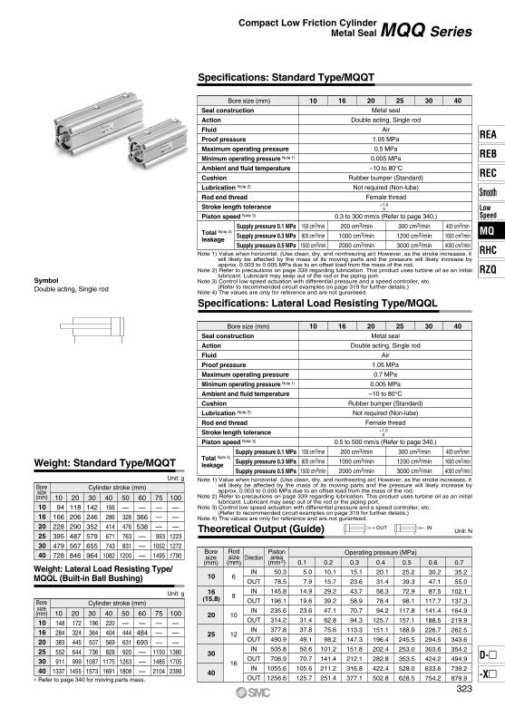
Unit: NTheoretical Output (Guide)
Boresize(mm)
Operating pressure (MPa)Rodsize(mm)
DirectionPistonarea
(mm2)
400 cm3/min
1600 cm3/min
4000 cm3/min
Bore size (mm)
Seal construction
Action
Fluid
Proof pressure
Maximum operating pressure
Minimum operating pressure Note 1)
Ambient and fluid temperature
Cushion
Lubrication Note 2)
Rod end thread
Stroke length tolerance
Piston speed Note 3)
Metal seal
Double acting, Single rod
Air
1.05 MPa
0.7 MPa
0.005 MPa
–10 to 80°CRubber bumper (Standard)
Not required (Non-lube)
Female thread
0.5 to 500 mm/s (Refer to page 340.)
10 16 20 25 30 40
150 cm3/min
800 cm3/min
1500 cm3/min
200 cm3/min
1000 cm3/min
2000 cm3/min
300 cm3/min
1200 cm3/min
3000 cm3/min
+1.00
Supply pressure 0.1 MPa
Supply pressure 0.3 MPa
Supply pressure 0.5 MPaNote 1) Value when horizontal. (Use clean, dry, and nonfreezing air) However, as the stroke increases, it
will likely be affected by the mass of its moving parts and the pressure will likely increase by approx. 0.003 to 0.005 MPa due to an offset load from the mass of the rod.
Note 2) Refer to precautions on page 339 regarding lubrication. This product uses turbine oil as an initial lubricant. Lubricant may seep out of the rod or the piping port.
Note 3) Control low speed actuation with differential pressure and a speed controller, etc.(Refer to recommended circuit examples on page 319 for further details.)
Note 4) The values are only for reference and are not guranteed.
Specifications: Lateral Load Resisting Type/MQQL
Bore size (mm)
Seal construction
Action
Fluid
Proof pressure
Maximum operating pressure
Minimum operating pressure Note 1)
Ambient and fluid temperature
Cushion
Lubrication Note 2)
Rod end thread
Stroke length tolerance
Piston speed Note 3)
Metal seal
Double acting, Single rod
Air
1.05 MPa
0.5 MPa
0.005 MPa
–10 to 80°CRubber bumper (Standard)
Not required (Non-lube)
Female thread
0.3 to 300 mm/s (Refer to page 340.)
10 16 20 25 30 40
150 cm3/min
800 cm3/min
1500 cm3/min
200 cm3/min
1000 cm3/min
2000 cm3/min
300 cm3/min
1200 cm3/min
3000 cm3/min
400 cm3/min
1600 cm3/min
4000 cm3/min
+1.00
Supply pressure 0.1 MPa
Supply pressure 0.3 MPa
Supply pressure 0.5 MPaNote 1) Value when horizontal. (Use clean, dry, and nonfreezing air) However, as the stroke increases, it
will likely be affected by the mass of its moving parts and the pressure will likely increase by approx. 0.003 to 0.005 MPa due to an offset load from the mass of the rod.
Note 2) Refer to precautions on page 339 regarding lubrication. This product uses turbine oil as an initial lubricant. Lubricant may seep out of the rod or the piping port.
Note 3) Control low speed actuation with differential pressure and a speed controller, etc.(Refer to recommended circuit examples on page 319 for further details.)
Note 4) The values are only for reference and are not guranteed.
Specifications: Standard Type/MQQT
Total Note 4)
leakage
Total Note 4)
leakage
16(15.8)
323
REA
REB
REC
SmoothLowSpeed
MQ
RHC
RZQ
D-
-X
MQ
q
!1 !6 !2
u !4 y r t !3 e i o w !0 !5
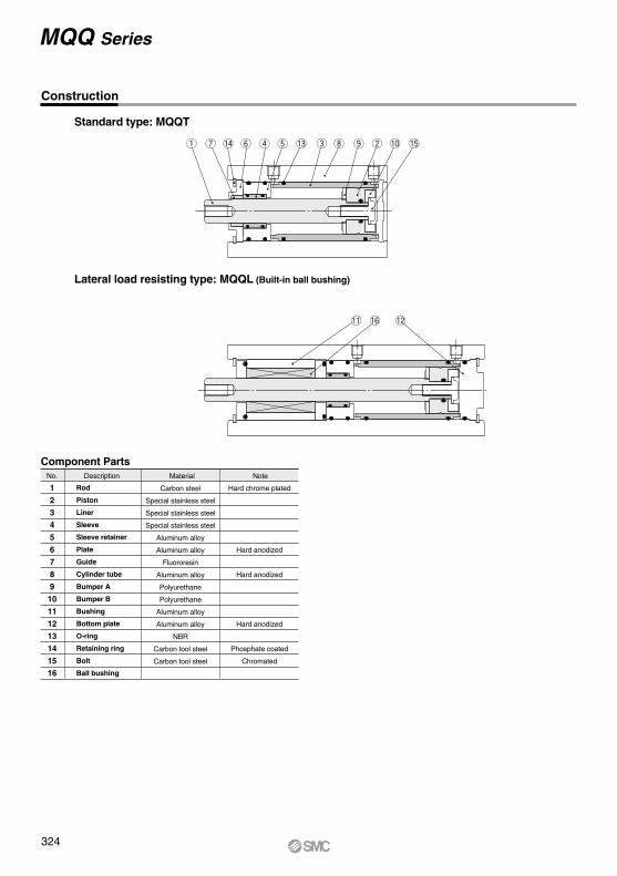
Standard type: MQQT
Lateral load resisting type: MQQL (Built-in ball bushing)
Construction
No.
1234567891011121314
1516
Description
Rod
Piston
Liner
Sleeve
Sleeve retainer
Plate
Guide
Cylinder tube
Bumper A
Bumper B
Bushing
Bottom plate
O-ring
Retaining ring
Bolt
Ball bushing
Carbon steel
Special stainless steel
Special stainless steel
Special stainless steel
Aluminum alloy
Aluminum alloy
Fluororesin
Aluminum alloy
Polyurethane
Polyurethane
Aluminum alloy
Aluminum alloy
NBR
Carbon tool steel
Carbon tool steel
Material Note
Component Parts
Hard chrome plated
Hard anodized
Hard anodized
Hard anodized
Phosphate coated
Chromated
MQQ Series
324
D D
EtE t
C C
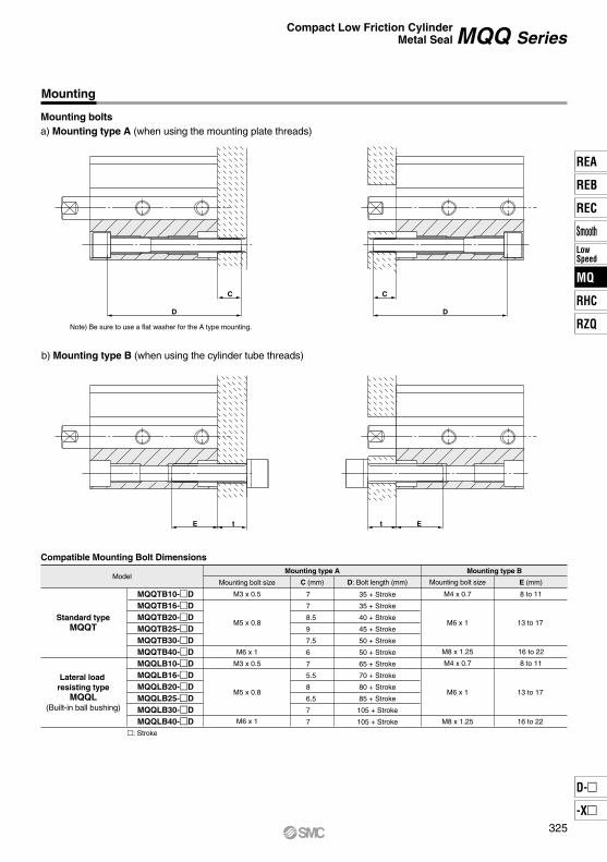
Mounting
Mounting boltsa) Mounting type A (when using the mounting plate threads)
Note) Be sure to use a flat washer for the A type mounting.
b) Mounting type B (when using the cylinder tube threads)
ModelMounting bolt size
M3 x 0.5
M5 x 0.8
M6 x 1
M3 x 0.5
M5 x 0.8
M6 x 1
Mounting bolt size
M6 x 1
M8 x 1.25
E (mm)
8 to 11
16 to 22
8 to 11
13 to 17
13 to 17
16 to 22
C (mm)
7
7
8.5
9
7.5
6
7
5.5
8
6.5
7
7
D: Bolt length (mm)
35 + Stroke
35 + Stroke
40 + Stroke
45 + Stroke
50 + Stroke
50 + Stroke
65 + Stroke
70 + Stroke
80 + Stroke
85 + Stroke
105 + Stroke
105 + Stroke
MQQTB10-DMQQTB16-DMQQTB20-DMQQTB25-DMQQTB30-DMQQTB40-DMQQLB10-DMQQLB16-DMQQLB20-DMQQLB25-DMQQLB30-DMQQLB40-D
Standard typeMQQT
Lateral load resisting type
MQQL(Built-in ball bushing)
: Stroke
M4 x 0.7
M6 x 1
M8 x 1.25
M4 x 0.7
Compatible Mounting Bolt DimensionsMounting type A Mounting type B
Compact Low Friction CylinderMetal Seal MQQ Series
325
REA
REB
REC
SmoothLowSpeed
MQ
RHC
RZQ
D-
-X
MQ
M
E±0.2
M
E
±0.2
QY F
A + Stroke
L B + StrokeK
øI
øD
X
C1
L1
øI
WEJ
M±0
.2
M ±0.2
E
K
øD
Y Q
2 x P
F
A + Stroke
B + StrokeL
2 x 4 x øOBDepth of counterbore RB
H effective thread depth C
2 x 4 x OA effective depth RA
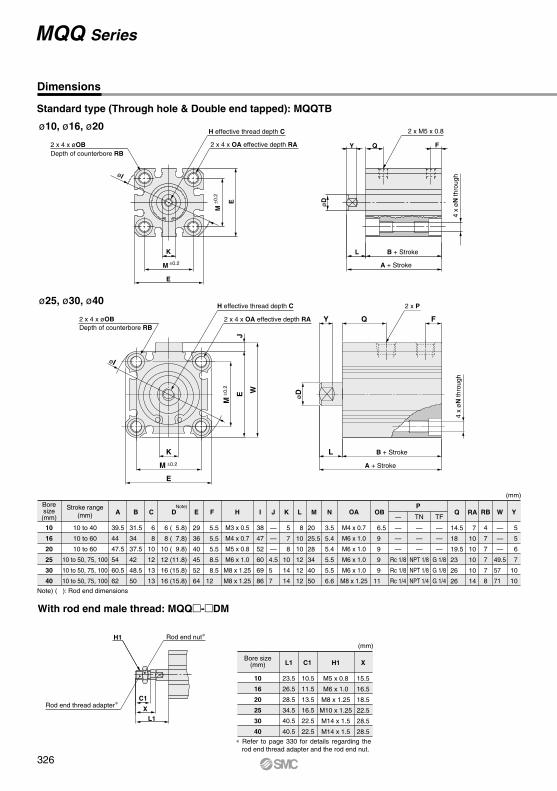
Dimensions
Standard type (Through hole & Double end tapped): MQQTB
ø10, ø16, ø20
2 x 4 x øOBDepth of counterbore RB
H effective thread depth C
2 x 4 x OA effective depth RA
2 x M5 x 0.8
4 x
øN
thro
ugh
4 x
øN
thro
ugh
Note) ( ): Rod end dimensions
(mm)
—
—
—
Rc 1/8
Rc 1/8
Rc 1/4
P
—
—
—
—
NPT 1/8
NPT 1/8
NPT 1/4
TN
—
—
—
G 1/8
G 1/8
G 1/4
TF
Boresize(mm)
Stroke range(mm)
10
16
20
25
30
40
10 to 40
10 to 60
10 to 60
10 to 50, 75, 100
10 to 50, 75, 100
10 to 50, 75, 100
39.5
44
47.5
54
60.5
62
A
31.5
34
37.5
42
48.5
50
B
6
8
10
12
13
13
C
6 ( 5.8)
8 ( 7.8)
10 ( 9.8)
12 (11.8)
16 (15.8)
16 (15.8)
D
29
36
40
45
52
64
E
5.5
5.5
5.5
8.5
8.5
12
F
M3 x 0.5
M4 x 0.7
M5 x 0.8
M6 x 1.0
M8 x 1.25
M8 x 1.25
H
38
47
52
60
69
86
I
—
—
—
4.5
5
7
J
5
7
8
10
14
14
K
8
10
10
12
12
12
L
20
25.5
28
34
40
50
M
3.5
5.4
5.4
5.5
5.5
6.6
N
6.5
9
9
9
9
11
OB
14.5
18
19.5
23
26
26
Q
7
10
10
10
10
14
RA
—
—
—
49.5
57
71
W
5
5
6
7
10
10
Y
M4 x 0.7
M6 x 1.0
M6 x 1.0
M6 x 1.0
M6 x 1.0
M8 x 1.25
OA
4
7
7
7
7
8
RBNote)
With rod end male thread: MQQ-DM
Rod end nut∗
Rod end thread adapter∗
H1
Bore size(mm)
(mm)
10
16
20
25
30
40
23.5
26.5
28.5
34.5
40.5
40.5
L1
10.5
11.5
13.5
16.5
22.5
22.5
C1
M5 x 0.8
M6 x 1.0
M8 x 1.25
M10 x 1.25
M14 x 1.5
M14 x 1.5
H1
15.5
16.5
18.5
22.5
28.5
28.5
X
∗ Refer to page 330 for details regarding the rod end thread adapter and the rod end nut.
ø25, ø30, ø40
MQQ Series
326
MQQ Series
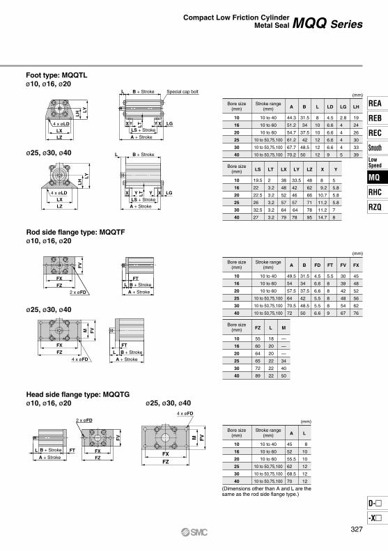
Foot type: MQQTLø10, ø16, ø20
Rod side flange type: MQQTFø10, ø16, ø20
ø25, ø30, ø40
Head side flange type: MQQTGø10, ø16, ø20 ø25, ø30, ø40
ø25, ø30, ø40
Bore size(mm)
Stroke range(mm)
(mm)
10
16
20
25
30
40
10 to 40
10 to 60
10 to 60
10 to 50,75,100
10 to 50,75,100
10 to 50,75,100
44.3
51.2
54.7
61.2
67.7
70.2
A
31.5
34
37.5
42
48.5
50
B
8
10
10
12
12
12
L
4.5
6.6
6.6
6.6
6.6
9
LD
2.8
4
4
4
4
5
LG
19
24
26
30
33
39
LH
Bore size(mm)
10
16
20
25
30
40
19.5
22
22.5
26
32.5
27
LS
2
3.2
3.2
3.2
3.2
3.2
LT
38
48
52
57
64
79
LX
33.5
42
46
57
64
78
LY
48
62
66
71
78
95
LZ
8
9.2
10.7
11.2
11.2
14.7
X
5
5.8
5.8
5.8
7
8
Y
Bore size(mm)
Stroke range(mm)
(mm)
10
16
20
25
30
40
10 to 40
10 to 60
10 to 60
10 to 50,75,100
10 to 50,75,100
10 to 50,75,100
49.5
54
57.5
64
70.5
72
A
31.5
34
37.5
42
48.5
50
B
4.5
6.6
6.6
5.5
5.5
6.6
FD
5.5
8
8
8
8
9
FT
30
39
42
48
54
67
FV
45
48
52
56
62
76
FX
Bore size(mm)
Stroke range(mm)
(mm)
10
16
20
25
30
40
10 to 40
10 to 60
10 to 60
10 to 50,75,100
10 to 50,75,100
10 to 50,75,100
45
52
55.5
62
68.5
70
A
8
10
10
12
12
12
L
Bore size(mm)
10
16
20
25
30
40
55
60
64
65
72
89
FZ
18
20
20
22
22
22
L
—
—
—
34
40
50
M
(Dimensions other than A and L are thesame as the rod side flange type.)
Compact Low Friction CylinderMetal Seal
Special cap boltB + Stroke
A + Stroke
4 x øLD X X LGLS + Stroke
Y Y
L
LXLZ
LT
LH L
Y
FTL B + Stroke
A + Stroke2 x øFD
FX
FZ
FV
L FT FXFZ
B + Stroke
A + Stroke
2 x øFD
FV
LZLX
4 x øLD
LY
LH
B + StrokeL
A + Stroke
LS + Stroke
LTYX LGXY
FZ
FX
4 x øFD
FVM
A + Stroke
B + StrokeL
FT
FVM
FZ
FX
4 x øFD
327
REA
REB
REC
SmoothLowSpeed
MQ
RHC
RZQ
D-
-X
MQ
Dimensions
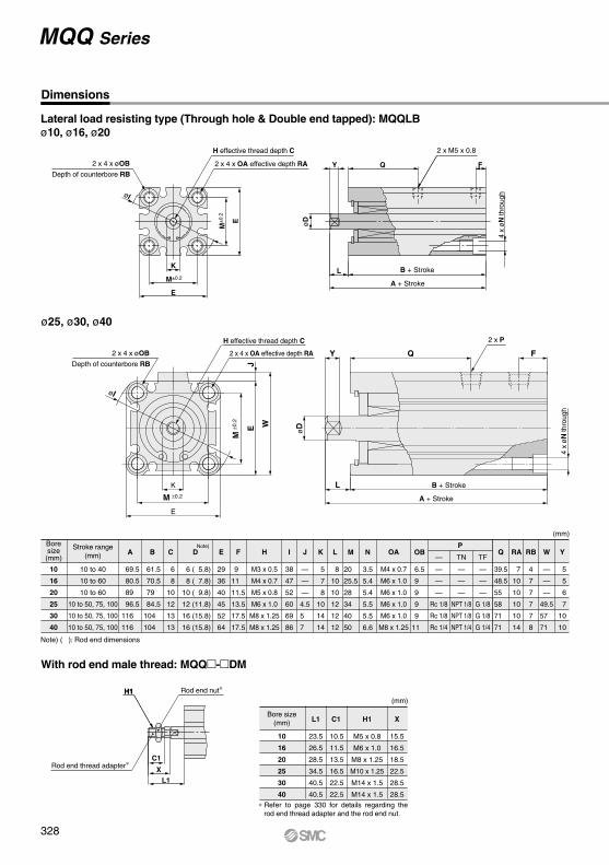
Lateral load resisting type (Through hole & Double end tapped): MQQLBø10, ø16, ø20
Note) ( ): Rod end dimensions
(mm)
—
—
—
Rc 1/8
Rc 1/8
Rc 1/4
P
—
—
—
—
NPT 1/8
NPT 1/8
NPT 1/4
TN
—
—
—
G 1/8
G 1/8
G 1/4
TF
Boresize(mm)
Stroke range(mm)
10
16
20
25
30
40
10 to 40
10 to 60
10 to 60
10 to 50, 75, 100
10 to 50, 75, 100
10 to 50, 75, 100
69.5
80.5
89
96.5
116
116
A
61.5
70.5
79
84.5
104
104
B
6
8
10
12
13
13
C
6 ( 5.8)
8 ( 7.8)
10 ( 9.8)
12 (11.8)
16 (15.8)
16 (15.8)
D
29
36
40
45
52
64
E
9
11
11.5
13.5
17.5
17.5
F
M3 x 0.5
M4 x 0.7
M5 x 0.8
M6 x 1.0
M8 x 1.25
M8 x 1.25
H
38
47
52
60
69
86
I
—
—
—
4.5
5
7
J
5
7
8
10
14
14
K
8
10
10
12
12
12
L
20
25.5
28
34
40
50
M
3.5
5.4
5.4
5.5
5.5
6.6
N
6.5
9
9
9
9
11
OB
39.5
48.5
55
58
71
71
Q
7
10
10
10
10
14
RA
—
—
—
49.5
57
71
W
5
5
6
7
10
10
Y
M4 x 0.7
M6 x 1.0
M6 x 1.0
M6 x 1.0
M6 x 1.0
M8 x 1.25
OA
4
7
7
7
7
8
RBNote)
With rod end male thread: MQQ-DM
Bore size(mm)
(mm)
10
16
20
25
30
40
23.5
26.5
28.5
34.5
40.5
40.5
L1
10.5
11.5
13.5
16.5
22.5
22.5
C1
M5 x 0.8
M6 x 1.0
M8 x 1.25
M10 x 1.25
M14 x 1.5
M14 x 1.5
H1
15.5
16.5
18.5
22.5
28.5
28.5
X
ø25, ø30, ø40
MQQ Series
B + Stroke
A + Stroke
Y Q
L
F
4 x
øN
thro
ugh
K
E
E øD
M±
0.2
M±0.2
øI
X
C1
L1
øI
WEJ
M±0
.2
M ±0.2
E
K
øD
Y Q F
4 x
øN
thro
ugh
A + Stroke
B + StrokeL
H1
2 x M5 x 0.8
2 x P
Rod end nut∗H1
2 x 4 x øOB
Depth of counterbore RB
2 x 4 x øOB
Depth of counterbore RB
H effective thread depth C
2 x 4 x OA effective depth RA
H effective thread depth C
2 x 4 x OA effective depth RA
Rod end thread adapter∗
∗ Refer to page 330 for details regarding the rod end thread adapter and the rod end nut.
328
MQQ Series
Bore size(mm)
Stroke range(mm)
(mm)
10
16
20
25
30
40
10 to 40
10 to 60
10 to 60
10 to 50,75,100
10 to 50,75,100
10 to 50,75,100
74.3
87.7
96.2
103.7
123.2
124.2
A
61.5
70.5
79
84.5
104
104
B
8
10
10
12
12
12
L
4.5
6.6
6.6
6.6
6.6
9
LD
2.8
4
4
4
4
5
LG
19
24
26
30
33
39
LH
Bore size(mm)
10
16
20
25
30
40
49.5
58.5
64
68.5
88
81
LS
2
3.2
3.2
3.2
3.2
3.2
LT
38
48
52
57
64
79
LX
33.5
42
46
57
64
78
LY
48
62
66
71
78
95
LZ
8
9.2
10.7
11.2
11.2
14.7
X
5
5.8
5.8
5.8
7
8
Y
Bore size(mm)
Stroke range(mm)
(mm)
10
16
20
25
30
40
10 to 40
10 to 60
10 to 60
10 to 50,75,100
10 to 50,75,100
10 to 50,75,100
90.5
107.5
119
126.5
148
158
A
61.5
70.5
79
84.5
104
104
B
5
8
10
10
10
14
CD
84.5
98.5
109
116.5
138
144
CL
4
5
5
5
6
7
CT
10
12
14
14
14
20
CU
Bore size(mm)
10
16
20
25
30
40
15
18
20
20
22
28
CW
6.5
8
10
18
18
22
CX
12
16
20
36
36
44
CZ
8
10
10
12
12
12
L
6
9
10
10
10
14
RR
Bore size(mm)
Stroke range(mm)
(mm)
10
16
20
25
30
40
10 to 40
10 to 60
10 to 60
10 to 50,75,100
10 to 50,75,100
10 to 50,75,100
75
88.5
97
104.5
124
124
A
8
10
10
12
12
12
L
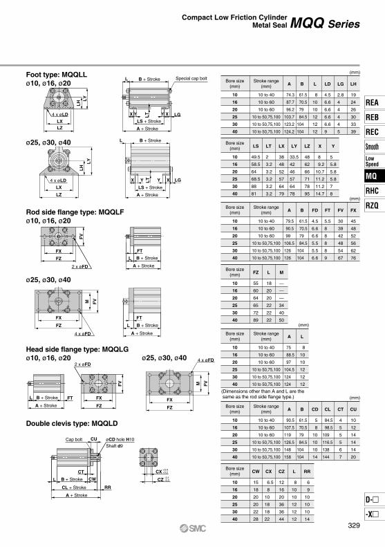
(Dimensions other than A and L are the same as the rod side flange type.)
Bore size(mm)
Stroke range(mm)
(mm)
10
16
20
25
30
40
10 to 40
10 to 60
10 to 60
10 to 50,75,100
10 to 50,75,100
10 to 50,75,100
79.5
90.5
99
106.5
126
126
A
61.5
70.5
79
84.5
104
104
B
4.5
6.6
6.6
5.5
5.5
6.6
FD
5.5
8
8
8
8
9
FT
30
39
42
48
54
67
FV
45
48
52
56
62
76
FX
Bore size(mm)
10
16
20
25
30
40
55
60
64
65
72
89
FZ
18
20
20
22
22
22
L
—
—
—
34
40
50
M
Foot type: MQQLLø10, ø16, ø20
Rod side flange type: MQQLFø10, ø16, ø20
ø25, ø30, ø40
ø25, ø30, ø40
CX
CZ
+0.4+0.2
-0.1-0.3B + Stroke
A + Stroke
CL + Stroke
øCD hole H10Shaft d9
Cap bolt
Special cap bolt
4 x øLD
B + Stroke
A + Stroke
LS + Stroke
B + Stroke
A + Stroke2 x øFD
B + Stroke
A + Stroke
B + Stroke
A + Stroke
4 x øFD
2 x øFD4 x øFD
4 x øLD
Head side flange type: MQQLGø10, ø16, ø20 ø25, ø30, ø40
Double clevis type: MQQLD
Compact Low Friction CylinderMetal Seal
X X LGY Y
L
LXLZ
LT
LH L
Y
FT
L
FX
FZ
FV
L FT FX
FZ
FV
L
CT
CW
RR
CU
LZ
LX
LY
LH
B + StrokeL
A + Stroke
LS + Stroke
LTX Y Y X LG
FZ
FX
FVM
FT
L
FZ
FX
FVM
329
REA
REB
REC
SmoothLowSpeed
MQ
RHC
RZQ
D-
-X
MQ
Clevis pin
Part no. A
MQ10-MMQ16-MMQ20-MMQ25-MMQ28-M
Applicable boresize (mm)
10
16
20
25
30, 40
20.5
22.5
24.5
33.5
40.5
B
8
8
8
10
14
C
9.2
9.2
9.2
11.5
16
E
15.5
16.5
18.5
22.5
28.5
F
5
6
6
11
12
D
6
8
10
12
16
Rod
C
B
MM
ød
øD
d9
mm l
tLt
H
E F
AB H
C
dNN
øD
Part no. B
NTJ-015ANT-015A
NT-02NT-03NT-04
Applicable boresize (mm)
10
16
20
25
30, 40
8
10
13
17
22
C
9.2
11.5
15
19.6
25.4
d
M5 x 0.8
M6 x 1.0
M8 x 1.25
M10 x 1.25
M14 x 1.5
H
4
5
5
6
8
Weight
1.5 g
2.5 g
4.0 g
8.0 g
17.0 g
Part no. H
MQ10-MMQ16-MMQ20-MMQ25-MMQ28-M
Applicable boresize (mm)
10
16
20
25
30, 40
10.5
11.5
13.5
16.5
22.5
MM
M5 x 0.8
M6 x 1.0
M8 x 1.25
M10 x 1.25
M14 x 1.5
NN
M3 x 0.5
M4 x 0.7
M5 x 0.8
M6 x 1.0
M8 x 1.25
Weight Note)
5.5 g
7.5 g
11.5 g
22.5 g
52.0 g
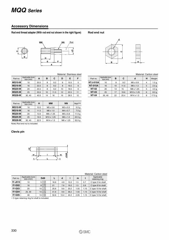
∗ C-type retaining ring for shaft is included.
MQQ Series
Accessory Dimensions
Rod end thread adapter (With rod end nut shown in the right figure) Rod end nut
Part no. Dd9
IY-J015IY-G02IY-G03IY-G04IY-G05
Applicable boresize (mm)
Applicableretaining ring
10
16
20
25, 30
40
5
8
10
10
14
L
16.6
21
25.6
41.6
50.6
l
12.2
16.2
20.2
36.2
44.2
m
1.5
1.5
1.55
1.55
2.05
d
4.8
7.6
9.6
9.6
13.4
C type 5 for shaft
C type 8 for shaft
C type 10 for shaft
C type 10 for shaft
C type 14 for shaft
t
0.7
0.9
1.15
1.15
1.15
-0.030-0.040-0.040-0.076-0.040-0.076-0.040-0.076-0.050-0.093
Note) Rod end nut is included
Material: Carbon steelMaterial: Stainless steel
Material: Carbon steel
330
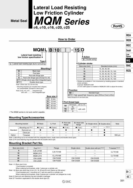
Bore size (mm)
6
10
16
20
25
Foot Note 1)
CJK-L016B
MQM-L010
MQM-L016
CM-L020B
CM-L032B
Flange
CJK-F016B
CLJ-F016B
CM-F020B
CM-F032B
Single clevis
—
—
—
CM-C020B
CM-C032B
Double clevis (with pin) Note 2)
—
—
—
CM-D020B
CM-D032B
T-bracket Note 3)
CJ-T010B
CJ-T016B
—
—
Mounting
Type
6
10
16
20
25
BLFG
C Note 1)
D Note 2)
Basic typeFoot type
Rod side flange typeHead side flange type (Except for ø6)
Single clevis type (Non-integrated type)Double clevis type
Note 1) Bore size: 20, 25 mm only
∗ Mounting brackets are included when shipped,but unassembled. (Except for clevis type.)
Note 2) ø6, ø10, ø16 ...... Integrated type ø20, ø25 ............ Non-integrated type
L Lateral load resisting type (Built-in ball bushing)
D Double acting
Bore size 610162025
6 mm10 mm16 mm20 mm25 mm
Cylinder stroke
Action
Port thread type
Nil M threadRc
NPTG
ø6 to ø16
ø20, ø25
Bore size (mm) Standard stroke (mm)
15, 30, 45, 60
15, 30, 45, 60, 75, 100
15, 30, 45, 60, 75, 100
15, 30, 45, 60, 75, 100
15, 30, 45, 60, 75, 100
TNTF
Mounting Type/Accessories
∗ The MQM series is not auto switch capable.
Lateral load resistinglow friction specification
∗ Strokes are available in 1mm increments by installing spacers in standard stroke cylinders.Example: MQMLB10-20D(10 mm width spacer is installed in MQMLB10-30D to adjust the stroke.)
Note) Except for 6 mm bore size.
FunctionNil
H Note)
Standard typeHigh speed/High frequency type (Without fixed orifice)
Mounting bracket B: Basic
(1 pc.)
—
—
(2 pcs.)
—
—
(1 pc.)
—
—
(1 pc.)
—
—
—
—
—
—
With pin
L: Foot NoteF: Rod side
flangeG: Head side
flange C: Single clevis D: Double clevis
Standard
Mounting nut Note 1)
Rod end nut
Clevis pin
T-bracketOption
Note 1) Mounting nut is not included with the integrated clevis, single clevis and double clevis types.Note 2) Pin and retaining ring are packed with the double clevis type.
Note 2)Note 1)
Mounting Bracket Part No.
Note 1-1) Bore size 6 mm:1 foot bracket is included.When ordering foot brackets, order 1 piece per a cylinder unit.
Note 1-2) Bore size other than 6 mm (10, 16, 20 and 25 mm) (Same as CM series):2 foot brackets and 1 mounting nut (1 set) are used for a cylinder unit.When ordering foot brackets, order 2 pieces per a cylinder unit (shipped as a set).
Note 2) Clevis pin and retaining ring are included in package.Note 3) T-bracket is applicable to the double clevis type (D).
MQML DB 10 15
Lateral Load ResistingLow Friction Cylinder
MQM Seriesø6, ø10, ø16, ø20, ø25
Metal Seal
How to Order
RoHS
331
REA
REB
REC
SmoothLowSpeed
MQ
RHC
RZQ
D-
-X
MQ
15.7
28.3
66.0
78.5
176.4
196.1
263.9
314.2
412.3
490.9
1.6
2.8
6.6
7.9
17.6
19.6
26.4
31.4
41.2
49.1
3.2
5.7
13.2
15.7
35.3
39.2
52.8
62.8
82.5
98.2
4.7
8.5
19.8
23.6
52.9
58.9
79.2
94.3
123.7
147.3
6.3
11.3
26.4
31.4
70.6
78.4
105.6
125.7
164.9
196.4
7.9
14.2
33.0
39.3
88.2
98.1
132.0
157.1
206.2
245.5
9.4
17.0
39.6
47.1
105.8
117.8
158.3
188.5
247.4
294.5
11.0
19.8
46.2
55.0
123.5
137.3
184.7
219.9
288.6
343.6
INOUT
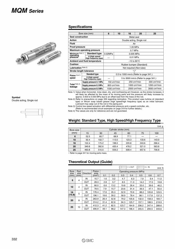
MQM Series
SymbolDouble acting, Single rod
Weight: Standard Type, High Speed/High Frequency Type
Theoretical Output (Guide)
Bore size(mm)
Unit: g
∗ Refer to page 341 for moving parts mass.
Cylinder stroke (mm)
610162025
77.1
123.3
220.8
478.2
608.4
60 68.9
113.0
198.0
435.4
559.2
45 60.7
102.7
175.2
392.6
510.0
30 52.5
92.4
152.4
349.8
460.8
15—
133.6
243.6
521.0
657.6
75—
143.9
266.4
563.8
706.8
100
Boresize(mm)
6
10
20
25
Operating pressure (MPa)
0.1
Rod size(mm)
4
4
5
8
10
Direction
IN
OUT
IN
OUT
IN
OUT
IN
OUT
IN
OUT
Piston area(mm2) 0.2 0.3 0.4 0.5 0.6 0.7
Unit: N
Specifications
Bore size (mm)
Seal construction
Action
Fluid
Proof pressureMaximum operating pressure
Minimum Note 1)
operatingpressure
Ambient and fluid temperatureCushion
Lubrication Note 2)
Stroke length tolerance
Piston Note 3)
speed
Metal seal
Double acting, Single rod
Air
1.05 MPa
0.7 MPa
0.005 MPa
0.01 MPa
-10 to 80°CRubber bumper (Standard)
Not required (Non-lube)
0.5 to 1000 mm/s (Refer to page 341.)
6 10 16 20 25
300 cm3/min
1200 cm3/min
3000 cm3/min
150 cm3/min
800 cm3/min
1500 cm3/min
250 cm3/min
1000 cm3/min
2500 cm3/min
+1.00
Standard typeH (High speed/
High frequency type)
Supply pressure 0.1 MPa
Supply pressure 0.3 MPa
Supply pressure 0.5 MPa
Standard typeH (High speed/
High frequency type)
0.02MPa
—
— 5 to 3000 mm/s (Refer to page 341.)
Note 1) Value when horizontal. (Use clean, dry, and nonfreezing air) However, as the stroke increases, it will likely be affected by the mass of its moving parts and the pressure will likely increase by approx. 0.003 to 0.005 MPa due to an offset load from the mass of the rod.
Note 2) Refer to precautions on page 339 regarding lubrication. This product uses turbine oil (standard type) or lithium soap based grease (high speed/high frequency type) as an initial lubricant. Lubricant may seep out of the rod or the piping port.
Note 3) Control low speed actuation with differential pressure and a speed controller, etc.(Refer to recommended circuit examples on page 319 for further details.)
Note 4) The values are only for reference and are not guranteed.
16(15.8)
Total Note 4)
leakage
332
q
u
!4 !6
y
rt
!5
e
i o
!3 w
!0 !1!2
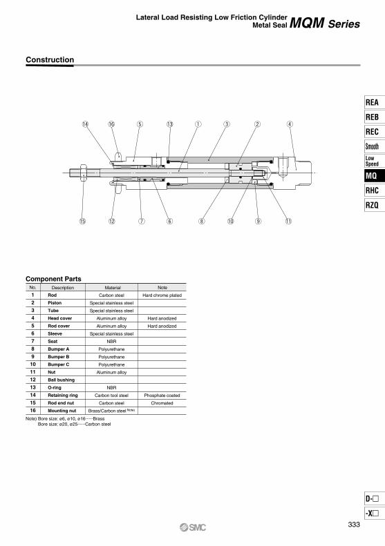
Note) Bore size: ø6, ø10, ø16......BrassBore size: ø20, ø25......Carbon steel
Lateral Load Resisting Low Friction CylinderMetal Seal MQM Series
Construction
No.
1234567891011121314
1516
Description
Rod
Piston
Tube
Head cover
Rod cover
Sleeve
Seat
Bumper A
Bumper B
Bumper C
Nut
Ball bushing
O-ring
Retaining ring
Rod end nut
Mounting nut
Carbon steel
Special stainless steel
Special stainless steel
Aluminum alloy
Aluminum alloy
Special stainless steel
NBR
Polyurethane
Polyurethane
Polyurethane
Aluminum alloy
NBR
Carbon tool steel
Carbon steel
Brass/Carbon steel Note)
Material Note
Component Parts
Hard chrome plated
Hard anodized
Hard anodized
Phosphate coated
Chromated
333
REA
REB
REC
SmoothLowSpeed
MQ
RHC
RZQ
D-
-X
MQ
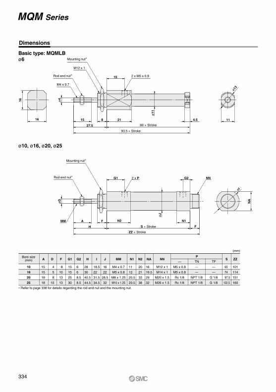
MQM Series
Basic type: MQMLBø6
Dimensions
ø10, ø16, ø20, ø25
∗ Refer to page 338 for details regarding the rod end nut and the mounting nut.
Bore size(mm)
(mm)
10
16
20
25
15
15
18
18
A
4
5
8
10
D
8
10
13
13
F
15
15
25
30
G1
6
6
8.5
8.5
G2
18.5
22
31.5
34.5
I
28
30
40.5
44.5
H
16
22
28.5
32
J
11
12
20.5
20.5
N1
20
21
33
38
N2
16
19.5
29
32
NA
65
74
97.5
102.5
S
M12 x 1
M14 x 1
M20 x 1.5
M26 x 1.5
NN
M5 x 0.8
M5 x 0.8
Rc 1/8
Rc 1/8
—
—
NPT 1/8
NPT 1/8
—
—
G 1/8
G 1/8
P
TN— TF
M4 x 0.7
M5 x 0.8
M8 x 1.25
M10 x 1.25
MM
101
114
151
160
ZZ
66 + Stroke
93.5 + Stroke
15
ø11
16 15 8
27.5
21 4.5 11
ø4
ø13
S + Stroke
ZZ + Stroke
G1 G2
øJ
A F
H
N2 N1
F
NA
øD
øI
16
NN
MM
Rod end nut∗
Mounting nut∗
M12 x 1
2 x M5 x 0.8
M4 x 0.7
Rod end nut∗ 2 x P
Mounting nut∗
334
Lateral Load Resisting Low Friction CylinderMetal Seal MQM Series
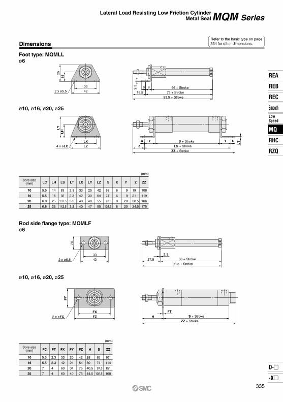
Foot type: MQMLLø6
DimensionsRefer to the basic type on page334 for other dimensions.
ø10, ø16, ø20, ø25
Rod side flange type: MQMLFø6
ø10, ø16, ø20, ø25
Bore size(mm)
(mm)
10
16
20
25
5.5
5.5
6.8
6.8
LC
14
18
25
28
LH
83
92
137.5
142.5
LS
2.3
2.3
3.2
3.2
LT
33
42
40
40
LX
25
30
40
47
LY
6
6
8
8
X
65
74
97.5
102.5
S
42
54
55
55
LZ
9
9
20
20
Y
19
21
20.5
24.5
Z
108
119
166
175
ZZ
Bore size(mm)
(mm)
10
16
20
25
5.5
5.5
7
7
FC
2.3
2.3
4
4
FT
33
42
60
60
FX
20
24
34
40
FY
42
54
75
75
FZ
28
30
40.5
44.5
H
101
114
151
160
ZZ
65
74
97.5
102.5
S
2 x ø5.5
4 x øLC
2 x ø5.5
2 x øFC
66 + Stroke75 + Stroke
93.5 + Stroke
S + StrokeLS + Stroke
ZZ + Stroke
66 + Stroke93.5 + Stroke
S + StrokeZZ + Stroke
3342 18.5
6 92.3
2514
LXLZ Z
X XY Y
LT
LY
LH
3342 27.5
2.3
20
FXFZ H
FT
FY
335
REA
REB
REC
SmoothLowSpeed
MQ
RHC
RZQ
D-
-X
MQ
H
FT FX
FZ
FY
H 30
14
9
øC
I
MQM Series
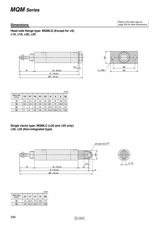
Head side flange type: MQMLG (Except for ø6)ø10, ø16, ø20, ø25
DimensionsRefer to the basic type on page 334 for other dimensions.
Bore size(mm)
(mm)
10
16
20
25
5.5
5.5
7
7
FC
2.3
2.3
4
4
FT
33
42
60
60
FX
20
24
34
40
FY
42
54
75
75
FZ
28
30
40.5
44.5
H
101
114
151
160
ZZ
95.3
106.3
142
151
Z
65
74
97.5
102.5
S
Single clevis type: MQMLC (ø20 and ø25 only)ø20, ø25 (Non-integrated type)
Bore size(mm)
(mm)
20
25
24
30
CI
40.5
44.5
H
97.5
102.5
S
168
177
Z
177
186
ZZ
S + Stroke 2 x øFC
Z + Stroke
ZZ + Stroke
S + Stroke
ø9 hole H10
Z + Stroke
ZZ + Stroke
10-0.1-0.2
+0.058 0
336
Dimensions
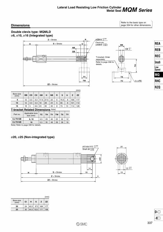
Double clevis type: MQMLDø6, ø10, ø16 (Integrated type)
Refer to the basic type on page 334 for other dimensions.
Lateral Load Resisting Low Friction CylinderMetal Seal MQM Series
Bore size(mm)
(mm)
6
10
16
12
12
18
BB
3.3
3.3
5
CD
3.3
3.3
6.6
CX
17.5
19
24
GB
27.5
28
30
H
22
24
30
NB
8
8
10
U
106
101
114
Z
117
112
128
ZZ
70.5
65
74
S
5
5
8
R
Applicable boresize (mm)
Part no.
T-bracket Related Dimensions Note)
Note) Refer to page 338 for details.
6, 10
16
4.5
5.5
TC
29
35
TH
40
48
TV
22
28
TW
32
38
TX
12
16
TY
CJ-T010B
CJ-T016B
ø20, ø25 (Non-integrated type)
Bore size(mm)
(mm)
20
25
24
30
CI
40.5
44.5
H
97.5
102.5
S
168
177
Z
177
186
ZZ
øCDH9
Clevis pin(øCDd9 )
T-bracket: Orderseparately. Refer to page 338 fordetails.
+0.030 0
-0.030-0.060
+0.058 0
-0.040-0.076
ø9 hole H10Shaft d9
BBH
R
U
NB
GB
TY TX
TVTW
TH
CX
S + Stroke
2 x øTC
Z + Stroke
ZZ + Stroke
+0.1 0
S + Stroke
øC
I
25
10
1930
9
14
Z + Stroke
ZZ + Stroke
H
+0.2+0.1
337
REA
REB
REC
SmoothLowSpeed
MQ
RHC
RZQ
D-
-X
MQ
Part no. MaterialBApplicable boresize (mm)
6, 10
16
20
25
17
19
26
32
C
19.6
21.9
30
37
d
M12 x 1
M14 x 1
M20 x 1.5
M26 x 1.5
H
4
5
8
8
Brass
Brass
Carbon steel
Carbon steel
12
TH7
TK
L
l
t tm m
øD
d9
ød
TX
TV
TT TY
TW
B H
C
d
B H
C
d
SNKJ-016BSNLJ-016B
SN-020BSN-032B
Stainless steel
Stainless steel
Carbon steel
Material
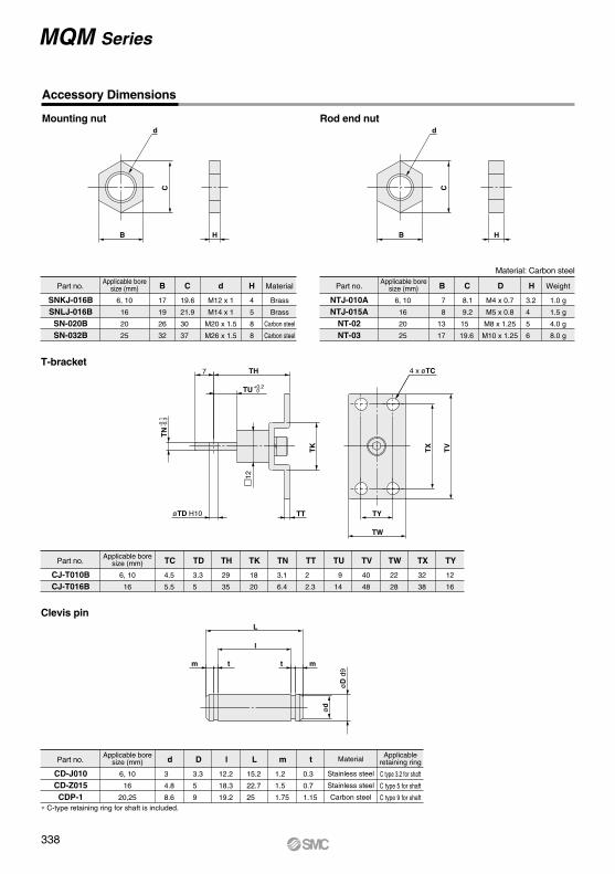
MQM Series
Accessory Dimensions
Mounting nut Rod end nut
Part no. B
NTJ-010ANTJ-015A
NT-02NT-03
Part no. TCApplicable boresize (mm)
6, 10
16
4.5
5.5
TD
3.3
5
TH
29
35
TK
18
20
TN
3.1
6.4
TT
2
2.3
TU
9
14
TV
40
48
TW
22
28
TX
32
38
TY
12
16
CJ-T010BCJ-T016B
Part no. dApplicable boresize (mm)
6, 10
16
20,25
3
4.8
8.6
D
3.3
5
9
l
12.2
18.3
19.2
L
15.2
22.7
25
m
1.2
1.5
1.75
t
0.3
0.7
1.15
CD-J010CD-Z015CDP-1
Applicable boresize (mm)
6, 10
16
20
25
7
8
13
17
C
8.1
9.2
15
19.6
D
M4 x 0.7
M5 x 0.8
M8 x 1.25
M10 x 1.25
H
3.2
4
5
6
Material: Carbon steel
T-bracket
Clevis pin
TU
TN
4 x øTC
øTD H10
+0.2 0
-0.1
-0.3
∗ C-type retaining ring for shaft is included.
Applicableretaining ring
C type 3.2 for shaft
C type 5 for shaft
C type 9 for shaft
Weight
1.0 g
1.5 g
4.0 g
8.0 g
338
MQQ/MQM SeriesSpecific Product Precautions 1
Operation Disassembly
Lubrication
Caution Caution
Caution
1. When mounting, thoroughly flush out the connector piping and be sure that dirt and chips, etc., do not get inside the cylinder.
2. Install an air filter with a filtration degree of 5 µm or less on the air supply. Furthermore, when controlling for low speed or controlled output, use clean air (atmospheric pressure dew point temperature of –10°C). Installation of a mist separator (filtration degree 0.3 µm or less) is also recommended.
3. Use a metal seal type when using solenoid valves for cylinder actuation. If a rubber seal type is used, there may be an increase in operating resistance due to grease sprayed from the main valve.
4. Operate so that the load applied to the piston rod is normally in the axial direction.In the event that a lateral load is unavoidable, do not exceed the range of the allowable lateral load at the rod end (refer to pages 340 and 341). (Use outside of the operating limits may cause an adverse effect on the life of the unit through problems such as looseness in the guide unit and a loss of precision.)
5. Take care not to scratch or gouge the sliding portion of the rod. This may cause malfunction or shorten the unit’s life.
6. When attaching a work piece to the end of the rod, move the rod to the fully retracted position and use the wrench flats at the end of the rod. Fasten the work piece without applying a large amount of torque to the rod.There are no wrench flats at the end of the rod in the MQM series, so use the attached rod end nut.
7. Be certain to connect a load so that the rod axis is aligned with the load and its direction of movement.Especially when a cylinder rod is connected directly to a guide function (such as bearings, etc.) on the equipment side, the following is likely to occur. Either an offset load will occur and the sliding resistance will not be stable or galling will occur on the metal seal parts. Therefore, be sure to use a floating joint or a spherical joint.
8. When a piston rod is driven with a circuit from an external force such as force, control, tension control, etc., a stick-slip phenomenon will likely occur and sliding resistance will not be stable if the amount of displacement is 0.05 mm or less.
9. When it is used in locations where a constant vibration is applied, such as a polishing machine, etc., consult with us.
1. The component parts of the metal seal cylinder are manufactured to precision tolerances, and therefore cannot be disassembled.
1. Lubrication of non-lube type cylinderDo not apply lubrication when controlling for low speed or controlled output. If lubrication is applied, there may be changes in operating resistance due to factors such as the viscosity and surface tension of the oil. Also, use a metal seal type when using solenoid valves for cylinder actuation. If a rubber seal type is used, there may be an increase in operating resistance due to grease sprayed from the main valve.Lubrication is also unnecessary for high speed actuation, but in the event that lubrication is applied, use turbine oil class 1 (with no additives) ISO VG32. (Do not use spindle oil or machine oil.)
Be sure to read this before handling the products.Refer to back page 50 for Safety Instructions and pages 3 to 12 for Actuator and Auto Switch Precautions.
339
REA
REB
REC
SmoothLowSpeed
MQ
RHC
RZQ
D-
-X
MQ
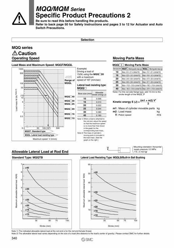
Note 1) The indicated allowable lateral load at the rod end is for the rod end female thread. Note 2) The allowable lateral load varies depending on the size of a load (the distance to the load's center of gravity). Please contact SMC for further details.
Moving Parts Mass
Selection
CautionOperating Speed
MQQ series
Load Mass and Maximum Speed: MQQT/MQQLExample)Driving a load of15(N) using the MQQ20with a maximumspeed of 167 (mm/sec)
Note 1) When a load is attached to the rod end, adjust the speed so that the maximum speed is no more than that shown in the graph for the corresponding load mass.
Note 2) The mass of cylinder’s moving parts is included in the load mass. (See the graph on the right.)
Lateral load resisting type: MQQ
Bore size (mm) Allowablekinetic energy (J)
101620253040
0.006
0.010
0.022
0.044
0.080
0.160
MQQ Moving Parts MassBore size (mm) MQQT: Moving parts mass (g) MQQL: Moving parts mass (g)
101620253040
Mass = 8.9 + {3.1 x (stroke/10)}
Mass = 22.9 + {4.0 x (stroke/10)}
Mass = 34.8 + {6.6 x (stroke/10)}
Mass = 66.9 + {8.8 x (stroke/10)}
Mass = 115.0 + {15.8 x (stroke/10)}
Mass = 182.2 + {15.8 x (stroke/10)}
Mass = 16.7 + {3.1 x (stroke/10)}
Mass = 34.9 + {4.0 x (stroke/10)}
Mass = 57.9 + {6.6 x (stroke/10)}
Mass = 97.7 + {8.8 x (stroke/10)}
Mass = 190.2 + {15.8 x (stroke/10)}
Mass = 257.4 + {15.8 x (stroke/10)}
Note) For the rod side flange type, add 10 mm to the stroke length of the MQQF
W Mounting orientation: Horizontalsupply pressure: 0.5 MPa1 N = 0.102 kgf
Standard Type: MQQTB
Allowable Lateral Load at Rod End
Lateral Load Resisting Type: MQQLB/Built-in Ball Bushing
MQQ/MQM SeriesSpecific Product Precautions 2
Kinetic energy E (J) =
m1 : Mass of cylinder movable parts kgm2 : Load mass kg V : Piston speed m/s
(m1 + m2) V2
2
Load
mas
s W
(N
) N
ote
2)
Maximum speed V (mm/s)
MQQT: Standard type
MQQL: Lateral load resisting type
Range of MQQL
MQQ40
MQQ30MQQ25
MQQ20
MQQ16
MQQ10
1000
500
100
(15)
(167)
50
10
5
1
0.5
500100500.3
Stroke (mm)Stroke (mm)
ø40
ø30
ø25
ø20
ø16
ø10
ø40
ø30
ø25
ø20
ø16
ø10
6
5
4
3
2
1
7
100756030
Max
imum
allo
wab
le la
tera
l loa
d W
(N)
756030
50
40
30
20
10
60
100
Max
imum
allo
wab
le la
tera
l loa
d W
(N)
Be sure to read this before handling the products.Refer to back page 50 for Safety Instructions and pages 3 to 12 for Actuator and Auto Switch Precautions.
340
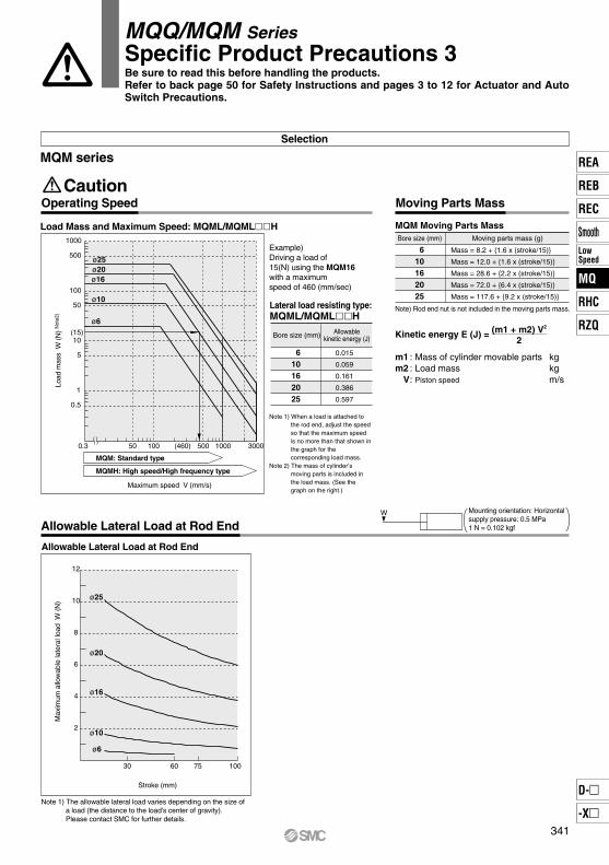
MQM Moving Parts MassBore size (mm) Moving parts mass (g)
610162025
Mass = 8.2 + {1.6 x (stroke/15)}
Mass = 12.0 + {1.6 x (stroke/15)}
Mass = 28.6 + {2.2 x (stroke/15)}
Mass = 72.0 + {6.4 x (stroke/15)}
Mass = 117.6 + {9.2 x (stroke/15)}
Operating Speed
Selection
Caution
MQM series
Load Mass and Maximum Speed: MQML/MQMLH
Moving Parts Mass
Example)Driving a load of15(N) using the MQM16with a maximum speed of 460 (mm/sec)
Note 1) When a load is attached to the rod end, adjust the speed so that the maximum speed is no more than that shown in the graph for the corresponding load mass.
Note 2) The mass of cylinder’s moving parts is included in the load mass. (See the graph on the right.)
Lateral load resisting type: MQML/MQMLH
Bore size (mm) Allowablekinetic energy (J)
610162025
0.015
0.059
0.161
0.386
0.597
Allowable Lateral Load at Rod End
W
Allowable Lateral Load at Rod EndMounting orientation: Horizontalsupply pressure: 0.5 MPa1 N = 0.102 kgf
Note 1) The allowable lateral load varies depending on the size of a load (the distance to the load's center of gravity). Please contact SMC for further details.
ø25
ø20
ø16
ø10
ø6
ø6
ø10
ø16ø20ø25
Maximum speed V (mm/s)
MQM: Standard type
MQMH: High speed/High frequency type
Load
mas
s W
(N
) N
ote2
)
1000 3000
1000
500
100
(15)
(460)
50
10
5
1
0.5
500100500.3
756030
10
8
6
4
2
12
100
Max
imum
allo
wab
le la
tera
l loa
d W
(N
)
Stroke (mm)
MQQ/MQM SeriesSpecific Product Precautions 3
Kinetic energy E (J) =
m1 : Mass of cylinder movable parts kgm2 : Load mass kg V : Piston speed m/s
(m1 + m2) V2
2
Be sure to read this before handling the products.Refer to back page 50 for Safety Instructions and pages 3 to 12 for Actuator and Auto Switch Precautions.
Note) Rod end nut is not included in the moving parts mass.
341
REA
REB
REC
SmoothLowSpeed
MQ
RHC
RZQ
D-
-X
MQ
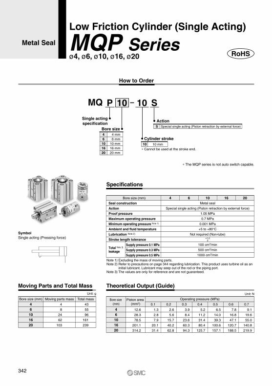
SymbolSingle acting (Pressing force)
Single actingspecification
ActionS
Cylinder stroke10 10 mm
Bore size46101620
4 mm 6 mm10 mm16 mm20 mm
Special single acting (Piston retraction by external force)
Supply pressure 0.1 MPa
Supply pressure 0.3 MPa
Supply pressure 0.5 MPa
Metal seal
Special single acting (Piston retraction by external force)
1.05 MPa
0.7 MPa
0.001 MPa
+5 to +80°CNot required (Non-lube)
100 cm3/min
500 cm3/min
1000 cm3/min
4 6 10 16 20
Specifications
+1.00
Bore size (mm)
Piston area (mm2)
Operating pressure (MPa)
0.70.6
9.1
19.6
55.0
140.8
219.9
Theoretical Output (Guide)
7.8
16.8
47.1
120.7
188.5
0.5
6.5
14.0
39.3
100.6
157.1
0.4
5.2
11.2
31.4
80.4
125.7
0.3
3.9
8.4
23.6
60.3
94.3
0.2
2.6
5.6
15.7
40.2
62.8
0.1
1.3
2.8
7.9
20.1
31.4
12.6
28.3
78.5
201.1
314.2
Bore size (mm)
Moving Parts and Total MassUnit: g
46
101620
46101620
Moving parts mass Total mass
43
55
96
161
239
4
8
24
62
103
Unit: N
∗ The MQP series is not auto switch capable.
Bore size (mm)
Seal construction
Action
Proof pressure
Maximum operating pressure
Minimum operating pressure Note 1)
Ambient and fluid temperature
Lubrication Note 2)
Stroke length tolerance
Note 1) Excluding the mass of moving parts. Note 2) Refer to precautions on page 344 regarding lubrication. This product uses turbine oil as an
initial lubricant. Lubricant may seep out of the rod or the piping port.Note 3) The values are only for reference and are not guaranteed.
MQ P 10 10 S
Metal Seal
Low Friction Cylinder (Single Acting)
MQP Seriesø4, ø6, ø10, ø16, ø20
How to Order
RoHS
Total Note 3)
leakage
∗ Cannot be used at the stroke end.
342
u q w i y e t r
F
A
L B
øI
C
C M
øD
øI
F
A
L B
øD
E
E
M5 x 0.8ø10 depth of counterbore 1.5
2 x OA effective depthRA 2 x øN through
M5 x 0.8
4 x
øN
thro
ugh
2 x 4 x øOBDepth of counterbore RB
2 x 4 x OA effective depth RA
ø10, ø16, ø20
M
M
90°
±0.2
±0.
2
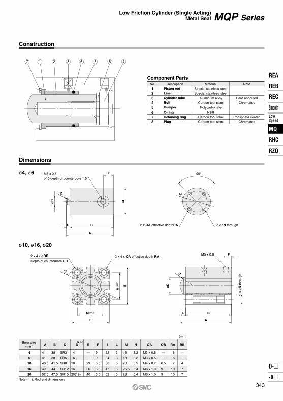
Bore size (mm)
(mm)
4
6
10
16
20
41
41
46.5
49
52.5
A
38
38
41.5
44
47.5
B
—
—
29
36
40
E
9
9
5.5
5.5
5.5
F
22
24
38
47
52
I
3
3
5
5
5
L
16
18
20
25.5
28
M
3.2
3.2
3.5
5.4
5.4
N
—
—
6.5
9
9
6
6
7
10
10
—
—
4
7
7
OB RA RB
M3 x 0.5
M3 x 0.5
M4 x 0.7
M6 x 1.0
M6 x 1.0
OA
SR3
SR5
SR8
SR12
SR15
C
4
6
10
16
20(19)
DNote)
Note) ( ): Rod end dimensions
Construction
Dimensions
No.
12345678
DescriptionPiston rodLinerCylinder tubeBoltBumperO-ringRetaining ringPlug
Special stainless steelSpecial stainless steel
Aluminum alloyCarbon tool steel
PolycarbonateNBR
Carbon tool steelCarbon tool steel
Hard anodizedChromated
Phosphate coatedChromated
Material Note
Component Parts
ø4, ø6
Low Friction Cylinder (Single Acting)Metal Seal MQP Series
343
REA
REB
REC
SmoothLowSpeed
MQ
RHC
RZQ
D-
-X
MQ
MQPcylinder
MQPcylinder
MQP SeriesSpecific Product Precautions
Operation Operation
Disassembly
Lubrication
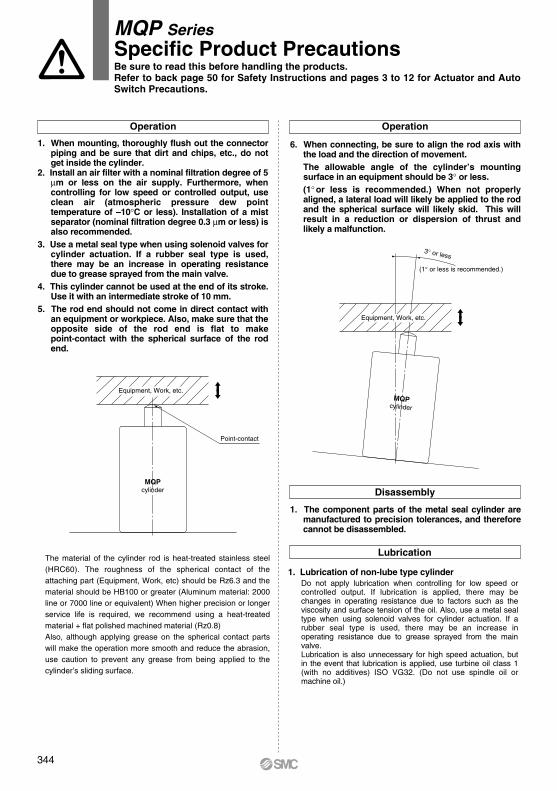
Point-contact
3° or less
(1° or less is recommended.)
The material of the cylinder rod is heat-treated stainless steel (HRC60). The roughness of the spherical contact of the attaching part (Equipment, Work, etc) should be Rz6.3 and the material should be HB100 or greater (Aluminum material: 2000 line or 7000 line or equivalent) When higher precision or longer service life is required, we recommend using a heat-treated material + flat polished machined material (Rz0.8)Also, although applying grease on the spherical contact parts will make the operation more smooth and reduce the abrasion, use caution to prevent any grease from being applied to the cylinder’s sliding surface.
1. The component parts of the metal seal cylinder are manufactured to precision tolerances, and therefore cannot be disassembled.
1. Lubrication of non-lube type cylinderDo not apply lubrication when controlling for low speed or controlled output. If lubrication is applied, there may be changes in operating resistance due to factors such as the viscosity and surface tension of the oil. Also, use a metal seal type when using solenoid valves for cylinder actuation. If a rubber seal type is used, there may be an increase in operating resistance due to grease sprayed from the main valve.Lubrication is also unnecessary for high speed actuation, but in the event that lubrication is applied, use turbine oil class 1 (with no additives) ISO VG32. (Do not use spindle oil or machine oil.)
1. When mounting, thoroughly flush out the connector piping and be sure that dirt and chips, etc., do not get inside the cylinder.
2. Install an air filter with a nominal filtration degree of 5 µm or less on the air supply. Furthermore, when controlling for low speed or controlled output, use clean air (atmospheric pressure dew point temperature of –10°C or less). Installation of a mist separator (nominal filtration degree 0.3 µm or less) is also recommended.
3. Use a metal seal type when using solenoid valves for cylinder actuation. If a rubber seal type is used, there may be an increase in operating resistance due to grease sprayed from the main valve.
4. This cylinder cannot be used at the end of its stroke. Use it with an intermediate stroke of 10 mm.
5. The rod end should not come in direct contact with an equipment or workpiece. Also, make sure that the opposite side of the rod end is flat to make point-contact with the spherical surface of the rod end.
6. When connecting, be sure to align the rod axis with the load and the direction of movement.The allowable angle of the cylinder’s mounting surface in an equipment should be 3° or less.(1° or less is recommended.) When not properly aligned, a lateral load will likely be applied to the rod and the spherical surface will likely skid. This will result in a reduction or dispersion of thrust and likely a malfunction.
Be sure to read this before handling the products.Refer to back page 50 for Safety Instructions and pages 3 to 12 for Actuator and Auto Switch Precautions.
Equipment, Work, etc.
Equipment, Work, etc.
344