Embed Size (px)
Citation preview
66251010-EN - V2.1 - 31/05/161
3600 Series
Art. 3676 - Installation instructions
161
178
218
6246
Fig. 1
6 7 81 2 3 54
ONSW1
1 2 3 4
ONSW2
1 2 3
ONSW3
Fig. 2
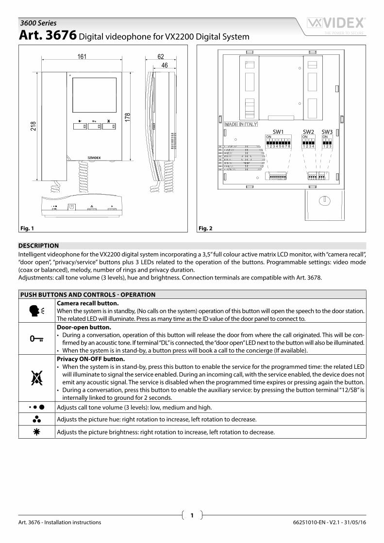
DESCRIPTIONIntelligent videophone for the VX2200 digital system incorporating a 3,5” full colour active matrix LCD monitor, with “camera recall”, “door open”, “privacy/service” buttons plus 3 LEDs related to the operation of the buttons. Programmable settings: video mode (coax or balanced), melody, number of rings and privacy duration.Adjustments: call tone volume (3 levels), hue and brightness. Connection terminals are compatible with Art. 3678.
PUSH BUTTONS AND CONTROLS - OPERATIONCamera recall button.When the system is in standby, (No calls on the system) operation of this button will open the speech to the door station. The related LED will illuminate. Press as many time as the ID value of the door panel to connect to.Door-open button.• During a conversation, operation of this button will release the door from where the call originated. This will be con-
firmed by an acoustic tone. If terminal “DL” is connected, the “door open” LED next to the button will also be illuminated.• When the system is in stand-by, a button press will book a call to the concierge (If available).Privacy ON-OFF button.• When the system is in stand-by, press this button to enable the service for the programmed time: the related LED
will illuminate to signal the service enabled. During an incoming call, with the service enabled, the device does not emit any acoustic signal. The service is disabled when the programmed time expires or pressing again the button.
• During a conversation, press this button to enable the auxiliary service: by pressing the button terminal “12/SB” is internally linked to ground for 2 seconds.
Adjusts call tone volume (3 levels): low, medium and high.
Adjusts the picture hue: right rotation to increase, left rotation to decrease.
Adjusts the picture brightness: right rotation to increase, left rotation to decrease.
Art. 3676 Digital videophone for VX2200 Digital System
66251010-EN - V2.1 - 31/05/162
3600 Series
Art. 3676 - Installation instructions
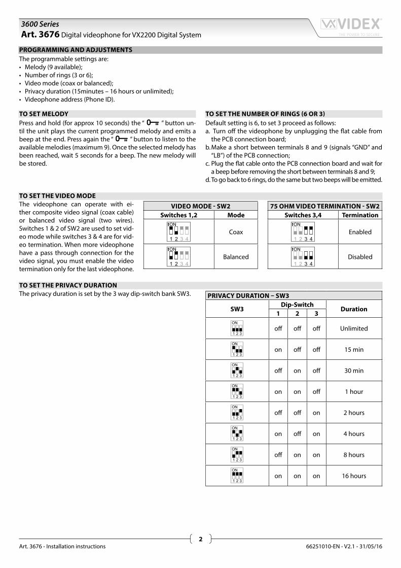
PROGRAMMING AND ADJUSTMENTSThe programmable settings are:• Melody (9 available);• Number of rings (3 or 6);• Video mode (coax or balanced);• Privacy duration (15minutes – 16 hours or unlimited);• Videophone address (Phone ID).
TO SET MELODYPress and hold (for approx 10 seconds) the “ ” button un-til the unit plays the current programmed melody and emits a beep at the end. Press again the “ ” button to listen to the available melodies (maximum 9). Once the selected melody has been reached, wait 5 seconds for a beep. The new melody will be stored.
TO SET THE NUMBER OF RINGS (6 OR 3)Default setting is 6, to set 3 proceed as follows:a. Turn off the videophone by unplugging the flat cable from
the PCB connection board;b. Make a short between terminals 8 and 9 (signals “GND” and
“LB”) of the PCB connection;c. Plug the flat cable onto the PCB connection board and wait for
a beep before removing the short between terminals 8 and 9;d. To go back to 6 rings, do the same but two beeps will be emitted.
TO SET THE VIDEO MODEThe videophone can operate with ei-ther composite video signal (coax cable) or balanced video signal (two wires). Switches 1 & 2 of SW2 are used to set vid-eo mode while switches 3 & 4 are for vid-eo termination. When more videophone have a pass through connection for the video signal, you must enable the video termination only for the last videophone.
VIDEO MODE - SW2Switches 1,2 Mode
Coax
Balanced
75 OHM VIDEO TERMINATION - SW2Switches 3,4 Termination
Enabled
Disabled
TO SET THE PRIVACY DURATIONThe privacy duration is set by the 3 way dip-switch bank SW3. PRIVACY DURATION – SW3
SW3Dip-Switch
Duration1 2 3
off off off Unlimited
on off off 15 min
off on off 30 min
on on off 1 hour
off off on 2 hours
on off on 4 hours
off on on 8 hours
on on on 16 hours
Art. 3676 Digital videophone for VX2200 Digital System
66251010-EN - V2.1 - 31/05/163
3600 Series
Art. 3676 - Installation instructions
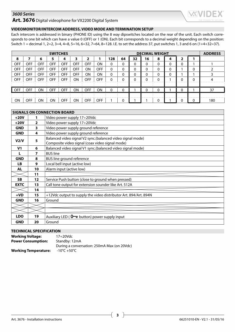
VIDEOMONITOR/INTERCOM ADDRESS, VIDEO MODE AND TERMINATION SETUPEach intercom is addressed in binary (PHONE ID) using the 8 way dipswitches located on the rear of the unit. Each switch corre-sponds to one bit which can have a value 0 (OFF) or 1 (ON). Each bit corresponds to a decimal weight depending on the position: Switch 1 = decimal 1, 2=2, 3=4, 4=8, 5=16, 6=32, 7=64, 8=128. I.E. to set the address 37, put switches 1, 3 and 6 on (1+4+32=37).
SWITCHES DECIMAL WEIGHT ADDRESS8 7 6 5 4 3 2 1 128 64 32 16 8 4 2 1
OFF OFF OFF OFF OFF OFF OFF ON 0 0 0 0 0 0 0 1 1OFF OFF OFF OFF OFF OFF ON OFF 0 0 0 0 0 0 1 0 2OFF OFF OFF OFF OFF OFF ON ON 0 0 0 0 0 0 1 1 3OFF OFF OFF OFF OFF ON OFF OFF 0 0 0 0 0 1 0 0 4
OFF OFF ON OFF OFF ON OFF ON 0 0 1 0 0 1 0 1 37
ON OFF ON ON OFF ON OFF OFF 1 0 1 1 0 1 0 0 180
SIGNALS ON CONNECTION BOARD+20V 1 Video power supply 17÷20Vdc+20V 2 Video power supply 17÷20VdcGND 3 Video power supply ground referenceGND 4 Video power supply ground reference
V2/V 5 Balanced video signal V2 sync.(balanced video signal mode)Composite video signal (coax video signal mode)
V1 6 Balanced video signal V1 sync.(balanced video signal mode)L 7 BUS line
GND 8 BUS line ground referenceLB 9 Local bell input (active low)AL 10 Alarm input (active low)
11SB 12 Service Push button (close to ground when pressed)
EXTC 13 Call tone output for extension sounder like Art. 512A14
+VD 15 +12Vdc output to supply the video distributor Art. 894/Art. 894NGND 16 Ground
LDO 19 Auxiliary LED ( button) power supply inputGND 20 Ground
TECHNICAL SPECIFICATIONWorking Voltage: 17÷20VdcPower Consumption: Standby: 12mA During a conversation: 250mA Max (on 20Vdc)Working Temperature: -10°C +50°C
Art. 3676 Digital videophone for VX2200 Digital System
66251010-EN - V2.1 - 31/05/164
3600 Series
Art. 3676 - Installation instructions
Art. 3676 Digital videophone for VX2200 Digital System
66251010-EN - V2.1 - 31/05/165
3600 Series
Art. 3676 - Installation instructions
Art. 3676 Digital videophone for VX2200 Digital System
66251010-EN - V2.1 - 31/05/166
3600 Series
Art. 3676 - Installation instructions
B
E
C
D
C
A
G
FFig. 2
3600 Series Videophone wall mounting instructions
135c
m
Fig. 1
B
E
C
D
C
A
G
F
Fig. 3
CML
H
I
M
Fig. 4
N
N
Fig. 5
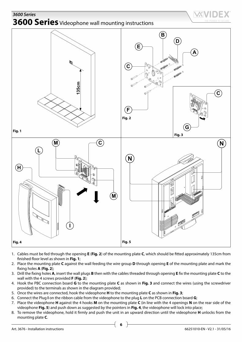
1. Cables must be fed through the opening E (Fig. 2) of the mounting plate C, which should be fitted approximately 135cm from finished floor level as shown in Fig. 1;
2. Place the mounting plate C against the wall feeding the wire group D through opening E of the mounting plate and mark the fixing holes A (Fig. 2);
3. Drill the fixing holes A, insert the wall plugs B then with the cables threaded through opening E fix the mounting plate C to the wall with the 4 screws provided F (Fig. 2);
4. Hook the PBC connection board G to the mounting plate C as shown in Fig. 3 and connect the wires (using the screwdriver provided) to the terminals as shown in the diagram provided;
5. Once the wires are connected, hook the videophone H to the mounting plate C as shown in Fig. 3;6. Connect the Plug I on the ribbon cable from the videophone to the plug L on the PCB connection board G;7. Place the videophone H against the 4 hooks M on the mounting plate C (in line with the 4 openings N on the rear side of the
videophone Fig. 5) and push down as suggested by the pointers in Fig. 4, the videophone will lock into place;8. To remove the videophone, hold it firmly and push the unit in an upward direction until the videophone H unlocks from the
mounting plate C.
66251010-EN - V2.1 - 31/05/167
3600 Series
Art. 3676 - Installation instructions
Note
MANUFACTURERVIDEX ELECTRONICS S.P.A.Via del Lavoro, 1 - 63846 Monte Giberto (FM) ItalyTel (+39) 0734 631669 - Fax (+39) 0734 632475www.videx.it - [email protected]
CUSTOMER SUPPORTAll Countries:VIDEX ELECTRONICS S.P.A.www.videx.it - [email protected]: +39 0734-631669 - Fax: +39 0734-632475
UK Customers:VIDEX SECURITY LTDwww.videx-security.comTech Line: 0191 224 3174 - Fax: 0191 224 1559
The product is CE marked demonstrating its conformity and is for distribution within all member states of the EU with no restrictions. This product follows the provisions of the European Directives 2014/30/EU (EMC); 2014/35/EU (LVD); 2011/65/EU (RoHS): CE marking 93/68/EEC.
Main UK office:VIDEX SECURITY LTD1 Osprey Trinity ParkTrinity WayLONDON E4 8TDPhone: (+44) 0870 300 1240Fax: (+44) 020 8523 [email protected]
Northern UK office:VIDEX SECURITY LTDUnit 4-7Chillingham Industrial EstateChapman StreetNEWCASTLE UPON TYNE - NE6 2XXTech Line: (+44) 0191 224 3174Phone: (+44) 0870 300 1240Fax: (+44) 0191 224 1559
Greece office:VIDEX HELLAS Electronics48 Filolaou Str.11633 ATHENSPhone: (+30) 210 7521028 (+30) 210 7521998 Fax: (+30) 210 [email protected]
Danish office:VIDEX DANMARKHammershusgade 15DK-2100 COPENHAGENPhone: (+45) 39 29 80 00Fax: (+45) 39 27 77 [email protected]
Benelux office:VIDEX BENELUXE3 Iaan, 93B-9800 DEINZEPhone: (+32) 9 380 40 20Fax: (+32) 9 380 40 [email protected]