Embed Size (px)
Citation preview

38RRJET | Volume 7 | Issue 1 | January, 2018
Research & Reviews: Journal of Engineering and Technology e-ISSN:2319-9873
36 Sectors DTC Based on Fuzzy Logic of Sensorless Induction Motor DrivesHabib Benbouhenni*
National Polytechnic School of Oran Maurice Audin, Oran, Algeria
Research Article
INTRODUCTIONThe induction motors have been widely used in many industrial and daily life applications such as pumps, fans and compressor
due to its low cost, low maintenance, high robustness, simple construction and high efficiency. Nowadays, the induction motor drives have been able to be used in variable speed applications with the rapid development of power electronics [1].
A control literature review shows that a variety of solutions has been proposed for the control of induction motor systems. In the linear case, one has to mention the scalar control which is the first scheme proposed for this task. It is easy to implement but it does not provide good performance. The second well-known scheme is the vector control technique called also field oriented control (FOC) proposed by Blaschke. The main disadvantage of this later control technique is the inherent coupling of the speed sensor on the motor rotor shaft reduces its robustness [2]. The direct torque control (DTC) method has emerged as an alternative to Field Oriented Control (FOC) method for high performance AC drives since it was firstly proposed in the mid-1980 [3]. The main advantages of direct torque control are absence of coordinate transformation and current regulator. In this method, stator voltage vectors are selected according to the differences between the reference and actual torque and stator flux linkage [4]. The basic idea of this method is to use non-linear estimators of the torque and flux, making it possible to eliminate the controllers of the stator currents [5]. However, the main limit of conventional DTC scheme is high torque ripple, variable switching frequency, and the mean torque output, which does not match the torque demond. A variety of techniques have been proposed to overcome some of the drawbacks present in DTC. Some solution proposed are: DTC with space vector modulation (SVPWM), the use of a duty-ration controller to introduce a modulation between active vectors chosen from the look-up table and the zero vectors, use of artificial intelligence techniques. However the complexity of the control is considerably increased [6]. In the other hand, the utilization of multilevel inverter topology in the DTC system has gained popularity for the medium and high voltage applications. Typically, there are three types of multilevel inverters topologies. Those types are the neutral point clamped (NPC), flying capacitor (FC) and cascade H-bridge multilevel inverters (CHMI) [7]. In the other hand, multilevel inverters have the advantages of overcoming voltage limit capability of semiconductor switches, and improving, 2 harmonic profiles of output waveforms. The output voltage waveform approaches a sine wave, thus having practically no common-mode voltage and no voltage surge to the motor windings. Furthermore, the reduction in dv/dt can prevent motor windings and bearings from failure [8]. In this paper, a 5-level neutral point clamped multilevel inverter is used with look up table based DTC drive.
Common disadvantages of conventional DTC are high torque ripple, it also needs flux and torque estimators and therefore,
Received date: 25/11/2017
Accepted date: 28/01/2018
Published date: 28/02/2018
*For Correspondence
Habib Benbouhenni, National Polytechnic School of Oran Maurice Audin, Oran, Algeria.
E-mail: [email protected]
Keywords: Direct torque control, Induction motor, Fuzzy logic, Hysteresis comparators, PI, Total harmonic distortion
ABSTRACT
This paper presents an improved five-level direct torque control (DTC) with 36 sectors of induction motor (IM) based on fuzzy logic. This intelligent technique was used to replace, on the one hand the hysteresis comparators in order to reduce THD (Total Harmonic Distortion) of stator current, torque ripple and stator flux ripple, on other hand and the classic integral proportional (PI) in order to increase the response time period of the system, to optimize the performances of the closed loop control, and to adjust the parameters of the regulator to changes in the reference level. The validity of the proposed methods is confirmed by the simulation results

39RRJET | Volume 7 | Issue 1 | January, 2018
Research & Reviews: Journal of Engineering and Technology e-ISSN:2319-9873
accurate machine parameters are required. For that reason the application of artificial neural network and fuzzy logic control attracts the attention of many scientists from all over the world [9]. This paper is devoted to fuzzy logic direct torque control of sensorless IM fed by five-level diode clamped inverter.
In this paper two different DTC scheme will be compared with each other. These two schemes are conventional DTC with five-level NPC inverter, and five-level DTC with fuzzy logic controllers (fuzzy speed controller and fuzzy hysteresis comparators). The proposed scheme is described clearly and simulation results are reported to demonstrate its effectiveness. The proposed control scheme is implemented with Matlab.
FIVE-LEVEL NEUTRAL POINT CLAMPED INVERTERThe very first topology has switches at its neutral point to control the voltage levels. In 1980, Nabae and his friends
modified this topology such that the neutral point voltage application to the output and neutral point voltage balance have been accomplished by diode pairs [10]. Figure 1 shows the circuit of a five-level diode clamped inverter and the switching states of each leg of the inverter. Each leg is composed of two upper and lower switches with anti-parallel diodes. It is composed by 24 pair’s transistor-diode. Every leg of this inverter includes eight pairs. Four series DC-link capacitors split the DC-bus voltage in half, and 18 clamping diodes confine the voltage across the switches within the voltage of the capacitors, each leg of the inverter can have five possible switching states; 4, 3, 2, 1, or 0.
Figure 1. Schematic diagram of a five-level inverter.
A five-level inverter can achieve 60 separate positions in the phase corresponding to the 61 sequences of the voltage inverter. The representation of the space voltage vectors of a five-level NPC inverter for all switching states is given by Figure 2.
Figure 2. Space vector diagram of five-level inverter.
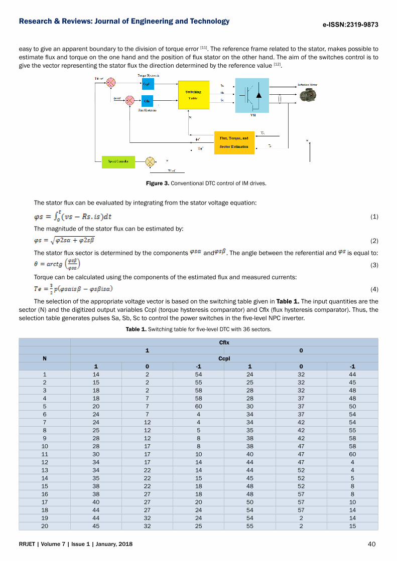
CONVENTIONAL DTC CONTROL WITH FIVE-LEVEL INVERTERConfiguration of the basic DTC with five-level inverter is illustrated in Figure 3. In these control uses two hysteresis controllers
for stator flux and developed torque, respectively. As the DTC control strategy is not based on mathematical analysis, it is not
40RRJET | Volume 7 | Issue 1 | January, 2018
Research & Reviews: Journal of Engineering and Technology e-ISSN:2319-9873
easy to give an apparent boundary to the division of torque error [11]. The reference frame related to the stator, makes possible to estimate flux and torque on the one hand and the position of flux stator on the other hand. The aim of the switches control is to give the vector representing the stator flux the direction determined by the reference value [12].
Figure 3. Conventional DTC control of IM drives.
The stator flux can be evaluated by integrating from the stator voltage equation:
(1)
The magnitude of the stator flux can be estimated by:
(2)
The stator flux sector is determined by the components and . The angle between the referential and is equal to:
(3)
Torque can be calculated using the components of the estimated flux and measured currents:
(4)
The selection of the appropriate voltage vector is based on the switching table given in Table 1. The input quantities are the sector (N) and the digitized output variables Ccpl (torque hysteresis comparator) and Cflx (flux hysteresis comparator). Thus, the selection table generates pulses Sa, Sb, Sc to control the power switches in the five-level NPC inverter.
Table 1. Switching table for five-level DTC with 36 sectors.
Cflx 1 0N Ccpl 1 0 -1 1 0 -11 14 2 54 24 32 442 15 2 55 25 32 453 18 2 58 28 32 484 18 7 58 28 37 485 20 7 60 30 37 506 24 7 4 34 37 547 24 12 4 34 42 548 25 12 5 35 42 559 28 12 8 38 42 58
10 28 17 8 38 47 5811 30 17 10 40 47 6012 34 17 14 44 47 413 34 22 14 44 52 414 35 22 15 45 52 515 38 22 18 48 52 816 38 27 18 48 57 817 40 27 20 50 57 1018 44 27 24 54 57 1419 44 32 24 54 2 1420 45 32 25 55 2 15

41RRJET | Volume 7 | Issue 1 | January, 2018
Research & Reviews: Journal of Engineering and Technology e-ISSN:2319-9873
21 48 32 28 58 2 1822 48 37 28 58 7 1823 50 37 30 60 7 2024 54 37 34 4 7 2425 54 42 34 4 12 2426 55 42 35 5 12 2527 58 42 38 8 12 2828 58 47 38 8 17 2829 60 47 40 10 17 3030 4 47 44 14 17 3431 4 52 44 14 22 3432 5 52 45 15 22 3533 8 52 48 18 22 3834 8 57 48 18 27 3835 10 57 50 20 27 4036 14 57 54 24 27 44
Two-level stator flux and three-level torque hysteresis controllers are used according to the outputs of the torque and flux controllers Figure 4.
a) Stator flux hysteresis comparator
b) Three-level torque hysteresis comparator
Figure 4. Hysteresis comparators.
FIVE-LEVEL DTC WITH FUZZY CONTROLLERS
The principle of five-level DTC with fuzzy controllers is similar to conventional DTC with five-level NPC inverter. The difference is using a fuzzy controller to replace the hysteresis comparators, and PI speed controller. As shown in Figure 5. The main objective of this study is the reduction of the THD value of stator current, electromagnetic torque ripples and stator flux ripples.
Figure 5. DTC control with fuzzy controllers.
DESIGN OF FUZZY SPEED CONTROLLER

42RRJET | Volume 7 | Issue 1 | January, 2018
Research & Reviews: Journal of Engineering and Technology e-ISSN:2319-9873
In the objective to control the static error and to reduce the time response while preserving the system stability, the proportional integral corrector PI used is replaced with a fuzzy logic controller [13]. The fuzzy control is basically nonlinear and adaptive in nature, giving robust performance under parameter variation and load disturbance effet [14]. Fuzzy logic speed controller design is designed based on the human expert knowledge rule base. It does not require any mathematical model of the plant [15]. The fuzzy controller design is based on intuition and simulation. These values compose a training set which is used to obtain the table rules [11]. The block diagram of the fuzzy logic speed controller is shown in Figure 6. On possible initial rule base, that can be used in drive systems for a fuzzy logic controller, consist of 49 linguistic rules, as shown in Table 2 [16,17], and gives the change of the output of fuzzy logic controller in term of two input: the error (e=wref – w) and change of error (Δe).
Table 2. Fuzzy rules of speed.
e NL NM NP EZ PS PM PLΔe NL NL NL NL NL NM NP EZNM NL NL NL NM NP EZ PSNP NL NL NM NP EZ PS PMEZ NL NM NP EZ PS PM PLPS NM NP EZ PSPM PM PL PLPM NP EZ PS PM PL PL PLPL EZ PS PM PL PL PL PL
Figure 6. Fuzzy logic speed controller.
Figures 7 and 8 show the membership functions of error and the change variables respectively.
Figure 7. Membership functions for error in speed.

43RRJET | Volume 7 | Issue 1 | January, 2018
Research & Reviews: Journal of Engineering and Technology e-ISSN:2319-9873
Figure 8. Membership functions for change in error.
DESIGN OF FUZZY HYSTERESIS COMPARATORSThe Principe of the proposed fuzzy hysteresis comparators is to replace the two hysteresis comparators of torque and flux
by the fuzzy logic. The block diagram for fuzzy based torque and stator flux hysteresis comparators is shown in Figures 9 and 10. The fuzzy controller design is based on intuition and simulation [18]. The fuzzy rules for the proposed hysteresis comparators are given in Table 2.
Figure 9. Fuzzy logic control of speed regulation.
Figure 10. Fuzzy logic control of speed regulation.
RESULTS AND DISCUSSION
The induction motor used for the simulations has the following parameters: A 3-phase, 3 poles, Pn=1 MW; fs=60 Hz; Rs=0.228Ω; Rr=0.332Ω; Ls=0.0084H; Lr=0.0082H; Lm=0.0078H; J=20 kg.m2. To compare with conventional five-level DTC and five-level DTC with fuzzy controllers for IM drive are simulated. All Figs are the responses to step change load torque command from 0 to 6500 N.m. The results of simulation of conventional five-level DTC and five-level DTC with fuzzy logic controllers are shown in Figures 11 and 12 respectively.
Figure 11. Performances of five-level DTC for IM.

44RRJET | Volume 7 | Issue 1 | January, 2018
Research & Reviews: Journal of Engineering and Technology e-ISSN:2319-9873
Figure 12. Performances of five-level DTC with fuzzy controllers for IM.
From the simulation results presented in Figures 11 and 12 it is apparent that the THD value of stator current for the five-level DTC with intelligent controllers (fuzzy speed controller and fuzzy hysteresis comparators) is considerably reduced. Table 3 shows the comparative analysis of THD value for stator current.
Table 3. Comparative analysis of THD value.
Conventional DTC with five-level inverter Five-level DTC with fuzzy controllers 4.67% 3.98%
In the other hand, the dynamics of the components of the stator flux are not affected by the application of these load guidelines. Torque response comparing curves are shown in Figure 13. The torque ripple is significantly reduced when the fuzzy controllers is in use (Figure 13).
a) Conventional five-level DT
b) DTC control with fuzzy controllers
Figure 13. Zoom in the torque.
Figure 14 shows the flux responses of both the five-level DTC control and the five-level DTC with fuzzy controllers. It is found

45RRJET | Volume 7 | Issue 1 | January, 2018
Research & Reviews: Journal of Engineering and Technology e-ISSN:2319-9873
that the proposed variable band torque hysteresis and PI controller based DTC scheme exhibits smooth response and lesser ripple in flux as compared to the conventional five-level DTC scheme.
a) Conventional five-level DTC. b) DTC control with fuzzy controllers.
Figure 14. Zoom in the flux.
CONCLUSIONThis paper presents a five-level DTC with 36 sectors for the IM with fuzzy controllers. This controllers determinates the de-
sired amplitude of hysteresis comparators band and classical PI controller of speed. The proposed scheme was simulated and compared with conventional five-level DTC with 36 sectors using Matlab/Simulink. The five-level DTC with fuzzy controllers de-creases considerably the torque ripples, stator flux ripples and THD value of stator current.
REFERENCES1. Erdal K, et al. Adaptive PI controller based on RBF neural network for speed control of induction motor. International
Conference on Natural Science and Engineering. 2016.
2. Farid B, et al. Flatness based nonlinear sensorless control of induction motor systems. International Journal of Power Electronics and Drive System. 2016;7:265-278.
3. Manoj KS, et al. Direct torque control for three-level Neutral Point clamped inverter-fed induction motor drive. Engineering, Technology and Applied Science Research. 2012;2;201-208.
4. Sreenivasa M, et al. Comparative analysis of fuzzy DTC and ANNDTC for induction motor. International Journal of Emerging Trends in Engineering and Development. 2013;2:483-493.
5. Krzysztof O, Direct torque control of an induction motor using the fuzzy controller. Przegląd Elektrotechniczny. 2015;46;179-181.
6. Ehsa HK, et al. DTC-SVM scheme for induction motor fed with a three-level inverter. International Journal of Mechanical, Aerospace, Industrial, Mechatronic and Manufacturing Engineering. 2008;2:958-962.
7. Sundram Al R, et al. Improvise 3-level DTC of induction machine using constant switching frequency method by utilizing multiband carrier. International Journal of Power Electronics and Drive System. 2016;7:638-647.
8. Elakhdar B, et al. Three-level DTC based on Fuzzy logic and neural network of sensorless DSSM using extende kalman filter. International Journal of Power Electronics and Drive System. 2015;5:453-463.
9. Ahmed HA, et al. Improvement of direct torque control of induction motor drives using neuro-fuzzy controller. Journal of Multidisciplinary Engineering Science and Technology. 2015;2:2913-2918.
10. Hulya O, et al. Performance comparison of 2-level and 3-level converters in a wind energy conversion system. Rev Roum Sci Techn-Electrotechn et Energ. 2016;61:388-393.
11. Lamia Y, et al. Direct torque control of induction motors with fuzzy minimization torque ripple. Engineering and Computer Science. 2009;2.
12. Bachir M, et al. Experimental DTC of an induction motor applied to optimize a tracking system. International Conference on Renewable Energies and Power Quality (ICREPQ’12), Santiago de Compostela. 2012;1:1524-1529.
13. Abdesselem C, Direct torque control of induction motor based on space vector modulation using a fuzzy logic speed controller. Jordan Journal of Mechanical and Industrial Engineering. 2014;8:169-176.
14. Ahmed T, et al. Fuzzy controller of switched reluctance motor. Acta Electrotehnica. 2006;47:124-131.
15. Sudheer H, et al. Improved fuzzy logic based DTC of induction machine for wide range of speed control using AI based controllers. Journal of Electrical Systems. 2016;12:301-314.
16. Moualdia A. DTC-SVM and DPC control strategies applied to an MADA used for wind power generation. PhD Thesis, Ecole

46RRJET | Volume 7 | Issue 1 | January, 2018
Research & Reviews: Journal of Engineering and Technology e-ISSN:2319-9873
Nationale Polytechnique. 2014.
17. Habib B. New approach to DTC control modified by artificial intelligence techniques of an asynchronous machine. Journal of Advanced Research in Science and Technology. 2017;4:509-528.
18. Idir A, et al. Direct torque control of three phase induction motor drive using fuzzy logic controllers for low torque ripple. Engineering and Technology. 2013;2:78-83