Embed Size (px)
Citation preview

International Journal of Computer Engineering and Applications, Volume VII, Issue III, Part I,
September 14
98 O. Hemakesavulu , C. Ganesh and M. Manasa
SIMULATION OF FUZZY LOGIC CONTROLLER BASED
MATRIX CONVERTER DTC-SVM METHOD FOR INDUCTION
MOTOR DRIVE
O. Hemakesavulu 1, C. Ganesh
2 , M. Manasa
3
1,2 Associate Professor, Department of EEE, Annamacharya institute of technology and sciences,
Rajampet, AP, India 3 PG Student, Department of EEE, Annamacharya Institute of Technology & Sciences, Rajampet,
AP, India
ABSTRACT: A Fuzzy space vector modulation direct torque control strategy for induction machine based on Matrix converter is proposed to improve the low speed performance of the direct torque control (DTC) system. The generation of torque reference voltage vector were designed in the Fuzzy logic controller. This novel method provides a precious input power factor control capability. The conventional principles of DTC and Space vector modulation of matrix converter were described. The Performance of the proposed drive system is evaluated through simulation using MATLAB-SIMULINK package to identify the effectiveness of new method. The Simulation results of Induction motor control at both steady state and transient state are shown to improve the low- speed performance and strong adaptability of novel control strategy.
Keywords: Matrix converter, Induction motor, Direct torque control method, SVM, Fuzzy Logic Controller, Low Speed performance
[1] INTRODUCTION
The Direct Torque Control (DTC) method has been proposed in the mid 1980’s, The
Direct Torque Control (DTC) method for AC machines is prevalently utilized in many
variable speed drives, especially in case the torque control is more desired than speed
control. Direct torque control (DTC) is a high-dynamic and high performance control technique
for induction motor drives which has been developed in the last two decades as possible
alternative to DC servo drives [1], [2]. In direct torque controlled adjustable speed drives, the
motor flux and the electromagnetic torque are the reference quantities which are directly
controlled by the applied inverter voltage vector. The main advantages of DTC are: fast torque
and flux responses, no need for speed or position sensors and no requirements for coordinate
transformation. DTC has also some disadvantages: the difficulty to control the torque and the
flux at very low speed, the higher current and torque ripple which imply higher machine losses
and noise, the inherent variable switching frequency and the lack of direct current control.
Simulation Of Fuzzy Logic Controller Based Matrix Converter DTC-SVM Method For Induction
Motor Drive
99 O. Hemakesavulu , C. Ganesh and M. Manasa
In the past two decades, due to the need to increase the quality and the efficiency of
power supply and usage the three phase matrix converter has become a major modern energy
converter and has emerged from the previously conventional energy conversion modules as one
of the best substitutions. Matrix converter fed motor drive is superior to pulse width modulation
(PWM) inverter drives because it provides bidirectional power flow, sinusoidal input/output
currents, and adjustable input power factor [3], [4] . Furthermore, matrix converter allows a
compact design due to the lack of dc-link capacitors for energy storage. However, only a few
of practical matrix converters have been applied to vector control system of induction motors
(IM) for the reason: Modulation technique and commutation control are more complicated
than conventional PWM inverter [5].
The switching frequency of voltage source inverter is Non-Fixing. Non-Fixing
switching frequency capability of the inverter not to be used fully [6], [7]. Secondly, there is
sharp increase or decrease of torque because only one voltage vector works in a sampling
period and the options of vector is limited. Fuzzy logic control has manifested its
robustness, and has been extensively researched and used as one of the intelligent control
methods in control field [8], [9] ,[10] . The new SVM-DTC strategy uses fuzzy logic controller
substitute the original PI controller. In this paper, a new Fuzzy DTC control for matrix
converter is proposed which allows under the constraint of unity input power factor, the
generation of the voltage vectors required to implement the DTC of three phase induction
motor. Depending on the induction motor operating point such vectors might be applied and
consequently the electromagnetic torque ripple is reduced.
[2] DIRECT TORQUE CONTROL STRUCTURES
[2.1] MATHEMATICAL MODE OF INDUCTION MACHINE
The basic model of DTC induction motor scheme is shown in Fig. 1. At each sample
time, the two stator currents and isa and isb the DC bus voltage Vdc are sampled.
Using the inverter voltage vector, the α,β components of the stator voltage space vector
in the stationary reference frame are calculated as follows.
Vsαref = Vdc (
)
Vsβref=
√ Vdc ( ) (1)
The α,β components of the stator current space vector are calculated using
Isα = isa
Isβ =
√ (2)
The stator flux is a function of the rotor flux which is provides from the flux
observer
Ψsα = σ Ls Isα +
Ψrα
Ψsβ = σ Ls Isβ +
Ψrβ (3)

International Journal of Computer Engineering and Applications, Volume VII, Issue III, Part I,
September 14
100 O. Hemakesavulu , C. Ganesh and M. Manasa
Then the magnitude of Stator flux is calculated by
|Ψs| = √Ψ α Ψ β (4)
The electromagnetic torque is calculated by
Te =
p(Ψ α β Ψ β α ) (5)
Where p is the number of poles
The torque and the flux errors are defined is
ΔΨs = |Ψsref| - |Ψs|
ΔTe = Tref – Te (6)
[2.2] PRINCIPLE OF DIRECT TORQUE CONTROL
The basic principle in conventional DTC for induction motors is to directly select stator
voltage vectors by means of a hysteresis stator flux and torque control. As it is shown in Fig 1.
The inverter switching states are determined by the torque and flux errors according
to the sector determined. In order to maintain the estimated and torque within their
boundaries which a by the two hysteresis bandwidths as shown in figure 2b, at each sampling
period, the torque and are estimated and compared with the corresponding reference values
before passing the hysteresis comparator.
Figure : 1. Block Diagram of DTC
In particular, stator flux is controlled by a two-level hysteresis comparator, whereas the
torque is controlled by a three-level comparator. The position of the stator flux is detected,
and the most suitable space vector among 8 space vectors generated by a VSI is selected from
the switching table given in Table 1.

Simulation Of Fuzzy Logic Controller Based Matrix Converter DTC-SVM Method For Induction
Motor Drive
101 O. Hemakesavulu , C. Ganesh and M. Manasa
Table :1. DTC Switching table
[3] DTC MATRIX CONVERTER STRUCTURES (DTC-MC)
[3.1] WORKING PRINCIPLE OF MATRIX CONVERTER
A MC is an AC-AC converter, with m x n bidirectional switches, which connects an m-
phase voltage source to an n-phase load. The three-phase, 3x3 switches, MC shown in Fig.2 is
the most interesting. It connects a three phase voltage source to a three-phase load. The matrix
converter has a simple topology and a compact design due to the lack of DC-link capacitor for
energy storage.. In the MC vsi, i={A,B,C} are the source voltages, isi, i={A,B,C} are the
source currents, vjN, j={a,b,c} are the load voltages, ij, j={a,b,c} are the load currents, vi,
i={A,B,C} are the MC input voltages ii ,i={A,B,C}are the input currents. A switch, Sij,
i={A,B,C}, j={a,b,c} can connect phase i of the input to phase j of the load.
The mathematical model of Matrix converter can be derived from fig 2 as follows:
[
( ) ( ) ( )
] = [
( ) ( ) ( ) ( ) ( ) ( ) ( ) ( ) ( )
] . [
( ) ( ) ( )
] (7)
[
( ) ( ) ( )
] = [
( ) ( ) ( ) ( ) ( ) ( ) ( ) ( ) ( )
] . [
( ) ( ) ( )
] (8)
Sector
6
Sector
5
Sector
4
Sector
3
Sector 2
Sector 1
(
)
(
)
(
,
)
(
)
(
,
)
(
,
)
Decrease
Flux
Increase
Torque
100
110
010
011
001
101
Decrease
Torque
011
001
101
100
110
010
Increase
Flux
Increase
Torque
110
010
011
001
101
100
Decrease
Torque
001
101
100
110
010
011

International Journal of Computer Engineering and Applications, Volume VII, Issue III, Part I,
September 14
102 O. Hemakesavulu , C. Ganesh and M. Manasa
Figure: 2. Block diagram of Matrix converter
[3.2] MATRIX CONVERTER THEORY
The three-phase matrix converter module includes nine bi-directional switches as
shown in Figure 3. There are 27 switching configuration states, which mean 27 possible space
vectors can be used to control IM and can be split respectively into 3 groups as shown in
Table 1; in Group I, two output lines are connected to one of the other input lines; in Group II,
all output lines are connected to a common input line; while in Group III, each output line is
connected to a different input line. The corresponding output line-to-neutral voltage vector
and input line current vector have fixed directions as represented in Figure 2. However, Group
III is not useful. Only 18 non-zero space vectors in Group I (±1, ±2, …, ±9) and 3 zero space
vectors in Group II (0a, 0b, 0c) can be usually employed in the modern control techniques for
the matrix converter (such as the Space Vector Modulation, DTC methods, etc.)
(b)
(a)
Figure : 3. (a) output line to neutral voltage vectors
(b) output currents

Simulation Of Fuzzy Logic Controller Based Matrix Converter DTC-SVM Method For Induction
Motor Drive
103 O. Hemakesavulu , C. Ganesh and M. Manasa
[3.3] DTC PRINCIPLES BY MATRIX CONVERTER
The basic DTC principles using matrix converters can be briefly described as follows:
at each sampling period, the proper switching configuration, which allows the compensation
of instantaneous errors in the stator flux magnitude and torque, is selected under the
constraint of unity input power factor. This last requirement of the input side of the matrix
converter is intrinsically satisfied if the average value of sin (ψi) is maintained close to zero,
where ψi is the displacement angle between the input line voltage and input line current. The
hysteresis comparator directly controls this variable and the average value of sin (ψi) is
obtained by applying a low-pass filter to its instantaneous value. The average value of sin (ψi)
is controlled close to zero because the input power factor is aimed close to unity. As a
facultative example, after calculation at the first time of each sampling period and considering
the stator flux vector lying in sector 1, the input voltage vector lying in sector 2, the output of
the torque hysteresis comparator, the flux hysteresis comparator and the hysteresis comparator
of the average value of sin (ψi) are respectively cT = +1, cϕ = 0 and cψ=+1. As shown in
Figure 4, first with cT =+1, cϕ = 0 and the stator flux in sector 1, the suitable voltage vector
V6-vsi is the VSI output voltage vector by the DTC algorithm in a given switching period
from Table 2.
Group
Vector
A B C
Vs αo
ii βi
I
+1MC a b b 2/3Vab 0
2/√ isa
-1MC b a a -2/3vab 0
-2/√ isa
+2MC b c c 2/3vbc 0
2/√ isa
-2MC c b b -2/3vbc 0 - 2/√ isa
+3MC c a a 2/3vca 0
2/√ isa
-3MC a c c -2/3vca 0 -2/√ isa
+4MC b a b 2/3Vab
2/√ isb
-4MC a b a -2/3vab
- 2/√ isb
+5MC c b c 2/3vbc
2/√ isb
-5MC b c b -2/3vbc
-2/√ isb
+6MC a c a 2/3vca
2/√ isb
-6MC c a c -2/3vca
- 2/√ isb
+7MC b b a 2/3Vab
2/√ isc
-7MC a a b -2/3vab
- 2/√ isc

International Journal of Computer Engineering and Applications, Volume VII, Issue III, Part I,
September 14
104 O. Hemakesavulu , C. Ganesh and M. Manasa
Table : 2. Possible switching configurations of MC
Then, with the chosen VSI voltage vector V6-vsi, cψ= +1 and the input voltage vector
in sector 2, the opportune matrix converter voltage vector is finally selected as V-5MC from
Table 3.The schematic of the DTC method using the matrix converter fed induction motor is
represented in Figure 4. The reference values of the torque and the stator flux are compared
with the estimated values and coordinate with the average value of the sin (ψi) hysteresis
comparator. In the lower part of the block diagram, the estimators of the electromagnetic
torque, stator flux and the average value of sin (ψi) are represented. These estimators require
the knowledge of input and output of voltages and currents for the matrix converter.
Table :3. DTC switching table using MC
Sector
of v
1
2
3
4
5
6
cψ
+1
-1
+1
-1
+1
-1
+1
-1
+1
-1
+1
-1
V1-Vsi
-3MC
+1MC
+2MC
-3MC
-1MC
+2MC
+3MC
-1MC
-2MC
+3MC
+1MC
-2MC
V2-Vsi
+9MC
-7MC
-8MC
+9MC
+7MC
-8MC
-9MC
+7MC
+8MC
-9MC
-7MC
+8MC
V3-Vsi
-6MC
+4MC
+5MC
-6MC
-4MC
+5MC
+6MC
-4MC
-5MC
+6MC
+4MC
-5MC
V4-Vsi
+3MC
-1MC
-2MC
+3MC
+1MC
-2MC
-3MC
+1MC
+2MC
-3MC
-1MC
+2MC
V5-Vsi
-9MC
+7MC
+8MC
-9MC
-7MC
+8MC
+9MC
-7MC
-8MC
+9MC
+7MC
-8MC
V6-Vsi
+6MC
-4MC
-5MC
+6MC
+4MC
-5MC
-6MC
+4MC
+5MC
-6MC
-4MC
+5MC
+8MC c c b 2/3vbc
2/√ isc
-8MC b b c -2/3vbc
- 2/√ isc
+9MC a a c 2/3vca
2/√ isc
-9MC c c a -2/3vca
- 2/√ isc
II
0a a a a 0 - 0 -
0b b b b 0 - 0 -
0c c c c 0 - 0 -
III
x a b c x x x x
x a c b x x x x
x b c a x x x x
x b a c x x x x
x c a b x x x x
x c b a x x x x
Simulation Of Fuzzy Logic Controller Based Matrix Converter DTC-SVM Method For Induction
Motor Drive
105 O. Hemakesavulu , C. Ganesh and M. Manasa
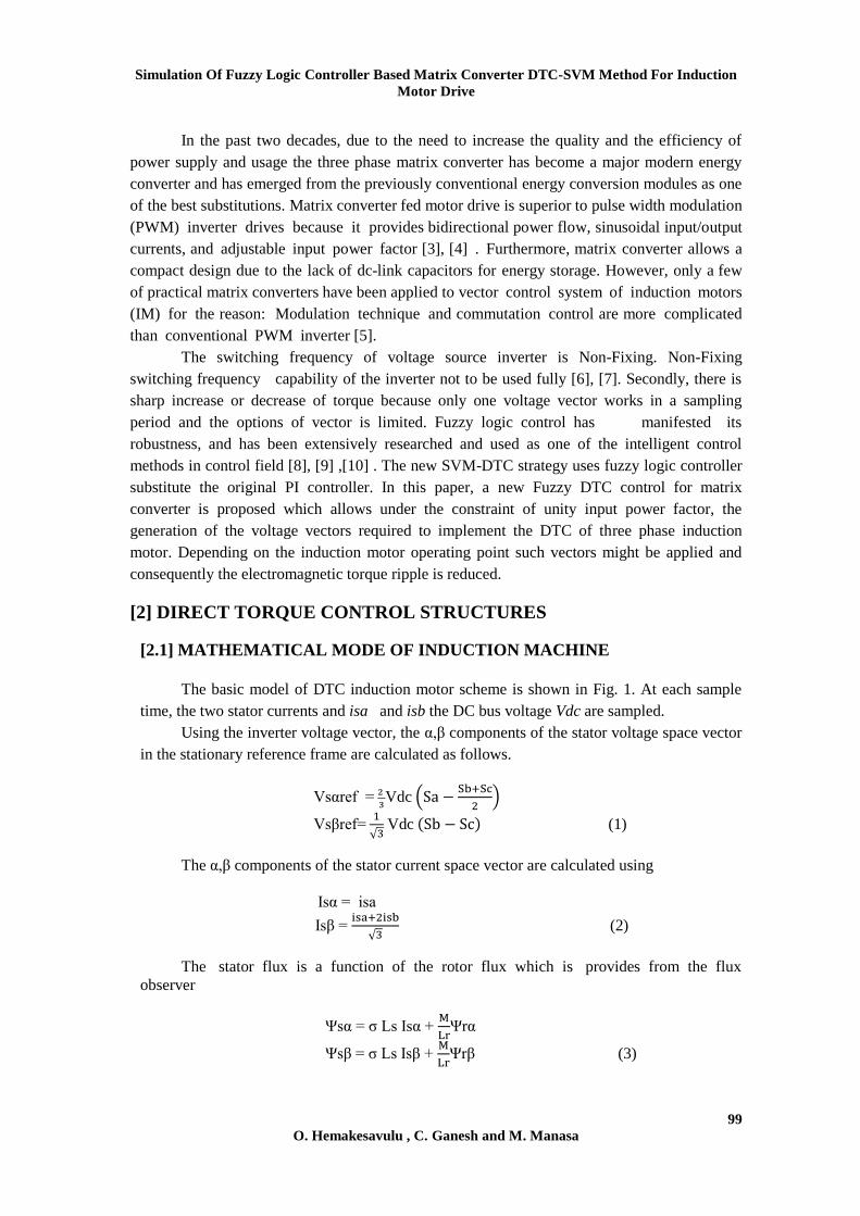
However, only the input voltages and the output currents of the matrix converter
module are by sensors, while other quantities such as the input voltages of the induction motor
and the input currents of the matrix converter module are calculated from the previous
switching states, the input voltages and the output currents of the matrix converter module
structure. Fig 4 represents the block diagram of DTC-MC with PI controller. The direct torque
control with space vector modulation technique (DTC-SVM) was proposed in order to
improve the classical DTC. In control structures space vector modulation technique is used.
Basically, the controller calculates the required stator voltage vector and then it is realized by
space vector modulation technique. The output of PI controller can be represented as the
stator voltage components in the stator flux oriented coordinates.
Figure :4. Block diagram of DTC-MC with PI Controlle
[4] DESIGN OF FUZZY LOGIC CONTROLLER
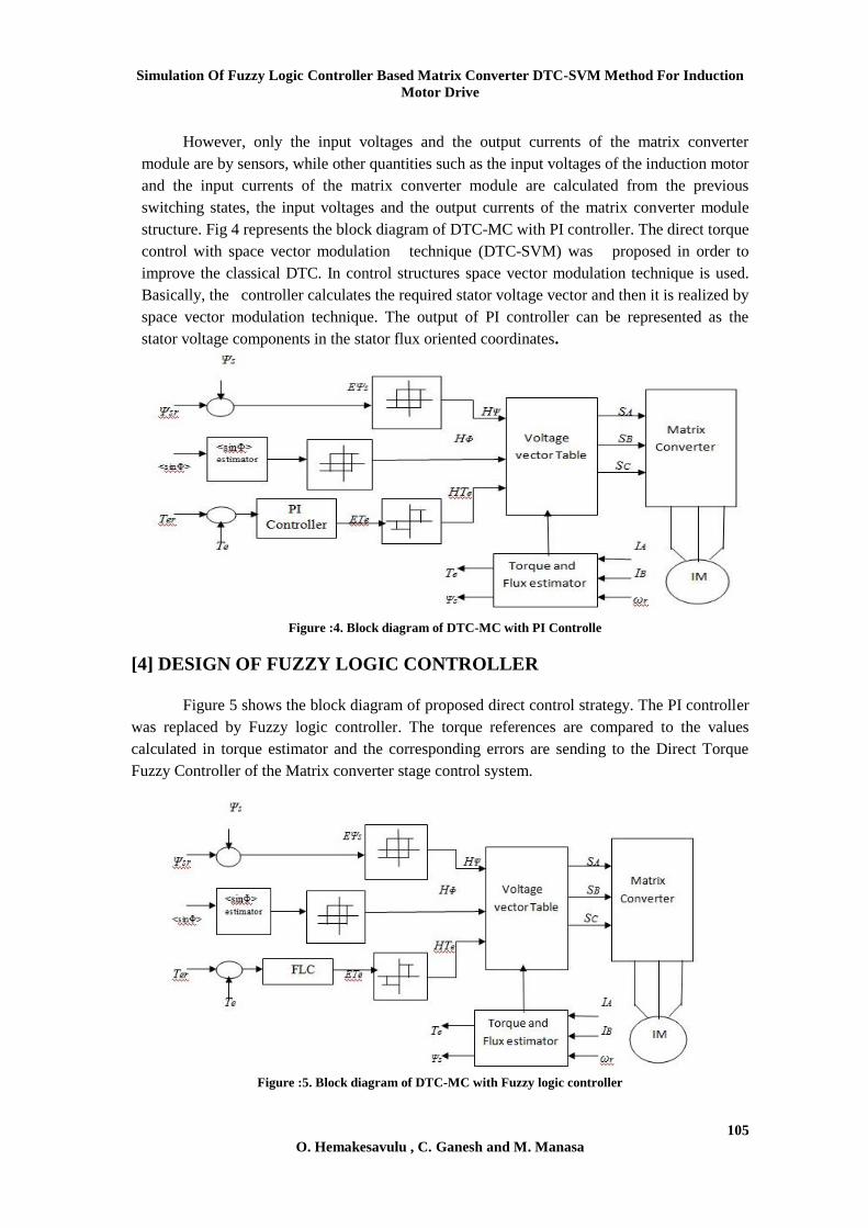
Figure 5 shows the block diagram of proposed direct control strategy. The PI controller
was replaced by Fuzzy logic controller. The torque references are compared to the values
calculated in torque estimator and the corresponding errors are sending to the Direct Torque
Fuzzy Controller of the Matrix converter stage control system.
Figure :5. Block diagram of DTC-MC with Fuzzy logic controller
International Journal of Computer Engineering and Applications, Volume VII, Issue III, Part I,
September 14
106 O. Hemakesavulu , C. Ganesh and M. Manasa
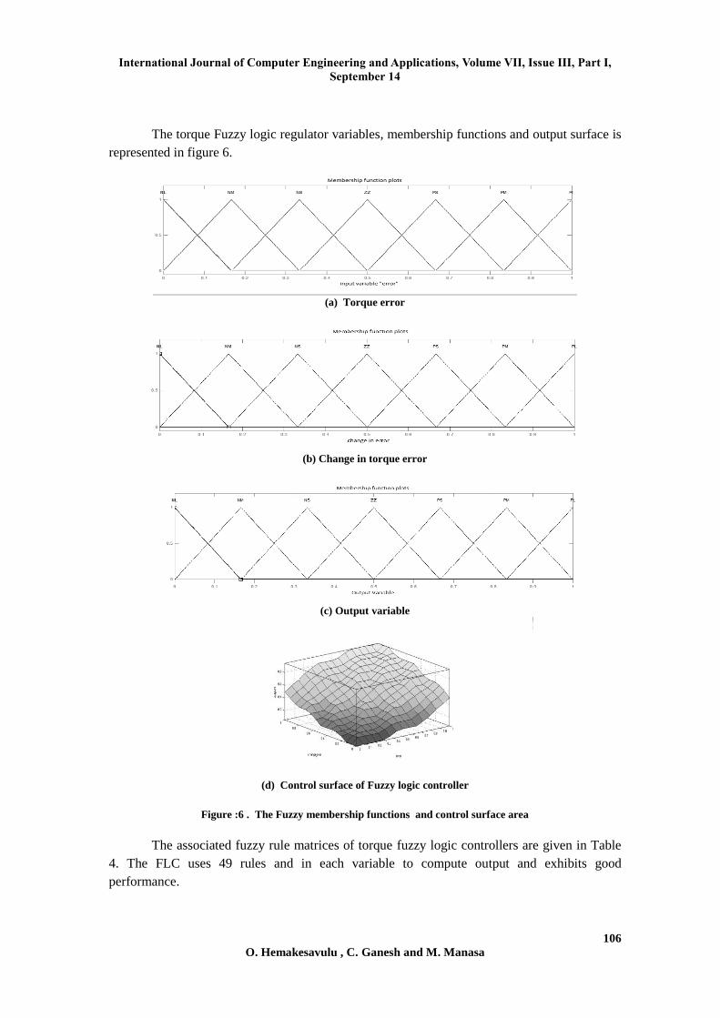
The torque Fuzzy logic regulator variables, membership functions and output surface is
represented in figure 6.
(a) Torque error
(b) Change in torque error
(c) Output variable
(d) Control surface of Fuzzy logic controller
Figure :6 . The Fuzzy membership functions and control surface area
The associated fuzzy rule matrices of torque fuzzy logic controllers are given in Table
4. The FLC uses 49 rules and in each variable to compute output and exhibits good
performance.
Simulation Of Fuzzy Logic Controller Based Matrix Converter DTC-SVM Method For Induction
Motor Drive
107 O. Hemakesavulu , C. Ganesh and M. Manasa
Table :3. Fuzzy control rule
The torque fuzzy controller also has two input variables and one output variable. Input
variables: torque error ET and change rate of torque error ΔET. Output variable: reference
voltage vector.
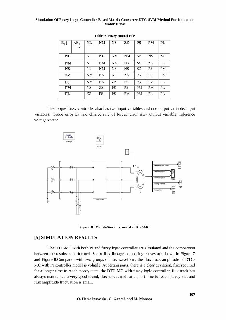
Figure :8 . Matlab/Simulink model of DTC-MC
[5] SIMULATION RESULTS
The DTC-MC with both PI and fuzzy logic controller are simulated and the comparison
between the results is performed. Stator flux linkage comparing curves are shown in Figure 7
and Figure 8.Compared with two groups of flux waveform, the flux track amplitude of DTC-
MC with PI controller model is volatile. At certain parts, there is a clear deviation, flux required
for a longer time to reach steady-state, the DTC-MC with fuzzy logic controller, flux track has
always maintained a very good round, flux is required for a short time to reach steady-stat and
flux amplitude fluctuation is small.
ET↓ ΔET
→
NL NM NS ZZ PS PM PL
NL NL NL NM NM NS NS ZZ
NM NL NM NM NS NS ZZ PS
NS NL NM NS NS ZZ PS PM
ZZ NM NS NS ZZ PS PS PM
PS NM NS ZZ PS PS PM PL
PM NS ZZ PS PS PM PM PL
PL ZZ PS PS PM PM PL PL

International Journal of Computer Engineering and Applications, Volume VII, Issue III, Part I,
September 14
108 O. Hemakesavulu , C. Ganesh and M. Manasa
Figure :7. Stator flux circle of DTC-MC with PI controller
Figure :8. Stator flux circle of DTC-MC with fuzzy Controller
From the above results a better response is obtained. However in DTC-MC with fuzzy
controller shown in fig 10 has less torque ripples when compared with DTC –MC with PI
controller (fig 8).
Figure :9. Torque response of DTC-MC with PI Controller
Figure :10. Torque response of DTC-MC with Fuzzy controller
Simulation Of Fuzzy Logic Controller Based Matrix Converter DTC-SVM Method For Induction
Motor Drive
109 O. Hemakesavulu , C. Ganesh and M. Manasa
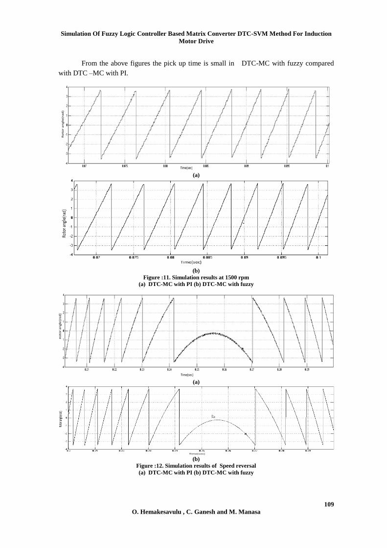
From the above figures the pick up time is small in DTC-MC with fuzzy compared
with DTC –MC with PI.
(a)
(b)
Figure :11. Simulation results at 1500 rpm
(a) DTC-MC with PI (b) DTC-MC with fuzzy
(a)
(b)
Figure :12. Simulation results of Speed reversal
(a) DTC-MC with PI (b) DTC-MC with fuzzy

International Journal of Computer Engineering and Applications, Volume VII, Issue III, Part I,
September 14
110 O. Hemakesavulu , C. Ganesh and M. Manasa
From the above results (fig 12) a good response is obtained for both methods with
speed reversal also. The DTC matrix converter with fuzzy controller has better performance
compared with PI controller.
[6] CONCLUSION
This paper presents a Direct Torque Control with Matrix Converter using fuzzy logic
controller method for induction motor. However the DTC method have combined with the
SVM method on matrix converter. The simulation results proved that transient torque response
is excellent. The DTC Matrix Converter with fuzzy controller has a better performance.
However Controlling of torque and reducing the torque ripples was the main goal, so the DTC
Matrix Converter with fuzzy controller possesses less ripples in compare DTC-MC with PI
controller.

Simulation Of Fuzzy Logic Controller Based Matrix Converter DTC-SVM Method For Induction
Motor Drive
111 O. Hemakesavulu , C. Ganesh and M. Manasa
REFERENCES
[1] Casadei, D; Profumo,F, ; Tani.,:A, FOC and DTC: Two viable schemes for induction
motors torque control, IEEE. Power Electron, vol. 17, No. 5, pp. 779-787, 2007.
[2] Buja, G. S. ; Kazmierkowski, M.P : Direct torque control of PWM Inverter-Fed AC
Motors-A survey, IEEE Trans. on Industrial Electronics, vol. 51, No. 4, pp. 744-758,
August 2008.
[3] Boldea ; Klumpner: Artificial loading of induction machine using a matrix converter, IEEE
Power electronics, No 475 , pp. 40-45, 2000.
[4] Alesina, A ; Venturini, M: Solid-state power conversion : A Fourier analysis approach to
generalized transformer synthesis, IEEE Trans. on circuit and systems, vol.cas-28, No 4.pp
319-330,1981.
[5] Chunyu Zhao ; Dayue Chen ; Xin Wei :A New direct torque control strategy of induction
motors based on duty ratio control technique, Proceedings of the Chinese Society for
Electrical Engineering, vol. 25, No. 5, pp. 93-97, 2008.
[6] Kang, J. K ; Sul, S. K: New Direct Torque Control of Induction Motor for Minimum
Torque Ripple and Constant Switching Frequency, IEEE Trans. Ind. App., vol. 35,no 5,
pp. 1076-1072, Sept./Oct. 1999.
[7] Elbuluk, M. E ;M ir, S : Precision troque control in Inverter-Fed induction machines using
fuzzy logic, Proceedings of the 26th IEEE Power Electronics Specialists Conference
(PESC), vol. 1, pp. 396-401, 2005.
[8] Qiang Liu ; Qing Hu ; Xiying Ding ; Xiaona Ma; Xiaoran He : The fuzzy torque control of
induction motorbased on space vector modulation, Third International Conference on
Natural Computation, 2009.
[9] Shimiao Hu ; Wenhui Cao ; Zhijun Jiang :A new fuzzy logic torque control scheme based
on vector control and direct torque control for induction machine, The 3rd
International
Conference on Innovative Computing Information, 2010.
[10] Cai, B.J ; Nian: A Novel MC-DTC Method for Induction Motor Based on Fuzzy-neural
Network Space Vector Modulation, JOURNAL OF SOFTWARE, VOL. 7, NO. 5, MAY
2012.
[11] Habetler, T.G ; Profumo, F ; Pastorelli, M; Tolbert, L.M : Direct Torque Control of
Induction Machines Using Space Vector Modulation, IEEE Trans. Ind. App. vol. 28, no. 5,
pp.1045-1054,Sep/Oct. 1992.
[12] Hu, H ; Li, Y :Predictive Direct Torque Control Strategies of Induction Motor Based on
Area Voltage Vectors Table, IEEE Ind. Elec. Society Conf. IECON, 2-6 Nov. 2003.
[13] Hu, H ;Wang,Y.Li.C : Predictive Control of Torque and Flux of Induction Motor Drives,
IEEE PEDS 2005.