Embed Size (px)
Citation preview
3416 JOURNAL OF LIGHTWAVE TECHNOLOGY, VOL. 26, NO. 20, OCTOBER 15, 2008
Compensation of Dispersion and NonlinearImpairments Using Digital Backpropagation
Ezra Ip and Joseph M. Kahn, Fellow, IEEE
Abstract—Optical fiber transmission is impacted by linear andnonlinear impairments. We study the use of digital backpropaga-tion (BP) in conjunction with coherent detection to jointly mitigatedispersion and fiber nonlinearity. We propose a noniterative asym-metric split-step Fourier method (SSFM) for solving the inversenonlinear Schrödinger equation (NLSE). Using simulation resultsfor RZ-QPSK transmitted over terrestrial systems with inline am-plification and dispersion compensation, we obtain heuristics forthe step size and sampling rate requirements, as well as the op-timal dispersion map.
Index Terms—Coherent detection, chromatic dispersion, digitalsignal processing, optical communications, optical Kerr effect,phase noise, phase shift keying.
I. INTRODUCTION
T RANSMISSION impairments in optical fiber can bedivided into two categories: linear impairments, which
include chromatic dispersion (CD), polarization-mode dis-persion (PMD), symbol timing offset, and optical filtering;and nonlinear impairments, which include laser phase noise,self-phase modulation (SPM), cross-phase modulation (XPM),four-wave mixing (FWM), and nonlinear phase noise (NLPN).Until recently, compensation techniques for different impair-ments have been considered separately. Digital equalization oflinear impairments using a fractionally spaced finite impulseresponse (FIR) filter was studied in [1]–[3], while digitalfeedforward carrier recovery to overcome laser phase noisewas studied in [4]–[7]. XPM has traditionally been mitigatedusing nonzero-dispersion fiber to induce pulse walkoff [8].Techniques for reducing the impact of NLPN have includedtransmitter-based electronic precompensation [9], optical phaseconjugation [10]–[12] and receiver-based electronic phaserotation [13].
Recently, backpropagation (BP) was proposed as a uni-versal technique for jointly compensating linear and nonlinearimpairments [14], [15]. BP involves solving an inverse non-linear Schrödinger equation (NLSE) through the fiber toestimate the transmitted signal. BP has been shown to enable
Manuscript received March 13, 2008; revised June 10, 2008. Current ver-sion published December 19, 2008. This work was supported in part by a NavalResearch Laboratory award N00173-06-1-G035 and by a Army Research Lab-oratory contract W911-QX-O6-C-0101 via a subcontract from CeLight, Inc.
The authors are with the Department of Electrical Engineering, Stan-ford University, Stanford, CA 94305 USA (e-mail: [email protected];[email protected]).
Color versions of one or more of the figures in this paper are available onlineat http://ieeexplore.ieee.org.
Digital Object Identifier 10.1109/JLT.2008.927791
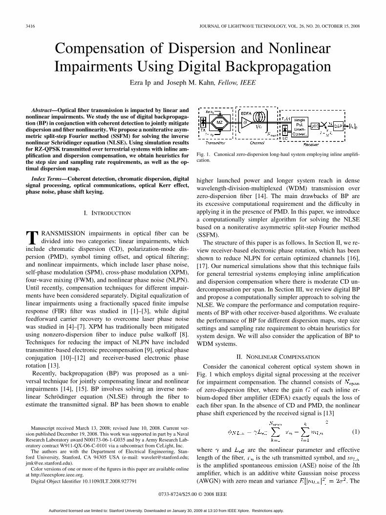
Fig. 1. Canonical zero-dispersion long-haul system employing inline amplifi-cation.
higher launched power and longer system reach in densewavelength-division-multiplexed (WDM) transmission overzero-dispersion fiber [14]. The main drawbacks of BP areits excessive computational requirement and the difficulty inapplying it in the presence of PMD. In this paper, we introducea computationally simpler algorithm for solving the NLSEbased on a noniterative asymmetric split-step Fourier method(SSFM).
The structure of this paper is as follows. In Section II, we re-view receiver-based electronic phase rotation, which has beenshown to reduce NLPN for certain optimized channels [16],[17]. Our numerical simulations show that this technique failsfor general terrestrial systems employing inline amplificationand dispersion compensation where there is moderate CD un-dercompensation per span. In Section III, we review digital BPand propose a computationally simpler approach to solving theNLSE. We compare the performance and computation require-ments of BP with other receiver-based algorithms. We evaluatethe performance of BP for different dispersion maps, step sizesettings and sampling rate requirement to obtain heuristics forsystem design. We will also consider the application of BP toWDM systems.
II. NONLINEAR COMPENSATION
Consider the canonical coherent optical system shown inFig. 1 which employs digital signal processing at the receiverfor impairment compensation. The channel consists ofof zero-dispersion fiber, where the gain of each inline er-bium-doped fiber amplifier (EDFA) exactly equals the loss ofeach fiber span. In the absence of CD and PMD, the nonlinearphase shift experienced by the received signal is [13]
(1)
where and are the nonlinear parameter and effectivelength of the fiber, is the th transmitted symbol, andis the amplified spontaneous emission (ASE) noise of the thamplifier, which is an additive white Gaussian noise process(AWGN) with zero mean and variance . The
0733-8724/$25.00 © 2008 IEEE
Authorized licensed use limited to: Stanford University. Downloaded on January 30, 2009 at 13:10 from IEEE Xplore. Restrictions apply.

IP AND KAHN: COMPENSATION OF DISPERSION AND NONLINEAR IMPAIRMENTS 3417
Fig. 2. Dispersion map and power profile for the experimental setups used by:(a) Kikuchi et al. [16]; and (b) Charlet et al. [17].
received signal has a spiral-shaped con-stellation [18]. It is possible to exploit the correlation betweenthe received amplitude and NL phase shift to reduce NLPNvariance. A simple compensation scheme is
(2)
where is the phase of the received signal, is acoefficient to be optimized, and is the corrected phase. [13]showed that the optimum value of is
(3)
which corresponds (in a mean sense) to derotating the receivedsignal by half the mean nonlinear phase shift . It hasbeen shown that this NLPN compensation scheme reducesNLPN variance by four: .
The ability of amplitude-dependent phase rotation to improvesystem performance has been demonstrated in [16] and [17].In both experiments, short fiber spans were used with nearlyperfect CD compensation per span. Fig. 2 shows the approxi-mate dispersion maps and power profiles used by the two ex-periments. It is observed that the local dispersion at any point inthe link is small, and peak power occurs when the accumulateddispersion is nearly zero, . Since fibernonlinearity has greatest effect at high power, in a first-order ap-proximation where we assume nonlinear effects are localized atthe points of peak power, (1) is a good model of NL phase. Con-sequently, the phase rotation algorithm is successful at reducingthe NLPN variance.
Fig. 3. Integrated digital coherent receivers for single-polarization transmis-sion, integrating the functions of downconversion and channel impairment com-pensation. These receivers show nonlinear compensation using: (a) amplitude-dependent phase rotation; and (b) digital BP.
The results of [16] and [17] suggests an integrated receivershown in Fig. 3(a) [19]. A single-polarization optoelectronicdownconverter recovers the analog inphase and quadrature com-ponents of the optical -field. Its output is passed through anantialiasing filter and then synchronously sampled at a rate
where is the symbol period and is aninteger fraction oversampling ratio. NLPN compensation is per-formed first, as (2) requires only the received amplitudes at thesampling instants. The derotated signal is then passed through afractionally spaced linear equalizer whose output is one sampleper symbol. Feedforward carrier recovery follows.
We simulated the performance of the receiver of Fig. 3(a) for21.4 Gb/s 50% RZ-QPSK1 over the transmission system shownin Fig. 4(a). We select this transmission model as it is represen-tative of long haul terrestrial systems with inline amplificationand dispersion compensation. The parameters of the link com-ponents used are shown in Table I. We assume the two EDFAshave equal gain that exactly compensate the signal attenuationby the SMF and DCF. We undercompensate CD by 10% perspan. At the receiver, no tunable dispersion compensation isused. Instead, residual CD is compensated using the fraction-ally spaced linear equalizer shown in Fig. 3(a), whose coeffi-cient are set in accordance with [2]. The antialiasing filteris a fifth-order Butterworth filter whose 3-dB cutoff frequencyis 40% of the sampling rate. In all simulations considered inthis paper, we neglect laser phase noise, focusing only on fiberimpairments. Feedforward carrier recovery is then reduced to aconstant phase rotation.
Fig. 5 shows the performance obtained for the integratedreceiver with and without the NLPN compensator, while thedotted curve is the theoretical AWGN limit of SNR.At low launched power, both systems have similar perfor-mances that approach the AWGN limit. At higher launchedpowers, nonlinear effects cause excess phase error variance.In contrast with the results of [16] and [17], the NLPN com-pensator does not improve system performance. In fact, worseresults were obtained compared to linear equalization only.Fig. 6(a) and (b) shows the equalized constellations forthe two algorithms when the launched power is 2 dBm. TheNLPN compensator fails because there are significant non-linear effects occurring at the start of each span of DCF, where
1We assume a raw information rate of 20 Gb/s with 7% overhead for Reed-Solomon coding.
Authorized licensed use limited to: Stanford University. Downloaded on January 30, 2009 at 13:10 from IEEE Xplore. Restrictions apply.
3418 JOURNAL OF LIGHTWAVE TECHNOLOGY, VOL. 26, NO. 20, OCTOBER 15, 2008
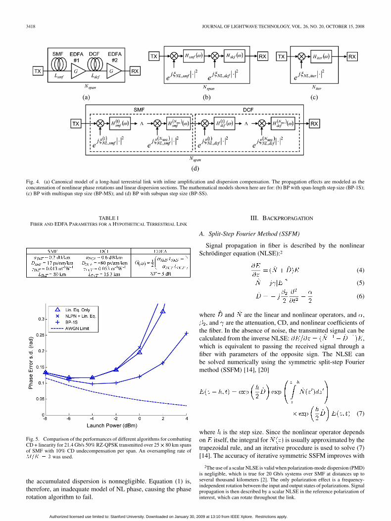
Fig. 4. (a) Canonical model of a long-haul terrestrial link with inline amplification and dispersion compensation. The propagation effects are modeled as theconcatenation of nonlinear phase rotations and linear dispersion sections. The mathematical models shown here are for: (b) BP with span-length step size (BP-1S);(c) BP with multispan step size (BP-MS); and (d) BP with subspan step size (BP-SS).
TABLE IFIBER AND EDFA PARAMETERS FOR A HYPOTHETICAL TERRESTRIAL LINK
Fig. 5. Comparison of the performances of different algorithms for combattingCD + linearity for 21.4 Gb/s 50% RZ-QPSK transmitted over 25� 80 km spansof SMF with 10% CD undecompensation per span. An oversampling rate ofM=K = 2 was used.
the accumulated dispersion is nonnegligible. Equation (1) is,therefore, an inadequate model of NL phase, causing the phaserotation algorithm to fail.
III. BACKPROPAGATION
A. Split-Step Fourier Method (SSFM)
Signal propagation in fiber is described by the nonlinearSchrödinger equation (NLSE):2
(4)
(5)
(6)
where and are the linear and nonlinear operators, and ,, and are the attenuation, CD, and nonlinear coefficients of
the fiber. In the absence of noise, the transmitted signal can becalculated from the inverse NLSE: ,which is equivalent to passing the received signal through afiber with parameters of the opposite sign. The NLSE canbe solved numerically using the symmetric split-step Fouriermethod (SSFM) [14], [20]
(7)
where is the step size. Since the nonlinear operator dependson itself, the integral for is usually approximated by thetrapezoidal rule, and an iterative procedure is used to solve (7)[14]. The accuracy of iterative symmetric SSFM improves with
2The use of a scalar NLSE is valid when polarization-mode dispersion (PMD)is negligible, which is true for 20 Gb/s systems over SMF at distances up toseveral thousand kilometers [2]. The only polarization effect is a frequency-independent rotation between the input and output states of polarizations. Signalpropagation is then described by a scalar NLSE in the reference polarization ofinterest, which can rotate throughout the link.
Authorized licensed use limited to: Stanford University. Downloaded on January 30, 2009 at 13:10 from IEEE Xplore. Restrictions apply.

IP AND KAHN: COMPENSATION OF DISPERSION AND NONLINEAR IMPAIRMENTS 3419
Fig. 6. Equalized constellations for 21.4 Gb/s 50% RZ-QPSK transmitted over 25� 80 km spans of SMF with 10% CD undecompensation per span at 0 dBmlaunched power. The algorithms used are: (a) linear equalization only; (b) NLPN compensation + linear equalization; and (c) BP-1S.
Fig. 7. (a) Fiber section from z to z + h. (b) Mathematical model.
Fig. 8. Matlab pseudocode for BP-1S.
increasing the number of iterations used to solve (7), and by de-creasing the step size. Both of these increase the computationalrequirement.
In this paper, we use a computationally less expensive algo-rithm based on a noniterative asymmetric SSFM where the fiberis modeled as a concatenation of nonlinear and linear sections.Simplified BP has previously been considered for electronic pre-compensation in [21]. Consider Fig. 7, where
(8)
and
(9)
We base this model on the heuristic that nonlinear effects arestrongest at the beginning of a fiber section where signal poweris highest. Thus, nonlinear phase rotation is performed first be-fore linear propagation. In the limit of being infinitesimallysmall, both the asymmetric SSFM and symmetric SSFM ap-proach the true NLSE solution. We observe from (8) and (9)that fiber impairments are primarily two phase effects: CD isa phase multiplication in the frequency domain, whereas Kerrnonlinearity is a phase multiplication in the time domain. Asboth of these operations are invertible, the NLSE is also invert-ible.
The (symmetric) SSFM has been successfully employed forsimulating the propagation of solitons. The step size require-ment for modeling communication systems was studied in [22].For signal detection however, it is not necessary to compute theNLSE to a high degree of accuracy: we merely need to makesmall enough so that numerical errors are small compared to theimpact of AWGN. In particular, ASE causes amplitude fluctua-tions so that the inversion of (8) results in derotation by a noisyphase proportional to . When solving an NLSE with manysections, noise causes the BP solution to diverge from the trueinput signal. This effect occurs regardless of the step size used.In the remainder of this section, we propose three choices ofstep size for digital BP and compare their usefulness. A digitalcoherent receiver implementing BP is shown in Fig. (3b). SinceBP corrects for both linear and nonlinear impairments, the adap-tive linear equalizer can be replaced with a fixed downsampler.
B. Backpropagation With Span-Length Step Size (BP-1S)
In our first approximation, we make the step size equal to thelength of a fiber span. The mathematical model of the channelis shown in Fig. (4b), where
(10)
(11)
(12)
(13)
The parameter in (12) and (13) needs to be opti-mized empirically, and its value depends on the dispersion map,launched power, and rate of oversampling. In pure BP,exactly inverts the nonlinear phase of the fiber, and is optimal inthe limit of high SNR. For the particular case of zero dispersionfiber (Section II), the optimal value of is 1/2.
We simulated the performance of BP-1S for 21.4 Gb/s 50%RZ-QPSK transmitted over the terrestrial channel considered inSection II. The input signal used is a random periodic sequencewith a block length of 32 768 symbols. Fig. 8 shows the pseu-docode for our BP-1S algorithm. The linear step of the SSFM iscomputed in the frequency domain using the fast Fourier trans-form (FFT). The long block length ensures almost perfect equal-ization of CD with negligible power penalty in the absence ofKerr nonlinearity, provided the oversampling rate is sufficiently
Authorized licensed use limited to: Stanford University. Downloaded on January 30, 2009 at 13:10 from IEEE Xplore. Restrictions apply.
3420 JOURNAL OF LIGHTWAVE TECHNOLOGY, VOL. 26, NO. 20, OCTOBER 15, 2008
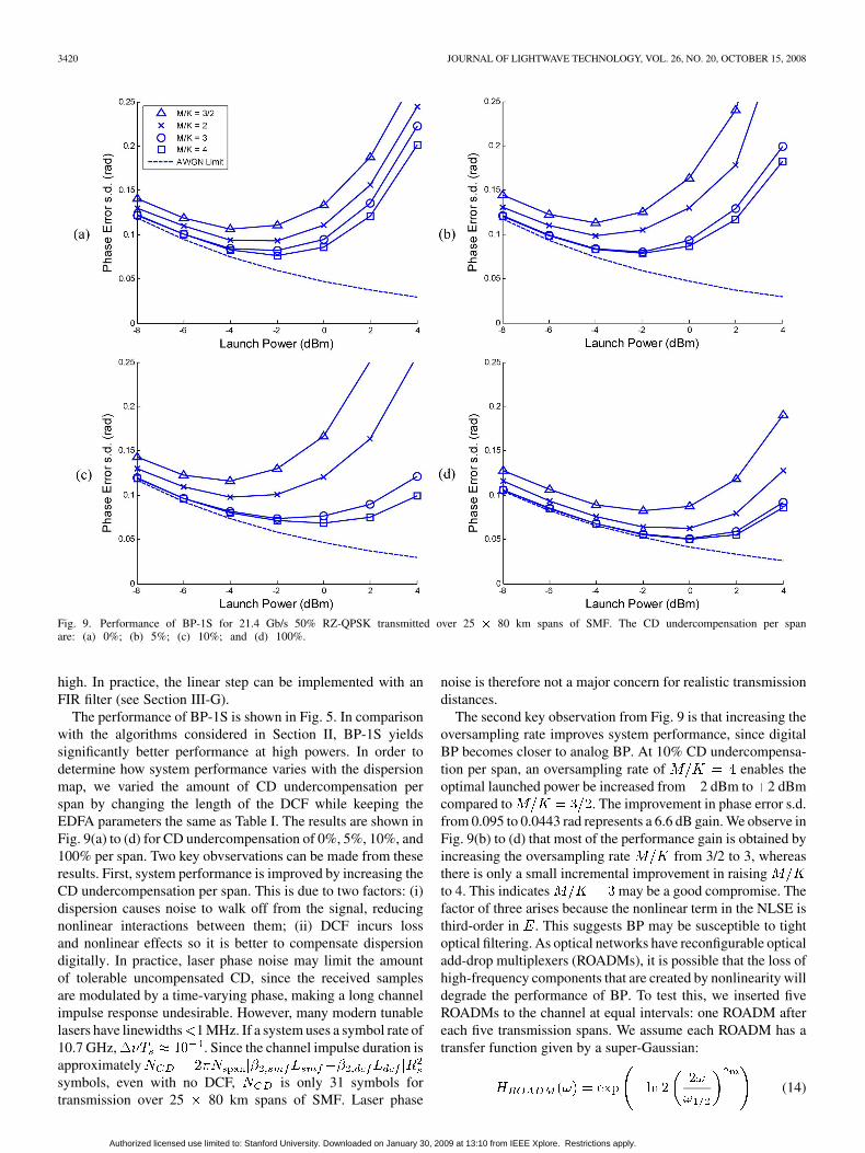
Fig. 9. Performance of BP-1S for 21.4 Gb/s 50% RZ-QPSK transmitted over 25 � 80 km spans of SMF. The CD undercompensation per spanare: (a) 0%; (b) 5%; (c) 10%; and (d) 100%.
high. In practice, the linear step can be implemented with anFIR filter (see Section III-G).
The performance of BP-1S is shown in Fig. 5. In comparisonwith the algorithms considered in Section II, BP-1S yieldssignificantly better performance at high powers. In order todetermine how system performance varies with the dispersionmap, we varied the amount of CD undercompensation perspan by changing the length of the DCF while keeping theEDFA parameters the same as Table I. The results are shown inFig. 9(a) to (d) for CD undercompensation of 0%, 5%, 10%, and100% per span. Two key obvservations can be made from theseresults. First, system performance is improved by increasing theCD undercompensation per span. This is due to two factors: (i)dispersion causes noise to walk off from the signal, reducingnonlinear interactions between them; (ii) DCF incurs lossand nonlinear effects so it is better to compensate dispersiondigitally. In practice, laser phase noise may limit the amountof tolerable uncompensated CD, since the received samplesare modulated by a time-varying phase, making a long channelimpulse response undesirable. However, many modern tunablelasers have linewidths 1 MHz. If a system uses a symbol rate of10.7 GHz, . Since the channel impulse duration isapproximatelysymbols, even with no DCF, is only 31 symbols fortransmission over 25 80 km spans of SMF. Laser phase
noise is therefore not a major concern for realistic transmissiondistances.
The second key observation from Fig. 9 is that increasing theoversampling rate improves system performance, since digitalBP becomes closer to analog BP. At 10% CD undercompensa-tion per span, an oversampling rate of enables theoptimal launched power be increased from 2 dBm to 2 dBmcompared to . The improvement in phase error s.d.from 0.095 to 0.0443 rad represents a 6.6 dB gain. We observe inFig. 9(b) to (d) that most of the performance gain is obtained byincreasing the oversampling rate from 3/2 to 3, whereasthere is only a small incremental improvement in raisingto 4. This indicates may be a good compromise. Thefactor of three arises because the nonlinear term in the NLSE isthird-order in . This suggests BP may be susceptible to tightoptical filtering. As optical networks have reconfigurable opticaladd-drop multiplexers (ROADMs), it is possible that the loss ofhigh-frequency components that are created by nonlinearity willdegrade the performance of BP. To test this, we inserted fiveROADMs to the channel at equal intervals: one ROADM aftereach five transmission spans. We assume each ROADM has atransfer function given by a super-Gaussian:
(14)
Authorized licensed use limited to: Stanford University. Downloaded on January 30, 2009 at 13:10 from IEEE Xplore. Restrictions apply.
IP AND KAHN: COMPENSATION OF DISPERSION AND NONLINEAR IMPAIRMENTS 3421
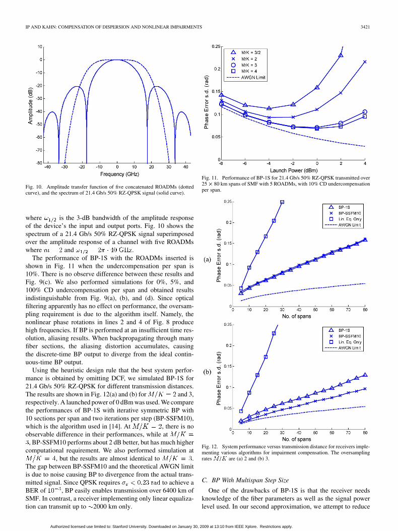
Fig. 10. Amplitude transfer function of five concatenated ROADMs (dottedcurve), and the spectrum of 21.4 Gb/s 50% RZ-QPSK signal (solid curve).
where is the 3-dB bandwidth of the amplitude responseof the device’s the input and output ports. Fig. 10 shows thespectrum of a 21.4 Gb/s 50% RZ-QPSK signal superimposedover the amplitude response of a channel with five ROADMswhere and .
The performance of BP-1S with the ROADMs inserted isshown in Fig. 11 when the undercompensation per span is10%. There is no observe difference between these results andFig. 9(c). We also performed simulations for 0%, 5%, and100% CD undercompensation per span and obtained resultsindistinguishable from Fig. 9(a), (b), and (d). Since opticalfiltering apparently has no effect on performance, the oversam-pling requirement is due to the algorithm itself. Namely, thenonlinear phase rotations in lines 2 and 4 of Fig. 8 producehigh frequencies. If BP is performed at an insufficient time res-olution, aliasing results. When backpropagating through manyfiber sections, the aliasing distortion accumulates, causingthe discrete-time BP output to diverge from the ideal contin-uous-time BP output.
Using the heuristic design rule that the best system perfor-mance is obtained by omitting DCF, we simulated BP-1S for21.4 Gb/s 50% RZ-QPSK for different transmission distances.The results are shown in Fig. 12(a) and (b) for and 3,respectively. A launched power of 0 dBm was used. We comparethe performances of BP-1S with iterative symmetric BP with10 sections per span and two iterations per step (BP-SSFM10),which is the algorithm used in [14]. At , there is noobservable difference in their performances, while at
, BP-SSFM10 performs about 2 dB better, but has much highercomputational requirement. We also performed simulation at
, but the results are almost identical to .The gap between BP-SSFM10 and the theoretical AWGN limitis due to noise causing BP to divergence from the actual trans-mitted signal. Since QPSK requires to achieve aBER of , BP easily enables transmission over 6400 km ofSMF. In contrast, a receiver implementing only linear equaliza-tion can transmit up to 2000 km only.
Fig. 11. Performance of BP-1S for 21.4 Gb/s 50% RZ-QPSK transmitted over25� 80 km spans of SMF with 5 ROADMs, with 10% CD undercompensationper span.
Fig. 12. System performance versus transmission distance for receivers imple-menting various algorithms for impairment compensation. The oversamplingrates M=K are (a) 2 and (b) 3.
C. BP With Multispan Step Size
One of the drawbacks of BP-1S is that the receiver needsknowledge of the fiber parameters as well as the signal powerlevel used. In our second approximation, we attempt to reduce
Authorized licensed use limited to: Stanford University. Downloaded on January 30, 2009 at 13:10 from IEEE Xplore. Restrictions apply.
3422 JOURNAL OF LIGHTWAVE TECHNOLOGY, VOL. 26, NO. 20, OCTOBER 15, 2008
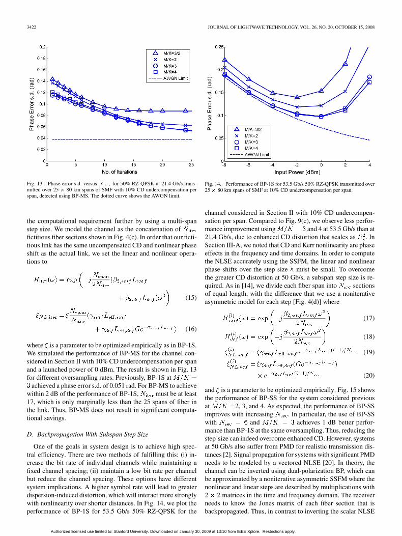
Fig. 13. Phase error s.d. versus N for 50% RZ-QPSK at 21.4 Gb/s trans-mitted over 25 � 80 km spans of SMF with 10% CD undercompensation perspan, detected using BP-MS. The dotted curve shows the AWGN limit.
the computational requirement further by using a multi-spanstep size. We model the channel as the concatenation offictitious fiber sections shown in Fig. 4(c). In order that our ficti-tious link has the same uncompensated CD and nonlinear phaseshift as the actual link, we set the linear and nonlinear opera-tions to
(15)
(16)
where is a parameter to be optimized empirically as in BP-1S.We simulated the performance of BP-MS for the channel con-sidered in Section II with 10% CD undercompensation per spanand a launched power of 0 dBm. The result is shown in Fig. 13for different oversampling rates. Previously, BP-1S at
achieved a phase error s.d. of 0.051 rad. For BP-MS to achievewithin 2 dB of the performance of BP-1S, must be at least17, which is only marginally less than the 25 spans of fiber inthe link. Thus, BP-MS does not result in significant computa-tional savings.
D. Backpropagation With Subspan Step Size
One of the goals in system design is to achieve high spec-tral efficiency. There are two methods of fulfilling this: (i) in-crease the bit rate of individual channels while maintaining afixed channel spacing; (ii) maintain a low bit rate per channelbut reduce the channel spacing. These options have differentsystem implications. A higher symbol rate will lead to greaterdispersion-induced distortion, which will interact more stronglywith nonlinearity over shorter distances. In Fig. 14, we plot theperformance of BP-1S for 53.5 Gb/s 50% RZ-QPSK for the
Fig. 14. Performance of BP-1S for 53.5 Gb/s 50% RZ-QPSK transmitted over25 � 80 km spans of SMF at 10% CD undercompensation per span.
channel considered in Section II with 10% CD undercompen-sation per span. Compared to Fig. 9(c), we observe less perfor-mance improvement using and 4 at 53.5 Gb/s than at21.4 Gb/s, due to enhanced CD distortion that scales as . InSection III-A, we noted that CD and Kerr nonlinearity are phaseeffects in the frequency and time domains. In order to computethe NLSE accurately using the SSFM, the linear and nonlinearphase shifts over the step size must be small. To overcomethe greater CD distortion at 50 Gb/s, a subspan step size is re-quired. As in [14], we divide each fiber span into sectionsof equal length, with the difference that we use a noniterativeasymmetric model for each step [Fig. 4(d)] where
(17)
(18)
(19)
(20)
and is a parameter to be optimized empirically. Fig. 15 showsthe performance of BP-SS for the system considered previousat 2, 3, and 4. As expected, the performance of BP-SSimproves with increasing . In particular, the use of BP-SSwith and achieves 1 dB better perfor-mance than BP-1S at the same oversampling. Thus, reducing thestep-size can indeed overcome enhanced CD. However, systemsat 50 Gb/s also suffer from PMD for realistic transmission dis-tances [2]. Signal propagation for systems with significant PMDneeds to be modeled by a vectored NLSE [20]. In theory, thechannel can be inverted using dual-polarization BP, which canbe approximated by a noniterative asymmetric SSFM where thenonlinear and linear steps are described by multiplications with2 2 matrices in the time and frequency domain. The receiverneeds to know the Jones matrix of each fiber section that isbackpropagated. Thus, in contrast to inverting the scalar NLSE
Authorized licensed use limited to: Stanford University. Downloaded on January 30, 2009 at 13:10 from IEEE Xplore. Restrictions apply.

IP AND KAHN: COMPENSATION OF DISPERSION AND NONLINEAR IMPAIRMENTS 3423
Fig. 15. Performance of BP-SS for 53.5 Gb/s 50% RZ-QPSK transmitted over 25 � 80 km spans of SMF with 10% CD undercompensation per span. T Theoversampling rates M=K are: (a) 2; (b) 3; and (c) 4.
Fig. 16. Simulation of a three-channel WDM system. The input 21.4 Gb/s 50% RZ-QPSK signals are combined using an AWG whose channel bandwidths are80% of the channel spacing.
which depends on only two parameters ( and ), BP forthe general vectored NLSE requires knowledge of the PSP andDGD of every fiber section. The number of time-varying param-eters that need to be estimated becomes unrealistically large.
E. WDM
Since PMD is significant at symbol rates above 10 Gsymbol/sand is likely to render BP at 25 Gsymbol/s infeasible, it be-comes difficult to increase spectral efficiency by holding thechannel spacing at 50 GHz and increasing the symbol rate perchannel. A more realistic approach to increase spectral effi-ciency without increasing the SNR requirement is to decreasethe channel spacing, which enhances XPM. To estimate theimpact of XPM on performance, we performed a three-channelsimulation whose system model shown in Fig. 16. Threeindependent, copolarized channels modulated by 21.4 Gb/s50% RZ-QPSK data are multiplexed using an arrayed wave-guide grating (AWG). The baseband amplitude response ofthe AWG for each channel is assumed to be super-Gaussian:
with and, i.e., a 3-dB bandwidth equal to 80% of the
channel spacing. We selected a launched power of 0 dBm foreach channel. The WDM signal is transmitted over 25 80 kmspans of SMF with inline amplification only. DCF was omittedas per Section III-B. At the receiver, the LO laser frequency istuned to that of the center channel. The analog output of thedownconverter is filtered by a Butterworth filter whose 3-dBbandwidth is equal to 40% of the sampling rate. For our simu-lation, we used . Fig. 17 shows the change in systemperformance with channel spacing. We observe that BP-1S
gives the same performance as iterative symmetric BP, whilevastly outperforming linear equalization only. The referencecurve labeled “AWGN Crosstalk” denotes back-to-backperformance where AWGN of the appropriate power spectraldensity equal to the sum of all the EDFAs was added to thetransmitted signal, which was then detected without using BP.The gap between AWGN Crosstalk and the AWGN limit isthe result of linear crosstalk between channels, whereas the gapbetween BP and AWGN + Crosstalk is the result of nonlineareffects. System performance becomes significantly poorerwhen channel spacing is reduced below 25 GHz, largely due tolinear crosstalk.
F. Adaptative Backpropagation
In the BP algorithms considered—even for BP-1S andBP-MS—knowledge of the fiber parameters and signal powerlevels is required by the receiver. Since these parameters maynot be known in advance, and in reconfigurable systems, thelink may be time varying, it is desirable that BP be madeadaptive.
Consider single-polarization transmission with no DCFwhere PMD is negligible. Assuming the fiber spans are iden-tical, BP depends on only two parameters: and .It is possible for the receiver to perform BP using differenttrial values of these parameters, measuring the resulting phaseerror variance to determine the pair of parameters that givesthe best results. Fig. 18 shows the output phase error s.d. forBP-1S when and are perturbed about their optimumvalues. The performance surface is bowl shaped. One possibleadaptive algorithm is to initially set the receiver to perform
Authorized licensed use limited to: Stanford University. Downloaded on January 30, 2009 at 13:10 from IEEE Xplore. Restrictions apply.

3424 JOURNAL OF LIGHTWAVE TECHNOLOGY, VOL. 26, NO. 20, OCTOBER 15, 2008
Fig. 17. System performance vs. channel spacing for a three-channel WDMsystem transmitted over 25� 80 km of SMF with no DCF. Each channel trans-mits 50% RZ-QPSK data at 21.4 Gb/s and 0 dBm power.
Fig. 18. Performance surface obtained for BP-1S when the linear and nonlinearparameters of the algorithm are perturbed about their optimum values. These re-sults were obtained for single-channel 50% RZ-QPSK at 21.4 Gb/s transmittedover �80 km of SMF with no DCF.
linear equalization only [Fig. 3(a) without the NLPN com-pensation section], and adapting the coefficients of the filterwith a well-known algorithm like least-mean squares (LMS).The filter taps will converge to a solution that approximatelyinverts the dispersion of the channel. Upon taking the phaseof the FFT of the filter coefficients, an estimate of the link’s
is obtained. The receiver can then begin detection usingBP-1S with the linear coefficient found, and the parameter ofthe nonlinear stage can be adjusted until the lowest phase errors.d. is measured.
G. Computation Requirement
Finally, we compare the copmutation requirements of BP-1Sand linear equalization. We consider single-channel 50%RZ-QPSK at 21.4 Gb/s transmitted over 25 80 km spans ofSMF (no DCF) at a launched power of 0 dBm. In a real-time
Fig. 19. Performance of BP-1S versus length of the linear filter for 21.4 Gb/s50% RZ-QPSK transmitted over 25 � 80 km spans of SMF with no DCF. Thesignal launched power is 0 dBm.
implementation, we replace the FFT in Fig. 8 with a linearfilter of length . Assuming is even, we set the filtercoefficients to
for (21)
Fig. 19 shows the output phase error s.d. versus . In order toachieve performance within 2 dB of that of using an FFT withvery long block length [Fig. 9(d)], 70 filter taps are required.The computation requirement is as follows: since one complexmultiply is equal to four real multiplies, the linear step requires
real multiplications. In the nonlinear step, the squaredmagnitude function requires two real multiplies, while multipli-cation by requires another multiply. The exponential func-tion is assumed to be implemented with a lookup table. Finally,four real multiplies are required to compute the phase-rotatedoutput. For a link with of fiber, the total complexity is
real multiplications per symbol. Inthe hypothetical system considered in Fig. 19, this correspondsto 21 515 real multiplications per symbol.
Conversely, it was shown in [2] that neglecting non-linear effects, a fractionally spaced linear equalizer requires
taps to compensateCD with low power penalty, and an oversampling rate of
is sufficient. For our hypothetical system, thecomplexity requirement is only real mul-tiplications per symbol. An block-based FFT implementationcan further reduce the computation requirement further [19].Therefore, even with our reduced complexity algorithm basedon a noniterative asymmetric SSFM, BP-1S requires 100times more operations per symbol than linear equalization only.However, linear equalization achieves a phase error s.d. of 0.14rad, and is almost 7 dB worse than BP-1S. When DCF is used,the impulse response duration of the channel is shortened. This
Authorized licensed use limited to: Stanford University. Downloaded on January 30, 2009 at 13:10 from IEEE Xplore. Restrictions apply.

IP AND KAHN: COMPENSATION OF DISPERSION AND NONLINEAR IMPAIRMENTS 3425
reduces the computational requirement of linear equalizationstill further, but not for BP.
IV. CONCLUSION
We studied receiver-based digital signal processing al-gorithms for the joint compensation of linear and nonlinearimpairments in fiber. In long-haul terrestrial systems employinginline amplification and dispersion compenation, linear andnonlinear impairments are intertwined and cannot be compen-sated separately at the receiver. BP is a universal technique thatenables the joint mitigation of linear and nonlinear impairmentsfor an arbitrary channel. BP requires solving the inverse NLSEfor the channel and is computationally expensive. We studied areduced-complexity algorithm employing a noniterative asym-metric split-step Fourier method (SSFM). Our results showedthat using a step size equal to the length of a fiber span is areasonable compromise between performance and computa-tional requirement for a symbol rate of 10 Gsymbol/s, wherePMD is negligible. We found that the best system performanceis obtained by omitting the use of dispersion-compensationfiber (DCF), as CD can be compensated digitally without in-curring loss or nonlinear effects. For good numerical accuracy,digital BP should be performed at three-times oversampling.Using these empirical system design rules, we found that BPenables RZ-QPSK transmission over distances greater than6400 km, whereas a receiver implementing linear equalizationcan transmit 2000 km only. BP is not suitable for systems withsignificant PMD, as it is infeasible for the receiver to estimatethe Jones matrix of all fiber sections to be backpropagated. Thisrenders BP unsuitable for transmission at 25 Gsymbol/s wherePMD is nonnegligible over realistic transmission distances. Toincrease spectral efficiency, it is more desirable to use a lowerdata rate per channel with narrower channel spacing than toincrease the symbol rate while keeping the channel spacingfixed at 50 GHz.
REFERENCES
[1] J. Winters, “Equalization in coherent lightwave systems using afractionally spaced equalizer,” J. Lightw. Technol., vol. 8, no. 10, pp.1487–1491, Oct. 1990.
[2] E. Ip and J. M. Kahn, “Digital equalization of chromatic dispersion andpolarization mode dispersion,” J. Lightw. Technol., vol. 25, no. 8, pp.2033–2043, Aug. 2007.
[3] S. J. Savory, G. Gavioli, R. I. Killey, and P. Bayvel, “Electronic com-pensation of chromatic dispersion using a digital coherent receiver,”Opt. Expr., vol. 15, no. 5, pp. 2120–2126, March 2007.
[4] M. G. Taylor, “Accurate digital phase estimation process for coherentdetection using a parallel digital processor,” presented at the Proc.European Conference on Optical Communication (ECOC 2005),,Glasgow, U.K., 2005, Paper Tu4.2.6, unpublished.
[5] D.-S. Ly-Gagnon, S. Tsukamoto, K. Katoh, and K. Kikuchi, “Coherentdetection of optical quadrature phase-shift keying signals with carrierphase estimation,” J. Lightw. Technol., vol. 24, no. 1, pp. 12–21, Jan.2006.
[6] K. Kikuchi, “Phase-diversity homodyne detection of multilevel opticalmodulation with digital carrier phase estimation,” IEEE J. Sel. TopicsQuantum Electron., vol. 12, no. 4, pp. 563–570, Jul.–Aug. 2006.
[7] E. Ip and J. M. Kahn, “Feedforward carrier recovery for coherentoptical communications,” J. Lightw. Technol., vol. 25, no. 9, pp.2675–2692, Sep. 2007.
[8] M. Shtaif, E. Eiselt, and L. D. Garret, “Cross-phase modulationdistortion measurements in multispan WDM systems,” IEEE Photon.Technol. Lett., vol. 12, no. 1, pp. 88–90, Jan. 2000.
[9] K. Roberts, C. Li, L. Strawczynski, M. O’Sullivan, and I. Hardcastle,“Electronic precompensation of optical nonlinearity,” IEEE Photon.Technol. Lett., vol. 18, no. 2, pp. 403–405, Jan. 2006.
[10] A. Chowdhury and R.-J. Essiambre, “Optical phase conjugation andpseudolinear transmission,” Opt. Lett., vol. 29, no. 10, pp. 1105–1107,May 2004.
[11] P. Minzioni, I. Cristani, V. Degiorgio, L. Marazzi, M. Martinelli, C.Langrock, and M. M. Fejer, “Experimental demonstration of nonlin-earity and dispersion compensation in an embedded link by opticalphase conjugation,” IEEE Photon. Technol. Lett., vol. 18, no. 9, pp.995–997, May 2006.
[12] S. Kumar and L. Liu, “Reduction of nonlinear phase noise using opticalphase conjugation in quasi-linear optical transmission,” Opt. Expr., vol.15, no. 5, pp. 2166–2177, Mar. 2007.
[13] K.-P. Ho and J. M. Kahn, “Electronic compensation technique to mit-igate nonlinear phase noise,” J. Lightw. Technol., vol. 22, no. 3, pp.779–783, Mar. 2004.
[14] X. Li, X. Chen, G. Goldfarb, E. Mateo, I. Kim, F. Yaman, and G.Li, “Electronic post-compensation of WDM transmission impairmentsusing coherent detection and digital signal processing,” Opt. Expr., vol.16, no. 2, pp. 881–888, Jan. 2008.
[15] W. Shieh, H. Bao, and Y. Tang, “Coherent optical OFDM: Theory anddesign,” Opt. Expr., vol. 16, no. 2, pp. 841–859, Jan. 2008.
[16] K. Kikuchi, M. Fukase, and S. Kim, “Electronic post-compensationfor nonlinear phase noise in a 1000-km 20-Gb/s optical QPSK trans-mission system using the homodyne receiver with digital signal pro-cessing,” presented at the Proc. Opt. Fiber Commun. Conf. (OFC’ 07),Los Angeles, CA, 2007, Paper OTuA2, unpublished.
[17] G. Charlet, N. Maaref, J. Renaudier, H. Mardoyan, P. Tran, and S. Bigo,“Transmission of 40 Gb/s QPSK with coherent detection over ultra-long distance improved by nonlinearity mitigation,” presented at theProc. European Conference on Optical Communication (ECOC 2006),Cannes, France, 2006, Paper Th4.3.4, unpublished.
[18] A. P. T. Lau and J. M. Kahn, “Signal design and detection in pres-ence of nonlinear phase noise,” J. Lightw. Technol., vol. 25, no. 10, pp.3008–3016, Oct. 2007.
[19] E. Ip, A. P. T. Lau, D. J. Barros, and J. M. Kahn, “Coherent detectionin optical fiber systems,” Opt. Expr., vol. 16, no. 2, pp. 753–791, Jan.2008.
[20] G. P. Agrawal, Nonlinear Fiber Optics, 2nd ed. London, U.K.: Aca-demic, 1995.
[21] X. Liu and D. A. Fishman, “A fast and reliable algorithm for electronicpreequalization of SPM and chromatic dispersion,” presented at theProc. Opt. Fiber Commun. Conf. (OFC’ 06), Los Angeles, CA, 2006,Paper OThD4, unpublished.
[22] O. Sinkin, R. Holzlöhner, J. Zweck, and C. Menyuk, “Optimizationof the split-step Fourier method in modeling optical-fiber communica-tions systems,” J. Lightw. Technol., vol. 21, no. 1, pp. 61–68, 2003.
Ezra Ip received the B.E. (Hons.) degree in electrical and electronics engi-neering from the University of Canterbury in 2002, and the M.S. degree in elec-trical engineering from Stanford University, Standord, CA, in 2004. He is cur-rently pursuing the Ph.D. degree in electrical engineering at Stanford University.
In 2002, he was a Research Engineer with Industrial Research Ltd., NewZealand. His research interests include single-mode optical fiber communica-tions, free-space optical communications, and nonlinear optics.
Joseph M. Kahn (M’90–SM’98–F’00) received the A.B., M.A., and Ph.D. de-grees in physics from the University of California (UC), Berkeley, in 1981, 1983,and 1986, respectively.
From 1987 to 1990, he was with AT&T Bell Laboratories, Crawford HillLaboratory, Holmdel, NJ. He demonstrated multi-Gb/s coherent optical fibertransmission systems, setting world records for receiver sensitivity. From 1990to 2003, he was with the Department of Electrical Engineering and ComputerSciences at UC Berkeley, performing research on optical and wireless communi-cations. In 2000, he helped found StrataLight Communications, where he servedas Chief Scientist from 2000 to 2003. Since 2003, he has been a Professor ofElectrical Engineering with Stanford University. His current research interestsinclude single- and multimode optical fiber communications, free-space opticalcommunications, and MEMS for optical communications.
Prof. Kahn received the National Science Foundation Presidential Young In-vestigator Award in 1991. From 1993 to 2000, he served as a Technical Editorof IEEE Personal Communications Magazine.
Authorized licensed use limited to: Stanford University. Downloaded on January 30, 2009 at 13:10 from IEEE Xplore. Restrictions apply.