Embed Size (px)
Citation preview
Air and Check Valvesfor water and wastewater applications

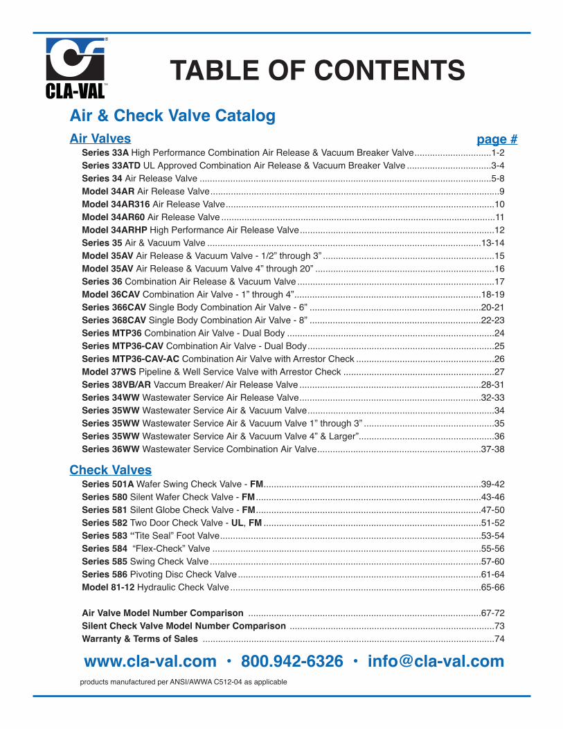
Air & Check Valve Catalog
Air Valves Series 33A High Performance Combination Air Release & Vacuum Breaker Valve..............................1-2
Series 33ATD UL Approved Combination Air Release & Vacuum Breaker Valve .................................3-4 Series 34 Air Release Valve ..................................................................................................................5-8 Model 34AR Air Release Valve.................................................................................................................9 Model 34AR316 Air Release Valve.........................................................................................................10 Model 34AR60 Air Release Valve ...........................................................................................................11 Model 34ARHP High Performance Air Release Valve............................................................................12 Series 35 Air & Vacuum Valve ...........................................................................................................13-14 Model 35AV Air Release & Vacuum Valve - 1/2” through 3” ...................................................................15 Model 35AV Air Release & Vacuum Valve 4” through 20” ......................................................................16 Series 36 Combination Air Release & Vacuum Valve .............................................................................17 Model 36CAV Combination Air Valve - 1” through 4”.........................................................................18-19 Series 366CAV Single Body Combination Air Valve - 6” ...................................................................20-21 Series 368CAV Single Body Combination Air Valve - 8” ...................................................................22-23 Series MTP36 Combination Air Valve - Dual Body .................................................................................24 Series MTP36-CAV Combination Air Valve - Dual Body.........................................................................25 Series MTP36-CAV-AC Combination Air Valve with Arrestor Check ......................................................26 Model 37WS Pipeline & Well Service Valve with Arrestor Check ...........................................................27 Series 38VB/AR Vaccum Breaker/ Air Release Valve .......................................................................28-31 Series 34WW Wastewater Service Air Release Valve.......................................................................32-33 Series 35WW Wastewater Service Air & Vacuum Valve.........................................................................34 Series 35WW Wastewater Service Air & Vacuum Valve 1” through 3” ...................................................35 Series 35WW Wastewater Service Air & Vacuum Valve 4” & Larger”.....................................................36 Series 36WW Wastewater Service Combination Air Valve................................................................37-38
Check Valves Series 501A Wafer Swing Check Valve - FM.....................................................................................39-42 Series 580 Silent Wafer Check Valve - FM ........................................................................................43-46 Series 581 Silent Globe Check Valve - FM........................................................................................47-50 Series 582 Two Door Check Valve - UL, FM .....................................................................................51-52 Series 583 “Tite Seal” Foot Valve......................................................................................................53-54 Series 584 “Flex-Check” Valve .........................................................................................................55-56 Series 585 Swing Check Valve ..........................................................................................................57-60 Series 586 Pivoting Disc Check Valve ...............................................................................................61-64 Model 81-12 Hydraulic Check Valve ..................................................................................................65-66
Air Valve Model Number Comparison ...........................................................................................67-72 Silent Check Valve Model Number Comparison ................................................................................73 Warranty & Terms of Sales ..................................................................................................................74
www.cla-val.com • 800.942-6326 • [email protected]
TABLE OF CONTENTS
page #
products manufactured per ANSI/AWWA C512-04 as applicable
33A High PerformanceCombination Air Release& Vacuum Breaker Valvewith a Series TD ThrottlingAir Control Device
FLOW
Well Casing
Pump ColumnAir Line
AirlineGauge
581Check Valve
Meter Blow-OffTee and
Valve
MainGateValve
SampleCock
Shut-Off Valve
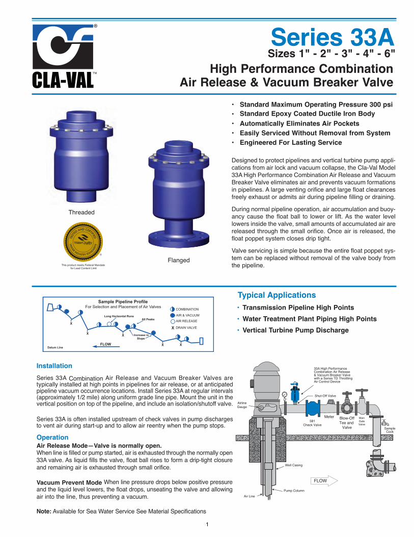
High Performance CombinationAir Release & Vacuum Breaker Valve
Operation
Air Release Mode—Valve is normally open.When line is filled or pump started, air is exhausted through the normally open33A valve. As liquid fills the valve, float ball rises to form a drip-tight closureand remaining air is exhausted through small orifice.
Vacuum Prevent Mode When line pressure drops below positive pressureand the liquid level lowers, the float drops, unseating the valve and allowingair into the line, thus preventing a vacuum.
Note: Available for Sea Water Service See Material Specifications
Installation
Series 33A Combination Air Release and Vacuum Breaker Valves aretypically installed at high points in pipelines for air release, or at anticipatedpipeline vacuum occurrence locations. Install Series 33A at regular intervals(approximately 1/2 mile) along uniform grade line pipe. Mount the unit in thevertical position on top of the pipeline, and include an isolation/shutoff valve.
Series 33A is often installed upstream of check valves in pump dischargesto vent air during start-up and to allow air reentry when the pump stops.
Sizes 1" - 2" - 3" - 4" - 6"
• Standard Maximum Operating Pressure 300 psi
• Standard Epoxy Coated Ductile Iron Body
• Automatically Eliminates Air Pockets
• Easily Serviced Without Removal from System
• Engineered For Lasting Service
Designed to protect pipelines and vertical turbine pump appli-cations from air lock and vacuum collapse, the Cla-Val Model33A High Performance Combination Air Release and VacuumBreaker Valve eliminates air and prevents vacuum formationsin pipelines. A large venting orifice and large float clearancesfreely exhaust or admits air during pipeline filling or draining.
During normal pipeline operation, air accumulation and buoy-ancy cause the float ball to lower or lift. As the water levellowers inside the valve, small amounts of accumulated air arereleased through the small orifice. Once air is released, thefloat poppet system closes drip tight.
Valve servicing is simple because the entire float poppet sys-tem can be replaced without removal of the valve body fromthe pipeline.
Series 33A
Flanged
Threaded
• Transmission Pipeline High Points
• Water Treatment Plant Piping High Points
• Vertical Turbine Pump Discharge
Typical ApplicationsSample Pipeline Profile
For Selection and Placement of Air Valves
Long Horizontal RunsAll Peaks
Increase in Slope
Datum Line
COMBINATION
AIR & VACUUM
AIR RELEASE
DRAIN VALVE
FLOW
X
XX
XX
X
This product meets Federal Mandate for Lead Content Limit
1
Standard InternalsFloat: Stainless Steel 304SS Standard, T316 or Monel optional (extra cost)Balance internals parts Stainless Steel and DelrinSeals Nitrile Rubber or Viton® (extra cost)
Temperature Range
Water to 180° F
Optional:
1. Well Service Throttling Device - Model TD
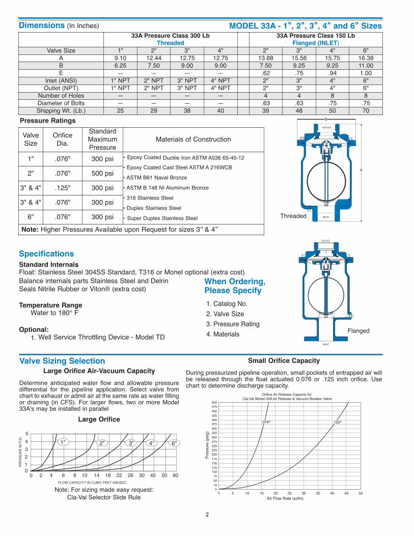
Large Orifice Air-Vacuum Capacity
Determine anticipated water flow and allowable pressuredifferential for the pipeline application. Select valve fromchart to exhaust or admit air at the same rate as water fillingor draining (in CFS). For larger flows, two or more Model33A's may be installed in parallel
Note: For sizing made easy request:Cla-Val Selector Slide Rule
Large Orifice
Small Orifice Capacity
During pressurized pipeline operation, small pockets of entrapped air willbe released through the float actuated 0.076 or .125 inch orifice. Usechart to determine discharge capacity.
When Ordering, Please Specify
1. Catalog No.2. Valve Size3. Pressure Rating4. Materials
Specifications
MODEL 33A - 1", 2", 3", 4" and 6" Sizes
Valve Sizing Selection
50 60
6"
0 2 4 6 8 10 14 18 22 26 30 40FLOW CAPACITY IN CUBIC FEET AIR/SEC.
PRES
SURE
IN P
.SI.
543210
1" 2" 4"3"
0 5 10 15 20 400
105075
100125150175200225250275300325350375400425450475500
25 30 35 45 50
Orifice Air Release Capacity for Cla-Val Model 33A Air Release & Vacuum Breaker Valve
Air Flow Rate (scfm)
Pres
sure
(psig
)
.076" .125"
Dimensions (In Inches)
B
A
OUTLET
INLET
INLET
OUTLET
Pressure Ratings
Valve Size
OrificeDia.
StandardMaximum Pressure
Materials of Construction
1" .076" 300 psi • Epoxy Coated Ductile Iron ASTM A536 65-45-12• Epoxy Coated Cast Steel ASTM A 216WCB
• ASTM B61 Naval Bronze
• ASTM B 148 NI Aluminum Bronze
• 316 Stainless Steel
• Duplex Stainless Steel
• Super Duplex Stainless Steel
2" .076" 500 psi
3" & 4" .125" 300 psi
3" & 4" .076" 300 psi
6" .076" 300 psi
Note: Higher Pressures Available upon Request for sizes 3’’ & 4’’
33A Pressure Class 300 Lb
Threaded
33A Pressure Class 150 Lb
Flanged (INLET)Valve Size 1" 2" 3" 4" 2" 3" 4" 6"
A 9.10 12.44 12.75 12.75 13.88 15.56 15.75 16.38B 6.25 7.50 9.00 9.00 7.50 9.25 9.25 11.00E — — — — .62 .75 .94 1.00
Inlet (ANSI) 1" NPT 2" NPT 3" NPT 4" NPT 2" 3" 4" 6"Outlet (NPT) 1" NPT 2" NPT 3" NPT 4" NPT 2" 3" 4" 6"
Number of Holes — — — — 4 4 8 8Diameter of Bolts — — — — .63 .63 .75 .75Shipping Wt. (Lb.) 25 29 38 40 39 48 50 70
Flanged
Threaded
2
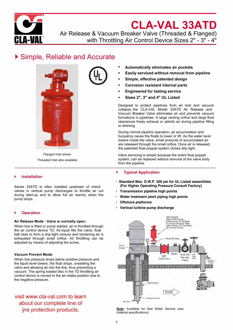
CLA-VAL 33ATDAir Release & Vacuum Breaker Valve (Threaded & Flanged)
with Throttling Air Control Device Sizes 2" - 3" - 4"
} Simple, Reliable and Accurate § Automatically eliminates air pockets§ Easily serviced without removal from pipeline§ Simple, effective patented design§ Corrosion resistant internal parts§ Engineered for lasting service
Designed to protect pipelines from air lock and vacuum collapse, the CLA-VAL Model 33ATD Air Release and Vacuum Breaker Valve eliminates air and prevents vacuum formations in pipelines. A large venting orifice and large float clearances freely exhaust or admits air during pipeline filling or draining.
During normal pipeline operation, air accumulation and buoyancy cause the floats to lower or lift. As the water level lowers inside the valve, small amounts of accumulated air are released through the small orifice. Once air is released, the patented float poppet system closes drip tight.
Valve servicing is simple because the entire float poppet system, can be replaced without removal of the valve body from the pipeline.
} Installation
Series 33ATD is often installed upstream of check valves in vertical pump discharges to throttle air out during start-up and to allow full air reentry when the pump stops.
} Operation
Air Release Mode - Valve is normally open:When line is filled or pump started, air is throttled throughthe air control device TD. As liquid fills the valve, float ball rises to form a drip-tight closure and remaining air is exhausted through small orifice. Air throttling can be adjusted by means of adjusting screw.
Vacuum Prevent Mode: When line pressure drops below positive pressure and the liquid level lowers, the float drops, unseating the valve and allowing air into the line, thus preventing a vacuum. The spring loaded disc in the TD throttling air control device is moved to the air intake position due to the negative pressure.
Note: Available for Sea Water Service (see material specifications).
} Typical Application
• psiPressure Consult Factory)
• Transmission pipeline high points• Water treatment plant piping high points• Offshore platforms• Vertical turbine pump discharge
Flanged
Threaded also available
§
visit www.cla-val.com to learn about our complete line ofÿre protection products.
Sizes 2", 3" and 4" UL Listed
3
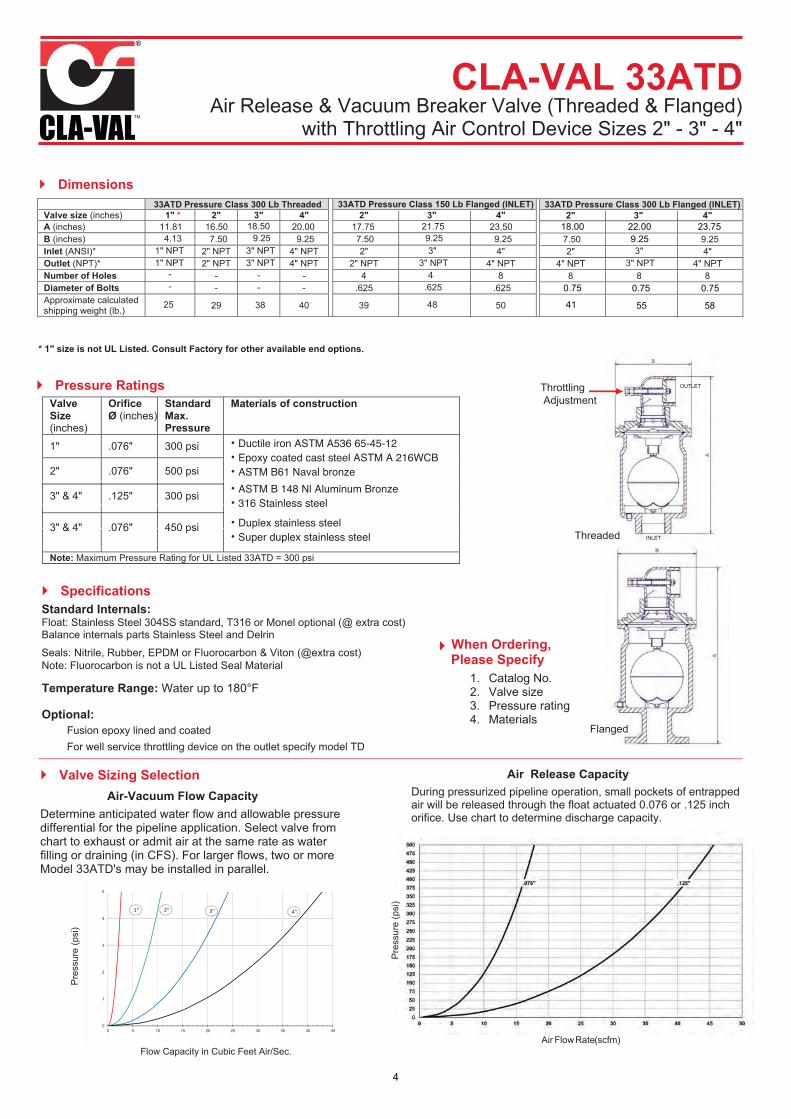
Dimensions
* 1" size is not UL Listed. Consult Factory for other available end options.
Pressure Ratings Valve Size(inches)
OrificeØ (inches)
StandardMax.Pressure
Materials of construction
1" .076" 300 psi
316
2" .076" 500 psi
3" & 4" .125" 300 psi
3" & 4" .076" psi
Note:
Specifications Standard Internals: Float: Stainless Steel 304SS standard, T316 or Monel optional ( extra cost)Balance internals parts Stainless Steel and Delrin
Seals Nitrile ( extra cost)
Temperature Range: Water up to 180°F
Optional: Fusion epoxy lined and coated For well service throttling device on the outlet specify model TD
Valve Sizing Selection Air-Vacuum Capacity
Determine anticipated water flow and allowable pressure differential for the pipeline application. Select valve from chart to exhaust or admit air at the same rate as water filling or draining (in CFS). For larger flows, two or more Model 33ATD's may be installed in parallel.
During pressurized pipeline operation, small pockets of entrapped air will be released through the float actuated 0.076 or .125 inch orifice. Use chart to determine discharge capacity.
When Ordering, Please Specify
1. Catalog No.2. Valve size3. Pressure rating4. Materials
Pre
ssur
e (p
si)
Threaded
OUTLET
INLET
OUTLET
INLET Flanged
Air Flow Rate (scfm)Flow Capacity in Cubic Feet Air/Sec.
Pre
ssur
e (p
si)
33ATD Pressure Class 300 Lb Threaded 33ATD Pressure Class 150 Lb Flanged (INLET) Valve size (inches) 1" * 2" 3" 4" 2" 3" 4" A ( ) 1B ( ) 5Inlet (ANSI)* 2" NPT 3" NPT 4" NPT 2" 4"Outlet (NPT)* 2" NPT 3" NPT 4" NPT 2" 4"Number of Holes - - - 4 8Diameter of Bolts - - - Approximate calculated shipping weight (
--
33ATD Pressure Class 300 Lb Flanged (INLET) 2" 3" 4"
2" 4"4" 4"
8 8 8
18.00 22.00 23.759.25
41 55 58
0.75 0.75 0.75
0
1
2
3
4
5
0 5 10 15 20 25 30 35 40 45
1" 2" 3" 4"
CLA-VAL 33ATDAir Release & Vacuum Breaker Valve (Threaded & Flanged)
with Throttling Air Control Device Sizes 2" - 3" - 4"
4
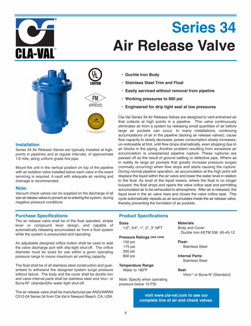
Air Release Valve
Series 34
• Ductile Iron Body
• Stainless Steel Trim and Float
• Easily serviced without removal from pipeline
• Working pressures to 800 psi
• Engineered for drip tight seal at low pressures
Cla-Val Series 34 Air Release Valves are designed to vent entrained airthat collects at high points in a pipeline. This valve continuouslyeliminates air from a system by releasing small quantities of air beforelarge air pockets can occur. In many installations, continuingaccumulations of air in the pipeline (lacking air release valves); causeflow capacity to slowly decrease; power consumption slowly increases;un-noticeable at first, until flow drops dramatically, even stopping due toair blocks in the piping. Another problem resulting from excessive airaccumulation is unexplained pipeline rupture. These ruptures arepassed off as the result of ground settling or defective pipe, Where asin reality its large air pockets that greatly increase pressure surges(normally occurring) when flow stops and starts causing the rupture.During normal pipeline operation, air accumulation at the high point willdisplace the liquid within the air valve and lower the water level in relationto the float. As level of the liquid lowers, where the float is no longerbuoyant, the float drops and opens the valve orifice seat and permittingaccumulated air to be exhausted to atmosphere. After air is released, theliquid level in the air valve rises and closes the valve orifice seat. Thiscycle automatically repeats as air accumulates inside the air release valve,thereby preventing the formation of air pockets.
This product meets Federal Mandate for Lead Content Limit
InstallationSeries 34 Air Release Valves are typically installed at high-points in pipelines and at regular intervals, of approximate1/2 mile, along uniform grade line pipe.
Mount the unit in the vertical position on top of the pipelinewith an isolation valve installed below each valve in the eventservicing is required. A vault with adequate air venting anddrainage is recommended.
Purchase SpecificationsThe air release valve shall be of the float operated, simplelever or compound lever design, and capable ofautomatically releasing accumulated air from a fluid systemwhile the system is pressurized and operating.
An adjustable designed orifice button shall be used to sealthe valve discharge port with drip-tight shut-off. The orificediameter must be sized for use within a given operatingpressure range to insure maximum air venting capacity.
The float shall be of all stainless steel construction and guar-anteed to withstand the designed system surge pressurewithout failure. The body and the cover shall be ductile ironand valve internal parts shall be stainless steel and VitonTM orBuna-N® (standard)for water tight shut-off.
The air release valve shall be manufactured per ANSI/AWWAC512-04 Series 34 from Cla-Val in Newport Beach, CA, USA.
Product Specifications
Sizes
1/2", 3/4", 1", 2", 3" NPT
Pressure Ratings (see note)
150 psi175 psi
300 psi 800 psi
Temperature Range
Water to 180°F
Note: Specify when operating pressure below 10 PSI
Materials
Body and Cover:Ductile Iron ASTM 536 65-45-12
Float:
Stainless Steel
Internal Parts:
Stainless Steel
Seal:
VitonTM or Buna-N® (Standard)
Note:Vacuum check valves can be supplied on the discharge of allsize air release valves to prevent air re-entering the system; duringnegative pressure conditions
visit www.cla-val.com to see our
complete line of air and check valves.
5
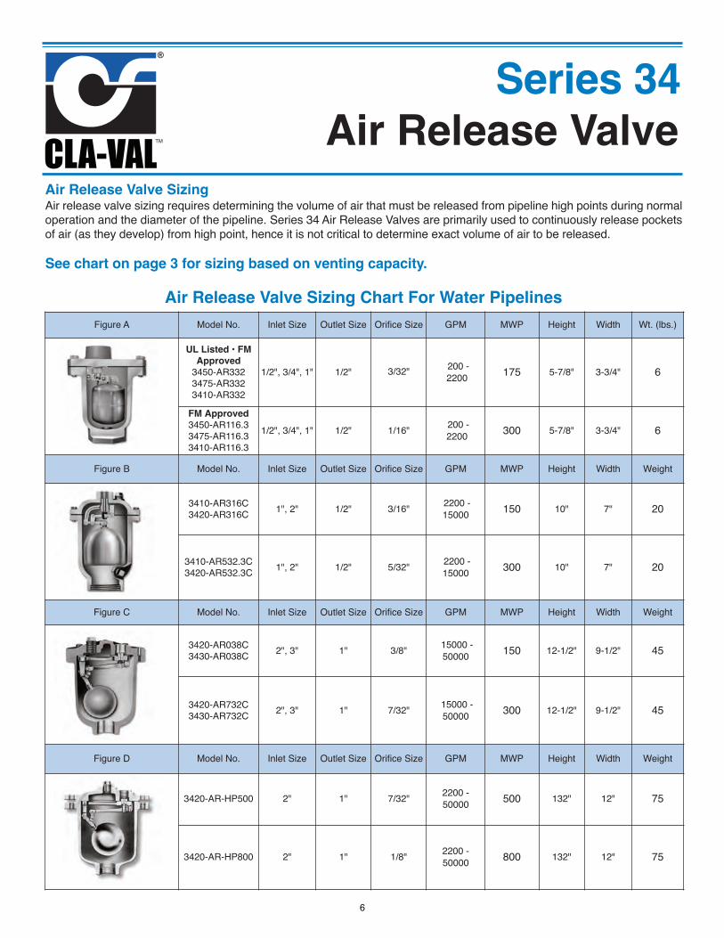
Series 34Air Release Valve
Air Release Valve Sizing Air release valve sizing requires determining the volume of air that must be released from pipeline high points during normaloperation and the diameter of the pipeline. Series 34 Air Release Valves are primarily used to continuously release pocketsof air (as they develop) from high point, hence it is not critical to determine exact volume of air to be released.
See chart on page 3 for sizing based on venting capacity.
Figure A Model No. Inlet Size Outlet Size Orifice Size GPM MWP Height Width Wt. (lbs.)
UL Listed • FMApproved
3450-AR3323475-AR3323410-AR332
1/2", 3/4", 1" 1/2" 3/32" 200 -2200 175 5-7/8" 3-3/4" 6
FM Approved3450-AR116.33475-AR116.33410-AR116.3
1/2", 3/4", 1" 1/2" 1/16" 200 -2200 300 5-7/8" 3-3/4" 6
Figure B Model No. Inlet Size Outlet Size Orifice Size GPM MWP Height Width Weight
3410-AR316C3420-AR316C 1", 2" 1/2" 3/16" 2200 -
15000 150 10" 7" 20
3410-AR532.3C3420-AR532.3C 1", 2" 1/2" 5/32" 2200 -
15000 300 10" 7" 20
Figure C Model No. Inlet Size Outlet Size Orifice Size GPM MWP Height Width Weight
3420-AR038C3430-AR038C 2", 3" 1" 3/8" 15000 -
50000 150 12-1/2" 9-1/2" 45
3420-AR732C3430-AR732C 2", 3" 1" 7/32" 15000 -
50000 300 12-1/2" 9-1/2" 45
Figure D Model No. Inlet Size Outlet Size Orifice Size GPM MWP Height Width Weight
3420-AR-HP500 2" 1" 7/32" 2200 -50000 500 132" 12" 75
3420-AR-HP800 2" 1" 1/8" 2200 -50000 800 132" 12" 75
Air Release Valve Sizing Chart For Water Pipelines
6
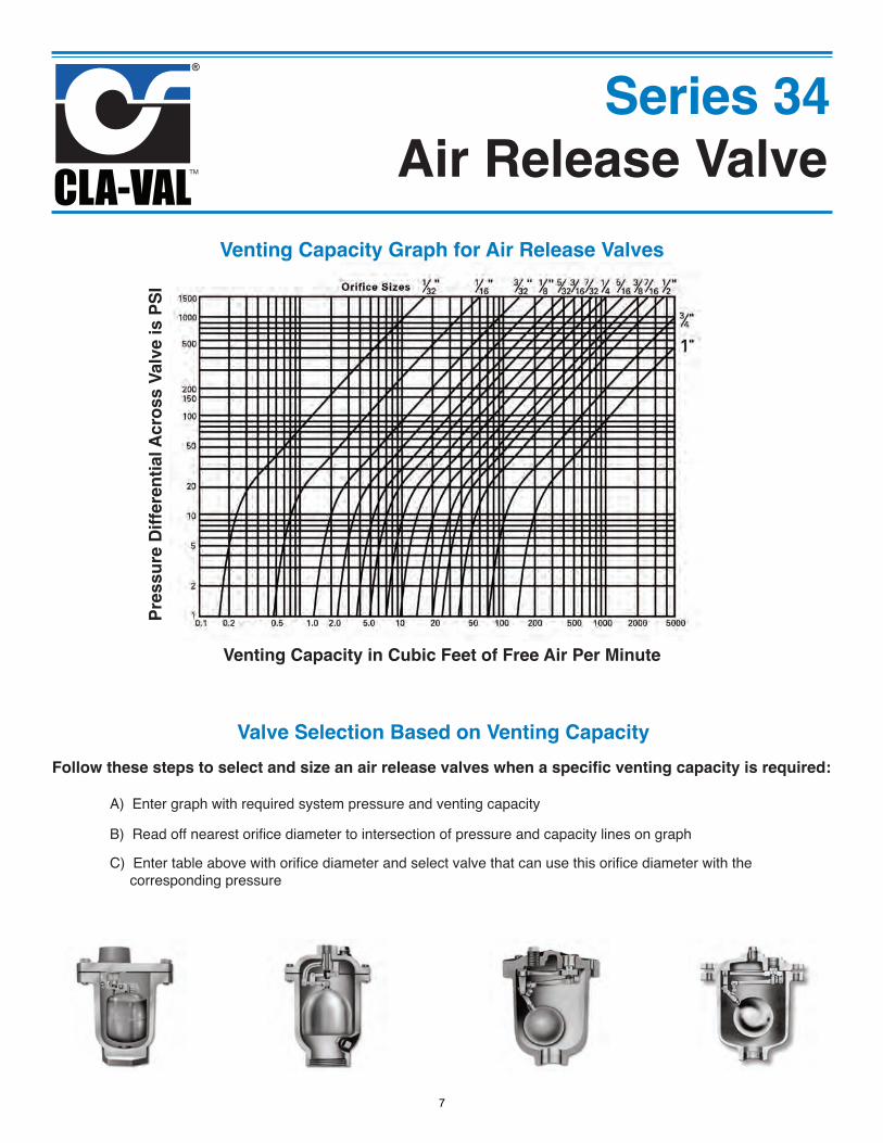
Series 34Air Release Valve
Venting Capacity Graph for Air Release Valves
Venting Capacity in Cubic Feet of Free Air Per Minute
Pres
sure
Diff
eren
tial A
cros
s Va
lve
is P
SI
Valve Selection Based on Venting CapacityFollow these steps to select and size an air release valves when a specific venting capacity is required:
A) Enter graph with required system pressure and venting capacity
B) Read off nearest orifice diameter to intersection of pressure and capacity lines on graphC) Enter table above with orifice diameter and select valve that can use this orifice diameter with the
corresponding pressure
7
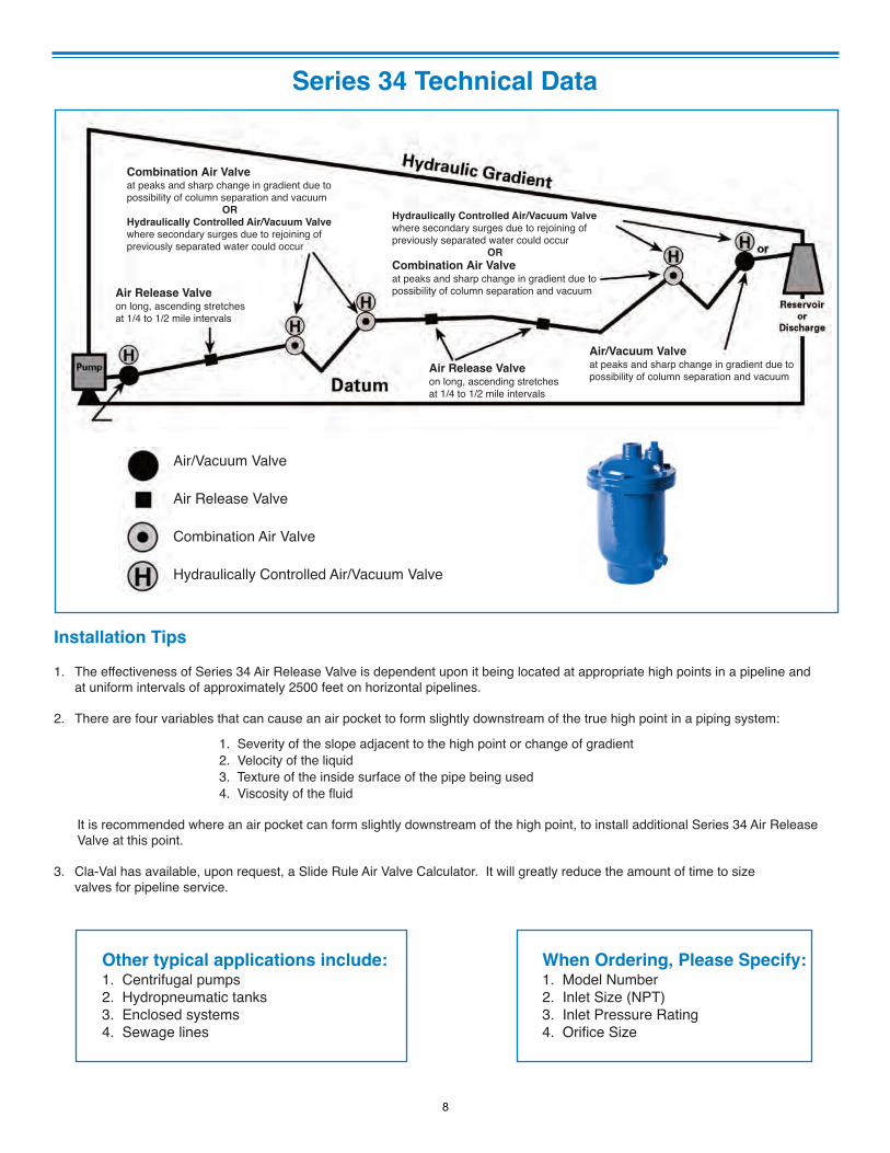
Series 34 Technical Data
When Ordering, Please Specify:1. Model Number2. Inlet Size (NPT)3. Inlet Pressure Rating4. Orifice Size
Installation Tips
1. The effectiveness of Series 34 Air Release Valve is dependent upon it being located at appropriate high points in a pipeline andat uniform intervals of approximately 2500 feet on horizontal pipelines.
2. There are four variables that can cause an air pocket to form slightly downstream of the true high point in a piping system:
1. Severity of the slope adjacent to the high point or change of gradient2. Velocity of the liquid3. Texture of the inside surface of the pipe being used4. Viscosity of the fluid
It is recommended where an air pocket can form slightly downstream of the high point, to install additional Series 34 Air Release Valve at this point.
3. Cla-Val has available, upon request, a Slide Rule Air Valve Calculator. It will greatly reduce the amount of time to sizevalves for pipeline service.
Other typical applications include:1. Centrifugal pumps2. Hydropneumatic tanks3. Enclosed systems4. Sewage lines
Combination Air Valveat peaks and sharp change in gradient due topossibility of column separation and vacuum
OR
Hydraulically Controlled Air/Vacuum Valve
where secondary surges due to rejoining ofpreviously separated water could occur
Air Release Valveon long, ascending stretchesat 1/4 to 1/2 mile intervals
Hydraulically Controlled Air/Vacuum Valve
where secondary surges due to rejoining ofpreviously separated water could occur
OR
Combination Air Valveat peaks and sharp change in gradient due topossibility of column separation and vacuum
Air Release Valveon long, ascending stretchesat 1/4 to 1/2 mile intervals
Air/Vacuum Valveat peaks and sharp change in gradient due topossibility of column separation and vacuum
Air/Vacuum Valve
Air Release Valve
Combination Air Valve
Hydraulically Controlled Air/Vacuum Valve
8
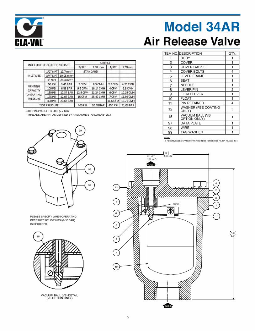
INLET
OUTLET
ORIFICE
NOTE:
ITEM NO. DESCRIPTION QTY.
Model 34ARAir Release Valve
123456789
101112
15979899
12
5
6
8
9
10
11
15
97
98
99
7
2
3
4
1
9
VACUUM BALL (VB) DETAIL
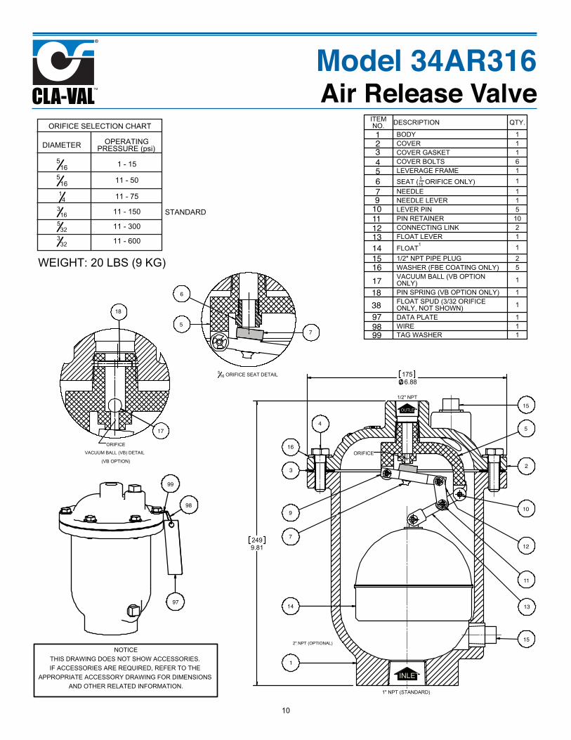
ITEM NO. DESCRIPTION QTY.
INLET
OUTLET
Model 34AR316Air Release Valve
12345679
10111213141516171838979899
1
23
45
6
7
9 10
11
12
1314
15
16
17
18
97
98
99
15
75
ORIFICE SELECTION CHART
DIAMETER OPERATING PRESSURE (psi)
10
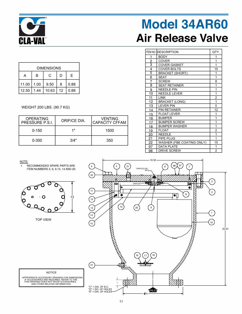
ITEM NO. DESCRIPTION QTY.
OPERATING PRESSURE P.S.I. ORIFICE DIA. VENTING
CAPACITY CFFAM
DIMENSIONS
A B C D E
INLET
OUTLET
NOTE:
Model 34AR60Air Release Valve
1234567
9101112131415161718
9798
4
8
19202122
1
2
3
5
6 7
910
11
12
13
14
15
16 17 18
9798
8
19
20
21
22
211. RECOMMENDED SPARE PARTS ARE ITEM NUMBERS 3, 6, 9,13, 14 AND 20.
11
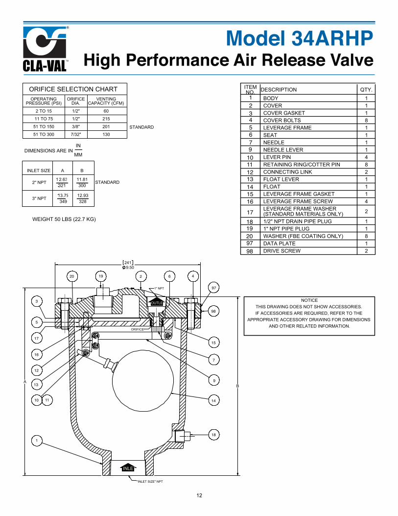
ORIFICE SELECTION CHARTOPERATING
PRESSURE (PSI)ORIFICE
DIA.VENTING
CAPACITY (CFM)
INLET SIZE A B
2" NPT
3" NPT
ITEM NO. DESCRIPTION QTY.
INLET
OUTLET
WEIGHT 50 LBS (22.7 KG)
Model 34ARHPHigh Performance Air Release Valve
12345679
101112131415161718
9798
1920
1
2
3
4
5
6
7
9
10 11
12
13
14
15
16
17
18
97
98
1920
12
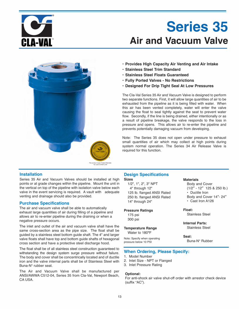
• Provides High Capacity Air Venting and Air Intake
• Stainless Steel Trim Standard
• Stainless Steel Floats Guaranteed
• Fully Ported Valves - No Restrictions
• Designed For Drip Tight Seal At Low Pressures
The Cla-Val Series 35 Air and Vacuum Valve is designed to performtwo separate functions. First, it will allow large quantities of air to beexhausted from the pipeline as it is being filled with water. Whenthis air has been vented completely, water will enter the valvecausing the float to seal tightly against the seat to prevent waterflow. Secondly, if the line is being drained, either intentionally or asa result of pipeline breakage, the valve responds to the loss inpressure and opens. This allows air to re-enter the pipeline andprevents potentially damaging vacuum from developing.
Note: The Series 35 does not open under pressure to exhaustsmall quantities of air which may collect at high points duringsystem normal operation. The Series 34 Air Release Valve isrequired for this function.
Design SpecificationsSizes
1/2", 1", 2", 3" NPT 4" through 12" 125 lb. flanged ANSI Rated 250 lb. flanged ANSI Rated 14" through 24"
Pressure Ratings
175 psi 300 psi
Temperature Range
Water to 180°FNote: Specify when operating pressure below 10 PSI
Materials
Body and Cover (1/2” - 12” 125 & 250 lb.)• Ductile IronBody and Cover 14”- 24” • Cast Iron A126
Float:
Stainless Steel
Internal Parts:
Stainless Steel
Seal:
Buna-N® Rubber
InstallationSeries 35 Air and Vacuum Valves should be installed at highpoints or at grade changes within the pipeline. Mount the unit inthe vertical on top of the pipeline with isolation valve below eachvalve in the event servicing is required. A vault with adequateventing and drainage should also be provided.
Purchase SpecificationsThe air and vacuum valve shall be able to automaticallyexhaust large quantities of air during filling of a pipeline andallows air to re-enter pipeline during the draining or when anegative pressure occurs.The inlet and outlet of the air and vacuum valve shall have thesame cross-section area as the pipe size. The float shall beguided by a stainless steel bottom guide shaft. The 4" and largervalve floats shall have top and bottom guide shafts of hexagonalcross section and have a protective steel discharge hood.The float shall be of all stainless steel construction guaranteed towithstanding the design system surge pressure without failure.The body and cover shall be concentrically located and of ductileiron and the valve internal parts shall be of Stainless Steel withBuna-N® rubber seat. The Air and Vacuum Valve shall be manufactured perANSI/AWWA C512-04, Series 35 from Cla-Val, Newport Beach,CA USA.
When Ordering, Please Specify:1. Model Number2. Inlet Size - NPT or Flanged3. Inlet Pressure Rating
Optional:
For anti-shock air valve shut-off order with arrestor check device(suffix “AC”).
This product meets Federal Mandate for Lead Content Limit
13
Air and Vacuum ValveSeries 35
Air and Vacuum Valve
INLET
14A
B
2
8
4
7
6
3
5
20
9
1
14
14A
B
TEST PRESSURE1.5 TIMES
WORKING PRESSURE
OPTIONAL FLANGE125 OR 250 CLASS
INLET
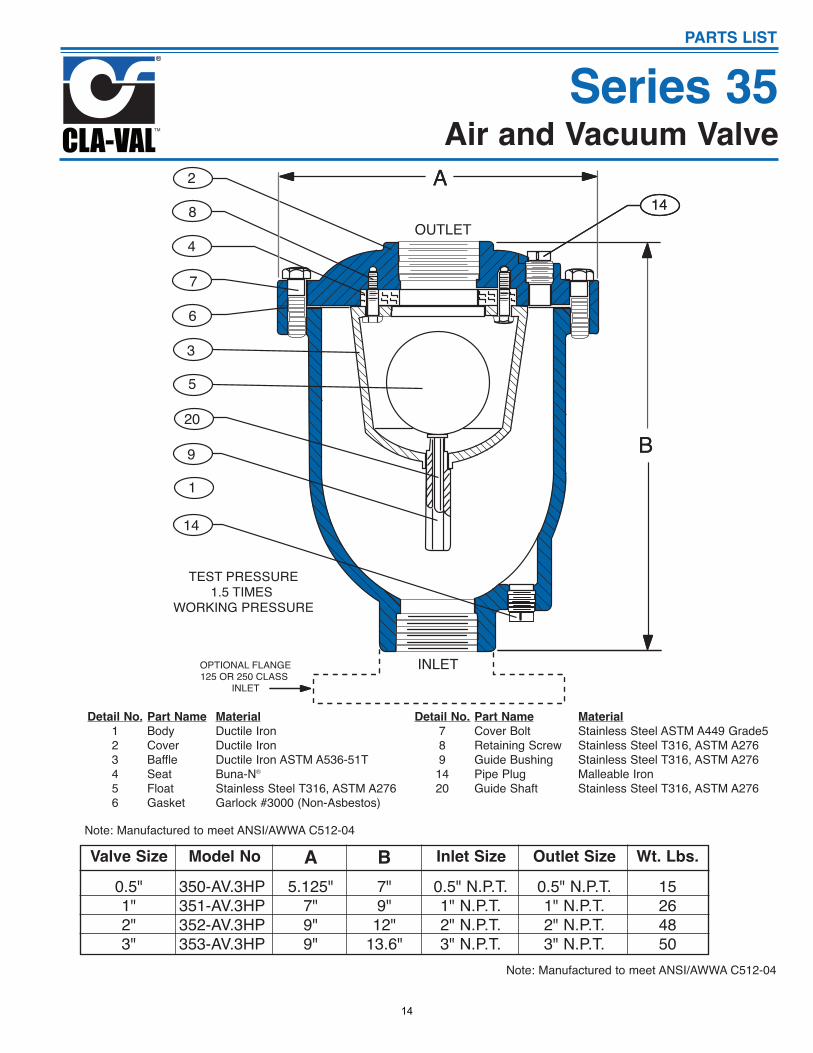
Series 35PARTS LIST
Detail No.123456
Part NameBodyCoverBaffleSeatFloatGasket
MaterialDuctile IronDuctile IronDuctile Iron ASTM A536-51TBuna-N®
Stainless Steel T316, ASTM A276Garlock #3000 (Non-Asbestos)
Detail No.789
1420
Part NameCover BoltRetaining ScrewGuide BushingPipe PlugGuide Shaft
MaterialStainless Steel ASTM A449 Grade5 Stainless Steel T316, ASTM A276Stainless Steel T316, ASTM A276Malleable IronStainless Steel T316, ASTM A276
Valve Size Model No A B Inlet Size Outlet Size
0.5"1"2"3"
350-AV.3HP351-AV.3HP352-AV.3HP353-AV.3HP
5.125"7"9"9"
7"9"12"
13.6"
0.5" N.P.T.1" N.P.T.2" N.P.T.3" N.P.T.
0.5" N.P.T.1" N.P.T.2" N.P.T.3" N.P.T.
Wt. Lbs.
15264850
Note: Manufactured to meet ANSI/AWWA C512-04
Note: Manufactured to meet ANSI/AWWA C512-04
14
Model 35AV - 1/2” - 3”Air Release / Vacuum Valve
INLET
OUTLET
(NOTE 2)
3" 146 DETAIL
1/2" - 1" DATA PLATE DETAIL
WATER DIFFUSER OPTION DETAIL(WD ORDER CODE)
2" - 3" DATA PLATE DETAIL
OPTIONAL NIPPLE & FLANGEINLET (F1N OR F2N)
OPTIONAL FLANGED OUTLET(FL)
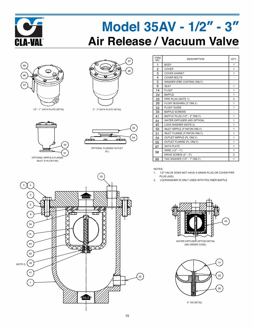
NOTES:1/2" VALVE DOES NOT HAVE A DRAIN PLUG OR COVER PIPE 1.PLUG (A25).LOCKWASHER IS ONLY USED WITH POLYMER BAFFLE2.
ITEM NO. DESCRIPTION QTY.
BODY 1
COVER 1
COVER GASKET 1
COVER BOLTS -
WASHER (FBE COATING ONLY) -
SEAT 1
FLOAT 1
BAFFLE 1
PIPE PLUG (NOTE 1) 2
FLOAT BUSHING (3" ONLY) 1
FLOAT GUIDE 1
BAFFLE SCREWS -
BAFFLE PLUG (1/2" - 2" ONLY) 1
WATER DIFFUSER (WD OPTION) 1
LOCK WASHER (NOTE 2) 1
INLET NIPPLE (F1N/F2N ONLY) 1
INLET FLANGE (F1N/F2N ONLY) 1
OUTLET NIPPLE (FL ONLY) 1
OUTLET FLANGE (FL ONLY) 1
DATA PLATE 1
WIRE (1/2" - 1") 1
DRIVE SCREW (2" - 3") 2
TAG WASHER (1/2" - 1" ONLY) 1
123456
2414
9798
33
99
2526
3441444550515455
1
2
3
45
6
24
14
97
98
33
99
25
26
34
41
1445
50
51
54
55
97
98
25 33
44
15
Model 35AVAir Release / Vacuum Valve
DC
E
B
A
X
SEE DETAIL B& NOTE 2
OUTLET
INLET
1
2
3
6
16
40
28
29
26
43
"F" = DIA. OF B.C."G" = No. OF HOLES"H" = DIA. OF HOLES
44
4
VALVES WITH CORROSION RESISTANT BODY/COVER HAVE A STEEL HOOD COATED WITH A FUSION BONDED EPOXY AS A STANDARD.
14
(4)
HSB, HSR - BUG & ROCK SCREEN OPTION
58
2
DETAIL A(SEAT DETAIL)
(NOTE 1)
6
14
(NOTE 1)
16(NOTE 3)
TH - THREADED OUTLET OPTION (4" - 8")
2
FL - FLANGED OUTLET OPTION(CONSULT FACTORY FOR INSTALLATION DIMENSIONS)
2
DETAIL B(COVER SEAL DETAIL)
(NOTE 2)
3
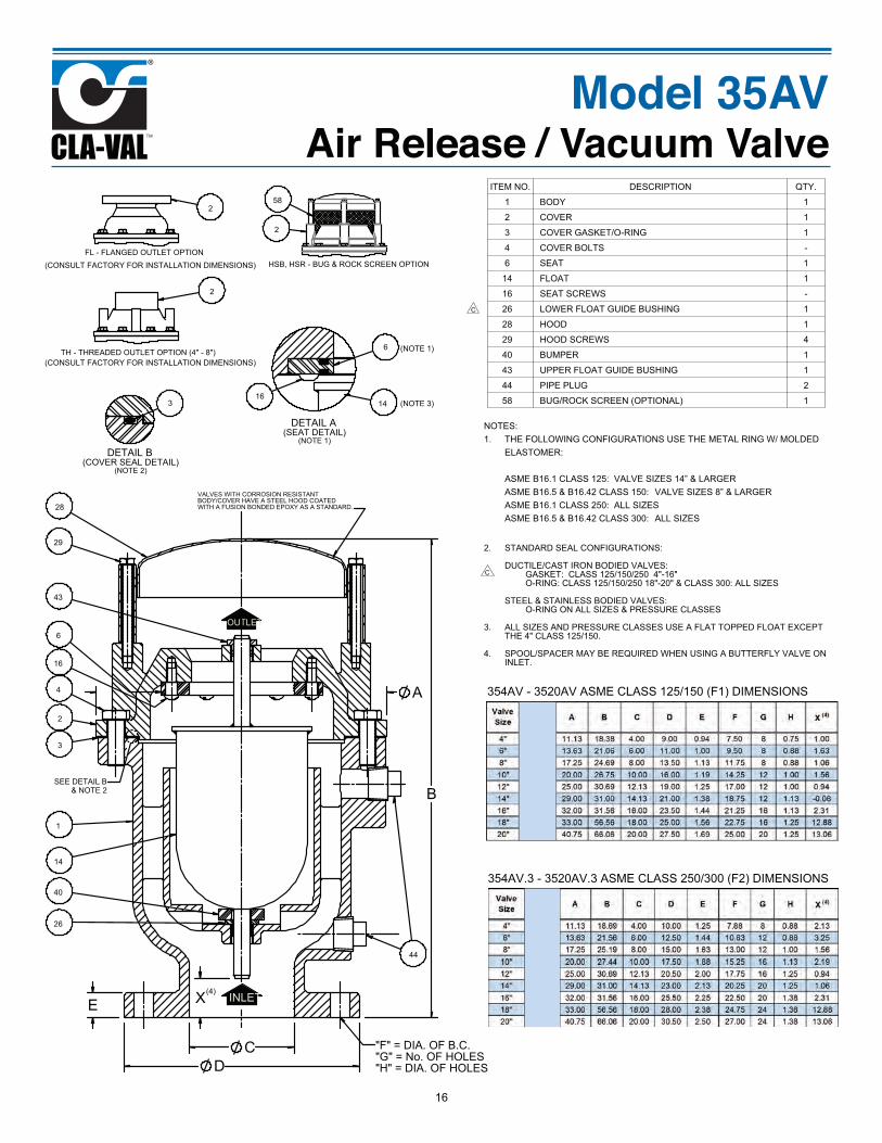
354AV - 3520AV ASME CLASS 125/150 (F1) DIMENSIONS
354AV.3 - 3520AV.3 ASME CLASS 250/300 (F2) DIMENSIONS
NOTES:THE FOLLOWING CONFIGURATIONS USE THE METAL RING W/ MOLDED 1.ELASTOMER:
ASME B16.1 CLASS 125: VALVE SIZES 14” & LARGERASME B16.5 & B16.42 CLASS 150: VALVE SIZES 8” & LARGERASME B16.1 CLASS 250: ALL SIZESASME B16.5 & B16.42 CLASS 300: ALL SIZES
STANDARD SEAL CONFIGURATIONS:2.
DUCTILE/CAST IRON BODIED VALVES:GASKET: CLASS 125/150/250 4"-16"O-RING: CLASS 125/150/250 18"-20" & CLASS 300: ALL SIZES
STEEL & STAINLESS BODIED VALVES:O-RING ON ALL SIZES & PRESSURE CLASSES
ALL SIZES AND PRESSURE CLASSES USE A FLAT TOPPED FLOAT EXCEPT 3.THE 4" CLASS 125/150.
SPOOL/SPACER MAY BE REQUIRED WHEN USING A BUTTERFLY VALVE ON 4.INLET.
C
C
ITEM NO. DESCRIPTION QTY.
1 BODY 1
2 COVER 1
3 COVER GASKET/O-RING 1
4 COVER BOLTS -
6 SEAT 1
14 FLOAT 1
16 SEAT SCREWS -
26 LOWER FLOAT GUIDE BUSHING 1
28 HOOD 1
29 HOOD SCREWS 4
40 BUMPER 1
43 UPPER FLOAT GUIDE BUSHING 1
44 PIPE PLUG 2
58 BUG/ROCK SCREEN (OPTIONAL) 1
(CONSULT FACTORY FOR INSTALLATION DIMENSIONS)
16
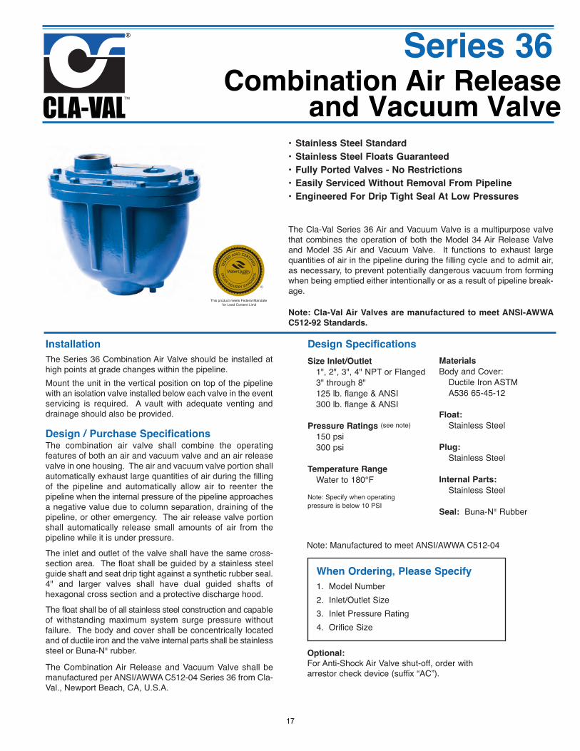
Design / Purchase SpecificationsThe combination air valve shall combine the operatingfeatures of both an air and vacuum valve and an air releasevalve in one housing. The air and vacuum valve portion shallautomatically exhaust large quantities of air during the fillingof the pipeline and automatically allow air to reenter thepipeline when the internal pressure of the pipeline approachesa negative value due to column separation, draining of thepipeline, or other emergency. The air release valve portionshall automatically release small amounts of air from thepipeline while it is under pressure.
The inlet and outlet of the valve shall have the same cross-section area. The float shall be guided by a stainless steelguide shaft and seat drip tight against a synthetic rubber seal.4" and larger valves shall have dual guided shafts ofhexagonal cross section and a protective discharge hood.
The float shall be of all stainless steel construction and capableof withstanding maximum system surge pressure withoutfailure. The body and cover shall be concentrically locatedand of ductile iron and the valve internal parts shall be stainlesssteel or Buna-N® rubber.
The Combination Air Release and Vacuum Valve shall bemanufactured per ANSI/AWWA C512-04 Series 36 from Cla-Val., Newport Beach, CA, U.S.A.
Combination Air Releaseand Vacuum Valve
Installation
The Series 36 Combination Air Valve should be installed athigh points at grade changes within the pipeline. Mount the unit in the vertical position on top of the pipelinewith an isolation valve installed below each valve in the eventservicing is required. A vault with adequate venting anddrainage should also be provided.
Design Specifications
Size Inlet/Outlet
1", 2", 3", 4" NPT or Flanged 3" through 8" 125 lb. flange & ANSI 300 lb. flange & ANSI
Pressure Ratings (see note)
150 psi 300 psi
Temperature Range
Water to 180°F
Note: Specify when operating pressure is below 10 PSI
Materials
Body and Cover: Ductile Iron ASTM A536 65-45-12
Float:
Stainless Steel
Plug:
Stainless Steel
Internal Parts:
Stainless Steel
Seal: Buna-N® Rubber
When Ordering, Please Specify
1. Model Number2. Inlet/Outlet Size3. Inlet Pressure Rating4. Orifice Size
Optional:
For Anti-Shock Air Valve shut-off, order witharrestor check device (suffix “AC”).
Series 36
Note: Manufactured to meet ANSI/AWWA C512-04
This product meets Federal Mandate for Lead Content Limit
• Stainless Steel Standard
• Stainless Steel Floats Guaranteed
• Fully Ported Valves - No Restrictions
• Easily Serviced Without Removal From Pipeline
• Engineered For Drip Tight Seal At Low Pressures
The Cla-Val Series 36 Air and Vacuum Valve is a multipurpose valvethat combines the operation of both the Model 34 Air Release Valveand Model 35 Air and Vacuum Valve. It functions to exhaust largequantities of air in the pipeline during the filling cycle and to admit air,as necessary, to prevent potentially dangerous vacuum from formingwhen being emptied either intentionally or as a result of pipeline break-age.
Note: Cla-Val Air Valves are manufactured to meet ANSI-AWWA
C512-92 Standards.
17
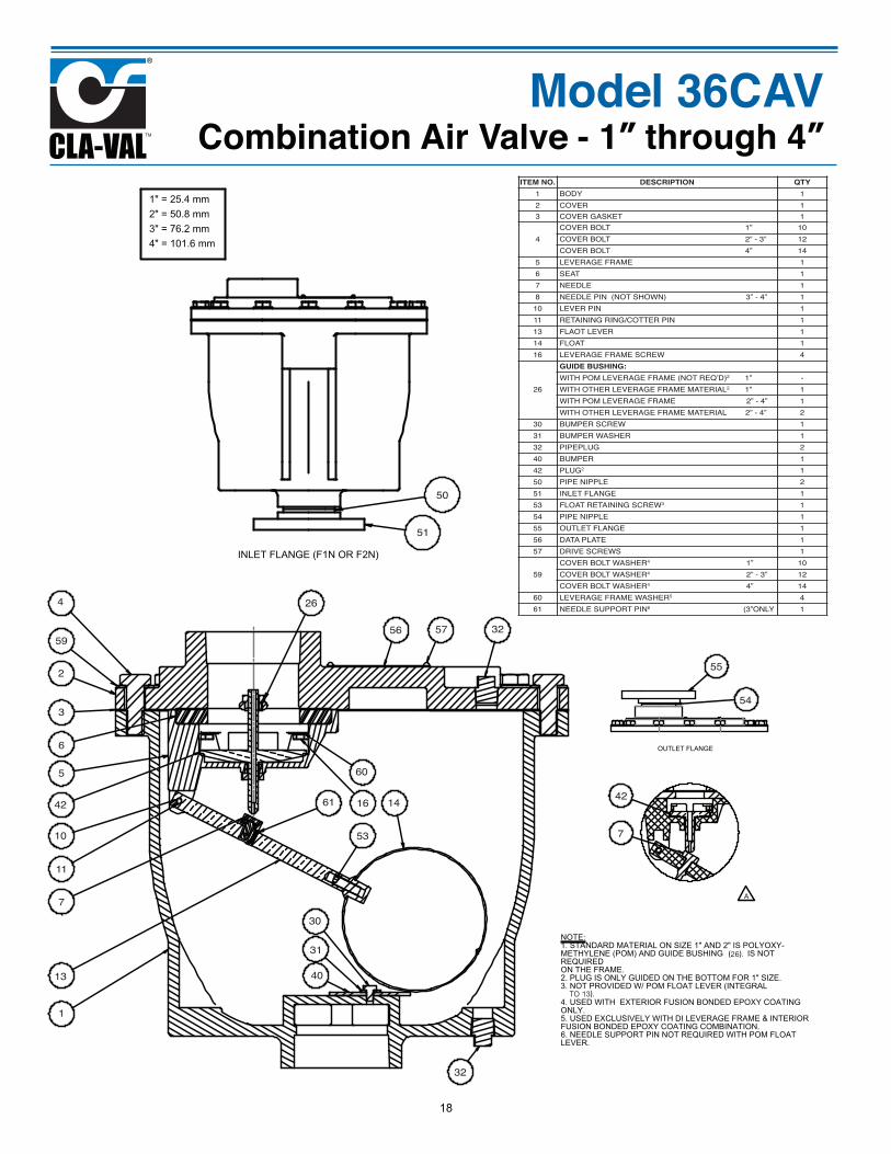
Model 36CAVCombination Air Valve - 1” through 4”
NOTE:
ITEM NO. DESCRIPTION QTY1 BODY 12 COVER 13 COVER GASKET 1
4COVER BOLT 1” 10COVER BOLT 2” - 3” 12COVER BOLT 4” 14
5 LEVERAGE FRAME 16 SEAT 17 NEEDLE 18 NEEDLE PIN (NOT SHOWN) 3” - 4” 110 LEVER PIN 111 RETAINING RING/COTTER PIN 113 FLAOT LEVER 114 FLOAT 116 LEVERAGE FRAME SCREW 4
26
GUIDE BUSHING:WITH POM LEVERAGE FRAME (NOT REQ’D)2 1” -WITH OTHER LEVERAGE FRAME MATERIAL2 1” 1WITH POM LEVERAGE FRAME 2” - 4” 1WITH OTHER LEVERAGE FRAME MATERIAL 2” - 4” 2
30 BUMPER SCREW 131 BUMPER WASHER 132 PIPEPLUG 240 BUMPER 142 PLUG2 150 PIPE NIPPLE 251 INLET FLANGE 153 FLOAT RETAINING SCREW3 154 PIPE NIPPLE 155 OUTLET FLANGE 156 DATA PLATE 157 DRIVE SCREWS 1
59COVER BOLT WASHER4 1” 10COVER BOLT WASHER4 2” - 3” 12COVER BOLT WASHER4 4” 14
60 LEVERAGE FRAME WASHER5 461 NEEDLE SUPPORT PIN6 (3”ONLY 1
1
3
5
6
7
10
11
13
1416
26
30
31
32
40
42
50
51
53
54
55
56 5759
60
61
4
2
32
7
42
TO 13).
(26).
18
E
C "D" NPT
A
B
F
G
H
N
KBOLT CIRCLE
"L" OF HOLES"M" QTY OF HOLES PER FLANGE
J
ISOMETRIC VIEW
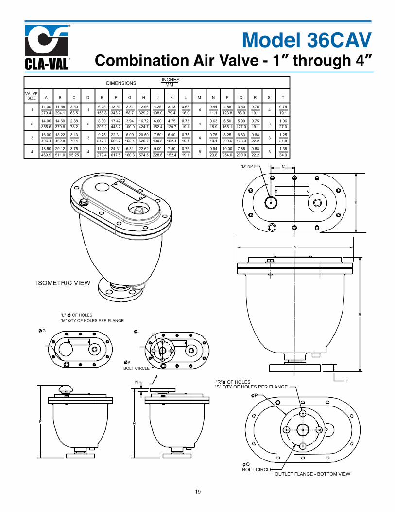
DIMENSIONS INCHES
MM
VALVESIZE A B C D E F G H J K L M N P Q R S T
111.00279.4
11.58294.1
2.5063.5
16.25
158.813.53343.7
2.3158.7
12.96329.2
4.25108.0
3.1379.4
0.6316.0
40.4411.1
4.88123.8
3.5088.9
0.7519.1
40.7519.1
214.00355.6
14.60370.8
2.8873.2
28.00
203.217.47443.7
3.94100.0
16.72424.7
6.00152.4
4.75120.7
0.7519.1
40.6315.9
6.50165.1
5.00127.0
0.7519.1
81.0627.0
316.00406.4
18.22462.8
3.1379.4
39.75
247.722.31566.7
6.00152.4
20.50520.7
7.50190.5
6.00152.4
0.7519.1
40.7519.1
8.25209.6
6.63168.3
0.8822.2
81.2531.8
418.50469.9
20.12511.0
3.7595.25
411.00279.4
24.31617.5
6.31160.3
22.62574.5
9.00228.6
7.50152.4
0.7519.1
80.9423.8
10.00254.0
7.88200.0
0.8822.2
81.3834.9
Model 36CAVCombination Air Valve - 1” through 4”
OUTLET FLANGE - BOTTOM VIEW
P
QBOLT CIRCLE
"R" OF HOLES"S" QTY OF HOLES PER FLANGE
T
19
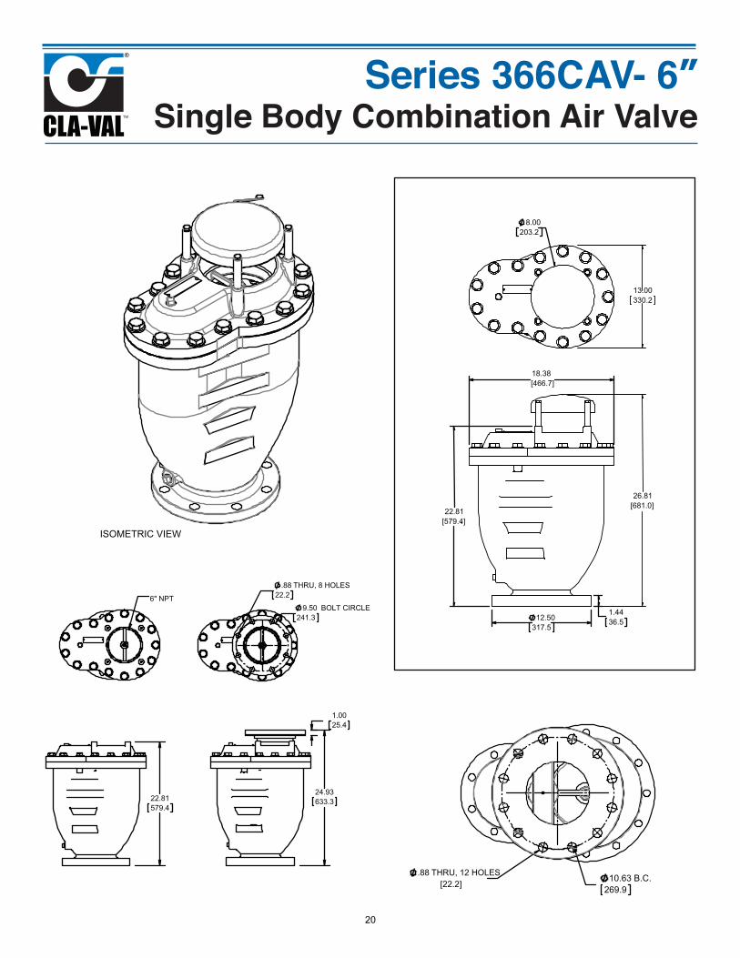
Series 366CAV- 6”Single Body Combination Air Valve
18.38[466.7]
1.4436.512.50
317.5
22.81[579.4]
26.81[681.0]
8.00203.2
13.00330.2
10.63269.9
B.C..88 THRU, 12 HOLES
ISOMETRIC VIEW
24.93633.3
1.0025.4
.8822.2
THRU, 8 HOLES
9.50241.3
BOLT CIRCLE
22.81579.4
6" NPT
[22.2]
20
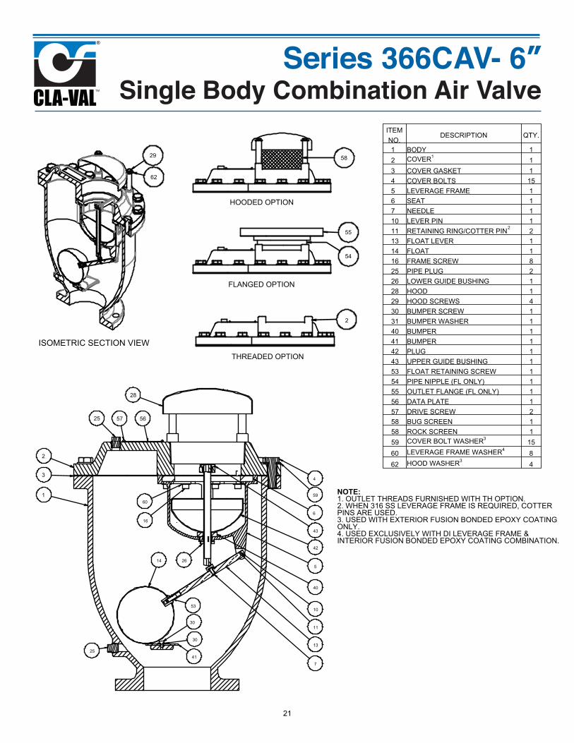
Series 366CAV- 6”Single Body Combination Air Valve
28
43
34
42
40
10
11
26
7
1
30
14
13
5
16
2
25
53
30
2541
57 56
6
6059
ISOMETRIC SECTION VIEW
29
62
HOODED OPTION
58
FLANGED OPTION
55
54
THREADED OPTION
2
2
ITEM NO.
DESCRIPTION QTY.
1 BODY 12 COVER1
13 COVER GASKET 14 COVER BOLTS 155 LEVERAGE FRAME 16 SEAT 17 NEEDLE 110 LEVER PIN 111 RETAINING RING/COTTER PIN 213 FLOAT LEVER 114 FLOAT 116 FRAME SCREW 825 PIPE PLUG 226 LOWER GUIDE BUSHING 128 HOOD 129 HOOD SCREWS 430 BUMPER SCREW 131 BUMPER WASHER 140 BUMPER 141 BUMPER 142 PLUG 143 UPPER GUIDE BUSHING 153 FLOAT RETAINING SCREW 154 PIPE NIPPLE (FL ONLY) 155 OUTLET FLANGE (FL ONLY) 156 DATA PLATE 157 DRIVE SCREW 258 BUG SCREEN 158 ROCK SCREEN 159 COVER BOLT WASHER3
1560 LEVERAGE FRAME WASHER4
862 HOOD WASHER3
4
NOTE:1. OUTLET THREADS FURNISHED WITH TH OPTION.2. WHEN 316 SS LEVERAGE FRAME IS REQUIRED, COTTERPINS ARE USED.3. USED WITH EXTERIOR FUSION BONDED EPOXY COATINGONLY.4. USED EXCLUSIVELY WITH DI LEVERAGE FRAME &INTERIOR FUSION BONDED EPOXY COATING COMBINATION.
21
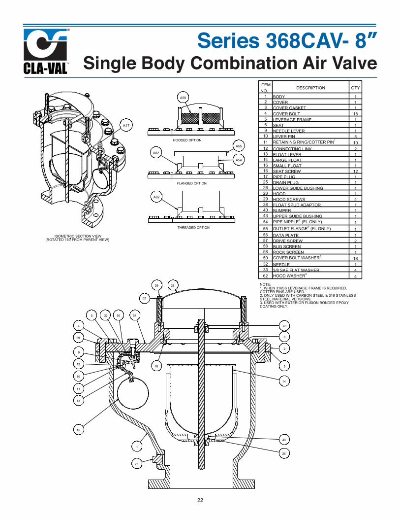
Series 368CAV- 8”Single Body Combination Air Valve
29
16
6
2
28
434
3
14
40
1
25
15
13
11
10
12
5
9
32
26
56 57
59
NOTE:1. WHEN 316SS LEVERAGE FRAME IS REQUIRED, COTTER PINS ARE USED.2. ONLY USED WITH CARBON STEEL & 316 STAINLESS STEEL MATERIAL VERSIONS.3. USED WITH EXTERIOR FUSION BONDED EPOXY COATING ONLY.
62
A58
HOODED OPTION
FLANGED OPTION
A02
A54
A55
THREADED OPTION
A02
ISOMETRIC SECTION VIEW(ROTATED 180 FROM PARENT VIEW)
A17
ITEM NO.
DESCRIPTION QTY
1 BODY 12 COVER 13 COVER GASKET 14 COVER BOLT 185 LEVERAGE FRAME 16 SEAT 19 NEEDLE LEVER 1
10 LEVER PIN 511 RETAINING RING/COTTER PIN1
1012 CONNECTING LINK 213 FLOAT LEVER 114 LARGE FLOAT 115 SMALL FLOAT 116 SEAT SCREW 1217 PIPE PLUG 125 DRAIN PLUG 126 LOWER GUIDE BUSHING 128 HOOD 129 HOOD SCREWS 438 FLOAT SPUD ADAPTOR 140 BUMPER 143 UPPER GUIDE BUSHING 154 PIPE NIPPLE2
(FL ONLY) 155 OUTLET FLANGE2
(FL ONLY) 156 DATA PLATE 157 DRIVE SCREW 258 BUG SCREEN 158 ROCK SCREEN 159 COVER BOLT WASHER3
1832 NEEDLE 133 3/8 SAE FLAT WASHER 462 HOOD WASHER3
4
22
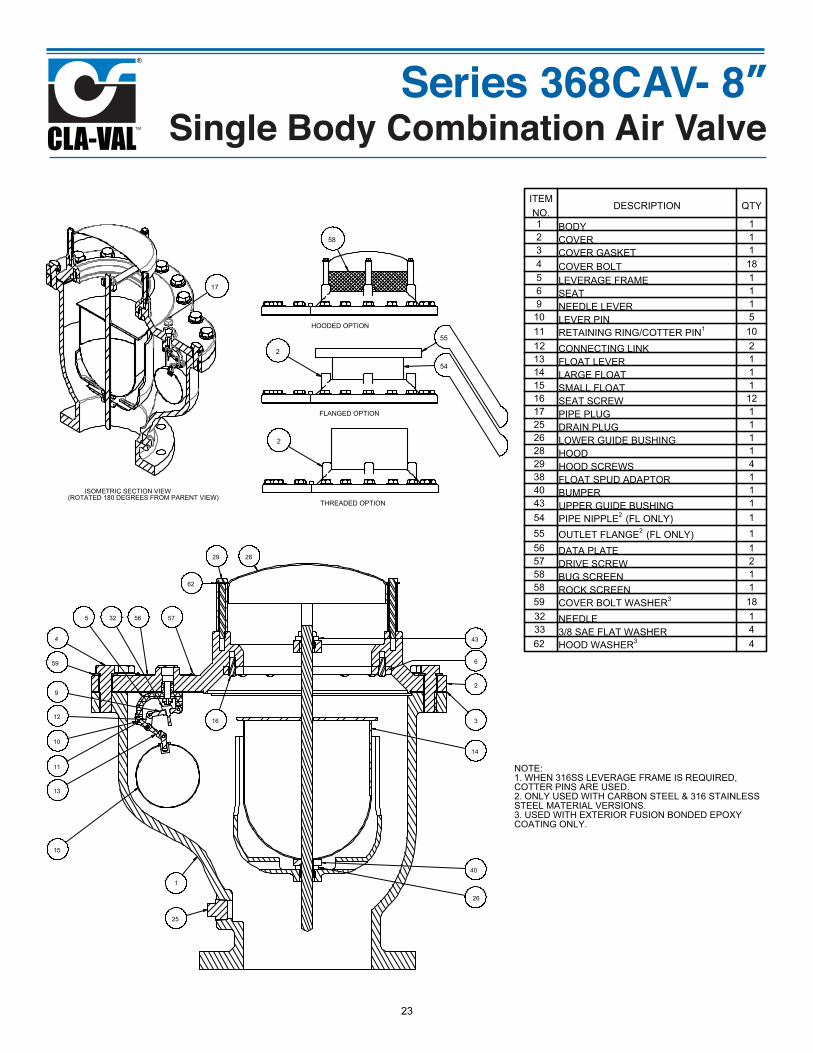
Series 368CAV- 8”Single Body Combination Air Valve
29
16
6
2
28
434
3
14
40
1
25
15
13
11
10
12
5
9
32
26
56 57
59
NOTE:1. WHEN 316SS LEVERAGE FRAME IS REQUIRED, COTTER PINS ARE USED.2. ONLY USED WITH CARBON STEEL & 316 STAINLESS STEEL MATERIAL VERSIONS.3. USED WITH EXTERIOR FUSION BONDED EPOXY COATING ONLY.
62
58
HOODED OPTION
FLANGED OPTION
2
54
55
THREADED OPTION
2
ISOMETRIC SECTION VIEW(ROTATED 180 DEGREES FROM PARENT VIEW)
17
ITEM NO.
DESCRIPTION QTY
1 BODY 12 COVER 13 COVER GASKET 14 COVER BOLT 185 LEVERAGE FRAME 16 SEAT 19 NEEDLE LEVER 110 LEVER PIN 511 RETAINING RING/COTTER PIN1 1012 CONNECTING LINK 213 FLOAT LEVER 114 LARGE FLOAT 115 SMALL FLOAT 116 SEAT SCREW 1217 PIPE PLUG 125 DRAIN PLUG 126 LOWER GUIDE BUSHING 128 HOOD 129 HOOD SCREWS 438 FLOAT SPUD ADAPTOR 140 BUMPER 143 UPPER GUIDE BUSHING 154 PIPE NIPPLE2
(FL ONLY) 155 OUTLET FLANGE2
(FL ONLY) 156 DATA PLATE 157 DRIVE SCREW 258 BUG SCREEN 158 ROCK SCREEN 159 COVER BOLT WASHER3 1832 NEEDLE 133 3/8 SAE FLAT WASHER 462 HOOD WASHER3 4
23
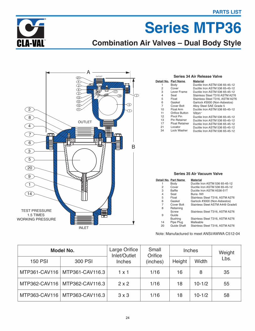
Detail No.1234567
10111213172134
Part Name BodyCoverLever FrameSeatFloatGasketCover BoltFloat ArmOrifice ButtonPivot PinPin RetainerFloat RetainerLocatorLock Washer
MaterialDuctile Iron ASTM 536 65-45-12Ductile Iron ASTM 536 65-45-12Ductile Iron ASTM 536 65-45-12Stainless Steel T316 ASTM A276Stainless Steel T316, ASTM A276Garlock #3000 (Non-Asbestos)Alloy Steel SAE Grade 5Ductile Iron ASTM 536 65-45-12VitonTM
Ductile Iron ASTM 536 65-45-12Ductile Iron ASTM 536 65-45-12Ductile Iron ASTM 536 65-45-12Ductile Iron ASTM 536 65-45-12Ductile Iron ASTM 536 65-45-12
Series 34 Air Release Valve
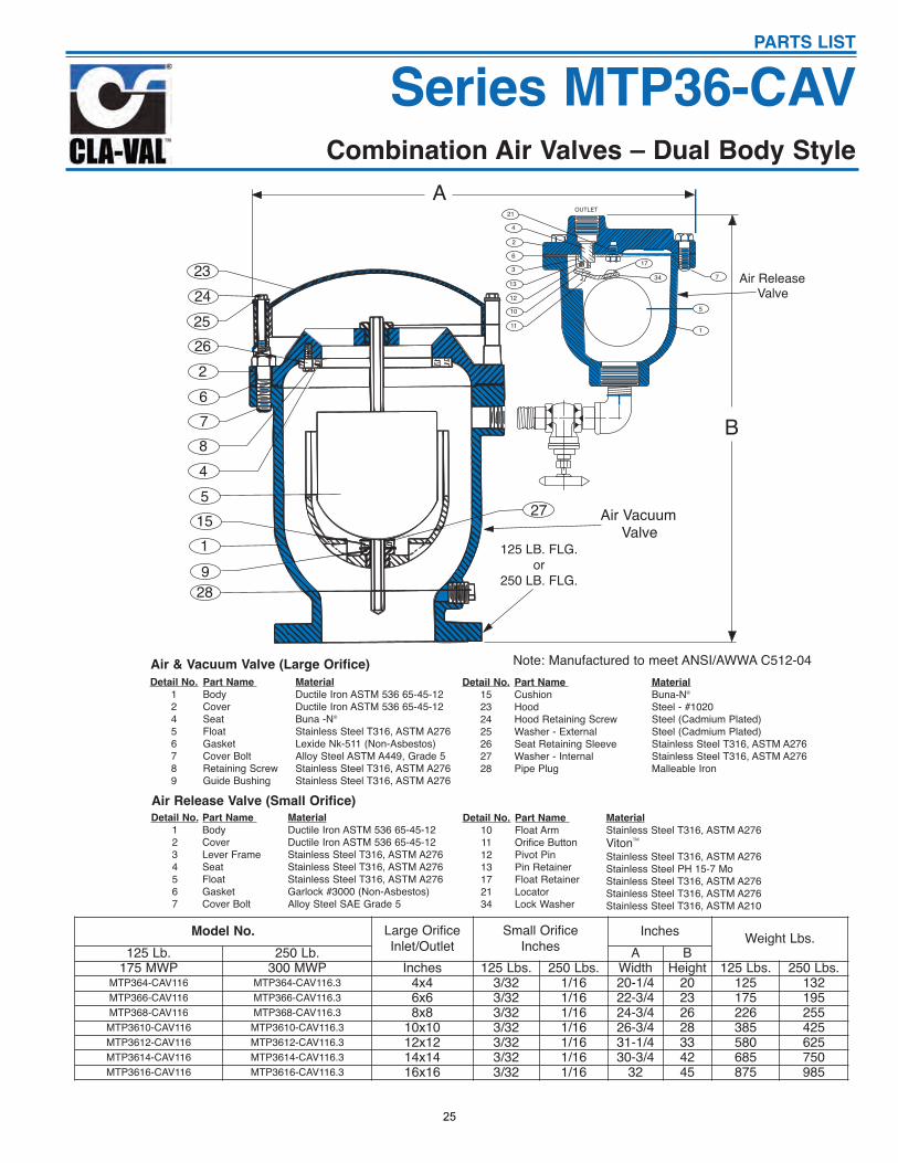
Combination Air Valves – Dual Body StyleSeries MTP36
B
INLET
OUTLET
284
76
35
20
91
14
AOUTLET21
4263
13121011
7
5
1
1734
TEST PRESSURE1.5 TIMES
WORKING PRESSURE
PARTS LIST
Detail No.12345678
9
1420
Part Name BodyCoverBaffleSeatFloatGasketCover BoltRetaining Screw Guide BushingPipe PlugGuide Shaft
MaterialDuctile Iron ASTM 536 65-45-12Ductile Iron ASTM 536 65-45-12Ductile Iron ASTM A536-51TBuna -N®Stainless Steel T316, ASTM A276Garlock #3000 (Non-Asbestos)Stainless Steel ASTM A449 Grade5
Stainless Steel T316, ASTM A276
Stainless Steel T316, ASTM A276MalleableStainless Steel T316, ASTM A276
Series 35 Air Vacuum Valve
Note: Manufactured to meet ANSI/AWWA C512-04
Model No. Large OrificeInlet/Outlet
Inches
SmallOrifice
(inches)
Inches WeightLbs.150 PSI 300 PSI Height Width
MTP361-CAV116 MTP361-CAV116.3 1 x 1 1/16 16 8 35
MTP362-CAV116 MTP362-CAV116.3 2 x 2 1/16 18 10-1/2 55
MTP363-CAV116 MTP363-CAV116.3 3 x 3 1/16 18 10-1/2 58
24
Combination Air Valves – Dual Body Style
Series MTP36-CAVPARTS LIST
Detail No.
12456789
Part Name
BodyCoverSeatFloatGasketCover BoltRetaining Screw Guide Bushing
Material
Ductile Iron ASTM 536 65-45-12Ductile Iron ASTM 536 65-45-12Buna -N®
Stainless Steel T316, ASTM A276Lexide Nk-511 (Non-Asbestos)Alloy Steel ASTM A449, Grade 5Stainless Steel T316, ASTM A276Stainless Steel T316, ASTM A276
Detail No.
1234567
Part Name
BodyCoverLever FrameSeatFloatGasketCover Bolt
Material
Ductile Iron ASTM 536 65-45-12Ductile Iron ASTM 536 65-45-12Stainless Steel T316, ASTM A276Stainless Steel T316, ASTM A276Stainless Steel T316, ASTM A276Garlock #3000 (Non-Asbestos)Alloy Steel SAE Grade 5
Detail No.
15232425262728
Part Name
CushionHoodHood Retaining ScrewWasher - ExternalSeat Retaining SleeveWasher - InternalPipe Plug
Material
Buna-N®
Steel - #1020Steel (Cadmium Plated)Steel (Cadmium Plated)Stainless Steel T316, ASTM A276Stainless Steel T316, ASTM A276Malleable Iron
Detail No.
10111213172134
Part Name
Float ArmOrifice ButtonPivot PinPin RetainerFloat RetainerLocatorLock Washer
Material
Stainless Steel T316, ASTM A276VitonTM
Stainless Steel T316, ASTM A276Stainless Steel PH 15-7 MoStainless Steel T316, ASTM A276Stainless Steel T316, ASTM A276Stainless Steel T316, ASTM A210
Air & Vacuum Valve (Large Orifice)
Air Release Valve (Small Orifice)
125 LB. FLG.or
250 LB. FLG.
23242526267845
1519
28
27
AOUTLET
21
4
2
6
3
13
12
10
11
7
5
1
17
34
B
Air VacuumValve
Air ReleaseValve
17
34
Note: Manufactured to meet ANSI/AWWA C512-04
Model No. Large OrificeInlet/Outlet
Small OrificeInches
Inches Weight Lbs.125 Lb. 250 Lb. A B
175 MWP 300 MWP Inches 125 Lbs. 250 Lbs. Width Height 125 Lbs. 250 Lbs.MTP364-CAV116 MTP364-CAV116.3 4x4 3/32 1/16 20-1/4 20 125 132MTP366-CAV116 MTP366-CAV116.3 6x6 3/32 1/16 22-3/4 23 175 195MTP368-CAV116 MTP368-CAV116.3 8x8 3/32 1/16 24-3/4 26 226 255
MTP3610-CAV116 MTP3610-CAV116.3 10x10 3/32 1/16 26-3/4 28 385 425MTP3612-CAV116 MTP3612-CAV116.3 12x12 3/32 1/16 31-1/4 33 580 625MTP3614-CAV116 MTP3614-CAV116.3 14x14 3/32 1/16 30-3/4 42 685 750MTP3616-CAV116 MTP3616-CAV116.3 16x16 3/32 1/16 32 45 875 985
25
Detail No.
1234567
10111213172134
Part Name
BodyCoverLever FrameSeatFloatGasketCover BoltFloat ArmOrifice ButtonPivot PinPin RetainerFloat RetainerLocatorLock Washer
Material
Ductile Iron ASTM 536 65-45-12Ductile Iron ASTM 536 65-45-12Stainless Steel T316 ASTM A276Stainless Steel T316 ASTM A276Stainless Steel T316 ASTM A2760Garlock #3000 (Non-Asbestos)Alloy Steel SAE Grade 5Stainless Steel T316 ASTM A276VitonTM
Stainless Steel T316 ASTM A276Stainless Steel PH 15-7 MoStainless Steel T316 ASTM A276Stainless Steel T316 ASTM A276Stainless Steel T316 ASTM A204
Air Release Valve
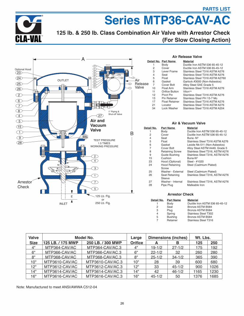
125 lb. & 250 lb. Class Combination Air Valve with Arrestor Check
OUTLET214263
13121011
7
5
1
1734
Air and VacuumValve
A
B
Arrestor Check
23242526267845
1519
28
271" Piping &Shut-off Valve
Air Release Valve
24
3
1
7
5
125 Lb. Flg.or
250 Lb. Flg.
OUTLET
INLET
E
TEST PRESSURE1.5 TIMES
WORKING PRESSURE
Optional Hood
(For Slow Closing Action)
Series MTP36-CAV-ACPARTS LIST
Detail No.
12456789
152324
2526
2728
Part Name
BodyCoverSeatFloatGasketCover BoltRetaining Screw Guide BushingCushionHood (Optional)Hood RetainingScrewWasher - ExternalSeat RetainingSleeveWasher - InternalPipe Plug
Material
Ductile Iron ASTM 536 65-45-12Ductile Iron ASTM 536 65-45-12Buna -N®
Stainless Steel T316 ASTM A276Lexide Nk-511 (Non-Asbestos)Alloy Steel ASTM A449, Grade 5Stainless Steel T316, ASTM A276Stainless Steel T316, ASTM A276Buna-N®
Steel - #1020Steel (Cadmium Plated)
Steel (Cadmium Plated)Stainless Steel T316, ASTM A276
Stainless Steel T316, ASTM A276Malleable Iron
Air & Vacuum Valve
Detail No.
123457
Part Name
BodySeatPlugSpringBushingRetainer
Arrestor Check
Material
Ductile Iron ASTM 536 65-45-12Bronze ASTM B584Bronze ASTM B584Stainless Steel T302Bronze ASTM B584Stainless Steel T316
Valve Model No. Large Dimensions (inches) Wt. Lbs.
Size 125 LB. / 175 MWP 250 LB. / 300 MWP Orifice A B 125 250
4" MTP364-CAV/AC MTP364-CAV/AC.3 4" 19-1/2 27-1/2 175 192 6" MTP366-CAV/AC MTP366-CAV/AC.3 6" 22-1/2 32 260 280 8" MTP368-CAV/AC MTP368-CAV/AC.3 8" 25-1/2 34-1/2 365 390 10" MTP3610-CAV/AC MTP3610-CAV/AC.3 10" 28 39 600 680 12" MTP3612-CAV/AC MTP3612-CAV/AC.3 12" 33 45-1/2 900 1026 14" MTP3614-CAV/AC MTP3614-CAV/AC.3 14" 42 46-1/2 1165 1230 16" MTP3616-CAV/AC MTP3616-CAV/AC.3 16" 45-1/2 50 1376 1685
Note: Manufactured to meet ANSI/AWWA C512-04
26
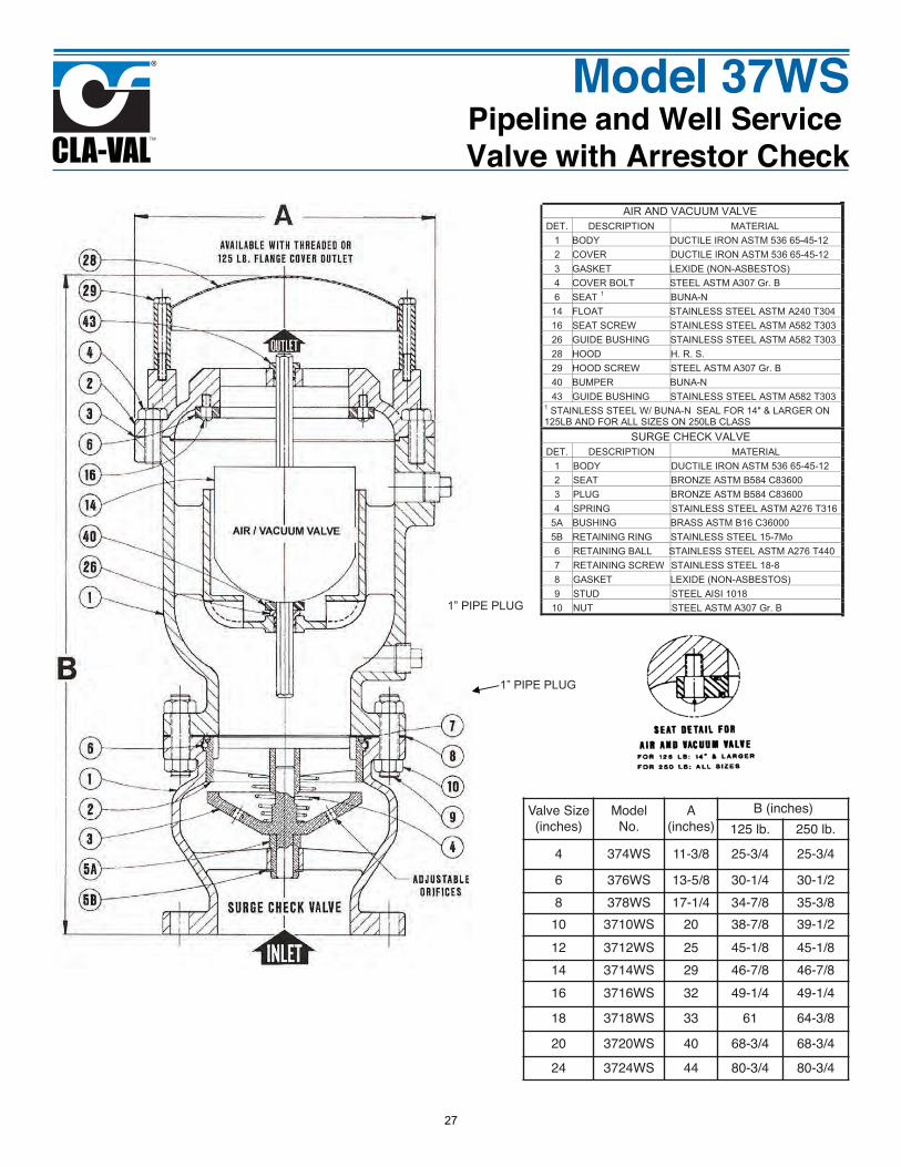
Model 37WSPipeline and Well Service Valve with Arrestor Check
AIR AND VACUUM VALVE DET. DESCRIPTION MATERIAL
1 BODY DUCTILE IRON ASTM 536 65-45-122 COVER DUCTILE IRON ASTM 536 65-45-123 GASKET LEXIDE (NON-ASBESTOS) 4 COVER BOLT STEEL ASTM A307 Gr. B 6 SEAT 1 BUNA-N
14 FLOAT STAINLESS STEEL ASTM A240 T30416 SEAT SCREW STAINLESS STEEL ASTM A582 T30326 GUIDE BUSHING STAINLESS STEEL ASTM A582 T30328 HOOD H. R. S. 29 HOOD SCREW STEEL ASTM A307 Gr. B 40 BUMPER BUNA-N 43 GUIDE BUSHING STAINLESS STEEL ASTM A582 T303
1 STAINLESS STEEL W/ BUNA-N SEAL FOR 14" & LARGER ON 125LB AND FOR ALL SIZES ON 250LB CLASS
SURGE CHECK VALVE DET. DESCRIPTION MATERIAL
1 BODY DUCTILE IRON ASTM 536 65-45-12 2 SEAT BRONZE ASTM B584 C83600 3 PLUG BRONZE ASTM B584 C83600 4 SPRING STAINLESS STEEL ASTM A276 T316
5A BUSHING BRASS ASTM B16 C36000 5B RETAINING RING STAINLESS STEEL 15-7Mo 6 RETAINING BALL STAINLESS STEEL ASTM A276 T4407 RETAINING SCREW STAINLESS STEEL 18-8 8 GASKET LEXIDE (NON-ASBESTOS) 9 STUD STEEL AISI 1018
10 NUT STEEL ASTM A307 Gr. B
1” PIPE PLUG
1” PIPE PLUG
Valve Size(inches)
Model No.
A(inches)
B (inches)125 lb. 250 lb.
4 374WS 11-3/8 25-3/4 25-3/46 376WS 13-5/8 30-1/4 30-1/28 378WS 17-1/4 34-7/8 35-3/8
10 3710WS 20 38-7/8 39-1/212 3712WS 25 45-1/8 45-1/814 3714WS 29 46-7/8 46-7/816 3716WS 32 49-1/4 49-1/418 3718WS 33 61 64-3/820 3720WS 40 68-3/4 68-3/424 3724WS 44 80-3/4 80-3/4
27
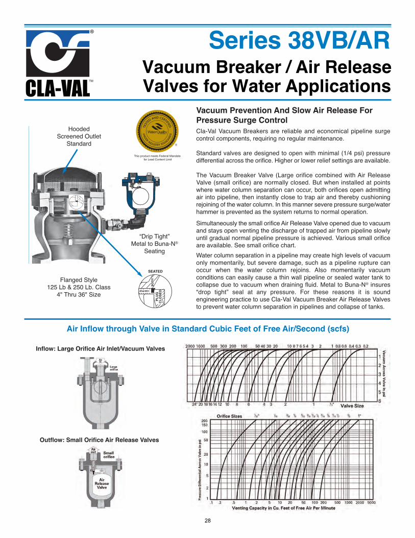
Vacuum Breaker / Air ReleaseValves for Water Applications
Series 38VB/AR
Vacuum Prevention And Slow Air Release ForPressure Surge ControlCla-Val Vacuum Breakers are reliable and economical pipeline surgecontrol components, requiring no regular maintenance.
Standard valves are designed to open with minimal (1/4 psi) pressuredifferential across the orifice. Higher or lower relief settings are available.
The Vacuum Breaker Valve (Large orifice combined with Air ReleaseValve (small orifice) are normally closed. But when installed at pointswhere water column separation can occur, both orifices open admittingair into pipeline, then instantly close to trap air and thereby cushioningrejoining of the water column. In this manner severe pressure surge/waterhammer is prevented as the system returns to normal operation.
Simultaneously the small orifice Air Release Valve opened due to vacuumand stays open venting the discharge of trapped air from pipeline slowlyuntil gradual normal pipeline pressure is achieved. Various small orificeare available. See small orifice chart.Water column separation in a pipeline may create high levels of vacuumonly momentarily, but severe damage, such as a pipeline rupture canoccur when the water column rejoins. Also momentarily vacuumconditions can easily cause a thin wall pipeline or sealed water tank tocollapse due to vacuum when draining fluid. Metal to Buna-N® insures“drop tight” seal at any pressure. For these reasons it is soundengineering practice to use Cla-Val Vacuum Breaker Air Release Valvesto prevent water column separation in pipelines and collapse of tanks.
SEATED
S E A TBODY
PLUG
CLOSED
Flanged Style125 Lb & 250 Lb. Class
4" Thru 36" Size
HoodedScreened Outlet
Standard
“Drip Tight” Metal to Buna-N®
Seating
Air Inflow through Valve in Standard Cubic Feet of Free Air/Second (scfs)
Inflow: Large Orifice Air Inlet/Vacuum Valves
This product meets Federal Mandate for Lead Content Limit
Outflow: Small Orifice Air Release Valves
28
Vacuum Breaker / Air ReleaseValves for Water Applications
Series 38VB/AR
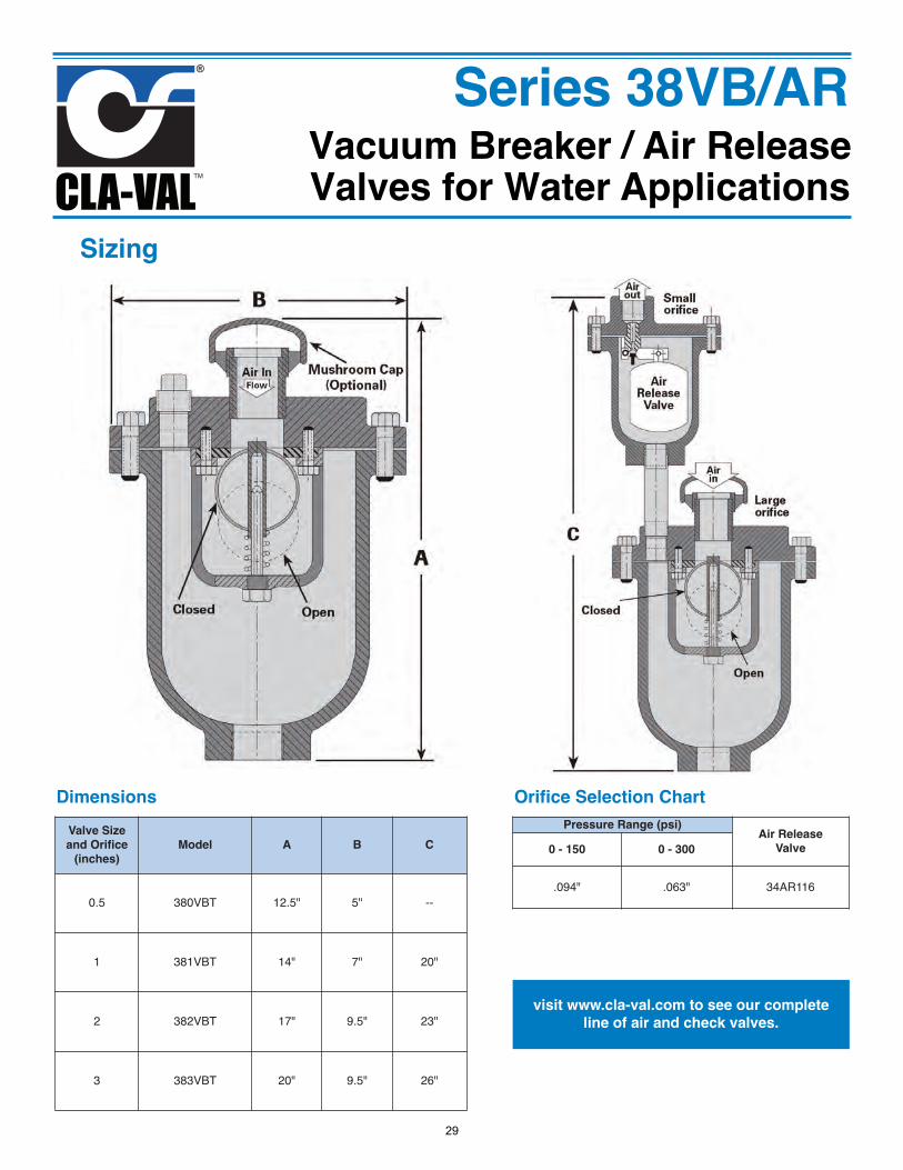
Valve Size and Orifice
(inches)Model A B C
0.5 380VBT 12.5" 5" --
1 381VBT 14" 7" 20"
2 382VBT 17" 9.5" 23"
3 383VBT 20" 9.5" 26"
Dimensions Pressure Range (psi) Air Release
Valve0 - 150 0 - 300
.094" .063" 34AR116
Orifice Selection Chart
Sizing
visit www.cla-val.com to see our completeline of air and check valves.
29
Vacuum Breaker / Air ReleaseValves for Water Applications
Series 38VB/AR
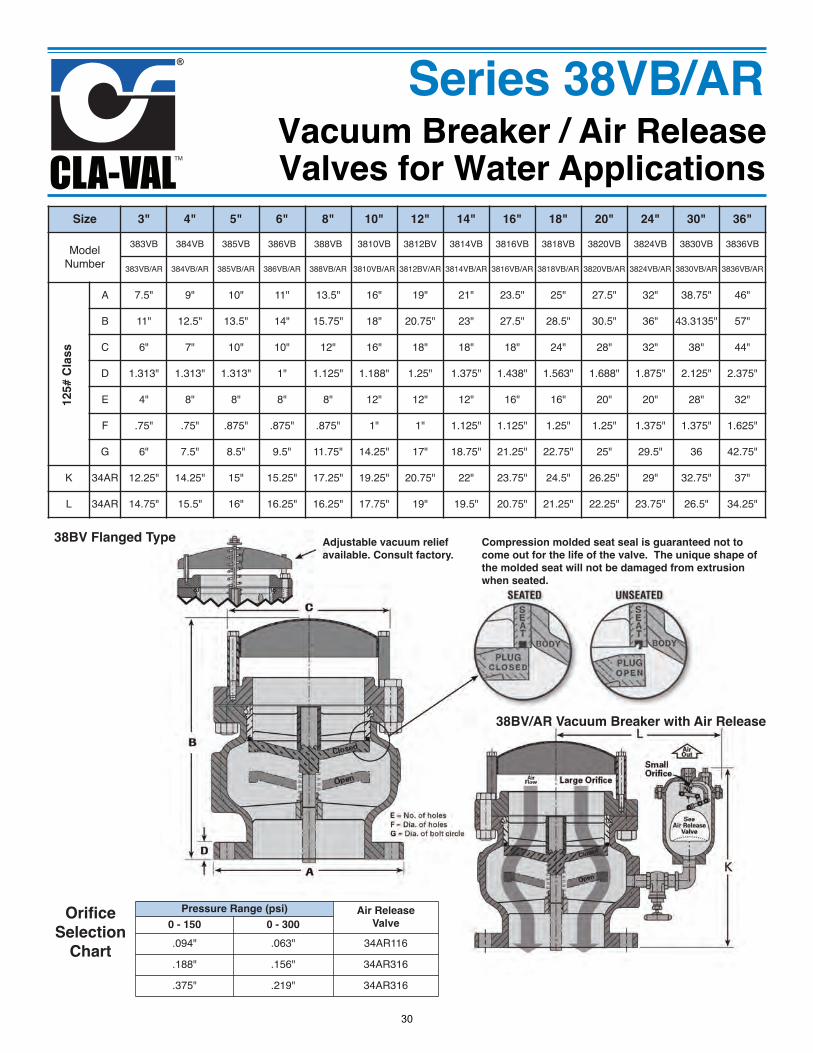
Size 3" 4" 5" 6" 8" 10" 12" 14" 16" 18" 20" 24" 30" 36"
ModelNumber
383VB 384VB 385VB 386VB 388VB 3810VB 3812BV 3814VB 3816VB 3818VB 3820VB 3824VB 3830VB 3836VB
383VB/AR 384VB/AR 385VB/AR 386VB/AR 388VB/AR 3810VB/AR 3812BV/AR 3814VB/AR 3816VB/AR 3818VB/AR 3820VB/AR 3824VB/AR 3830VB/AR 3836VB/AR
A 7.5" 9" 10" 11" 13.5" 16" 19" 21" 23.5" 25" 27.5" 32" 38.75" 46"
B 11" 12.5" 13.5" 14" 15.75" 18" 20.75" 23" 27.5" 28.5" 30.5" 36" 43.3135" 57"
C 6" 7" 10" 10" 12" 16" 18" 18" 18" 24" 28" 32" 38" 44"
D 1.313" 1.313" 1.313" 1" 1.125" 1.188" 1.25" 1.375" 1.438" 1.563" 1.688" 1.875" 2.125" 2.375"
E 4" 8" 8" 8" 8" 12" 12" 12" 16" 16" 20" 20" 28" 32"
F .75" .75" .875" .875" .875" 1" 1" 1.125" 1.125" 1.25" 1.25" 1.375" 1.375" 1.625"
G 6" 7.5" 8.5" 9.5" 11.75" 14.25" 17" 18.75" 21.25" 22.75" 25" 29.5" 36 42.75"
K 34AR 12.25" 14.25" 15" 15.25" 17.25" 19.25" 20.75" 22" 23.75" 24.5" 26.25" 29" 32.75" 37"
L 34AR 14.75" 15.5" 16" 16.25" 16.25" 17.75" 19" 19.5" 20.75" 21.25" 22.25" 23.75" 26.5" 34.25"
125# C
las
s
Adjustable vacuum relief
available. Consult factory.
38BV Flanged Type Compression molded seat seal is guaranteed not to
come out for the life of the valve. The unique shape of
the molded seat will not be damaged from extrusion
when seated.
Pressure Range (psi) Air Release
Valve0 - 150 0 - 300
.094" .063" 34AR116
.188" .156" 34AR316
.375" .219" 34AR316
38BV/AR Vacuum Breaker with Air Release
Orifice
Selection
Chart
30
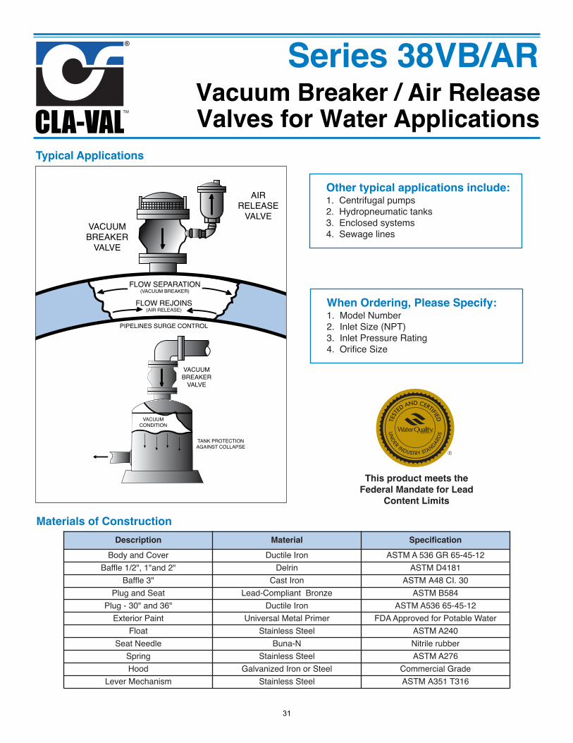
When Ordering, Please Specify:1. Model Number2. Inlet Size (NPT)3. Inlet Pressure Rating4. Orifice Size
Other typical applications include:1. Centrifugal pumps2. Hydropneumatic tanks3. Enclosed systems4. Sewage lines
Vacuum Breaker / Air ReleaseValves for Water Applications
Series 38VB/AR
VACUUMBREAKER
VALVE
AIRRELEASE
VALVE
FLOW SEPARATION(VACUUM BREAKER)
FLOW REJOINS(AIR RELEASE)
PIPELINES SURGE CONTROL
VACUUMBREAKER
VALVE
TANK PROTECTIONAGAINST COLLAPSE
VACUUMCONDITION
Typical Applications
Description Material Specification
Body and Cover Ductile Iron ASTM A 536 GR 65-45-12Baffle 1/2", 1"and 2" Delrin ASTM D4181
Baffle 3" Cast Iron ASTM A48 CI. 30Plug and Seat Lead-Compliant Bronze ASTM B584
Plug - 30" and 36" Ductile Iron ASTM A536 65-45-12Exterior Paint Universal Metal Primer FDA Approved for Potable Water
Float Stainless Steel ASTM A240Seat Needle Buna-N Nitrile rubber
Spring Stainless Steel ASTM A276Hood Galvanized Iron or Steel Commercial Grade
Lever Mechanism Stainless Steel ASTM A351 T316
Materials of Construction
This product meets the
Federal Mandate for Lead
Content Limits
31
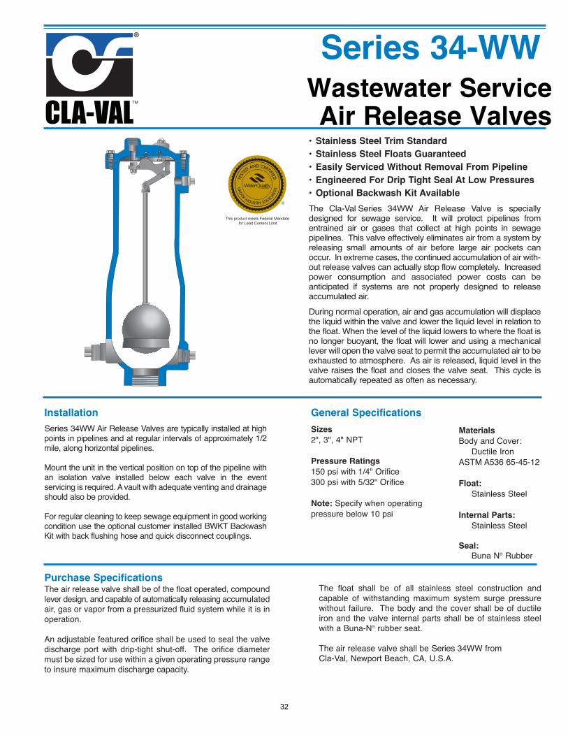
Wastewater ServiceAir Release Valves
• Stainless Steel Trim Standard
• Stainless Steel Floats Guaranteed
• Easily Serviced Without Removal From Pipeline
• Engineered For Drip Tight Seal At Low Pressures
• Optional Backwash Kit Available
The Cla-Val Series 34WW Air Release Valve is speciallydesigned for sewage service. It will protect pipelines fromentrained air or gases that collect at high points in sewagepipelines. This valve effectively eliminates air from a system byreleasing small amounts of air before large air pockets canoccur. In extreme cases, the continued accumulation of air with-out release valves can actually stop flow completely. Increasedpower consumption and associated power costs can beanticipated if systems are not properly designed to releaseaccumulated air.
During normal operation, air and gas accumulation will displacethe liquid within the valve and lower the liquid level in relation tothe float. When the level of the liquid lowers to where the float isno longer buoyant, the float will lower and using a mechanicallever will open the valve seat to permit the accumulated air to beexhausted to atmosphere. As air is released, liquid level in thevalve raises the float and closes the valve seat. This cycle isautomatically repeated as often as necessary.
Installation
Series 34WW Air Release Valves are typically installed at highpoints in pipelines and at regular intervals of approximately 1/2mile, along horizontal pipelines.
Mount the unit in the vertical position on top of the pipeline withan isolation valve installed below each valve in the eventservicing is required. A vault with adequate venting and drainageshould also be provided.
For regular cleaning to keep sewage equipment in good workingcondition use the optional customer installed BWKT BackwashKit with back flushing hose and quick disconnect couplings.
Purchase SpecificationsThe air release valve shall be of the float operated, compoundlever design, and capable of automatically releasing accumulatedair, gas or vapor from a pressurized fluid system while it is inoperation.
An adjustable featured orifice shall be used to seal the valvedischarge port with drip-tight shut-off. The orifice diametermust be sized for use within a given operating pressure rangeto insure maximum discharge capacity.
General Specifications
Sizes
2", 3", 4" NPT
Pressure Ratings
150 psi with 1/4" Orifice300 psi with 5/32" Orifice
Note: Specify when operatingpressure below 10 psi
Materials
Body and Cover:Ductile Iron
ASTM A536 65-45-12
Float:
Stainless Steel
Internal Parts:
Stainless Steel
Seal:
Buna N® Rubber
The float shall be of all stainless steel construction andcapable of withstanding maximum system surge pressurewithout failure. The body and the cover shall be of ductileiron and the valve internal parts shall be of stainless steelwith a Buna-N® rubber seat.
The air release valve shall be Series 34WW from Cla-Val, Newport Beach, CA, U.S.A.
Series 34-WW
This product meets Federal Mandate for Lead Content Limit
32
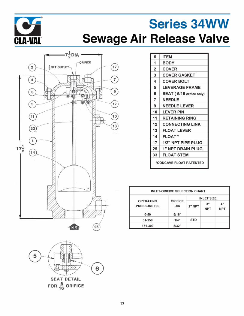
INLET-ORIFICE SELECTION CHART
OPERATING PRESSURE PSI
ORIFICE DIA
INLET SIZE
2" NPT3"
NPT 4"
NPT
0-50 5/16"
51-150 1/4" STD
151-300 5/32"
Series 34WWSewage Air Release Valve
1 BODY 2 COVER 3 COVER GASKET 4 COVER BOLT 5 LEVERAGE FRAME 6 SEAT ( 5/16 orifice only) 7 NEEDLE 9 NEEDLE LEVER 10 LEVER PIN 11 RETAINING RING 12 CONNECTING LINK 13 FLOAT LEVER 14 FLOAT * 17 1/2" NPT PIPE PLUG 25 1" NPT DRAIN PLUG 33 FLOAT STEM
*CONCAVE FLOAT PATENTED
# ITEM
33
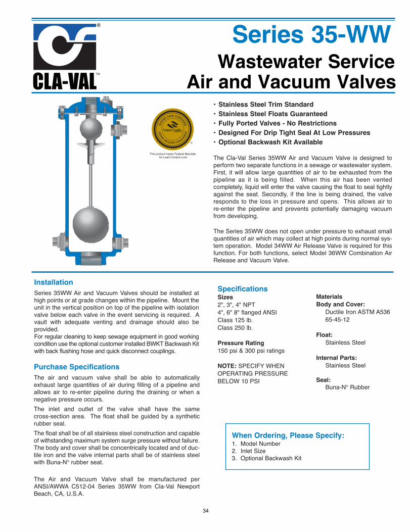
Wastewater ServiceAir and Vacuum Valves
Series 35-WW
This product meets Federal Mandate for Lead Content Limit
• Stainless Steel Trim Standard
• Stainless Steel Floats Guaranteed
• Fully Ported Valves - No Restrictions
• Designed For Drip Tight Seal At Low Pressures
• Optional Backwash Kit Available
The Cla-Val Series 35WW Air and Vacuum Valve is designed toperform two separate functions in a sewage or wastewater system.First, it will allow large quantities of air to be exhausted from thepipeline as it is being filled. When this air has been ventedcompletely, liquid will enter the valve causing the float to seal tightlyagainst the seat. Secondly, if the line is being drained, the valveresponds to the loss in pressure and opens. This allows air tore-enter the pipeline and prevents potentially damaging vacuumfrom developing.
The Series 35WW does not open under pressure to exhaust smallquantities of air which may collect at high points during normal sys-tem operation. Model 34WW Air Release Valve is required for thisfunction. For both functions, select Model 36WW Combination AirRelease and Vacuum Valve.
SpecificationsSizes
2", 3", 4" NPT 4", 6" 8" flanged ANSIClass 125 lb.Class 250 lb.
Pressure Rating
150 psi & 300 psi ratings
NOTE: SPECIFY WHENOPERATING PRESSUREBELOW 10 PSI
Materials
Body and Cover:
Ductile Iron ASTM A53665-45-12
Float:
Stainless Steel
Internal Parts:
Stainless Steel
Seal:
Buna-N® Rubber
Installation
Series 35WW Air and Vacuum Valves should be installed athigh points or at grade changes within the pipeline. Mount theunit in the vertical position on top of the pipeline with isolationvalve below each valve in the event servicing is required. Avault with adequate venting and drainage should also beprovided.For regular cleaning to keep sewage equipment in good workingcondition use the optional customer installed BWKT Backwash Kitwith back flushing hose and quick disconnect couplings.
Purchase Specifications
The air and vacuum valve shall be able to automaticallyexhaust large quantities of air during filling of a pipeline andallows air to re-enter pipeline during the draining or when anegative pressure occurs.The inlet and outlet of the valve shall have the samecross-section area. The float shall be guided by a syntheticrubber seal. The float shall be of all stainless steel construction and capableof withstanding maximum system surge pressure without failure.The body and cover shall be concentrically located and of duc-tile iron and the valve internal parts shall be of stainless steelwith Buna-N® rubber seat.
The Air and Vacuum Valve shall be manufactured perANSI/AWWA C512-04 Series 35WW from Cla-Val NewportBeach, CA, U.S.A.
When Ordering, Please Specify:1. Model Number2. Inlet Size3. Optional Backwash Kit
34
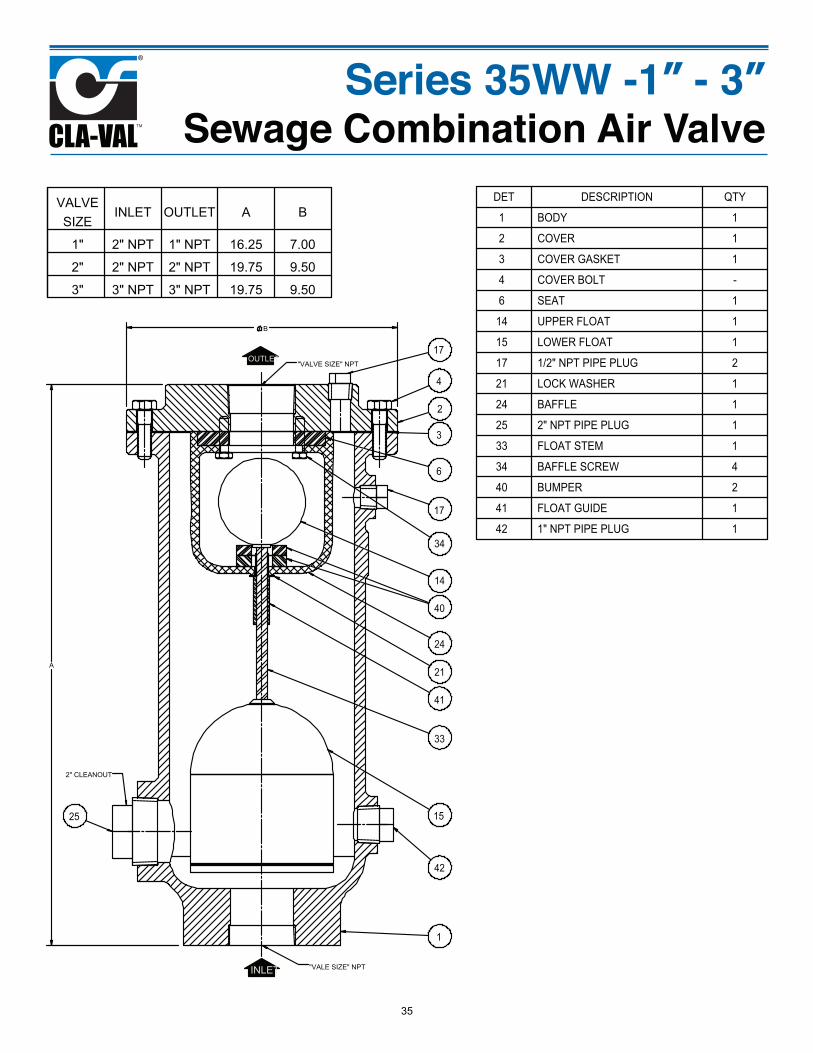
Series 35WW -1” - 3”Sewage Combination Air Valve
VALVE SIZE
INLET OUTLET A B
1" 2" NPT 1" NPT 16.25 7.00
2" 2" NPT 2" NPT 19.75 9.50
3" 3" NPT 3" NPT 19.75 9.50
DET DESCRIPTION QTY
1 BODY 1
2 COVER 1
3 COVER GASKET 1
4 COVER BOLT -
6 SEAT 1
14 UPPER FLOAT 1
15 LOWER FLOAT 1
17 1/2" NPT PIPE PLUG 2
21 LOCK WASHER 1
24 BAFFLE 1
25 2" NPT PIPE PLUG 1
33 FLOAT STEM 1
34 BAFFLE SCREW 4
40 BUMPER 2
41 FLOAT GUIDE 1
42 1" NPT PIPE PLUG 1
A
B
OUTLET
INLET
2" CLEANOUT
"VALE SIZE" NPT
"VALVE SIZE" NPT
1
2
3
4
6
14
15
17
21
24
25
33
34
40
41
42
17
35
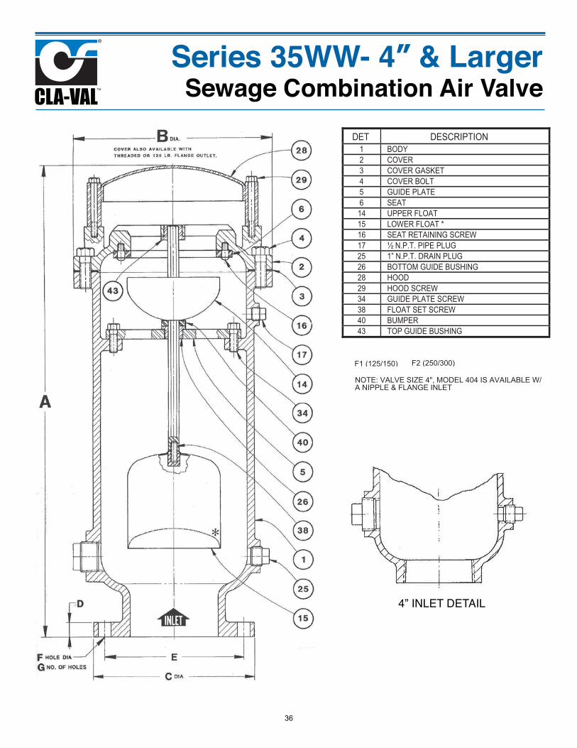
Series 35WW- 4” & LargerSewage Combination Air Valve
DET DESCRIPTION1 BODY 2 COVER 3 COVER GASKET 4 COVER BOLT 5 GUIDE PLATE 6 SEAT 14 UPPER FLOAT 15 LOWER FLOAT * 16 SEAT RETAINING SCREW 17 ½ N.P.T. PIPE PLUG 25 1” N.P.T. DRAIN PLUG 26 BOTTOM GUIDE BUSHING 28 HOOD 29 HOOD SCREW 34 GUIDE PLATE SCREW 38 FLOAT SET SCREW 40 BUMPER 43 TOP GUIDE BUSHING
F1 (125/150) F2 (250/300)
NOTE: VALVE SIZE 4", MODEL 404 IS AVAILABLE W/ A NIPPLE & FLANGE INLET
4” INLET DETAIL
36
• Stainless Steel Trim Standard
• Stainless Steel Floats Guaranteed
• Fully Ported Valves - No Restrictions
• Engineered For Drip Tight Seal At Low Pressures
• Optional Backwash Kit Available
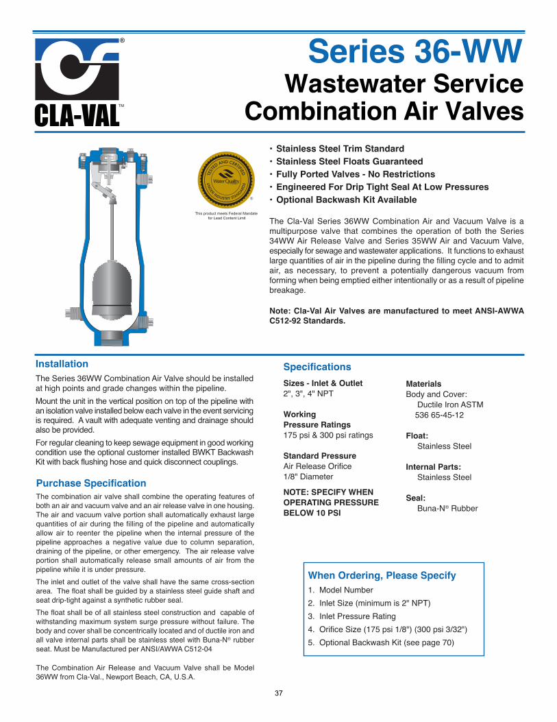
The Cla-Val Series 36WW Combination Air and Vacuum Valve is amultipurpose valve that combines the operation of both the Series34WW Air Release Valve and Series 35WW Air and Vacuum Valve,especially for sewage and wastewater applications. It functions to exhaustlarge quantities of air in the pipeline during the filling cycle and to admitair, as necessary, to prevent a potentially dangerous vacuum fromforming when being emptied either intentionally or as a result of pipelinebreakage.
Note: Cla-Val Air Valves are manufactured to meet ANSI-AWWA
C512-92 Standards.
Installation
The Series 36WW Combination Air Valve should be installedat high points and grade changes within the pipeline.Mount the unit in the vertical position on top of the pipeline withan isolation valve installed below each valve in the event servicingis required. A vault with adequate venting and drainage shouldalso be provided.For regular cleaning to keep sewage equipment in good workingcondition use the optional customer installed BWKT BackwashKit with back flushing hose and quick disconnect couplings.
Purchase Specification
The combination air valve shall combine the operating features ofboth an air and vacuum valve and an air release valve in one housing.The air and vacuum valve portion shall automatically exhaust largequantities of air during the filling of the pipeline and automaticallyallow air to reenter the pipeline when the internal pressure of thepipeline approaches a negative value due to column separation,draining of the pipeline, or other emergency. The air release valveportion shall automatically release small amounts of air from thepipeline while it is under pressure.The inlet and outlet of the valve shall have the same cross-sectionarea. The float shall be guided by a stainless steel guide shaft andseat drip-tight against a synthetic rubber seal.The float shall be of all stainless steel construction and capable ofwithstanding maximum system surge pressure without failure. Thebody and cover shall be concentrically located and of ductile iron andall valve internal parts shall be stainless steel with Buna-N® rubberseat. Must be Manufactured per ANSI/AWWA C512-04
The Combination Air Release and Vacuum Valve shall be Model36WW from Cla-Val., Newport Beach, CA, U.S.A.
Specifications
Sizes - Inlet & Outlet
2", 3", 4" NPT
Working
Pressure Ratings
175 psi & 300 psi ratings
Standard Pressure
Air Release Orifice1/8" Diameter
NOTE: SPECIFY WHEN
OPERATING PRESSURE
BELOW 10 PSI
Materials
Body and Cover:Ductile Iron ASTM
536 65-45-12
Float:
Stainless Steel
Internal Parts:
Stainless Steel
Seal:
Buna-N® Rubber
When Ordering, Please Specify
1. Model Number2. Inlet Size (minimum is 2" NPT)3. Inlet Pressure Rating4. Orifice Size (175 psi 1/8") (300 psi 3/32")5. Optional Backwash Kit (see page 70)
Wastewater ServiceCombination Air Valves
Series 36-WW
This product meets Federal Mandate for Lead Content Limit
37
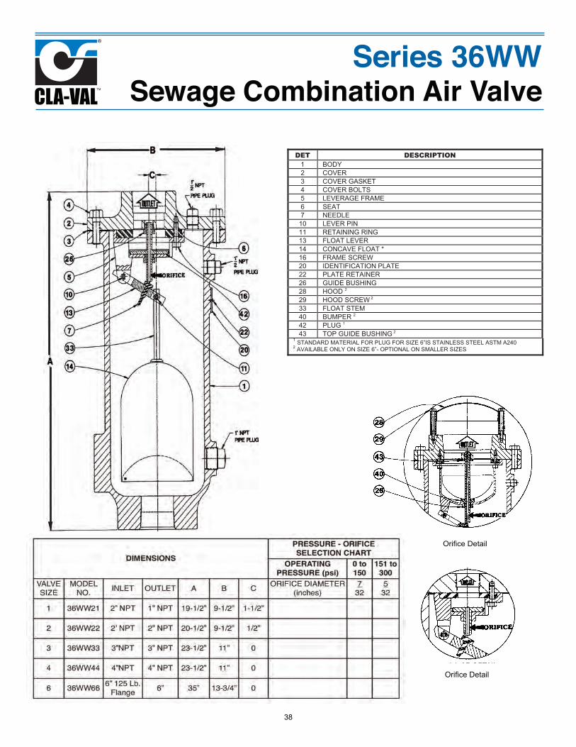
Series 36WWSewage Combination Air Valve
DET DESCRIPTION1 BODY 2 COVER 3 COVER GASKET 4 COVER BOLTS 5 LEVERAGE FRAME 6 SEAT 7 NEEDLE 10 LEVER PIN 11 RETAINING RING 13 FLOAT LEVER 14 CONCAVE FLOAT * 16 FRAME SCREW 20 IDENTIFICATION PLATE 22 PLATE RETAINER 26 GUIDE BUSHING 28 HOOD 2 29 HOOD SCREW 2 33 FLOAT STEM 40 BUMPER 2 42 PLUG 1 43 TOP GUIDE BUSHING 2
1 STANDARD MATERIAL FOR PLUG FOR SIZE 6”IS STAINLESS STEEL ASTM A240 2 AVAILABLE ONLY ON SIZE 6”- OPTIONAL ON SMALLER SIZES
Orifice Detail
Orifice Detail
38
Wafer Swing Check Valve
Recommendations for Installation Position1. Install the valve in horizontal or upward flow for proper valve closure.Caution: Do not use with reciprocating compressors, or in other pulsating services.
SPECIFICATIONSThe wafer swing check valve shall have torsional aspring-assisted fast closure to minimize possibility ofwater hammer. The valve shall be constructed ofeither cast iron or steel body.
The body shall have a machined dovetail groove toretain a field replaceable Nitrile (Buna-N®) Seal thatprovides water-tite shut-off at low/high pressure
The valve disc/arm assembly shall be one piecedesign utilizing an integral disc arm for connection tothe shalt for positive shut-off and no disc flutter.
For corrosion resistance the valve shall beElectroless Nickel Plated
Valve Body:
2" -12" Cast Iron ASTM A48 Electroless-Nickel Plated
14" - 30" Carbon Steel ASTM A216 WCB Electroless-Nickel Plated
Valve Trim:
2" - 12" 316 Stainless Steel ASTM A23, 14" - 30" Carbon Steel ASTM A216 WCB Electroless-Nickel Plated Seat O-ring: Nitrile, Other Seat Materials Available
All materials conform to ASTM specifications, The valveshall be a Cla-Val Series 501A Wafer Swing Check Valve,Newport Beach, CA 92659-0325
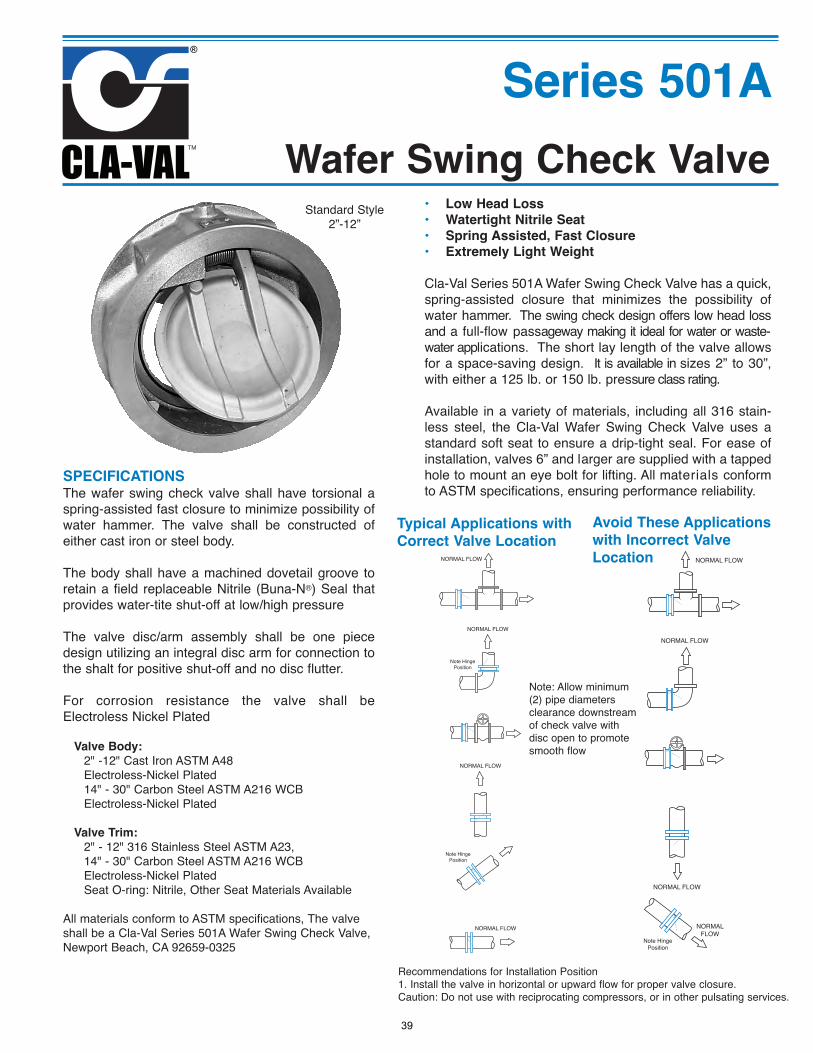
Series 501A
• Low Head Loss
• Watertight Nitrile Seat
• Spring Assisted, Fast Closure
• Extremely Light Weight
Cla-Val Series 501A Wafer Swing Check Valve has a quick,spring-assisted closure that minimizes the possibility ofwater hammer. The swing check design offers low head lossand a full-flow passageway making it ideal for water or waste-water applications. The short lay length of the valve allowsfor a space-saving design. It is available in sizes 2” to 30”,with either a 125 lb. or 150 lb. pressure class rating.
Available in a variety of materials, including all 316 stain-less steel, the Cla-Val Wafer Swing Check Valve uses astandard soft seat to ensure a drip-tight seal. For ease ofinstallation, valves 6” and larger are supplied with a tappedhole to mount an eye bolt for lifting. All materials conformto ASTM specifications, ensuring performance reliability.
NORMAL FLOW
NORMAL FLOW
NORMAL FLOW
Note HingePosition
NORMAL FLOW
Note HingePosition
NORMAL FLOW
NORMAL FLOW
NORMAL FLOW
NORMALFLOW
Note HingePosition
Typical Applications with
Correct Valve Location
Avoid These Applications
with Incorrect Valve
Location
Standard Style2”-12”
Note: Allow minimum(2) pipe diametersclearance downstreamof check valve withdisc open to promotesmooth flow
39
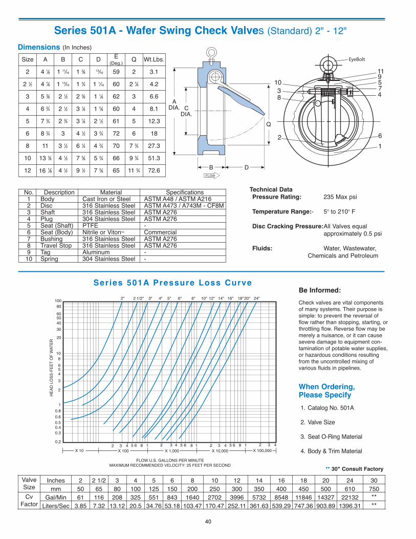
Series 501A - Wafer Swing Check Valves (Standard) 2" - 12"Dimensions (In Inches)
B D
CDIA.
ADIA.
FLOW
Q
1038
2
EyeBolt
119574
61
Technical Data
Pressure Rating: 235 Max psi
Temperature Range:- 5º to 210º F
Disc Cracking Pressure:All Valves equal approximately 0.5 psi
Fluids: Water, Wastewater, Chemicals and Petroleum
2" 3" 4" 5" 6" 6" 10" 12" 14" 16" 18"20" 24"2 1/2"1008060504030
20
1086543
2
10.80.60.50.40.3
0.22 3 4 5 6 8 1 2 3 4 5 6 8 1 2 3 4 5 6 8 1 2 3 4
FLOW U.S. GALLONS PER MINUTEMAXIMUM RECOMMENDED VELOCITY: 25 FEET PER SECOND
X 100,000X 10,000X 1,000X 100X 10
HEAD
LO
SS-F
EET
OF
WAT
ER
** 30" Consult Factory
Ser ies 501A Pressure Loss CurveBe Informed:
Check valves are vital componentsof many systems. Their purpose issimple: to prevent the reversal offlow rather than stopping, starting, orthrottling flow. Reverse flow may bemerely a nuisance, or it can causesevere damage to equipment con-tamination of potable water supplies,or hazardous conditions resultingfrom the uncontrolled mixing ofvarious fluids in pipelines.
When Ordering, Please Specify
1. Catalog No. 501A
2. Valve Size
3. Seat O-Ring Material
4. Body & Trim Material
Size A B C D E(Deg.) Q Wt.Lbs.
2 4 1⁄8 1 11⁄16 1 3⁄8 13⁄16 59 2 3.1
2 1⁄2 4 7⁄8 1 13⁄16 1 3⁄4 1 1⁄16 60 2 7⁄8 4.2
3 5 3⁄8 2 1⁄2 2 3⁄8 1 1⁄8 62 3 6.6
4 6 3⁄4 2 1⁄2 3 1⁄8 1 5⁄8 60 4 8.1
5 7 3⁄4 2 3⁄4 3 7⁄8 2 1⁄2 61 5 12.3
6 8 3⁄4 3 4 1⁄2 3 3⁄4 72 6 18
8 11 3 1⁄2 6 1⁄4 4 3⁄4 70 7 3⁄4 27.3
10 13 3⁄8 4 1⁄2 7 5⁄8 5 3⁄4 66 9 3⁄4 51.3
12 16 1⁄8 4 1⁄2 9 1⁄2 7 3⁄8 65 11 3⁄4 72.6
No. Description Material Specifications1 Body Cast Iron or Steel ASTM A48 / ASTM A2162 Disc 316 Stainless Steel ASTM A473 / A743M - CF8M3 Shaft 316 Stainless Steel ASTM A2764 Plug 304 Stainless Steel ASTM A2765 Seat (Shaft) PTFE -6 Seat (Body) Nitrile or VitonTM Commercial7 Bushing 316 Stainless Steel ASTM A2768 Travel Stop 316 Stainless Steel ASTM A2769 Tag Aluminum -
10 Spring 304 Stainless Steel -
ValveSize
Inches 2 2 1/2 3 4 5 6 8 10 12 14 16 18 20 24 30mm 50 65 80 100 125 150 200 250 300 350 400 450 500 610 750
CvFactor
Gal/Min 61 116 208 325 551 843 1640 2702 3996 5732 8548 11846 14327 22132 **Liters/Sec 3.85 7.32 13.12 20.5 34.76 53.18 103.47 170.47 252.11 361.63 539.29 747.36 903.89 1396.31 **
40
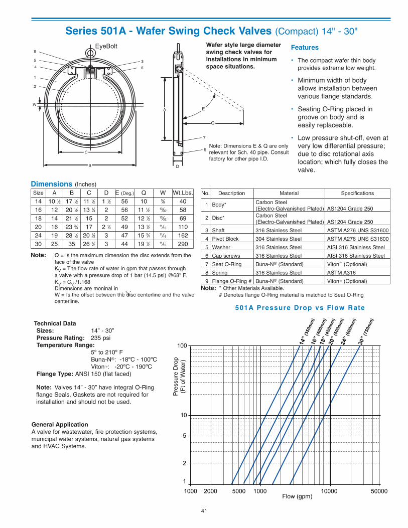
Series 501A - Wafer Swing Check Valves (Compact) 14" - 30"
Dimensions (Inches)
501A Pressure Drop vs Flow Rate
Features
• The compact wafer thin bodyprovides extreme low weight.
• Minimum width of bodyallows installation betweenvarious flange standards.
• Seating O-Ring placed ingroove on body and iseasily replaceable.
• Low pressure shut-off, even atvery low differential pressure;due to disc rotational axislocation; which fully closes thevalve.
Size A B C D E (Deg.) Q W Wt.Lbs.14 10 1⁄2 17 1⁄2 11 1⁄2 1 1⁄2 56 10 5⁄8 4016 12 20 1⁄2 13 1⁄4 2 56 11 1⁄2 13⁄32 5818 14 21 1⁄2 15 2 52 12 1⁄2 13⁄32 6920 16 23 3⁄4 17 2 1⁄3 49 13 1⁄2 11⁄16 11024 19 28 1⁄2 20 1⁄2 3 47 15 3⁄4 11⁄16 16230 25 35 26 1⁄2 3 44 19 1⁄2 11⁄16 290
No. Description Material Specifications
1 Body* Carbon Steel(Electro-Galvanished Plated) AS1204 Grade 250
2 Disc* Carbon Steel(Electro-Galvanished Plated) AS1204 Grade 250
3 Shaft 316 Stainless Steel ASTM A276 UNS S316004 Pivot Block 304 Stainless Steel ASTM A276 UNS S316005 Washer 316 Stainless Steel AISI 316 Stainless Steel6 Cap screws 316 Stainless Steel AISI 316 Stainless Steel7 Seat O-Ring Buna-N® (Standard) VitonTM (Optional)8 Spring 316 Stainless Steel ASTM A3169 Flange O-Ring # Buna-N® (Standard) VitonTM (Optional)
Wafer style large diameter
swing check valves for
installations in minimum
space situations.
Note: * Other Materials Available.# Denotes flange O-Ring material is matched to Seat O-Ring
Note: Valves 14” - 30” have integral O-Ringflange Seals, Gaskets are not required forinstallation and should not be used.
Technical Data
Sizes: 14” - 30” Pressure Rating: 235 psi Temperature Range:
5º to 210º FBuna-N®: -18ºC - 100ºCVitonTM: -20ºC - 190ºC
Flange Type: ANSI 150 (flat faced)
General Application
A valve for wastewater, fire protection systems,municipal water systems, natural gas systemsand HVAC Systems.
14”
(350
mm
)16
” (4
00m
m)
18”
(450
mm
)20
” (5
00m
m)
24” (
600m
m)
30”
(750
mm
)
100
10
11000 1000 10000
Flow (gpm)
Pre
ssur
e D
rop
(Ft o
f Wat
er)
2000 5000
2
5
50000
36
8
54
1
2
EyeBolt
W
C
B D
7
9
A
Q
E
Note: Dimensions E & Q are onlyrelevant for Sch. 40 pipe. Consultfactory for other pipe I.D.
Note: Q = Is the maximum dimension the disc extends from the face of the valveKv = The flow rate of water in gpm that passes througha valve with a pressure drop of 1 bar (14.5 psi) @68º F.Kv = Cv /1.168Dimensions are moninal inW = Is the offset between the disc centerline and the valve centerline.
41
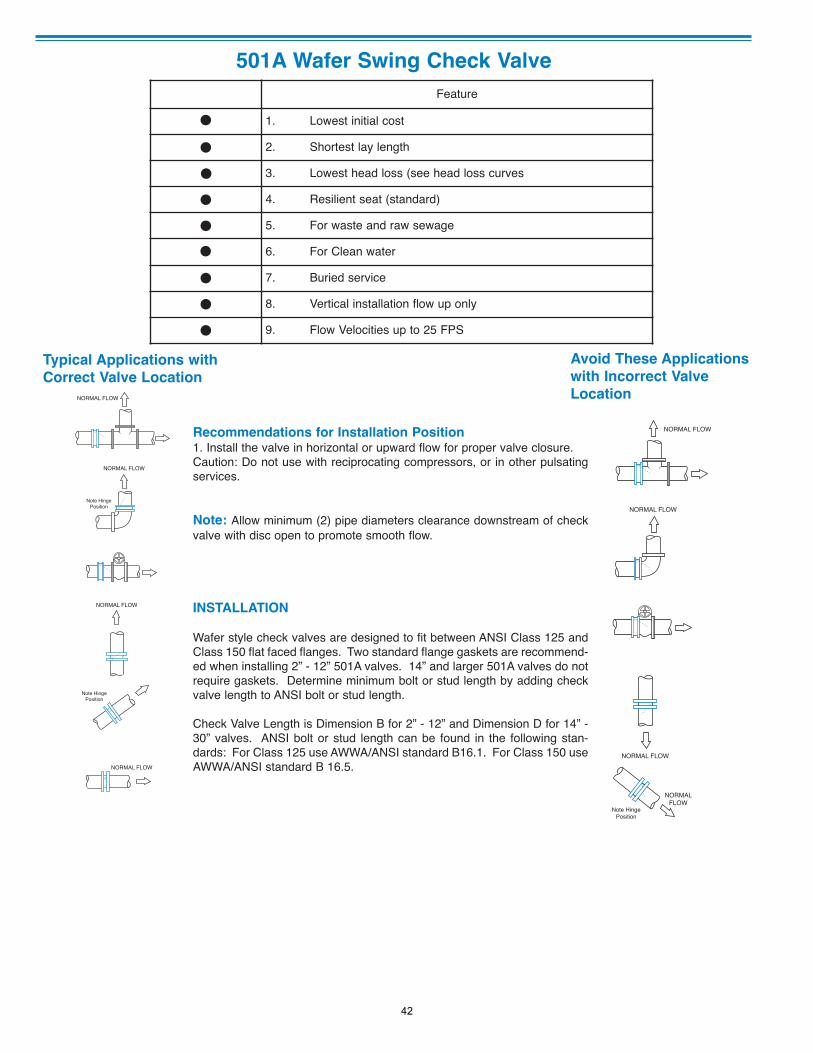
501A Wafer Swing Check Valve
Feature
1. Lowest initial cost
2. Shortest lay length
3. Lowest head loss (see head loss curves
4. Resilient seat (standard)
5. For waste and raw sewage
6. For Clean water
7. Buried service
8. Vertical installation flow up only
9. Flow Velocities up to 25 FPS
NORMAL FLOW
NORMAL FLOW
NORMAL FLOW
Note HingePosition
NORMAL FLOW
Note HingePosition NORMAL FLOW
NORMAL FLOW
NORMAL FLOW
NORMALFLOW
Note HingePosition
Typical Applications with
Correct Valve Location
Avoid These Applications
with Incorrect Valve
Location
Recommendations for Installation Position1. Install the valve in horizontal or upward flow for proper valve closure.Caution: Do not use with reciprocating compressors, or in other pulsatingservices.
Note: Allow minimum (2) pipe diameters clearance downstream of checkvalve with disc open to promote smooth flow.
INSTALLATION
Wafer style check valves are designed to fit between ANSI Class 125 andClass 150 flat faced flanges. Two standard flange gaskets are recommend-ed when installing 2” - 12” 501A valves. 14” and larger 501A valves do notrequire gaskets. Determine minimum bolt or stud length by adding checkvalve length to ANSI bolt or stud length.
Check Valve Length is Dimension B for 2” - 12” and Dimension D for 14” -30” valves. ANSI bolt or stud length can be found in the following stan-dards: For Class 125 use AWWA/ANSI standard B16.1. For Class 150 useAWWA/ANSI standard B 16.5.
42
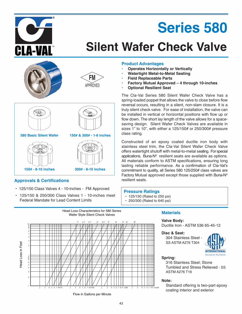
Silent Wafer Check ValveSeries 580
Product Advantages• Operates Horizontally or Vertically• Watertight Metal-to-Metal Seating• Field Replaceable Parts• Factory Mutual Approved – 4 through 10-inches• Optional Resilient Seat
150# & 300# - 1-6 inches
300# - 8-10 inches 150# - 8-10 inches
580 Basic Silent Wafer
The Cla-Val Series 580 Silent Wafer Check Valve has aspring-loaded poppet that allows the valve to close before flowreversal occurs, resulting in a silent, non-slam closure. It is atruly silent check valve. For ease of installation, the valve canbe installed in vertical or horizontal positions with flow up orflow down. The short lay length of the valve allows for a space-saving design. Silent Wafer Check Valves are available insizes 1” to 10”, with either a 125/150# or 250/300# pressureclass rating.
Constructed of an epoxy coated ductile iron body withstainless steel trim, the Cla-Val Silent Wafer Check Valveoffers watertight shutoff with metal-to-metal seating. For specialapplications, Buna-N® resilient seats are available as options.All materials conform to ASTM specifications, ensuring longlasting reliable performance. As a confirmation of Cla-Val’scommitment to quality, all Series 580 125/250# class valves areFactory Mutual approved except those supplied with Buna-N®
resilient seats.
MaterialsValve Body:Ductile Iron - ASTM 536 65-45-12
Disc & Seat:304 Stainless Steel -SS ASTM A276 T304
Spring:316 Stainless Steel; StoneTumbled and Stress Relieved - SSASTM A276 T16
Note: Standard offering is two-part epoxycoating interior and exterior
Approvals & Certifications• 125/150 Class Valves 4 - 10-inches - FM Approved• 125/150 & 250/300 Class Valves 1 - 10-inches meet
Federal Mandate for Lead Content Limits
10987
1.9.8.7
6
.6
.1
5
.5
4
.4
3
2
.3
.2
2 3 4 5 6 7 8 9 10 2 3 4 5 6 7 8 9 100 2 3 4 5 6 7 8 9 1,000 2 3 4 5 6 7 8 9 10,000
1" 11⁄4" 11⁄2" 2" 21⁄2" 3" 4" 5" 6" 8"
Head Loss Characteristics for 580 SeriesWafer Style Silent Check Valves
Flow in Gallons per Minute
Head
Los
s in
Feet
Pressure Ratings• 125/150 (Rated to 250 psi)• 250/300 (Rated to 640 psi)
43
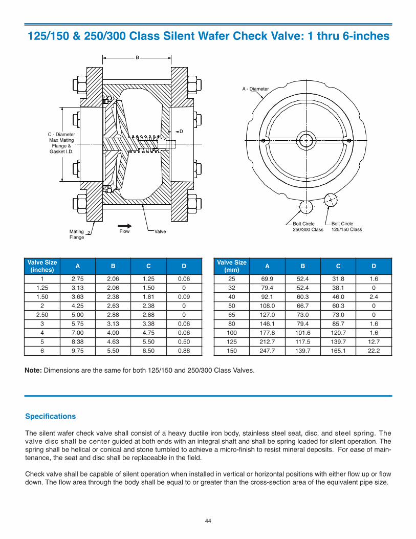
125/150 & 250/300 Class Silent Wafer Check Valve: 1 thru 6-inches
A - Diameter
Bolt Circle250/300 Class
Bolt Circle125/150 Class
B
D
MatingFlange
2 Flow Valve
C - DiameterMax Mating
Flange &Gasket I.D.
Valve Size(inches) A B C D
1 2.75 2.06 1.25 0.061.25 3.13 2.06 1.50 01.50 3.63 2.38 1.81 0.09
2 4.25 2.63 2.38 02.50 5.00 2.88 2.88 0
3 5.75 3.13 3.38 0.064 7.00 4.00 4.75 0.065 8.38 4.63 5.50 0.506 9.75 5.50 6.50 0.88
Valve Size(mm) A B C D
25 69.9 52.4 31.8 1.632 79.4 52.4 38.1 040 92.1 60.3 46.0 2.450 108.0 66.7 60.3 065 127.0 73.0 73.0 080 146.1 79.4 85.7 1.6
100 177.8 101.6 120.7 1.6125 212.7 117.5 139.7 12.7150 247.7 139.7 165.1 22.2
Note: Dimensions are the same for both 125/150 and 250/300 Class Valves.
Specifications
The silent wafer check valve shall consist of a heavy ductile iron body, stainless steel seat, disc, and steel spring. Thevalve disc shall be center guided at both ends with an integral shaft and shall be spring loaded for silent operation. Thespring shall be helical or conical and stone tumbled to achieve a micro-finish to resist mineral deposits. For ease of main-tenance, the seat and disc shall be replaceable in the field.
Check valve shall be capable of silent operation when installed in vertical or horizontal positions with either flow up or flowdown. The flow area through the body shall be equal to or greater than the cross-section area of the equivalent pipe size.
44
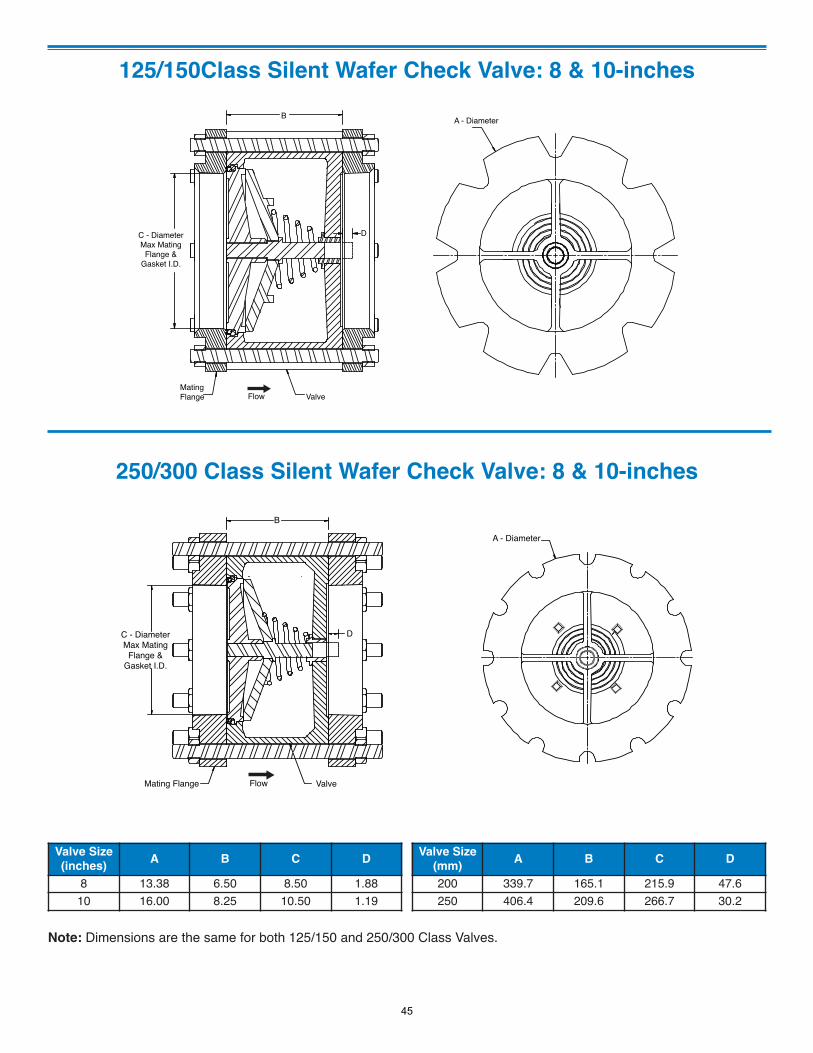
125/150Class Silent Wafer Check Valve: 8 & 10-inchesA - DiameterB
D
MatingFlange Flow Valve
C - DiameterMax Mating
Flange &Gasket I.D.
Valve Size(inches) A B C D
8 13.38 6.50 8.50 1.8810 16.00 8.25 10.50 1.19
Valve Size(mm) A B C D
200 339.7 165.1 215.9 47.6250 406.4 209.6 266.7 30.2
250/300 Class Silent Wafer Check Valve: 8 & 10-inches
A - Diameter
B
D
Mating Flange Flow Valve
C - DiameterMax Mating
Flange &Gasket I.D.
Note: Dimensions are the same for both 125/150 and 250/300 Class Valves.
45
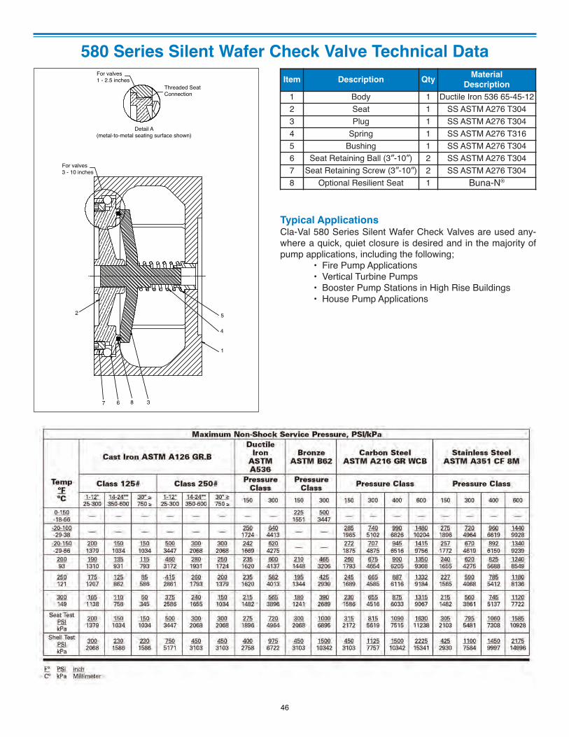
580 Series Silent Wafer Check Valve Technical DataFor valves1 - 2.5 inches
Threaded SeatConnection
Detail A(metal-to-metal seating surface shown)
For valves3 - 10 inches
5
4
1
3867
2
Item Description Qty MaterialDescription
1 Body 1 Ductile Iron 536 65-45-122 Seat 1 SS ASTM A276 T3043 Plug 1 SS ASTM A276 T3044 Spring 1 SS ASTM A276 T3165 Bushing 1 SS ASTM A276 T3046 Seat Retaining Ball (3”-10”) 2 SS ASTM A276 T3047 Seat Retaining Screw (3”-10”) 2 SS ASTM A276 T3048 Optional Resilient Seat 1 Buna-N®
Typical ApplicationsCla-Val 580 Series Silent Wafer Check Valves are used any-where a quick, quiet closure is desired and in the majority ofpump applications, including the following;
• Fire Pump Applications• Vertical Turbine Pumps• Booster Pump Stations in High Rise Buildings• House Pump Applications
46
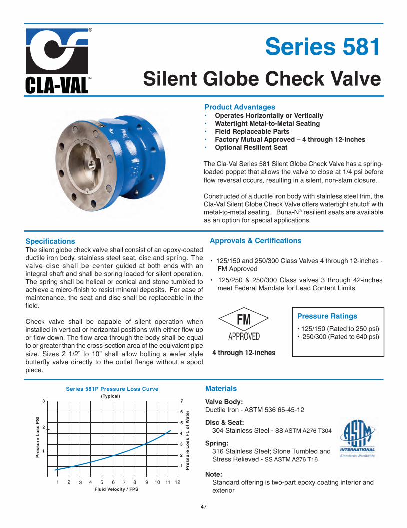
Silent Globe Check ValveSeries 581
Product Advantages• Operates Horizontally or Vertically• Watertight Metal-to-Metal Seating• Field Replaceable Parts• Factory Mutual Approved – 4 through 12-inches• Optional Resilient Seat
The Cla-Val Series 581 Silent Globe Check Valve has a spring-loaded poppet that allows the valve to close at 1/4 psi beforeflow reversal occurs, resulting in a silent, non-slam closure.
Constructed of a ductile iron body with stainless steel trim, theCla-Val Silent Globe Check Valve offers watertight shutoff withmetal-to-metal seating. Buna-N® resilient seats are availableas an option for special applications,
SpecificationsThe silent globe check valve shall consist of an epoxy-coatedductile iron body, stainless steel seat, disc and spring. Thevalve disc shall be center guided at both ends with anintegral shaft and shall be spring loaded for silent operation.The spring shall be helical or conical and stone tumbled toachieve a micro-finish to resist mineral deposits. For ease ofmaintenance, the seat and disc shall be replaceable in thefield.
Check valve shall be capable of silent operation wheninstalled in vertical or horizontal positions with either flow upor flow down. The flow area through the body shall be equalto or greater than the cross-section area of the equivalent pipesize. Sizes 2 1/2” to 10” shall allow bolting a wafer stylebutterfly valve directly to the outlet flange without a spoolpiece.
1 2 3 4 5 6 7 8 9 10 11 12
Series 581P Pressure Loss Curve
3
2
1
7
6
5
4
3
2
1
Pres
sure
Los
s PS
I
Pres
sure
Los
s Ft
. of W
ater
Fluid Velocity / FPS
(Typical)
Approvals & Certifications
• 125/150 and 250/300 Class Valves 4 through 12-inches -FM Approved
• 125/250 & 250/300 Class valves 3 through 42-inchesmeet Federal Mandate for Lead Content Limits
MaterialsValve Body:Ductile Iron - ASTM 536 65-45-12
Disc & Seat:304 Stainless Steel - SS ASTM A276 T304
Spring:316 Stainless Steel; Stone Tumbled andStress Relieved - SS ASTM A276 T16
Note: Standard offering is two-part epoxy coating interior andexterior
4 through 12-inches
Pressure Ratings• 125/150 (Rated to 250 psi)• 250/300 (Rated to 640 psi)
47
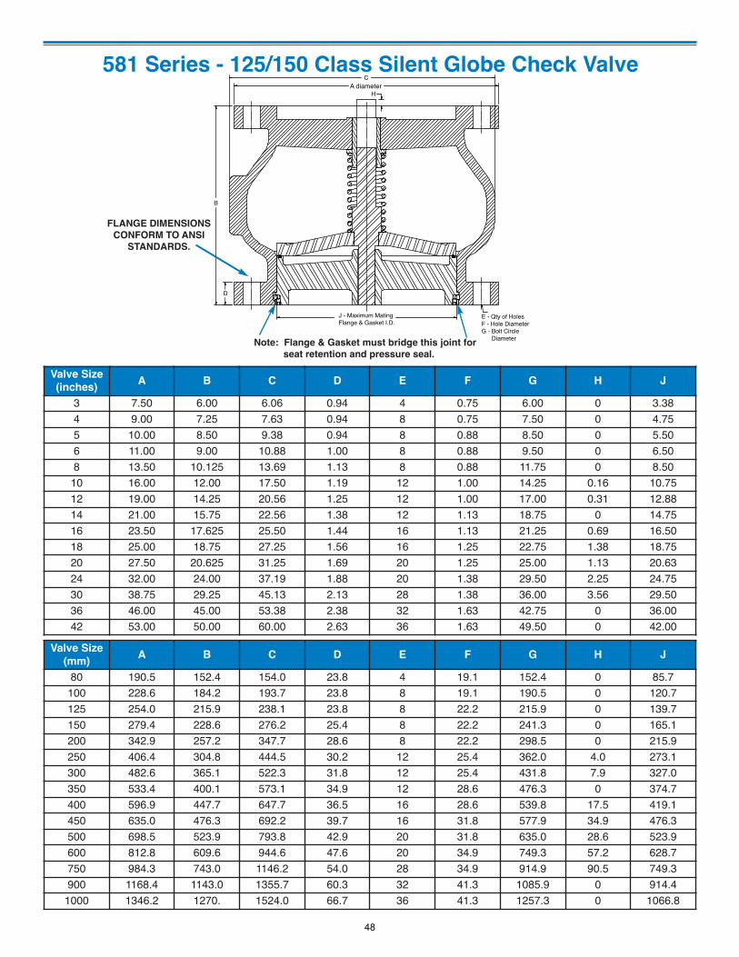
581 Series - 125/150 Class Silent Globe Check Valve
CA diameter
H
D
J - Maximum Mating Flange & Gasket I.D.
E - Qty of HolesF - Hole DiameterG - Bolt Circle Diameter
B
Valve Size
(inches)A B C D E F G H J
3 7.50 6.00 6.06 0.94 4 0.75 6.00 0 3.384 9.00 7.25 7.63 0.94 8 0.75 7.50 0 4.755 10.00 8.50 9.38 0.94 8 0.88 8.50 0 5.506 11.00 9.00 10.88 1.00 8 0.88 9.50 0 6.508 13.50 10.125 13.69 1.13 8 0.88 11.75 0 8.50
10 16.00 12.00 17.50 1.19 12 1.00 14.25 0.16 10.7512 19.00 14.25 20.56 1.25 12 1.00 17.00 0.31 12.8814 21.00 15.75 22.56 1.38 12 1.13 18.75 0 14.7516 23.50 17.625 25.50 1.44 16 1.13 21.25 0.69 16.5018 25.00 18.75 27.25 1.56 16 1.25 22.75 1.38 18.7520 27.50 20.625 31.25 1.69 20 1.25 25.00 1.13 20.6324 32.00 24.00 37.19 1.88 20 1.38 29.50 2.25 24.7530 38.75 29.25 45.13 2.13 28 1.38 36.00 3.56 29.5036 46.00 45.00 53.38 2.38 32 1.63 42.75 0 36.0042 53.00 50.00 60.00 2.63 36 1.63 49.50 0 42.00
Valve Size
(mm)A B C D E F G H J
80 190.5 152.4 154.0 23.8 4 19.1 152.4 0 85.7100 228.6 184.2 193.7 23.8 8 19.1 190.5 0 120.7125 254.0 215.9 238.1 23.8 8 22.2 215.9 0 139.7150 279.4 228.6 276.2 25.4 8 22.2 241.3 0 165.1200 342.9 257.2 347.7 28.6 8 22.2 298.5 0 215.9250 406.4 304.8 444.5 30.2 12 25.4 362.0 4.0 273.1300 482.6 365.1 522.3 31.8 12 25.4 431.8 7.9 327.0350 533.4 400.1 573.1 34.9 12 28.6 476.3 0 374.7400 596.9 447.7 647.7 36.5 16 28.6 539.8 17.5 419.1450 635.0 476.3 692.2 39.7 16 31.8 577.9 34.9 476.3500 698.5 523.9 793.8 42.9 20 31.8 635.0 28.6 523.9600 812.8 609.6 944.6 47.6 20 34.9 749.3 57.2 628.7750 984.3 743.0 1146.2 54.0 28 34.9 914.9 90.5 749.3900 1168.4 1143.0 1355.7 60.3 32 41.3 1085.9 0 914.4
1000 1346.2 1270. 1524.0 66.7 36 41.3 1257.3 0 1066.8
Note: Flange & Gasket must bridge this joint for
seat retention and pressure seal.
FLANGE DIMENSIONS
CONFORM TO ANSI
STANDARDS.
48
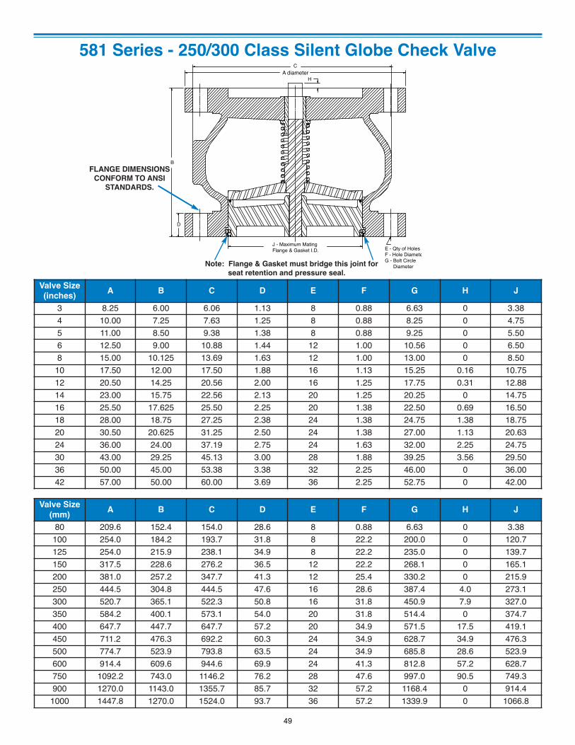
581 Series - 250/300 Class Silent Globe Check Valve
CA diameter
H
D
J - Maximum Mating Flange & Gasket I.D. E - Qty of Holes
F - Hole DiameteG - Bolt Circle Diameter
B
Valve Size
(inches)A B C D E F G H J
3 8.25 6.00 6.06 1.13 8 0.88 6.63 0 3.384 10.00 7.25 7.63 1.25 8 0.88 8.25 0 4.755 11.00 8.50 9.38 1.38 8 0.88 9.25 0 5.506 12.50 9.00 10.88 1.44 12 1.00 10.56 0 6.508 15.00 10.125 13.69 1.63 12 1.00 13.00 0 8.50
10 17.50 12.00 17.50 1.88 16 1.13 15.25 0.16 10.7512 20.50 14.25 20.56 2.00 16 1.25 17.75 0.31 12.8814 23.00 15.75 22.56 2.13 20 1.25 20.25 0 14.7516 25.50 17.625 25.50 2.25 20 1.38 22.50 0.69 16.5018 28.00 18.75 27.25 2.38 24 1.38 24.75 1.38 18.7520 30.50 20.625 31.25 2.50 24 1.38 27.00 1.13 20.6324 36.00 24.00 37.19 2.75 24 1.63 32.00 2.25 24.7530 43.00 29.25 45.13 3.00 28 1.88 39.25 3.56 29.5036 50.00 45.00 53.38 3.38 32 2.25 46.00 0 36.0042 57.00 50.00 60.00 3.69 36 2.25 52.75 0 42.00
Valve Size
(mm)A B C D E F G H J
80 209.6 152.4 154.0 28.6 8 0.88 6.63 0 3.38100 254.0 184.2 193.7 31.8 8 22.2 200.0 0 120.7125 254.0 215.9 238.1 34.9 8 22.2 235.0 0 139.7150 317.5 228.6 276.2 36.5 12 22.2 268.1 0 165.1200 381.0 257.2 347.7 41.3 12 25.4 330.2 0 215.9250 444.5 304.8 444.5 47.6 16 28.6 387.4 4.0 273.1300 520.7 365.1 522.3 50.8 16 31.8 450.9 7.9 327.0350 584.2 400.1 573.1 54.0 20 31.8 514.4 0 374.7400 647.7 447.7 647.7 57.2 20 34.9 571.5 17.5 419.1450 711.2 476.3 692.2 60.3 24 34.9 628.7 34.9 476.3500 774.7 523.9 793.8 63.5 24 34.9 685.8 28.6 523.9600 914.4 609.6 944.6 69.9 24 41.3 812.8 57.2 628.7750 1092.2 743.0 1146.2 76.2 28 47.6 997.0 90.5 749.3900 1270.0 1143.0 1355.7 85.7 32 57.2 1168.4 0 914.4
1000 1447.8 1270.0 1524.0 93.7 36 57.2 1339.9 0 1066.8
FLANGE DIMENSIONS
CONFORM TO ANSI
STANDARDS.
Note: Flange & Gasket must bridge this joint for
seat retention and pressure seal.
49
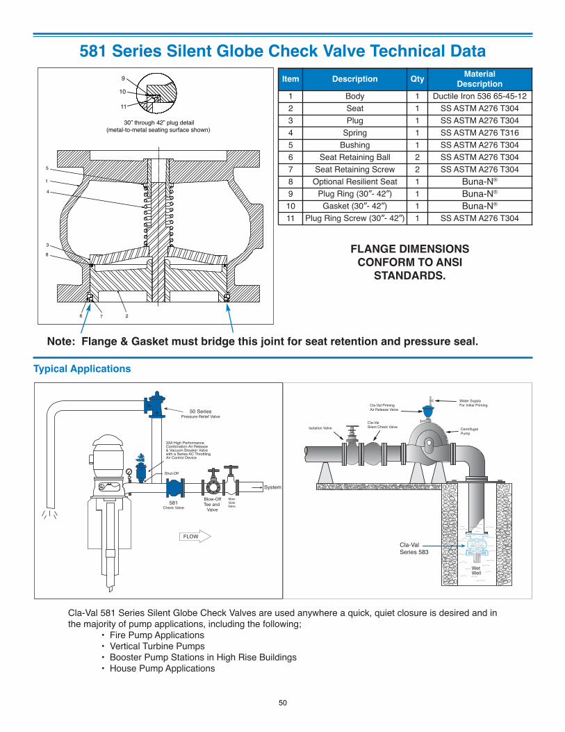
581 Series Silent Globe Check Valve Technical Data
30” through 42” plug detail(metal-to-metal seating surface shown)
11
10
9
1
7
8
6
5
4
3
2
Item Description QtyMaterial
Description
1 Body 1 Ductile Iron 536 65-45-122 Seat 1 SS ASTM A276 T3043 Plug 1 SS ASTM A276 T3044 Spring 1 SS ASTM A276 T3165 Bushing 1 SS ASTM A276 T3046 Seat Retaining Ball 2 SS ASTM A276 T3047 Seat Retaining Screw 2 SS ASTM A276 T3048 Optional Resilient Seat 1 Buna-N®
9 Plug Ring (30”- 42”) 1 Buna-N®
10 Gasket (30”- 42”) 1 Buna-N®
11 Plug Ring Screw (30”- 42”) 1 SS ASTM A276 T304
Cla-Val 581 Series Silent Globe Check Valves are used anywhere a quick, quiet closure is desired and inthe majority of pump applications, including the following;
• Fire Pump Applications• Vertical Turbine Pumps• Booster Pump Stations in High Rise Buildings• House Pump Applications
Typical Applications
FLOW
33A High Performance Combination Air Release & Vacuum Breaker Valve with a Series AC Throttling Air Control Device
581 Check Valve
Blow-OffTee and
Valve
Main Gate Valve
Shut-Off
System
50 SeriesPressure Relief Valve
Cla-Val PrimingAir Release Valve
Water SupplyFor Initial Priming
CentrifugalPump
WetWell
Cla-ValSilent Check ValveIsolation Valve
Cla-ValSeries 583
FLANGE DIMENSIONS
CONFORM TO ANSI
STANDARDS.
Note: Flange & Gasket must bridge this joint for seat retention and pressure seal.
50
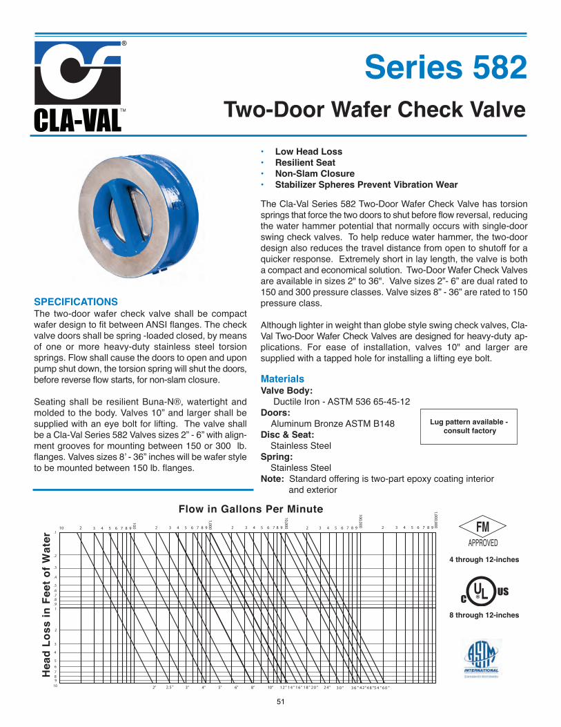
MaterialsValve Body:
Ductile Iron - ASTM 536 65-45-12Doors:
Aluminum Bronze ASTM B148Disc & Seat:
Stainless Steel Spring:
Stainless Steel Note: Standard offering is two-part epoxy coating interior
and exterior
4 through 12-inches
Series 582
SPECIFICATIONSThe two-door wafer check valve shall be compactwafer design to fit between ANSI flanges. The checkvalve doors shall be spring -loaded closed, by meansof one or more heavy-duty stainless steel torsionsprings. Flow shall cause the doors to open and uponpump shut down, the torsion spring will shut the doors,before reverse flow starts, for non-slam closure.
Seating shall be resilient Buna-N®, watertight andmolded to the body. Valves 10” and larger shall besupplied with an eye bolt for lifting. The valve shallbe a Cla-Val Series 582 Valves sizes 2” - 6” with align-ment grooves for mounting between 150 or 300 lb.flanges. Valves sizes 8’ - 36” inches will be wafer styleto be mounted between 150 lb. flanges.
1,000,000
98765432
100,000
98765432
10,00098765432
1,00098765432
100
987654310.1
.2
.3
.4
.5
.6
.7
.8
.91
6 0 "5 4 "4 8 "4 2 "3 6 "3 0 "2 4 "2 0 "1 8 "1 6 "1 4 "1 2 "10"8"6"5"4"3"2"
Flow in Gallons Per Minute
Head
Los
s in
Fee
t of W
ater
2.5 "
2
3
4
5
6789
10
The Cla-Val Series 582 Two-Door Wafer Check Valve has torsionsprings that force the two doors to shut before flow reversal, reducingthe water hammer potential that normally occurs with single-doorswing check valves. To help reduce water hammer, the two-doordesign also reduces the travel distance from open to shutoff for aquicker response. Extremely short in lay length, the valve is botha compact and economical solution. Two-Door Wafer Check Valvesare available in sizes 2" to 36". Valve sizes 2”- 6” are dual rated to150 and 300 pressure classes. Valve sizes 8” - 36” are rated to 150pressure class.
Although lighter in weight than globe style swing check valves, Cla-Val Two-Door Wafer Check Valves are designed for heavy-duty ap-plications. For ease of installation, valves 10" and larger aresupplied with a tapped hole for installing a lifting eye bolt.
• Low Head Loss• Resilient Seat• Non-Slam Closure• Stabilizer Spheres Prevent Vibration Wear
Two-Door Wafer Check Valve
UL®CUS
8 through 12-inches
Lug pattern available -consult factory
51
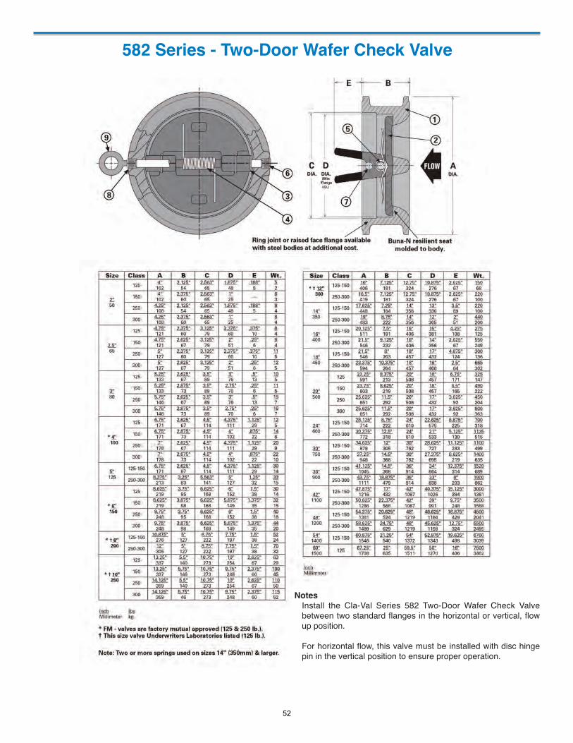
582 Series - Two-Door Wafer Check Valve
NotesInstall the Cla-Val Series 582 Two-Door Wafer Check Valvebetween two standard flanges in the horizontal or vertical, flowup position.
For horizontal flow, this valve must be installed with disc hingepin in the vertical position to ensure proper operation.
52
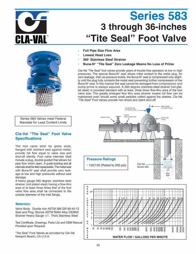
Cla-Val PrimingAir Release Valve
Water SupplyFor Initial Priming
CentrifugalPump
Wet Well
Cla-ValSilent Check ValveIsolation Valve
Cla-ValSeries 583
Series 583
“Tite Seal” Foot Valve
Valve Body: Ductile Iron ASTM 586 GR 65-45-12Seat and Plug: Bronze ASTM B584 Alloy C83600 Strainer Heavy Gauge 1⁄16": Thick Stainless Steel
Test Certificate, Drawings, Parts List and O&M ManualProvided upon Request.
“Tite Seal” Foot Valves as provided by Cla-ValNewport Beach, CA U.S.A.
Cla-Val “Tite Seal” foot valves provide years of trouble free operation at low or highpressures. The special Buna-N® seal allows initial contact to the metal plug, forzero leakage, then as pressure builds, the Buna-N® seal is compressed only slight-ly until the plug fully contacts the metal seat preventing further compression of theBuna-N® seal. In this manner the seal cannot be damaged from compression andpump prime is always assured. A 360 degree stainless steel strainer (not plat-ed steel) is provided standard with at least, three times flow-thru area of the footvalve size. This greatly enlarged flow thru area strainer means full flow can bemaintained even should some small particles collect against the strainer. Cla-Val“Tite Seal” Foot Valves provide non-shock and silent shut-off.
• Full Pipe Size Flow Area
• Lowest Head Loss
• 360º Stainless Steel Strainer
• Buna-N® “Tite Seal” Zero Leakage Means No Loss of Prime
Materials:
Cla-Val “Tite Seal” Foot Valve
Specifications
The foot valve shall be globe style,flanged with resilient seal against metal;provide full flow equal to valve size andshut-off silently. Foot valve internals shallinclude a plug, double guided that allows fullpipe flow when open. A guide bushing and allinternals shall be field replaceable. The metal seatwith Buna-N® seal shall provide zero leak-age at low and high pressures without sealdamage. A heavy gauge 360 degree, stainless steelstrainer (not plated steel) having a flow-thruarea of at least three times that of the footvalve flow area shall be connected to theoutside diameter of the inlet flange.
2 2.5 3 4 5 6 8 10 12 14 16 18 20 24 30 36
20 30 40 50 60 70 80 100
200
300
400
500
600
700
800
1000
2000
3000
4000
5000
6000
7000
8000
1000
0
2000
0
3000
040
000
5000
0
20
10876543
2
1
WATER FLOW / GALLONS PER MINUTE
H
E
A
D
L
O
S
S
/
F
E
E
T
O
F
W
A
T
E
R
Series 583 Valves meet FederalMandate for Lead Content Limits
Pressure Ratings
• 125/150 (Rated to 250 psi)
3 through 36-inches
53
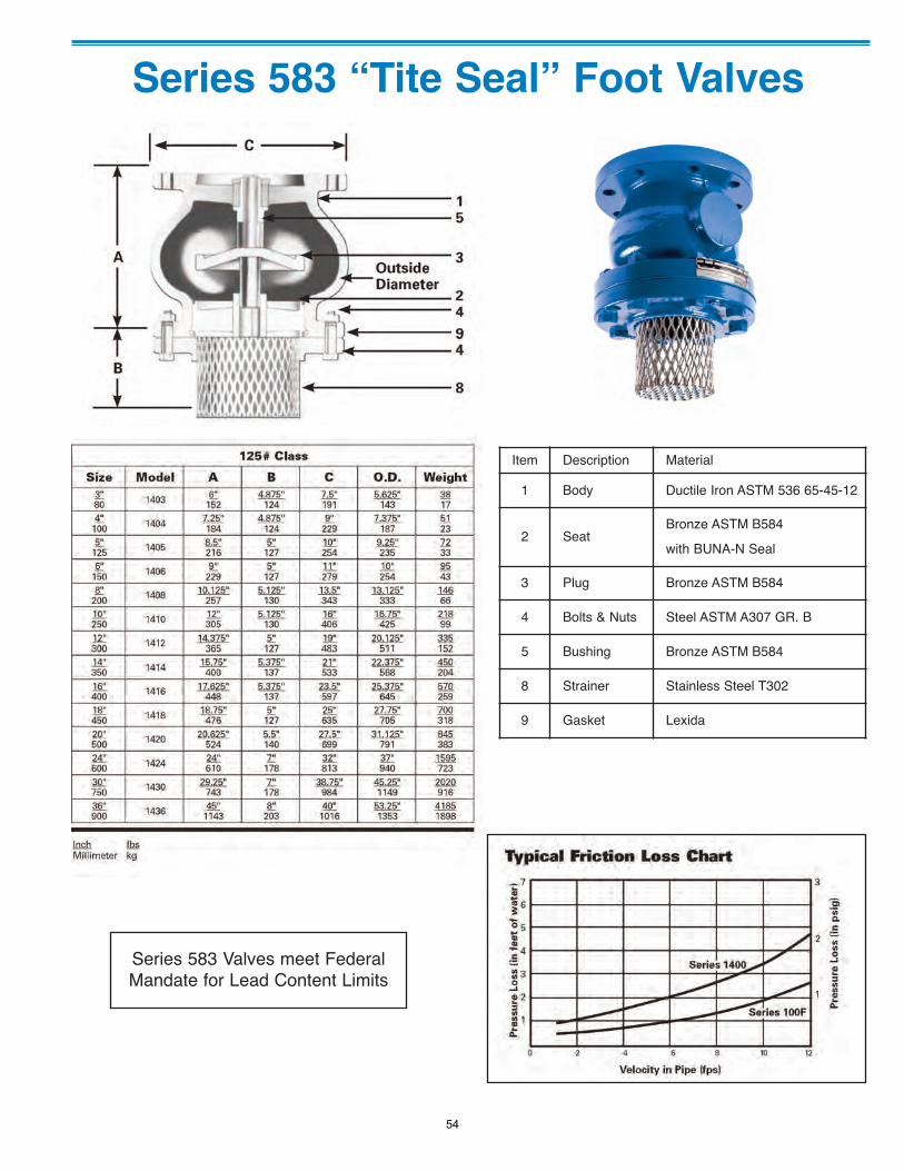
Series 583 “Tite Seal” Foot Valves
Item Description Material
1 Body Ductile Iron ASTM 536 65-45-12
2 SeatBronze ASTM B584
with BUNA-N Seal
3 Plug Bronze ASTM B584
4 Bolts & Nuts Steel ASTM A307 GR. B
5 Bushing Bronze ASTM B584
8 Strainer Stainless Steel T302
9 Gasket Lexida
Series 583 Valves meet FederalMandate for Lead Content Limits
54
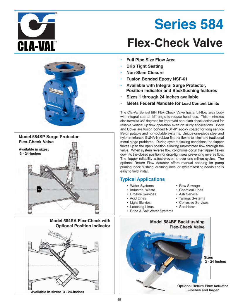
Series 584
Flex-Check Valve
The Cla-Val Seriesl 584 Flex-Check Valve has a full-flow area bodywith integral seat at 45° angle to reduce head loss. This minimizesdisc travel to 35° degrees for improved non-slam check action and forreliable vertical up flow operation even on slurry applications. Bodyand Cover are fusion bonded NSF-61 epoxy coated for long servicelife on potable and non-potable systems. Unique one-piece steel andnylon reinforced BUNA-N rubber flapper flexes to eliminate traditionalmetal hinge problems. During system flowing conditions the flapperflexes up to the open position allowing unrestricted flow through thevalve. When system reverse flow conditions occur the flapper flexesdown to the closed position for drop-tight seal preventing reverse flow.The flapper reliability is test-proven to over one million cycles. Theoptional Return Flow Actuator offers manual opening for pumppriming, back flushing, draining lines, or system testing needs and iseasy to field install.
• Full Pipe Size Flow Area
• Drip Tight Seating
• Non-Slam Closure
• Fusion Bonded Epoxy NSF-61
• Available with Integral Surge Protector,
Position Indicator and Backflushing features
• Sizes 1 through 24 inches available
• Meets Federal Mandate for Lead Content Limits
Available in sizes:
3 - 24-inches
Model 584SP Surge Protector
Flex-Check Valve
Model 584SA Flex-Check with
Optional Position IndicatorModel 584BF Backflushing
Flex-Check Valve
Typical Applications
• Water Systems • Raw Sewage• Industrial Waste • Chemical Lines• Erosive Services • Ash Service• Acid Lines • Tailings Systems• Light Slurries • Corrosive Services• Leaching Lines • Scrubbers• Brine & Salt Water Systems
Available in sizes: 3 - 24-inches
Sizes
3 - 24 inches
Optional Return Flow Actuator
3-inches and larger
55
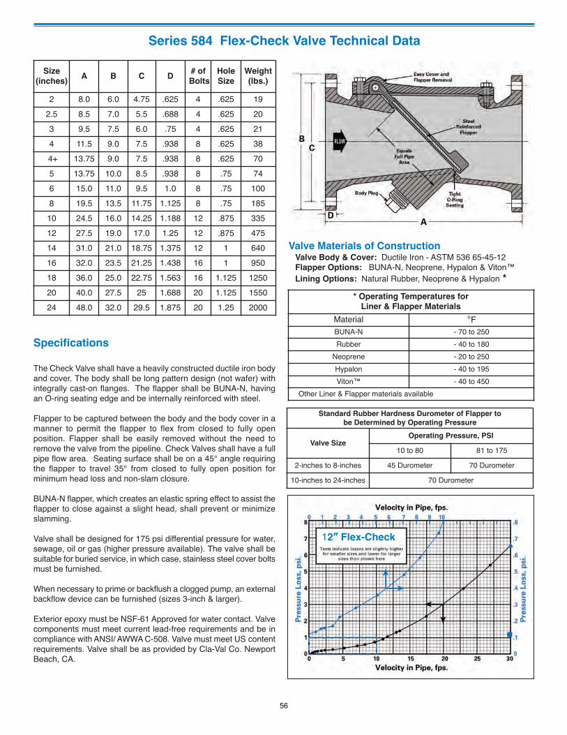
Series 584 Flex-Check Valve Technical Data
Size
(inches)A B C D
# of
Bolts
Hole
Size
Weight
(lbs.)
2 8.0 6.0 4.75 .625 4 .625 192.5 8.5 7.0 5.5 .688 4 .625 203 9.5 7.5 6.0 .75 4 .625 214 11.5 9.0 7.5 .938 8 .625 384+ 13.75 9.0 7.5 .938 8 .625 705 13.75 10.0 8.5 .938 8 .75 746 15.0 11.0 9.5 1.0 8 .75 1008 19.5 13.5 11.75 1.125 8 .75 185
10 24.5 16.0 14.25 1.188 12 .875 33512 27.5 19.0 17.0 1.25 12 .875 47514 31.0 21.0 18.75 1.375 12 1 64016 32.0 23.5 21.25 1.438 16 1 95018 36.0 25.0 22.75 1.563 16 1.125 125020 40.0 27.5 25 1.688 20 1.125 155024 48.0 32.0 29.5 1.875 20 1.25 2000
Valve Materials of ConstructionValve Body & Cover: Ductile Iron - ASTM 536 65-45-12Flapper Options: BUNA-N, Neoprene, Hypalon & Viton™Lining Options: Natural Rubber, Neoprene & Hypalon *
Standard Rubber Hardness Durometer of Flapper to
be Determined by Operating Pressure
Valve SizeOperating Pressure, PSI
10 to 80 81 to 175
2-inches to 8-inches 45 Durometer 70 Durometer
10-inches to 24-inches 70 Durometer
* Operating Temperatures for
Liner & Flapper Materials
Material °FBUNA-N - 70 to 250Rubber - 40 to 180
Neoprene - 20 to 250Hypalon - 40 to 195Viton™ - 40 to 450
Other Liner & Flapper materials available
Specifications
The Check Valve shall have a heavily constructed ductile iron bodyand cover. The body shall be long pattern design (not wafer) withintegrally cast-on flanges. The flapper shall be BUNA-N, havingan O-ring seating edge and be internally reinforced with steel.
Flapper to be captured between the body and the body cover in amanner to permit the flapper to flex from closed to fully openposition. Flapper shall be easily removed without the need toremove the valve from the pipeline. Check Valves shall have a fullpipe flow area. Seating surface shall be on a 45° angle requiringthe flapper to travel 35° from closed to fully open position forminimum head loss and non-slam closure.
BUNA-N flapper, which creates an elastic spring effect to assist theflapper to close against a slight head, shall prevent or minimizeslamming.
Valve shall be designed for 175 psi differential pressure for water,sewage, oil or gas (higher pressure available). The valve shall besuitable for buried service, in which case, stainless steel cover boltsmust be furnished.
When necessary to prime or backflush a clogged pump, an externalbackflow device can be furnished (sizes 3-inch & larger).
Exterior epoxy must be NSF-61 Approved for water contact. Valvecomponents must meet current lead-free requirements and be incompliance with ANSI/ AWWA C-508. Valve must meet US contentrequirements. Valve shall be as provided by Cla-Val Co. NewportBeach, CA.
12” Flex-Check
56
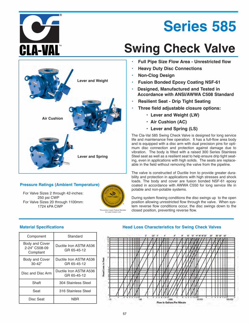
Series 585
Swing Check Valve
The Cla-Val 585 Swing Check Valve is designed for long servicelife and maintenance free operation. It has a full-flow area bodyand is equipped with a disc arm with dual precision pins for opti-mum disc connection and protection against damage due tovibration. The body is fitted with a raised 300 Series StainlessSteel seat as well as a resilient seat to help ensure drip tight seat-ing, even in applications with high solids. The seats are replace-able in the field without removing the valve from the pipeline.
The valve is constructed of Ductile Iron to provide greater dura-bility and protection in applications with high stresses and shockloads. The body and cover are fusion bonded NSF-61 epoxycoated in accordance with AWWA C550 for long service life inpotable and non-potable systems.
During system flowing conditions the disc swings up to the openposition allowing unrestricted flow through the valve. When sys-tem reverse flow conditions occur, the disc swings down to theclosed position, preventing reverse flow.
• Full Pipe Size Flow Area - Unrestricted flow
• Heavy Duty Disc Connections
• Non-Clog Design
• Fusion Bonded Epoxy Coating NSF-61
• Designed, Manufactured and Tested in
Accordance with ANSI/AWWA C508 Standard
• Resilient Seat - Drip Tight Seating
• Three field adjustable closure options:
• Lever and Weight (LW)
• Air Cushion (AC)
• Lever and Spring (LS)
Lever and Weight
Air Cushion
Lever and Spring
Head Loss Characteristics for Swing Check Valves
Pressure Ratings (Ambient Temperature)
For Valve Sizes 2 through 42-inches:250 psi CWP
For Valve Sizes 20 through 1100mm:1724 kPA CWP
Component Standard
Body and Cover2-24” C508-09
Compliant
Ductile Iron ASTM A536GR 65-45-12
Body and Cover30-42”
Ductile Iron ASTM A536GR 65-45-12
Disc and Disc Arm Ductile Iron ASTM A536GR 65-45-12
Shaft 304 Stainless Steel
Seat 316 Stainless Steel
Disc Seat NBR
Material Specifications
This product meets Federal Mandate for Lead Content Limit
57
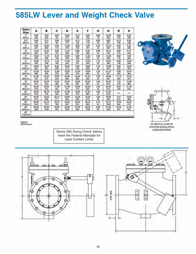
585LW Lever and Weight Check Valve
Series 585 Swing Check Valvesmeet the Federal Mandate for
Lead Content Limits
58
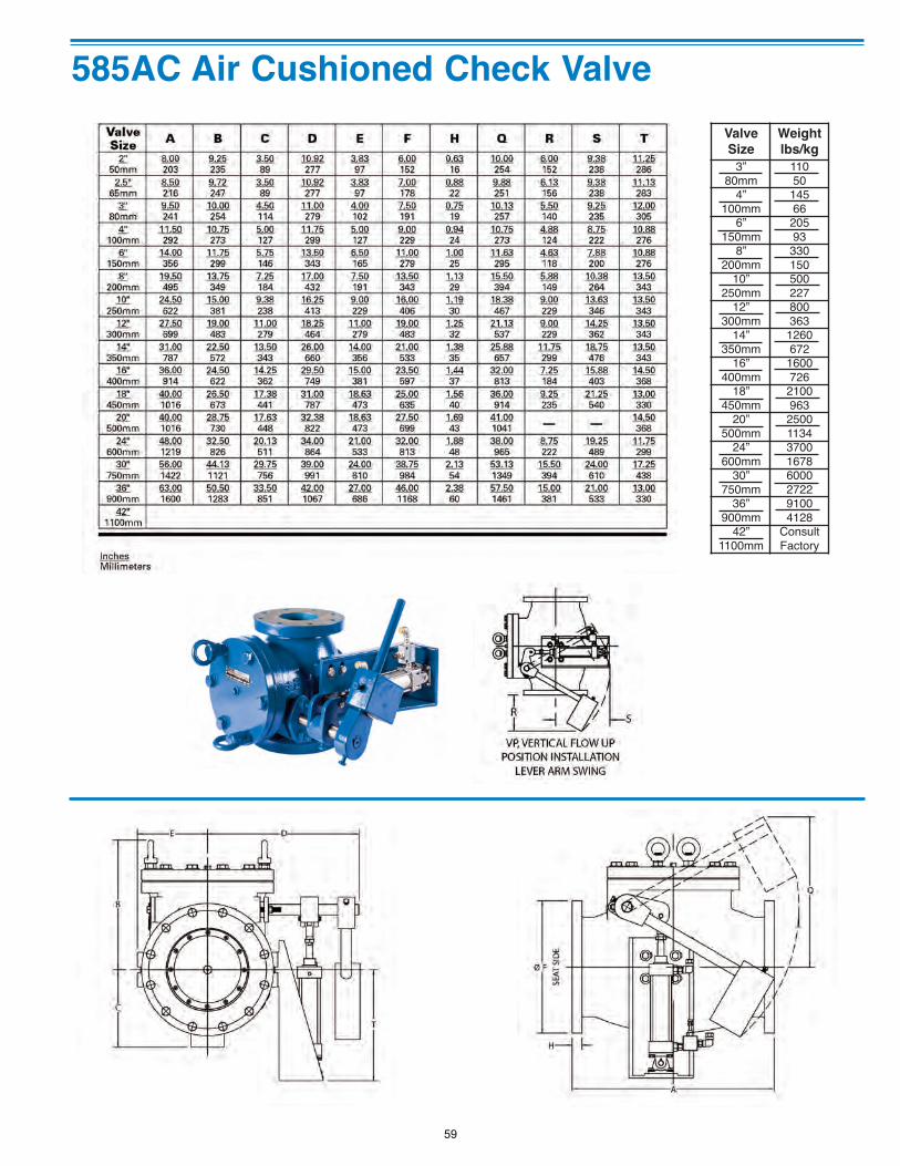
585AC Air Cushioned Check Valve ValveSize
Weightlbs/kg
3”80mm
11050
4”100mm
14566
6”150mm
20593
8”200mm
330150
10”250mm
500227
12”300mm
800363
14”350mm
1260672
16”400mm
1600726
18”450mm
2100963
20”500mm
25001134
24”600mm
37001678
30”750mm
60002722
36”900mm
91004128
42”1100mm
ConsultFactory
59
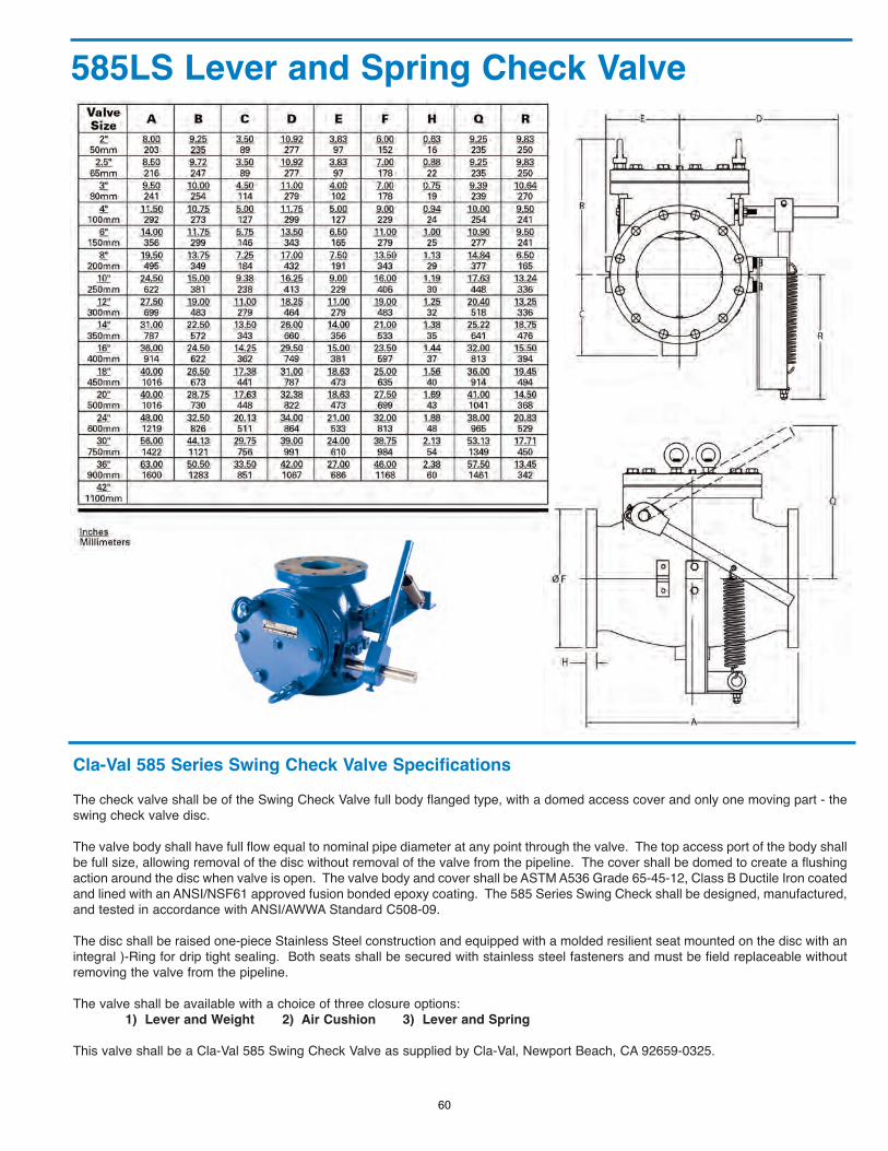
585LS Lever and Spring Check Valve
Cla-Val 585 Series Swing Check Valve SpecificationsThe check valve shall be of the Swing Check Valve full body flanged type, with a domed access cover and only one moving part - theswing check valve disc.
The valve body shall have full flow equal to nominal pipe diameter at any point through the valve. The top access port of the body shallbe full size, allowing removal of the disc without removal of the valve from the pipeline. The cover shall be domed to create a flushingaction around the disc when valve is open. The valve body and cover shall be ASTM A536 Grade 65-45-12, Class B Ductile Iron coatedand lined with an ANSI/NSF61 approved fusion bonded epoxy coating. The 585 Series Swing Check shall be designed, manufactured,and tested in accordance with ANSI/AWWA Standard C508-09.
The disc shall be raised one-piece Stainless Steel construction and equipped with a molded resilient seat mounted on the disc with anintegral )-Ring for drip tight sealing. Both seats shall be secured with stainless steel fasteners and must be field replaceable withoutremoving the valve from the pipeline.
The valve shall be available with a choice of three closure options:1) Lever and Weight 2) Air Cushion 3) Lever and Spring
This valve shall be a Cla-Val 585 Swing Check Valve as supplied by Cla-Val, Newport Beach, CA 92659-0325.
60
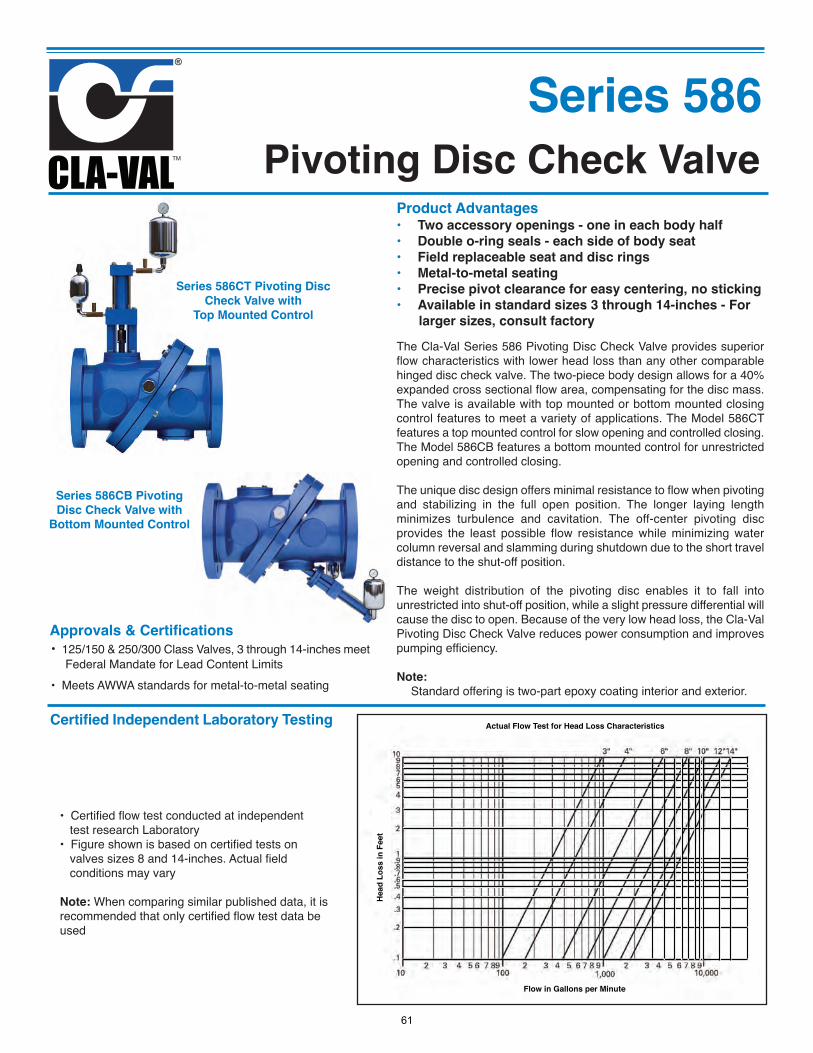
Pivoting Disc Check Valve
Series 586
Product Advantages• Two accessory openings - one in each body half
• Double o-ring seals - each side of body seat
• Field replaceable seat and disc rings
• Metal-to-metal seating
• Precise pivot clearance for easy centering, no sticking
• Available in standard sizes 3 through 14-inches - For
larger sizes, consult factory
Actual Flow Test for Head Loss Characteristics
Flow in Gallons per Minute
Head
Los
s in
Fee
t
Series 586CT Pivoting Disc
Check Valve with
Top Mounted Control
The Cla-Val Series 586 Pivoting Disc Check Valve provides superiorflow characteristics with lower head loss than any other comparablehinged disc check valve. The two-piece body design allows for a 40%expanded cross sectional flow area, compensating for the disc mass.The valve is available with top mounted or bottom mounted closingcontrol features to meet a variety of applications. The Model 586CTfeatures a top mounted control for slow opening and controlled closing.The Model 586CB features a bottom mounted control for unrestrictedopening and controlled closing.
The unique disc design offers minimal resistance to flow when pivotingand stabilizing in the full open position. The longer laying lengthminimizes turbulence and cavitation. The off-center pivoting discprovides the least possible flow resistance while minimizing watercolumn reversal and slamming during shutdown due to the short traveldistance to the shut-off position.
The weight distribution of the pivoting disc enables it to fall intounrestricted into shut-off position, while a slight pressure differential willcause the disc to open. Because of the very low head loss, the Cla-ValPivoting Disc Check Valve reduces power consumption and improvespumping efficiency.
Note:
Standard offering is two-part epoxy coating interior and exterior.
Approvals & Certifications
• 125/150 & 250/300 Class Valves, 3 through 14-inches meetFederal Mandate for Lead Content Limits
• Meets AWWA standards for metal-to-metal seating
Series 586CB Pivoting
Disc Check Valve with
Bottom Mounted Control
Certified Independent Laboratory Testing
• Certified flow test conducted at independenttest research Laboratory
• Figure shown is based on certified tests onvalves sizes 8 and 14-inches. Actual fieldconditions may vary
Note: When comparing similar published data, it isrecommended that only certified flow test data beused
61
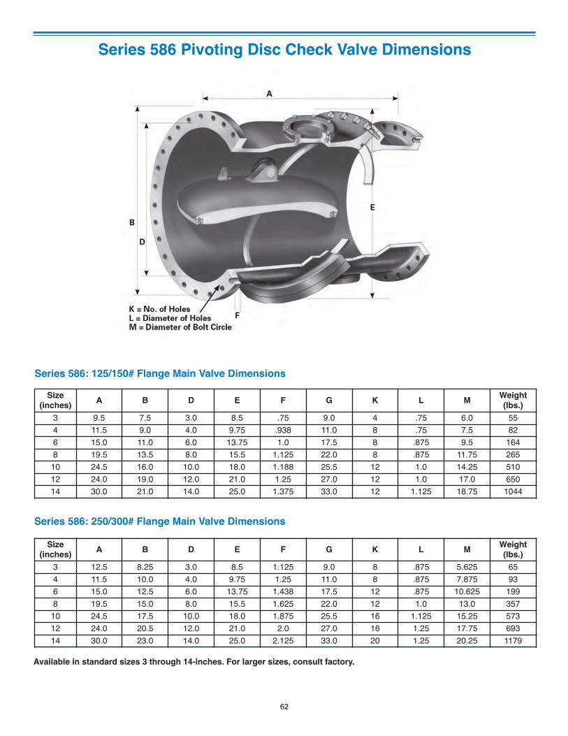
Series 586 Pivoting Disc Check Valve Dimensions
Size(inches) A B D E F G K L M Weight
(lbs.)3 9.5 7.5 3.0 8.5 .75 9.0 4 .75 6.0 554 11.5 9.0 4.0 9.75 .938 11.0 8 .75 7.5 826 15.0 11.0 6.0 13.75 1.0 17.5 8 .875 9.5 1648 19.5 13.5 8.0 15.5 1.125 22.0 8 .875 11.75 265
10 24.5 16.0 10.0 18.0 1.188 25.5 12 1.0 14.25 51012 24.0 19.0 12.0 21.0 1.25 27.0 12 1.0 17.0 65014 30.0 21.0 14.0 25.0 1.375 33.0 12 1.125 18.75 1044
Series 586: 125/150# Flange Main Valve Dimensions
Series 586: 250/300# Flange Main Valve Dimensions
Size(inches) A B D E F G K L M Weight
(lbs.)3 12.5 8.25 3.0 8.5 1.125 9.0 8 .875 5.625 654 11.5 10.0 4.0 9.75 1.25 11.0 8 .875 7.875 936 15.0 12.5 6.0 13.75 1.438 17.5 12 .875 10.625 1998 19.5 15.0 8.0 15.5 1.625 22.0 12 1.0 13.0 357
10 24.5 17.5 10.0 18.0 1.875 25.5 16 1.125 15.25 57312 24.0 20.5 12.0 21.0 2.0 27.0 16 1.25 17.75 69314 30.0 23.0 14.0 25.0 2.125 33.0 20 1.25 20.25 1179
Available in standard sizes 3 through 14-inches. For larger sizes, consult factory.
62
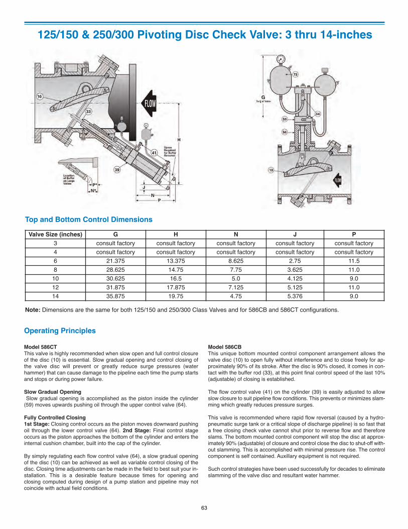
125/150 & 250/300 Pivoting Disc Check Valve: 3 thru 14-inches
Valve Size (inches) G H N J P
3 consult factory consult factory consult factory consult factory consult factory4 consult factory consult factory consult factory consult factory consult factory6 21.375 13.375 8.625 2.75 11.58 28.625 14.75 7.75 3.625 11.0
10 30.625 16.5 5.0 4.125 9.012 31.875 17.875 7.125 5.125 11.014 35.875 19.75 4.75 5.376 9.0
Note: Dimensions are the same for both 125/150 and 250/300 Class Valves and for 586CB and 586CT configurations.
Top and Bottom Control Dimensions
Operating Principles
Model 586CT
This valve is highly recommended when slow open and full control closureof the disc (10) is essential. Slow gradual opening and control closing ofthe valve disc will prevent or greatly reduce surge pressures (waterhammer) that can cause damage to the pipeline each time the pump startsand stops or during power failure.
Slow Gradual Opening
Slow gradual opening is accomplished as the piston inside the cylinder(59) moves upwards pushing oil through the upper control valve (64).
Fully Controlled Closing
1st Stage: Closing control occurs as the piston moves downward pushingoil through the lower control valve (64). 2nd Stage: Final control stageoccurs as the piston approaches the bottom of the cylinder and enters theinternal cushion chamber, built into the cap of the cylinder.
By simply regulating each flow control valve (64), a slow gradual openingof the disc (10) can be achieved as well as variable control closing of thedisc. Closing time adjustments can be made in the field to best suit your in-stallation. This is a desirable feature because times for opening andclosing computed during design of a pump station and pipeline may notcoincide with actual field conditions.
Model 586CB
This unique bottom mounted control component arrangement allows thevalve disc (10) to open fully without interference and to close freely for ap-proximately 90% of its stroke. After the disc is 90% closed, it comes in con-tact with the buffer rod (33), at this point final control speed of the last 10%(adjustable) of closing is established.
The flow control valve (41) on the cylinder (39) is easily adjusted to allowslow closure to suit pipeline flow conditions. This prevents or minimizes slam-ming which greatly reduces pressure surges.
This valve is recommended where rapid flow reversal (caused by a hydro-pneumatic surge tank or a critical slope of discharge pipeline) is so fast thata free closing check valve cannot shut prior to reverse flow and thereforeslams. The bottom mounted control component will stop the disc at approx-imately 90% (adjustable) of closure and control close the disc to shut-off with-out slamming. This is accomplished with minimal pressure rise. The controlcomponent is self contained. Auxillary equipment is not required.
Such control strategies have been used successfully for decades to eliminateslamming of the valve disc and resultant water hammer.
63
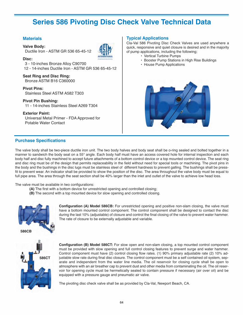
Series 586 Pivoting Disc Check Valve Technical Data
Typical ApplicationsCla-Val 586 Pivoting Disc Check Valves are used anywhere aquick, responsive and quiet closure is desired and in the majorityof pump applications, including the following;
• Vertical Turbine Pumps• Booster Pump Stations in High Rise Buildings• House Pump Applications
Materials
Valve Body:
Ductile Iron - ASTM GR 536 65-45-12
Disc:
3 - 10-inches Bronze Alloy C9070012 - 14-inches Ductile Iron - ASTM GR 536 65-45-12
Seat Ring and Disc Ring:
Bronze ASTM B16 C360000
Pivot Pins:
Stainless Steel ASTM A582 T303
Pivot Pin Bushing:
11 - 14-inches Stainless Steel A269 T304
Exterior Paint:
Universal Metal Primer - FDA Approved for Potable Water Contact
Purchase Specifications
The valve body shall be two-piece ductile iron unit. The two body halves and body seat shall be o-ring sealed and bolted together in amanner to sandwich the body seat on a 55° angle. Each body half must have an access covered hole for internal inspection and eachbody half and disc fully machined to accept future attachments of a bottom control device or a top mounted control device. The seat ringand disc ring must be of the design that permits replaceability in the field without need for special tools or machining. The pivot pins inthe body and the bushings in the disc lugs must be stainless steel of different hardness to prevent galling. The bushings shall be press-fit to prevent wear. An indicator shall be provided to show the position of the disc. The area throughout the valve body must be equal tofull pipe area. The area through the seat section shall be 40% larger than the inlet and outlet of the valve to achieve low head loss.
The valve must be available in two configurations: (A) The first with a bottom device for unrestricted opening and controlled closing; (B) The second with a top mounted device for slow opening and controlled closing.
Configuration (A) Model 586CB: For unrestricted opening and positive non-slam closing, the valve musthave a bottom mounted control component. The control component shall be designed to contact the discduring the last 10% (adjustable) of closure and control the final closing of the valve to prevent water hammer.The rate of closure to be externally adjustable and variable.
Configuration (B) Model 586CT: For slow open and non-slam closing, a top mounted control componentmust be provided with slow opening and full control closing features to prevent surge and water hammer.Control component must have (2) control closing flow rates. (1) 90% primary adjustable rate (2) 10% ad-justable slow rate during final disc closure. The control component must be a self contained oil system, sep-arate and independent from the water line media. The oil reservoir for closing cycle shall be open toatmosphere with an air breather cap to prevent dust and other media from contaminating the oil. The oil reser-voir for opening cycle must be hermetically sealed to contain pressure if necessary (air over oil) and beequipped with a pressure gauge and pneumatic air valve.
The pivoting disc check valve shall be as provided by Cla-Val, Newport Beach, CA.
586CB
586CT
64
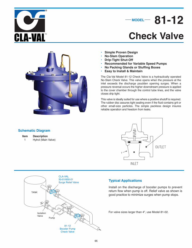
• Simple Proven Design• No-Slam Operation• Drip-Tight Shut-Off• Recommended for Variable Speed Pumps• No Packing Glands or Stuffing Boxes• Easy to Install & Maintain
The Cla-Val Model 81-12 Check Valve is a hydraulically operated No-Slam Check Valve. This valve opens when the pressure at theinlet exceeds the discharge psudden opening surges. When a pressure reversal occurs the higher downstream pressure is appliedto the cover chamber through the control tube lines, and the valvecloses drip tight.
This valve is ideally suited for use where a positive shutoff is required.The rubber disc assures tight sealing even if the fluid contains grit orother small-size particles. The simple packless design insures reliable operation and freedom from leaks.
Schematic Diagram
Item Description1 Hytrol (Main Valve)
Typical Applications
Check Valve
For valve sizes larger than 4", use Model 81-02.
MODEL
Install on the discharge of booster pumps to prevent return flow when pump is off. Relief valve as shown isgood practice to minimize surges when pump stops.
81-12
65
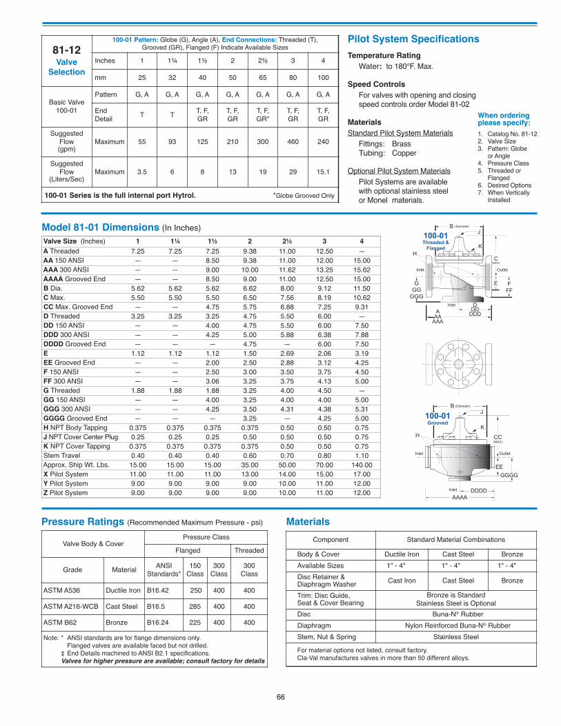
Temperature RatingWater: to 180°F. Max.
Speed ControlsFor valves with opening and closingspeed controls order Model 81-02
MaterialsStandard Pilot System Materials
Fittings: BrassTubing: Copper
Optional Pilot System MaterialsPilot Systems are available with optional stainless steel or Monel materials.
Pilot System Specifications
1. Catalog No. 81-122. Valve Size3. Pattern: Globe
or Angle4. Pressure Class5. Threaded or
Flanged6. Desired Options7. When Vertically
Installed
When ordering please specify:
81-12Valve
Selection
100-01 Pattern: Globe (G), Angle (A), End Connections: Threaded (T), Grooved (GR), Flanged (F) Indicate Available Sizes
Inches 1 1¼ 1½ 2 2½ 3 4
mm 25 32 40 50 65 80 100
Basic Valve100-01
Pattern G, A G, A G, A G, A G, A G, A G, A
End Detail
T TT, F,GR
T, F,GR
T, F,GR*
T, F,GR
T, F,GR
Suggested Flow (gpm)
Maximum 55 93 125 210 300 460 240
Suggested Flow
(Liters/Sec)Maximum 3.5 6 8 13 19 29 15.1
100-01 Series is the full internal port Hytrol. *Globe Grooved Only
Model 81-01 Dimensions (In Inches)
Valve Size (Inches) 1 1¼ 1½ 2 2½ 3 4A Threaded 7.25 7.25 7.25 9.38 11.00 12.50 —AA 150 ANSI — — 8.50 9.38 11.00 12.00 15.00AAA 300 ANSI — — 9.00 10.00 11.62 13.25 15.62AAAA Grooved End — — 8.50 9.00 11.00 12.50 15.00B Dia. 5.62 5.62 5.62 6.62 8.00 9.12 11.50C Max. 5.50 5.50 5.50 6.50 7.56 8.19 10.62CC Max. Grooved End — — 4.75 5.75 6.88 7.25 9.31D Threaded 3.25 3.25 3.25 4.75 5.50 6.00 —DD 150 ANSI — — 4.00 4.75 5.50 6.00 7.50DDD 300 ANSI — — 4.25 5.00 5.88 6.38 7.88DDDD Grooved End — — — 4.75 — 6.00 7.50E 1.12 1.12 1.12 1.50 2.69 2.06 3.19EE Grooved End — — 2.00 2.50 2.88 3.12 4.25F 150 ANSI — — 2.50 3.00 3.50 3.75 4.50FF 300 ANSI — — 3.06 3.25 3.75 4.13 5.00G Threaded 1.88 1.88 1.88 3.25 4.00 4.50 —GG 150 ANSI — — 4.00 3.25 4.00 4.00 5.00GGG 300 ANSI — — 4.25 3.50 4.31 4.38 5.31GGGG Grooved End — — — 3.25 — 4.25 5.00H NPT Body Tapping 0.375 0.375 0.375 0.375 0.50 0.50 0.75J NPT Cover Center Plug 0.25 0.25 0.25 0.50 0.50 0.50 0.75K NPT Cover Tapping 0.375 0.375 0.375 0.375 0.50 0.50 0.75Stem Travel 0.40 0.40 0.40 0.60 0.70 0.80 1.10Approx. Ship Wt. Lbs. 15.00 15.00 15.00 35.00 50.00 70.00 140.00X Pilot System 11.00 11.00 11.00 13.00 14.00 15.00 17.00Y Pilot System 9.00 9.00 9.00 9.00 10.00 11.00 12.00Z Pilot System 9.00 9.00 9.00 9.00 10.00 11.00 12.00
Component Standard Material Combinations
Body & Cover Ductile Iron Cast Steel Bronze
Available Sizes 1" - 4" 1" - 4" 1" - 4"
Disc Retainer &Diaphragm Washer Cast Iron Cast Steel Bronze
Trim: Disc Guide, Seat & Cover Bearing
Bronze is StandardStainless Steel is Optional
Disc Buna-N® Rubber
Diaphragm Nylon Reinforced Buna-N® Rubber
Stem, Nut & Spring Stainless Steel
For material options not listed, consult factory.Cla-Val manufactures valves in more than 50 different alloys.
Valve Body & CoverPressure Class
Flanged Threaded
Grade MaterialANSI
Standards*150
Class 300
Class300
Class
ASTM A536 Ductile Iron B16.42 250 400 400
ASTM A216-WCB Cast Steel B16.5 285 400 400
ASTM B62 Bronze B16.24 225 400 400
Note: * ANSI standards are for flange dimensions only.Flanged valves are available faced but not drilled.
‡ End Details machined to ANSI B2.1 specifications.Valves for higher pressure are available; consult factory for details
Pressure Ratings (Recommended Maximum Pressure - psi) Materials
GGG
GGGDInlet
DDDDD
FFF
100-01Threaded &
Flanged
A
E
C(MAX)
K
J
H
Inlet Outlet
AAAAA
B (Diameter)
GGGG
DDDDInlet
AAAA
100-01Grooved
EE
CC(MAX)
K
J
H
Inlet Outlet
B (Diameter)
66
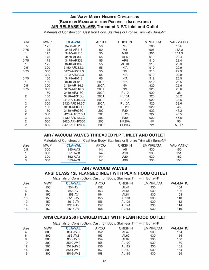
AIR VALVE MODEL NUMBER COMPARISON(BASED ON MANUFACTURERS PUBLISHED INFORMATION)
AIR RELEASE VALVES Threaded N.P.T. Inlet and OutletMaterials of Construction: Cast Iron Body, Stainless or Bronze Trim with Buna-N®
Size MWP CLA-VAL APCO CRISPIN EMPIRE/GA VAL-MATIC 0.5 175 3450-AR116 50 M5 905 15A
0.75 175 3475-AR116 50 M8 905 15A.21 175 3410-AR116 50 M10 905 15A.3
0.5 175 3450-AR332 55 AR5 910 22.40.75 175 3475-AR332 55 AR8 910 22.4
1 175 3410-AR332 55 AR10 910 22.30.5 300 3450-AR332.3 55 N/A 910 22.90.75 300 3475-AR332.3 55 NM 910 22.9
1 300 3410-AR332.3 55 N/A 910 22.90.75 150 3475-AR018 65 N/A 912 25.5
1 150 3410-AR018 200A N/A 912 25.50.5 300 3450-AR116.3 200A NM 920 25.60.75 300 3475-AR116.3 200A NM 920 25.6
1 150 3410-AR316C 200A PL10 920 382 150 3420-AR316C 200A PL10A 920 38.21 300 3410-AR316.3C 200A PL10 920 38.52 300 3420-AR316.3C 200A PL10A 920 38.62 150 3420-AR038C 200 PL20 922 453 150 3430-AR038C 200 P30 922 45.22 300 3420-AR732.3C 200 PL20 922 45.53 300 3430-AR732.3C 200 P30 922 45.62 500 3420-AR-HP500 205 HP20A NM 502 800 3420-AR-HP800 206 HP20C NM 50HP
AIR / VACUUM VALVES THREADED N.P.T. INLET AND OUTLETMaterials of Construction: Cast Iron Body, Stainless or Bronze Trim with Buna-N®
Size MWP CLA-VAL APCO CRISPIN EMPIRE/GA VAL-MATIC0.5 300 350-AV.3 141 A5 930 150 1 300 351-AV.3 142 A10 930 1512 300 352-AV.3 144 A20 930 1523 300 353-AV.3 146 A30 930 153
AIR / VACUUM VALVESANSI CLASS 125 FLANGED INLET WITH PLAIN HOOD OUTLET
Materials of Construction: Cast Iron Body, Stainless Trim with Buna-N®
Size MWP CLA-VAL APCO CRISPIN EMPIRE/GA VAL-MATIC4 150 354-AV 152 AL41 930 1046 150 356-AV 153 AL61 930 1068 150 358-AV 154 AL81 930 108
10 150 3510-AV 155 AL101 930 110 12 150 3612-AV 156 AL121 930 112 14 150 3S14-AV 157 AL141 930 114 16 150 3516-AV 158 AL161 930 116
ANSI CLASS 250 FLANGED INLET WITH PLAIN HOOD OUTLETMaterials of Construction: Cast Iron Body, Stainless Trim with Buna-N®
Size MWP CLA-VAL APCO CRISPIN EMPIRE/GA VAL-MATIC4 300 354-AV.3 152 AL42 930 1546 300 356-AV.3 153 AL62 930 1568 300 358-AV.3 154 AL82 930 158
10 300 3510-AV.3 155 AL102 930 160 12 300 3512-AV.3 156 AL122 930 162 14 300 3514-AV.3 157 AL142 930 164 16 300 3516-AV.3 158 AL162 930 166
67
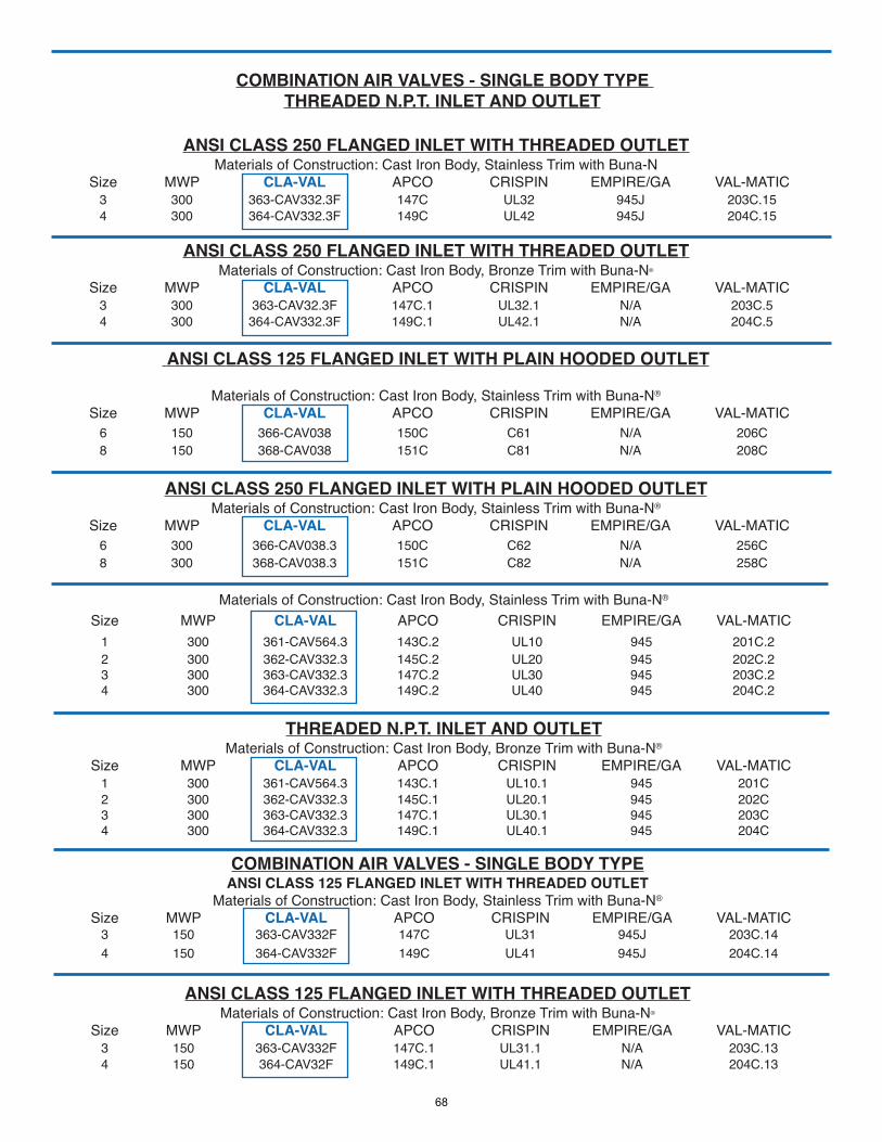
ANSI CLASS 250 FLANGED INLET WITH THREADED OUTLETMaterials of Construction: Cast Iron Body, Stainless Trim with Buna-N
Size MWP CLA-VAL APCO CRISPIN EMPIRE/GA VAL-MATIC3 300 363-CAV332.3F 147C UL32 945J 203C.154 300 364-CAV332.3F 149C UL42 945J 204C.15
ANSI CLASS 250 FLANGED INLET WITH THREADED OUTLETMaterials of Construction: Cast Iron Body, Bronze Trim with Buna-N®
Size MWP CLA-VAL APCO CRISPIN EMPIRE/GA VAL-MATIC3 300 363-CAV32.3F 147C.1 UL32.1 N/A 203C.54 300 364-CAV332.3F 149C.1 UL42.1 N/A 204C.5
ANSI CLASS 125 FLANGED INLET WITH PLAIN HOODED OUTLET
Materials of Construction: Cast Iron Body, Stainless Trim with Buna-N®
Size MWP CLA-VAL APCO CRISPIN EMPIRE/GA VAL-MATIC6 150 366-CAV038 150C C61 N/A 206C8 150 368-CAV038 151C C81 N/A 208C
ANSI CLASS 250 FLANGED INLET WITH PLAIN HOODED OUTLETMaterials of Construction: Cast Iron Body, Stainless Trim with Buna-N®
Size MWP CLA-VAL APCO CRISPIN EMPIRE/GA VAL-MATIC6 300 366-CAV038.3 150C C62 N/A 256C8 300 368-CAV038.3 151C C82 N/A 258C
COMBINATION AIR VALVES - SINGLE BODY TYPETHREADED N.P.T. INLET AND OUTLET
Materials of Construction: Cast Iron Body, Stainless Trim with Buna-N®
Size MWP CLA-VAL APCO CRISPIN EMPIRE/GA VAL-MATIC1 300 361-CAV564.3 143C.2 UL10 945 201C.22 300 362-CAV332.3 145C.2 UL20 945 202C.23 300 363-CAV332.3 147C.2 UL30 945 203C.24 300 364-CAV332.3 149C.2 UL40 945 204C.2
THREADED N.P.T. INLET AND OUTLETMaterials of Construction: Cast Iron Body, Bronze Trim with Buna-N®
Size MWP CLA-VAL APCO CRISPIN EMPIRE/GA VAL-MATIC1 300 361-CAV564.3 143C.1 UL10.1 945 201C2 300 362-CAV332.3 145C.1 UL20.1 945 202C3 300 363-CAV332.3 147C.1 UL30.1 945 203C4 300 364-CAV332.3 149C.1 UL40.1 945 204C
COMBINATION AIR VALVES - SINGLE BODY TYPEANSI CLASS 125 FLANGED INLET WITH THREADED OUTLET
Materials of Construction: Cast Iron Body, Stainless Trim with Buna-N®
Size MWP CLA-VAL APCO CRISPIN EMPIRE/GA VAL-MATIC3 150 363-CAV332F 147C UL31 945J 203C.144 150 364-CAV332F 149C UL41 945J 204C.14
ANSI CLASS 125 FLANGED INLET WITH THREADED OUTLETMaterials of Construction: Cast Iron Body, Bronze Trim with Buna-N®
Size MWP CLA-VAL APCO CRISPIN EMPIRE/GA VAL-MATIC3 150 363-CAV332F 147C.1 UL31.1 N/A 203C.134 150 364-CAV32F 149C.1 UL41.1 N/A 204C.13
68
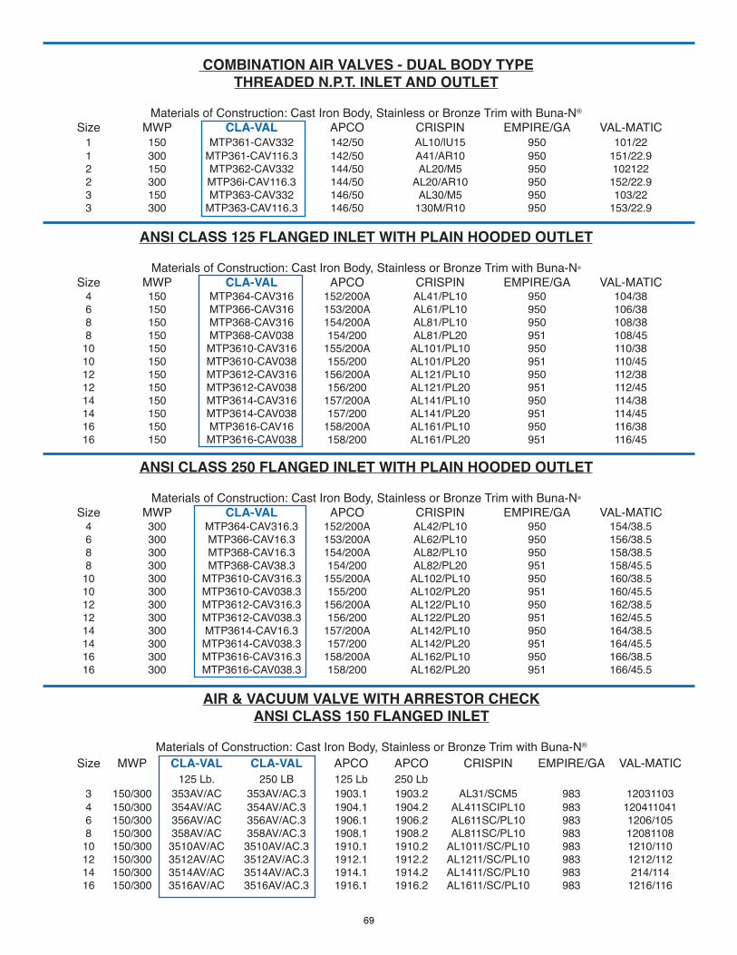
COMBINATION AIR VALVES - DUAL BODY TYPETHREADED N.P.T. INLET AND OUTLET
Materials of Construction: Cast Iron Body, Stainless or Bronze Trim with Buna-N®
Size MWP CLA-VAL APCO CRISPIN EMPIRE/GA VAL-MATIC1 150 MTP361-CAV332 142/50 AL10/lU15 950 101/221 300 MTP361-CAV116.3 142/50 A41/AR10 950 151/22.92 150 MTP362-CAV332 144/50 AL20/M5 950 1021222 300 MTP36i-CAV116.3 144/50 AL20/AR10 950 152/22.93 150 MTP363-CAV332 146/50 AL30/M5 950 103/223 300 MTP363-CAV116.3 146/50 130M/R10 950 153/22.9
ANSI CLASS 125 FLANGED INLET WITH PLAIN HOODED OUTLET
Materials of Construction: Cast Iron Body, Stainless or Bronze Trim with Buna-N®
Size MWP CLA-VAL APCO CRISPIN EMPIRE/GA VAL-MATIC4 150 MTP364-CAV316 152/200A AL41/PL10 950 104/386 150 MTP366-CAV316 153/200A AL61/PL10 950 106/388 150 MTP368-CAV316 154/200A AL81/PL10 950 108/388 150 MTP368-CAV038 154/200 AL81/PL20 951 108/45
10 150 MTP3610-CAV316 155/200A AL101/PL10 950 110/3810 150 MTP3610-CAV038 155/200 AL101/PL20 951 110/4512 150 MTP3612-CAV316 156/200A AL121/PL10 950 112/3812 150 MTP3612-CAV038 156/200 AL121/PL20 951 112/4514 150 MTP3614-CAV316 157/200A AL141/PL10 950 114/3814 150 MTP3614-CAV038 157/200 AL141/PL20 951 114/4516 150 MTP3616-CAV16 158/200A AL161/PL10 950 116/3816 150 MTP3616-CAV038 158/200 AL161/PL20 951 116/45
ANSI CLASS 250 FLANGED INLET WITH PLAIN HOODED OUTLET
Materials of Construction: Cast Iron Body, Stainless or Bronze Trim with Buna-N®
Size MWP CLA-VAL APCO CRISPIN EMPIRE/GA VAL-MATIC4 300 MTP364-CAV316.3 152/200A AL42/PL10 950 154/38.56 300 MTP366-CAV16.3 153/200A AL62/PL10 950 156/38.58 300 MTP368-CAV16.3 154/200A AL82/PL10 950 158/38.58 300 MTP368-CAV38.3 154/200 AL82/PL20 951 158/45.5
10 300 MTP3610-CAV316.3 155/200A AL102/PL10 950 160/38.510 300 MTP3610-CAV038.3 155/200 AL102/PL20 951 160/45.5 12 300 MTP3612-CAV316.3 156/200A AL122/PL10 950 162/38.512 300 MTP3612-CAV038.3 156/200 AL122/PL20 951 162/45.514 300 MTP3614-CAV16.3 157/200A AL142/PL10 950 164/38.514 300 MTP3614-CAV038.3 157/200 AL142/PL20 951 164/45.516 300 MTP3616-CAV316.3 158/200A AL162/PL10 950 166/38.516 300 MTP3616-CAV038.3 158/200 AL162/PL20 951 166/45.5
AIR & VACUUM VALVE WITH ARRESTOR CHECKANSI CLASS 150 FLANGED INLET
Materials of Construction: Cast Iron Body, Stainless or Bronze Trim with Buna-N®
Size MWP CLA-VAL CLA-VAL APCO APCO CRISPIN EMPIRE/GA VAL-MATIC125 Lb. 250 LB 125 Lb 250 Lb
3 150/300 353AV/AC 353AV/AC.3 1903.1 1903.2 AL31/SCM5 983 120311034 150/300 354AV/AC 354AV/AC.3 1904.1 1904.2 AL411SCIPL10 983 1204110416 150/300 356AV/AC 356AV/AC.3 1906.1 1906.2 AL611SC/PL10 983 1206/1058 150/300 358AV/AC 358AV/AC.3 1908.1 1908.2 AL811SC/PL10 983 12081108
10 150/300 3510AV/AC 3510AV/AC.3 1910.1 1910.2 AL1011/SC/PL10 983 1210/110 12 150/300 3512AV/AC 3512AV/AC.3 1912.1 1912.2 AL1211/SC/PL10 983 1212/112 14 150/300 3514AV/AC 3514AV/AC.3 1914.1 1914.2 AL1411/SC/PL10 983 214/114 16 150/300 3516AV/AC 3516AV/AC.3 1916.1 1916.2 AL1611/SC/PL10 983 1216/116
69
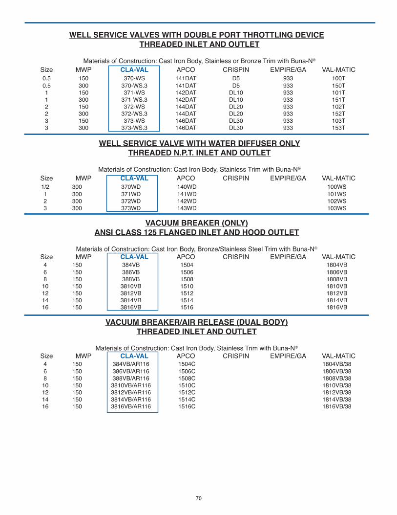
WELL SERVICE VALVES WITH DOUBLE PORT THROTTLING DEVICETHREADED INLET AND OUTLET
Materials of Construction: Cast Iron Body, Stainless or Bronze Trim with Buna-N®
Size MWP CLA-VAL APCO CRISPIN EMPIRE/GA VAL-MATIC 0.5 150 370-WS 141DAT D5 933 100T 0.5 300 370-WS.3 141DAT D5 933 150T
1 150 371-WS 142DAT DL10 933 101T1 300 371-WS.3 142DAT DL10 933 151T2 150 372-WS 144DAT DL20 933 102T2 300 372-WS.3 144DAT DL20 933 152T3 150 373-WS 146DAT DL30 933 103T3 300 373-WS.3 146DAT DL30 933 153T
WELL SERVICE VALVE WITH WATER DIFFUSER ONLYTHREADED N.P.T. INLET AND OUTLET
Materials of Construction: Cast Iron Body, Stainless Trim with Buna-N®
Size MWP CLA-VAL APCO CRISPIN EMPIRE/GA VAL-MATIC1/2 300 370WD 140WD 100WS1 300 371WD 141WD 101WS2 300 372WD 142WD 102WS3 300 373WD 143WD 103WS
VACUUM BREAKER (ONLY)ANSI CLASS 125 FLANGED INLET AND HOOD OUTLET
Materials of Construction: Cast Iron Body, Bronze/Stainless Steel Trim with Buna-N®
Size MWP CLA-VAL APCO CRISPIN EMPIRE/GA VAL-MATIC4 150 384VB 1504 1804VB6 150 386VB 1506 1806VB 8 150 388VB 1508 1808VB
10 150 3810VB 1510 1810VB12 150 3812VB 1512 1812VB14 150 3814VB 1514 1814VB16 150 3816VB 1516 1816VB
VACUUM BREAKER/AIR RELEASE (DUAL BODY)THREADED INLET AND OUTLET
Materials of Construction: Cast Iron Body, Stainless Trim with Buna-N®
Size MWP CLA-VAL APCO CRISPIN EMPIRE/GA VAL-MATIC4 150 384VB/AR116 1504C 1804VB/386 150 386VB/AR116 1506C 1806VB/388 150 388VB/AR116 1508C 1808VB/3810 150 3810VB/AR116 1510C 1810VB/3812 150 3812VB/AR116 1512C 1812VB/3814 150 3814VB/AR116 1514C 1814VB/3816 150 3816VB/AR116 1516C 1816VB/38
70
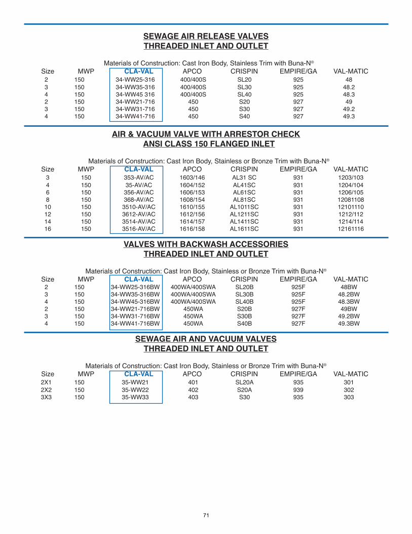
SEWAGE AIR RELEASE VALVESTHREADED INLET AND OUTLET
Materials of Construction: Cast Iron Body, Stainless Trim with Buna-N®
Size MWP CLA-VAL APCO CRISPIN EMPIRE/GA VAL-MATIC2 150 34-WW25-316 400/400S SL20 925 483 150 34-WW35-316 400/400S SL30 925 48.24 150 34-WW45 316 400/400S SL40 925 48.32 150 34-WW21-716 450 S20 927 493 150 34-WW31-716 450 S30 927 49.24 150 34-WW41-716 450 S40 927 49.3
AIR & VACUUM VALVE WITH ARRESTOR CHECKANSI CLASS 150 FLANGED INLET
Materials of Construction: Cast Iron Body, Stainless or Bronze Trim with Buna-N®
Size MWP CLA-VAL APCO CRISPIN EMPIRE/GA VAL-MATIC3 150 353-AV/AC 1603/146 AL31 SC 931 1203/1034 150 35-AV/AC 1604/152 AL41SC 931 1204/1046 150 356-AV/AC 1606/153 AL61SC 931 1206/1058 150 368-AV/AC 1608/154 AL81SC 931 12081108
10 150 3510-AV/AC 1610/155 AL1011SC 931 12101110 12 150 3612-AV/AC 1612/156 AL1211SC 931 1212/112 14 150 3514-AV/AC 1614/157 AL1411SC 931 1214/114 16 150 3516-AV/AC 1616/158 AL1611SC 931 12161116
VALVES WITH BACKWASH ACCESSORIESTHREADED INLET AND OUTLET
Materials of Construction: Cast Iron Body, Stainless or Bronze Trim with Buna-N®
Size MWP CLA-VAL APCO CRISPIN EMPIRE/GA VAL-MATIC2 150 34-WW25-316BW 400WA/400SWA SL20B 925F 48BW3 150 34-WW35-316BW 400WA/400SWA SL30B 925F 48.2BW4 150 34-WW45-316BW 400WA/400SWA SL40B 925F 48.3BW2 150 34-WW21-716BW 450WA S20B 927F 49BW3 150 34-WW31-716BW 450WA S30B 927F 49.2BW4 150 34-WW41-716BW 450WA S40B 927F 49.3BW
SEWAGE AIR AND VACUUM VALVESTHREADED INLET AND OUTLET
Materials of Construction: Cast Iron Body, Stainless or Bronze Trim with Buna-N®
Size MWP CLA-VAL APCO CRISPIN EMPIRE/GA VAL-MATIC2X1 150 35-WW21 401 SL20A 935 3012X2 150 35-WW22 402 S20A 939 3023X3 150 35-WW33 403 S30 935 303
71
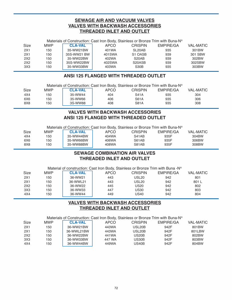
SEWAGE AIR AND VACUUM VALVESVALVES WITH BACKWASH ACCESSORIES
THREADED INLET AND OUTLET
Materials of Construction: Cast Iron Body, Stainless or Bronze Trim with Buna-N®
Size MWP CLA-VAL APCO CRISPIN EMPIRE/GA VAL-MATIC 2X1 150 35-WW21BW 401WA SL20AB 935 301BW
2X1 150 35S-WW21 BW 401SWA S1 OASB 939 301 SBW2X2 150 35-WW22BW 402WA S20AB 939 302BW2X2 150 35S-WW22BW 402SWA S20ASB 939 302SBW3X3 150 35-WW33BW 403WA S30B 935 303BW
ANSI 125 FLANGED WITH THREADED OUTLET
Materials of Construction: Cast Iron Body, Stainless or Bronze Trim with Buna-N®
Size MWP CLA-VAL APCO CRISPIN EMPIRE/GA VAL-MATIC4X4 150 35-WW44 404 S41A 935 3046X6 150 35-WW66 406 S61A 935 3068X8 150 3S-WW88 408 S81A 935 308
VALVES WITH BACKWASH ACCESSORIESANSI 125 FLANGED WITH THREADED OUTLET
Materials of Construction: Cast Iron Body, Stainless or Bronze Trim with Buna-N®
Size MWP CLA-VAL APCO CRISPIN EMPIRE/GA VAL-MATIC4X4 150 35-WW44BW 404WA S41AB 935F 304BW6X6 150 35-WW66BW 406WA S61AB 935F 306BW8X8 150 35-WW88BW 408WA S81AB 935F 308BW
SEWAGE COMBINATION AIR VALVESTHREADED INLET AND OUTLET
Material of construction: Cast Iron Body, Stainless or Bronze Trim with Buna -N®
Size MWP CLA-VAL APCO CRISPIN EMPIRE/GA VAL-MATIC2X1 150 36-WW21 443 USL20 942 8012X1 150 36-WWL21 443 USL20 942 801 L2X2 150 36-WW22 445 US20 942 8023X3 150 36-WW33 447 US30 942 803 4X4 150 36-WW44 449 US40 942 804
VALVES WITH BACKWASH ACCESSORIESTHREADED INLET AND OUTLET
Materials of Construction: Cast Iron Body, Stainless or Bronze Trim with Buna-N®
Size MWP CLA-VAL APCO CRISPIN EMPIRE/GA VAL-MATIC2X1 150 36-WW21BW 443WA USL20B 942F 801BW2X1 150 36-WWL21BW 443WA USL20B 942F 801LBW2X2 150 36-WW22BW 441WA US20B 942F 802BW3X3 150 36-WW33BW 447 WA US30B 942F 803BW4X4 150 36-WW44BW 449WA US40B 942F 804BW
72
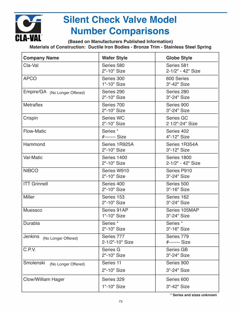
Company Name Wafer Style Globe Style
Cla-Val Series 580 Series 5812"-10" Size 2-1/2" - 42" Size
APCO Series 300 600 Series1"-10" Size 3"-42" Size
Empire/GA Series 290 Series 2802"-10" Size 3"-24" Size
Metraflex Series 700 Series 9002"-10" Size 3"-24" Size
Crispin Series WC Series GC2”-10” Size 2 1/2"-24" Size
Flow-Matic Series * Series 402#------- Size 4"-12" Size
Hammond Series 1R925A Series 1R354A2"-10" Size 3"-12" Size
Val-Matic Series 1400 Series 18002"-10" Size 2-1/2" - 42" Size
NIBCO Series W910 Series P9102"-10" Size 3"-24" Size
ITT Grinnell Series 400 Series 5002"-10" Size 3"-16" Size
Miller Series 153 Series 1622"-10" Size 3"-24" Size
Muessco Series 91AP Series 105MAP1"-10" Size 3"-24" Size
Durabla Series * Series *2"-10" Size 3"-16" Size
Jenkins Series 777 Series 7792-1/2"-10" Size #------- Size
C.P.V. Series G Series GB2"-10" Size 3"-24" Size
Smolenski Series 11 Series 9002"-10" Size 3"-24" Size
Clow/William Hager Series 329 Series 6001"-10" Size 3"-42" Size
(Based on Manufacturers Published Information)
Materials of Construction: Ductile Iron Bodies - Bronze Trim - Stainless Steel Spring
(No Longer Offered)
(No Longer Offered)
(No Longer Offered)
Silent Check Valve Model
Number Comparisons
* Series and sizes unknown
73
Limited Warranty
Air Valves as supplied by Cla-Val. are warranted for one yearfrom date of shipment against manufacturing defects in materialand workmanship that develop in the service for which they aredesigned, provided the products are installed and used in ac-cordance with all applicable instructions and limitations issuedby Cla-Val. Electronic components manufactured by Cla-Val arewarranted for one year from the date of shipment.We will repair or replace defective material, free of charge, whichis returned to our factory, transportation charges prepaid, pro-vided that, after inspection, the material is found to have beendefective at time of shipment. This warranty is expressly con-ditioned on the purchaser’s giving Cla-Val immediate written no-tice upon discovery of the defect.Components used by Cla-Val but manufactured by others, arewarranted only to the extent of that manufacturer’s guarantee.This warranty shall not apply if the product has been altered orrepaired by others, and Cla-Val shall make no allowance orcredit for such repairs or alterations unless authorized in writingby Cla-Val.
Disclaimer of Warranties and Limitations ofLiability
The foregoing warranty is exclusive and in lieu of all other war-ranties and representations, whether expressed, implied, oral orwritten, including but not limited to any implied warranties ormerchantability or fitness for a particular purpose. All such otherwarranties and representations are hereby cancelled.Cla-Val shall not be liable for any incidental or consequentialloss, damage or expense arising directly or indirectly from theuse of the product. Cla-Val shall not be liable for any damagesor charges for labor or expense in making repairs or adjust-ments to the product. Cla-Val shall not be liable for any dam-ages or charges sustained in the adaptation or use of itsengineering data and services. No representative of Cla-Valmay change any of the foregoing or assume any additional lia-bility or responsibility in connection with the product. The liabilityof Cla-Val is limited to material replacements F.O.B. NewportBeach, California.
Terms Of Sale
Acceptance Of Orders
All orders are subject to acceptance by our main office at New-port Beach, California.
Credit Terms
Credit terms are net thirty (30) days from date of invoice.
Purchase Order Forms
Orders submitted on customer’s own purchase order forms willbe accepted only with the express understanding that no state-ments, clauses, or conditions contained in said order form willbe binding on the Seller if they in any way modify the Seller’sown terms and conditions of sales.
Product Changes
The right is reserved to make changes in pattern, design or ma-terials when deemed necessary, without prior notice.
Prices
All prices are F.O.B. Newport Beach, California unless expresslystated otherwise on our acknowledgement of the order. Pricesare subject to change without notice. The prices at which anyorder is accepted are subject to adjustment to the Seller’s pricein effect at the time of shipment. Prices do not include sales, ex-cise, municipal, state or any other Government taxes. Minimumorder charge $100.00Responsibility
We will not be responsible for delays resulting from strikes, ac-cidents, negligence of carriers, or other causes beyond our con-trol. Also, we will not be liable for any unauthorized productalterations or charges accruing therefrom.
Risk
All goods are shipped at the risk of the purchaser after they havebeen delivered by us to the carrier. Claims for error, shortages,etc., must be made upon receipt of goods.
Export Shipments
Export shipments are subject to an additional charge for exportpacking.
Returned Goods
1. Customers must obtain written approval from Cla-Val prior toreturning any material.
2. Cla-Val reserves the right to refuse the return of any prod-ucts.
3. Products more than six (6) months old cannot be returnedfor credit.
4. Specially produced, non-standard models cannot be returnedfor credit.
5. Rubber goods such as diaphragms, discs, o-rings, etc., can-not be returned for credit, unless as part of an unopened vac-uum sealed repair kit which is less than six months old.
6. Goods authorized for return are subject to a 35% ($100 min-imum) restocking charge and a service charge for inspection,reconditioning, replacement of rubber parts, retesting, re-painting and repackaging as required.
7. Authorized returned goods must be packaged and shippedprepaid to Cla-Val,1701 Placentia Avenue, Costa Mesa, Cal-ifornia 92627.
WARRANTY
TERMS OF SALE
74
Air and Check Valvesfor water and wastewater applications
GLOBAL HEADQUARTERS1701 Placentia AvenueCosta Mesa, CA, CA 92627Phone: (949) 722-48001-800-942-6326 Fax: (949) 548-5441E-mail: [email protected]
CLA-VAL CANADA4687 Christie DriveBeamsville, Ontario Canada L0R 1B4Phone: (905) 563-4963E-mail: [email protected]
CLA-VAL EUROPEChemin dés Mesanges 1CH-1032 Romanel/LausanneSwitzerlandPhone: 41-21-643-15-55E-mail: [email protected]
CLA-VAL UKDainton HouseGoods Station RoadGB - Tunbridge WellsKent TN1 2 DHEnglandPhone: 44-1892-514-400E-mail: [email protected]
CLA-VAL FRANCEPorte du Grand Lyon 1ZI de Champ du PérierFrance - 01700 NeyonPhone: 33-4-72-25-92-93E-mail: [email protected]
Email for all US regions: [email protected]
WESTERN REGION11626 Sterling Avenue, Suite FRiverside, CA 92503Phone: (951) 687-91451-800-247-9090
CENTRAL REGION8707 Forney RoadDallas, TX 75227Phone: (214) 388-934931-800-533-8181
EASTERN REGION6911 Richmond Highway,Suite 444Alexandria, VA 22306Phone: (703) 721-19231-800-451-3030
CLA-VAL MEXICOAV Patria 2085Col. Puerta de Hierro45116, Zapopan, JaliscoPhone: + 52 (33) 80007565E-mail: [email protected]
CLA-VAL PACIFIC REGION45 Kennaway RoadWoolston, Christchurch, 8023New ZealandPhone: (64) 39644860E-mail: [email protected]
Air and Check Valve Catalog (R-08/2016)