Embed Size (px)
DESCRIPTION
3361907
Citation preview
Thermal Systems and Energy Efficiency Course Code: 3361907
GTU/ NITTTR Bhopal/14-15 Gujarat State
1
GUJARAT TECHNOLOGICAL UNIVERSITY, AHMEDABAD, GUJARAT
COURSE CURRICULUM
COURSE TITLE: THERMAL SYSTEMS AND ENERGY EFFICIENCY
(COURSE CODE: 3361907)
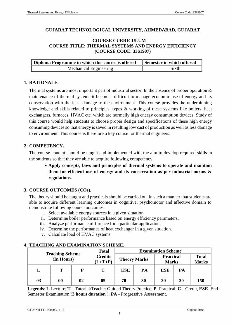
Diploma Programme in which this course is offered Semester in which offered
Mechanical Engineering Sixth
1. RATIONALE.
Thermal systems are most important part of industrial sector. In the absence of proper operation &
maintenance of thermal systems it becomes difficult to manage economic use of energy and its
conservation with the least damage to the environment. This course provides the underpinning
knowledge and skills related to principles, types & working of these systems like boilers, heat
exchangers, furnaces, HVAC etc. which are normally high energy consumption devices. Study of
this course would help students to choose proper design and specifications of these high energy
consuming devices so that energy is saved in resulting low cast of production as well as less damage
to environment. This course is therefore a key course for thermal engineers.
2. COMPETENCY.
The course content should be taught and implemented with the aim to develop required skills in
the students so that they are able to acquire following competency:
Apply concepts, laws and principles of thermal systems to operate and maintain
them for efficient use of energy and its conservation as per industrial norms &
regulations.
3. COURSE OUTCOMES (COs).
The theory should be taught and practicals should be carried out in such a manner that students are
able to acquire different learning outcomes in cognitive, psychomotor and affective domain to
demonstrate following course outcomes.
i. Select available energy sources in a given situation.
ii. Determine boiler performance based on energy efficiency parameters.
iii. Analyze performance of furnace for a particular application.
iv. Determine the performance of heat exchanger in a given situation.
v. Calculate load of HVAC systems.
4. TEACHING AND EXAMINATION SCHEME.
Teaching Scheme
(In Hours)
Total
Credits
(L+T+P)
Examination Scheme
Theory Marks Practical
Marks
Total
Marks
L T P C ESE PA ESE PA
150 03 00 02 05 70 30 20 30
Legends: L-Lecture; T – Tutorial/Teacher Guided Theory Practice; P -Practical; C – Credit, ESE -End
Semester Examination (3 hours duration ); PA - Progressive Assessment.
Thermal Systems and Energy Efficiency Course Code: 3361907
GTU/ NITTTR Bhopal/14-15 Gujarat State
2
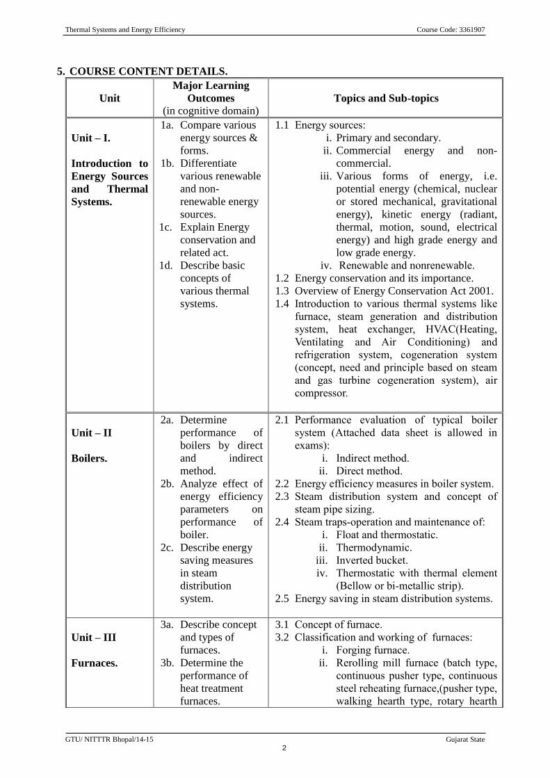
5. COURSE CONTENT DETAILS.
Unit
Major Learning
Outcomes
(in cognitive domain) Topics and Sub-topics
Unit – I.
Introduction to
Energy Sources
and Thermal
Systems.
1a. Compare various
energy sources &
forms.
1b. Differentiate
various renewable
and non-
renewable energy
sources.
1c. Explain Energy
conservation and
related act.
1d. Describe basic
concepts of
various thermal
systems.
1.1 Energy sources:
i. Primary and secondary.
ii. Commercial energy and non-
commercial.
iii. Various forms of energy, i.e.
potential energy (chemical, nuclear
or stored mechanical, gravitational
energy), kinetic energy (radiant,
thermal, motion, sound, electrical
energy) and high grade energy and
low grade energy.
iv. Renewable and nonrenewable.
1.2 Energy conservation and its importance.
1.3 Overview of Energy Conservation Act 2001.
1.4 Introduction to various thermal systems like
furnace, steam generation and distribution
system, heat exchanger, HVAC(Heating,
Ventilating and Air Conditioning) and
refrigeration system, cogeneration system
(concept, need and principle based on steam
and gas turbine cogeneration system), air
compressor.
Unit – II
Boilers.
2a. Determine
performance of
boilers by direct
and indirect
method.
2b. Analyze effect of
energy efficiency
parameters on
performance of
boiler.
2c. Describe energy
saving measures
in steam
distribution
system.
2.1 Performance evaluation of typical boiler
system (Attached data sheet is allowed in
exams):
i. Indirect method.
ii. Direct method.
2.2 Energy efficiency measures in boiler system.
2.3 Steam distribution system and concept of
steam pipe sizing.
2.4 Steam traps-operation and maintenance of:
i. Float and thermostatic.
ii. Thermodynamic.
iii. Inverted bucket.
iv. Thermostatic with thermal element
(Bellow or bi-metallic strip).
2.5 Energy saving in steam distribution systems.
Unit – III
Furnaces.
3a. Describe concept
and types of
furnaces.
3b. Determine the
performance of
heat treatment
furnaces.
3.1 Concept of furnace.
3.2 Classification and working of furnaces:
i. Forging furnace.
ii. Rerolling mill furnace (batch type,
continuous pusher type, continuous
steel reheating furnace,(pusher type,
walking hearth type, rotary hearth
Thermal Systems and Energy Efficiency Course Code: 3361907
GTU/ NITTTR Bhopal/14-15 Gujarat State
3
Unit
Major Learning
Outcomes
(in cognitive domain) Topics and Sub-topics
3c. Derive energy
efficiency
parameters.
type, continuous recirculating bogie
type etc.).
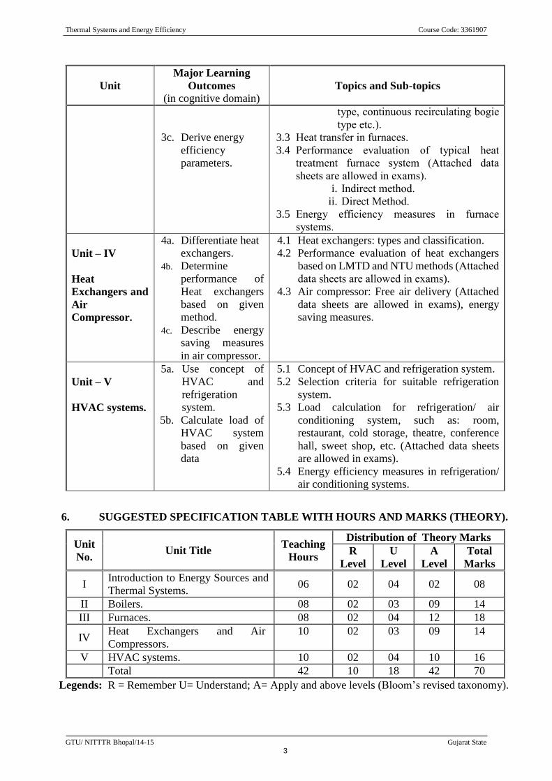
3.3 Heat transfer in furnaces.
3.4 Performance evaluation of typical heat
treatment furnace system (Attached data
sheets are allowed in exams).
i. Indirect method.
ii. Direct Method.
3.5 Energy efficiency measures in furnace
systems.
Unit – IV
Heat
Exchangers and
Air
Compressor.
4a. Differentiate heat
exchangers.
4b. Determine
performance of
Heat exchangers
based on given
method.
4c. Describe energy
saving measures
in air compressor.
4.1 Heat exchangers: types and classification.
4.2 Performance evaluation of heat exchangers
based on LMTD and NTU methods (Attached
data sheets are allowed in exams).
4.3 Air compressor: Free air delivery (Attached
data sheets are allowed in exams), energy
saving measures.
Unit – V
HVAC systems.
5a. Use concept of
HVAC and
refrigeration
system.
5b. Calculate load of
HVAC system
based on given
data
5.1 Concept of HVAC and refrigeration system.
5.2 Selection criteria for suitable refrigeration
system.
5.3 Load calculation for refrigeration/ air
conditioning system, such as: room,
restaurant, cold storage, theatre, conference
hall, sweet shop, etc. (Attached data sheets
are allowed in exams).
5.4 Energy efficiency measures in refrigeration/
air conditioning systems.
6. SUGGESTED SPECIFICATION TABLE WITH HOURS AND MARKS (THEORY).
Unit
No. Unit Title
Teaching
Hours
Distribution of Theory Marks
R
Level
U
Level
A
Level
Total
Marks
I Introduction to Energy Sources and
Thermal Systems. 06 02 04 02 08
II Boilers. 08 02 03 09 14
III Furnaces. 08 02 04 12 18
IV Heat Exchangers and Air
Compressors.
10 02 03 09 14
V HVAC systems. 10 02 04 10 16
Total 42 10 18 42 70
Legends: R = Remember U= Understand; A= Apply and above levels (Bloom’s revised taxonomy).
Thermal Systems and Energy Efficiency Course Code: 3361907
GTU/ NITTTR Bhopal/14-15 Gujarat State
4
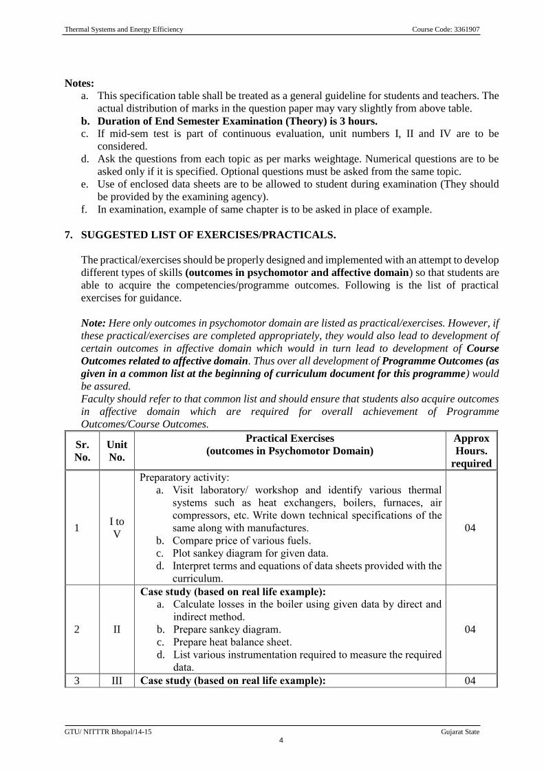
Notes:
a. This specification table shall be treated as a general guideline for students and teachers. The
actual distribution of marks in the question paper may vary slightly from above table.
b. Duration of End Semester Examination (Theory) is 3 hours.
c. If mid-sem test is part of continuous evaluation, unit numbers I, II and IV are to be
considered.
d. Ask the questions from each topic as per marks weightage. Numerical questions are to be
asked only if it is specified. Optional questions must be asked from the same topic.
e. Use of enclosed data sheets are to be allowed to student during examination (They should
be provided by the examining agency).
f. In examination, example of same chapter is to be asked in place of example.
7. SUGGESTED LIST OF EXERCISES/PRACTICALS.
The practical/exercises should be properly designed and implemented with an attempt to develop
different types of skills (outcomes in psychomotor and affective domain) so that students are
able to acquire the competencies/programme outcomes. Following is the list of practical
exercises for guidance.
Note: Here only outcomes in psychomotor domain are listed as practical/exercises. However, if
these practical/exercises are completed appropriately, they would also lead to development of
certain outcomes in affective domain which would in turn lead to development of Course
Outcomes related to affective domain. Thus over all development of Programme Outcomes (as
given in a common list at the beginning of curriculum document for this programme) would
be assured.
Faculty should refer to that common list and should ensure that students also acquire outcomes
in affective domain which are required for overall achievement of Programme
Outcomes/Course Outcomes.
Sr.
No.
Unit
No.
Practical Exercises
(outcomes in Psychomotor Domain)
Approx
Hours.
required
1 I to
V
Preparatory activity:
a. Visit laboratory/ workshop and identify various thermal
systems such as heat exchangers, boilers, furnaces, air
compressors, etc. Write down technical specifications of the
same along with manufactures.
b. Compare price of various fuels.
c. Plot sankey diagram for given data.
d. Interpret terms and equations of data sheets provided with the
curriculum.
04
2 II
Case study (based on real life example):
a. Calculate losses in the boiler using given data by direct and
indirect method.
b. Prepare sankey diagram.
c. Prepare heat balance sheet.
d. List various instrumentation required to measure the required
data.
04
3 III Case study (based on real life example): 04
Thermal Systems and Energy Efficiency Course Code: 3361907
GTU/ NITTTR Bhopal/14-15 Gujarat State
5
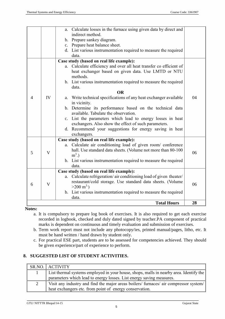
a. Calculate losses in the furnace using given data by direct and
indirect method.
b. Prepare sankey diagram.
c. Prepare heat balance sheet.
d. List various instrumentation required to measure the required
data.
4 IV
Case study (based on real life example):
a. Calculate efficiency and over all heat transfer co efficient of
heat exchanger based on given data. Use LMTD or NTU
methods.
b. List various instrumentation required to measure the required
data.
OR
a. Write technical specifications of any heat exchanger available
in vicinity.
b. Determine its performance based on the technical data
available. Tabulate the observation.
c. List the parameters which lead to energy losses in heat
exchangers. Also show the effect of such parameters.
d. Recommend your suggestions for energy saving in heat
exchangers.
04
5 V
Case study (based on real life example):
a. Calculate air conditioning load of given room/ conference
hall. Use standard data sheets. (Volume not more than 80-100
m3.)
b. List various instrumentation required to measure the required
data.
06
6 V
Case study (based on real life example):
a. Calculate refrigeration/ air conditioning load of given theater/
restaurant/cold storage. Use standard data sheets. (Volume
>200 m3.)
b. List various instrumentation required to measure the required
data.
06
Total Hours 28
Notes:
a. It is compulsory to prepare log book of exercises. It is also required to get each exercise
recorded in logbook, checked and duly dated signed by teacher.PA component of practical
marks is dependent on continuous and timely evaluation and submission of exercises.
b. Term work report must not include any photocopy/ies, printed manual/pages, litho, etc. It
must be hand written / hand drawn by student only.
c. For practical ESE part, students are to be assessed for competencies achieved. They should
be given experience/part of experience to perform.
8. SUGGESTED LIST OF STUDENT ACTIVITIES.
SR.NO. ACTIVITY
1 List thermal systems employed in your house, shops, malls in nearby area. Identify the
parameters which lead to energy losses. List energy saving measures.
2 Visit any industry and find the major areas boilers/ furnaces/ air compressor system/
heat exchangers etc. from point of energy conservation.
Thermal Systems and Energy Efficiency Course Code: 3361907
GTU/ NITTTR Bhopal/14-15 Gujarat State
6
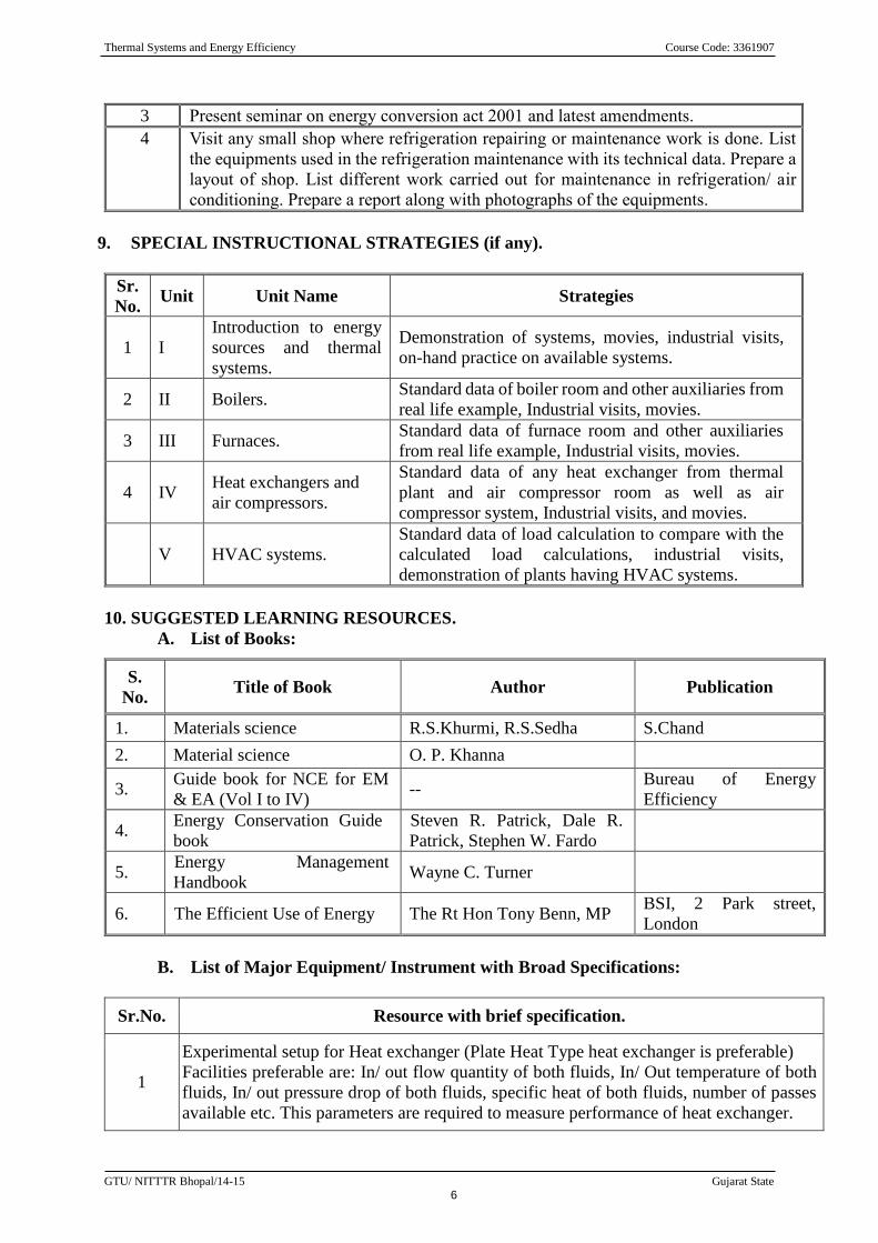
3 Present seminar on energy conversion act 2001 and latest amendments.
4 Visit any small shop where refrigeration repairing or maintenance work is done. List
the equipments used in the refrigeration maintenance with its technical data. Prepare a
layout of shop. List different work carried out for maintenance in refrigeration/ air
conditioning. Prepare a report along with photographs of the equipments.
9. SPECIAL INSTRUCTIONAL STRATEGIES (if any).
Sr.
No. Unit Unit Name Strategies
1 I
Introduction to energy
sources and thermal
systems.
Demonstration of systems, movies, industrial visits,
on-hand practice on available systems.
2 II Boilers. Standard data of boiler room and other auxiliaries from
real life example, Industrial visits, movies.
3 III Furnaces. Standard data of furnace room and other auxiliaries
from real life example, Industrial visits, movies.
4 IV Heat exchangers and
air compressors.
Standard data of any heat exchanger from thermal
plant and air compressor room as well as air
compressor system, Industrial visits, and movies.
V HVAC systems.
Standard data of load calculation to compare with the
calculated load calculations, industrial visits,
demonstration of plants having HVAC systems.
10. SUGGESTED LEARNING RESOURCES.
A. List of Books:
S.
No. Title of Book Author Publication
1. Materials science R.S.Khurmi, R.S.Sedha S.Chand
2. Material science O. P. Khanna
3. Guide book for NCE for EM
& EA (Vol I to IV) --
Bureau of Energy
Efficiency
4. Energy Conservation Guide
book
Steven R. Patrick, Dale R.
Patrick, Stephen W. Fardo
5. Energy Management
Handbook Wayne C. Turner
6. The Efficient Use of Energy The Rt Hon Tony Benn, MP BSI, 2 Park street,
London
B. List of Major Equipment/ Instrument with Broad Specifications:
Sr.No. Resource with brief specification.
1
Experimental setup for Heat exchanger (Plate Heat Type heat exchanger is preferable)
Facilities preferable are: In/ out flow quantity of both fluids, In/ Out temperature of both
fluids, In/ out pressure drop of both fluids, specific heat of both fluids, number of passes
available etc. This parameters are required to measure performance of heat exchanger.
Thermal Systems and Energy Efficiency Course Code: 3361907
GTU/ NITTTR Bhopal/14-15 Gujarat State
7
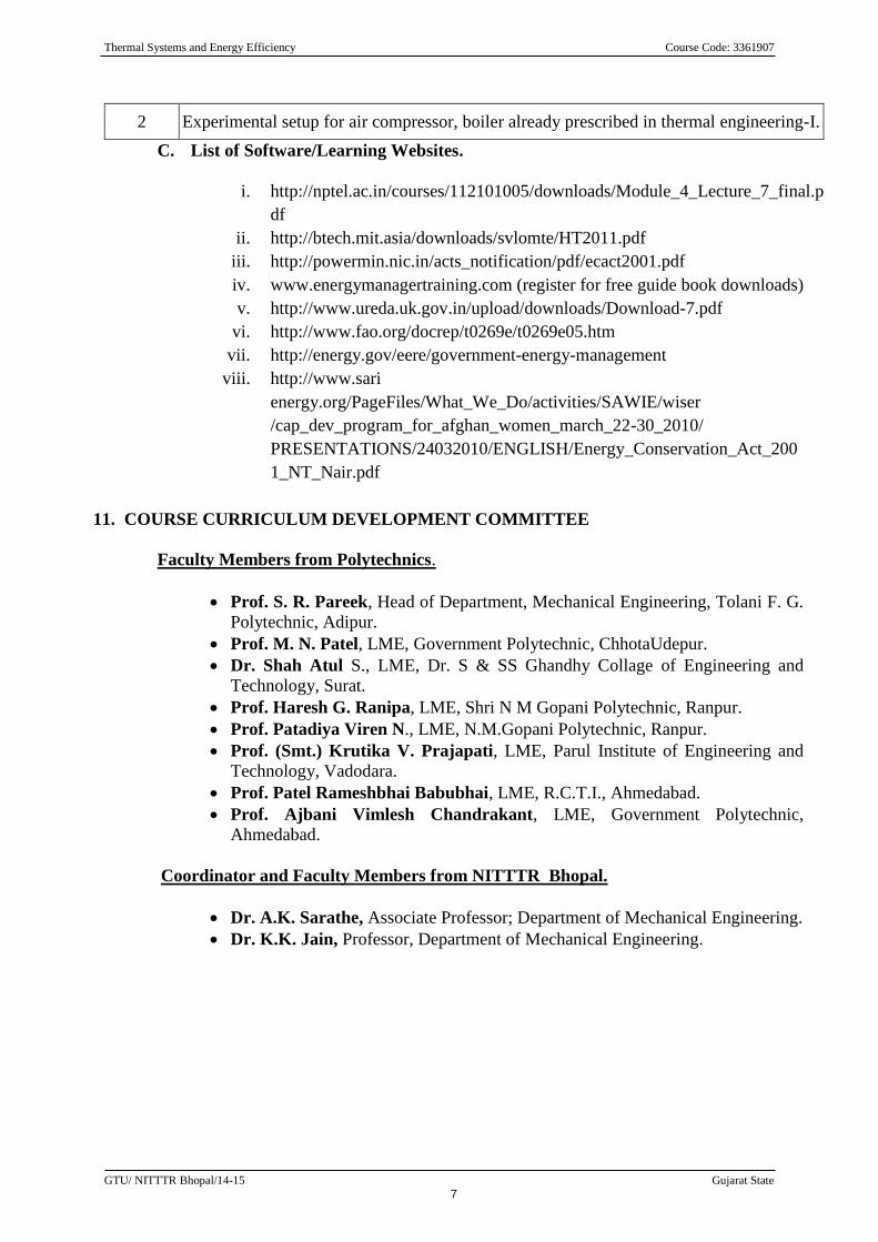
2 Experimental setup for air compressor, boiler already prescribed in thermal engineering-I.
C. List of Software/Learning Websites.
i. http://nptel.ac.in/courses/112101005/downloads/Module_4_Lecture_7_final.p
df
ii. http://btech.mit.asia/downloads/svlomte/HT2011.pdf
iii. http://powermin.nic.in/acts_notification/pdf/ecact2001.pdf
iv. www.energymanagertraining.com (register for free guide book downloads)
v. http://www.ureda.uk.gov.in/upload/downloads/Download-7.pdf
vi. http://www.fao.org/docrep/t0269e/t0269e05.htm
vii. http://energy.gov/eere/government-energy-management
viii. http://www.sari
energy.org/PageFiles/What_We_Do/activities/SAWIE/wiser
/cap_dev_program_for_afghan_women_march_22-30_2010/
PRESENTATIONS/24032010/ENGLISH/Energy_Conservation_Act_200
1_NT_Nair.pdf
11. COURSE CURRICULUM DEVELOPMENT COMMITTEE
Faculty Members from Polytechnics.
Prof. S. R. Pareek, Head of Department, Mechanical Engineering, Tolani F. G.
Polytechnic, Adipur.
Prof. M. N. Patel, LME, Government Polytechnic, ChhotaUdepur.
Dr. Shah Atul S., LME, Dr. S & SS Ghandhy Collage of Engineering and
Technology, Surat.
Prof. Haresh G. Ranipa, LME, Shri N M Gopani Polytechnic, Ranpur.
Prof. Patadiya Viren N., LME, N.M.Gopani Polytechnic, Ranpur.
Prof. (Smt.) Krutika V. Prajapati, LME, Parul Institute of Engineering and
Technology, Vadodara.
Prof. Patel Rameshbhai Babubhai, LME, R.C.T.I., Ahmedabad.
Prof. Ajbani Vimlesh Chandrakant, LME, Government Polytechnic,
Ahmedabad.
Coordinator and Faculty Members from NITTTR Bhopal.
Dr. A.K. Sarathe, Associate Professor; Department of Mechanical Engineering.
Dr. K.K. Jain, Professor, Department of Mechanical Engineering.
Thermal Systems and Energy Efficiency Course Code: 3361907
GTU/ NITTTR Bhopal/14-15 Gujarat State
8
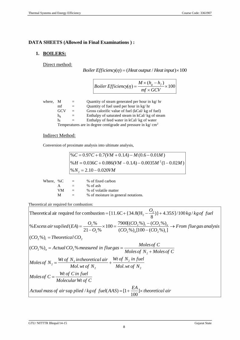
DATA SHEETS (Allowed in Final Examinations ) :
1. BOILERS:
Direct method:
100)/()( inputHeatoutputHeatEfficiencyBoiler
100)(
)(
GCVmf
hhMEfficiencyBoiler
fg
where, M = Quantity of steam generated per hour in kg/ hr
mf = Quantity of fuel used per hour in kg/ hr
GCV = Gross calorific value of fuel (kCal/ kg of fuel)
hg = Enthalpy of saturated steam in kCal/ kg of steam
hf = Enthalpy of feed water in kCal/ kg of water
Temperatures are in degree centigrade and pressure in kg/ cm2
Indirect Method:
Conversion of proximate analysis into ultimate analysis,
VMN
MMAVMCH
MMAVMCC
020.010.2%
)02.01(0035.0)1.0(086.0036.0%
)01.06.0()1.0(7.097.0%
2
2
Where, %C = % of fixed carbon
A = % of ash
VM = % of volatile matter
M = % of moisture in general notations.
Theoretical air required for combustion:
airltheoreticaEA
AASfuelofkgpliedairofmassActual
CofWtMolecular
fuelinCofWtCofMoles
NofwtMol
fuelinNofWt
NofwtMol
airltheoreticainNofWtNofMoles
CofMolesNofMoles
CofMolesgasflueinmeasuredCOActualCO
COlTheoreticaCO
analysisgasflueFromCOCO
COCO
O
OEAliedairExcess
fuelofkgkgSO
a
t
ta
at
]100
1[)(/sup
..
%%)(
%)(
]%)(100[%)(
%)(%)[(7900100
%21
%)(sup%
/100/]35.4)}8
{34.8(H[11.6Ccombustionfor requiredair lTheoretica
2
2
2
22
2
22
22
22
22
2
2
22
Thermal Systems and Energy Efficiency Course Code: 3361907
GTU/ NITTTR Bhopal/14-15 Gujarat State
9
2)32
64(]
100
23)[()
100
77()
12
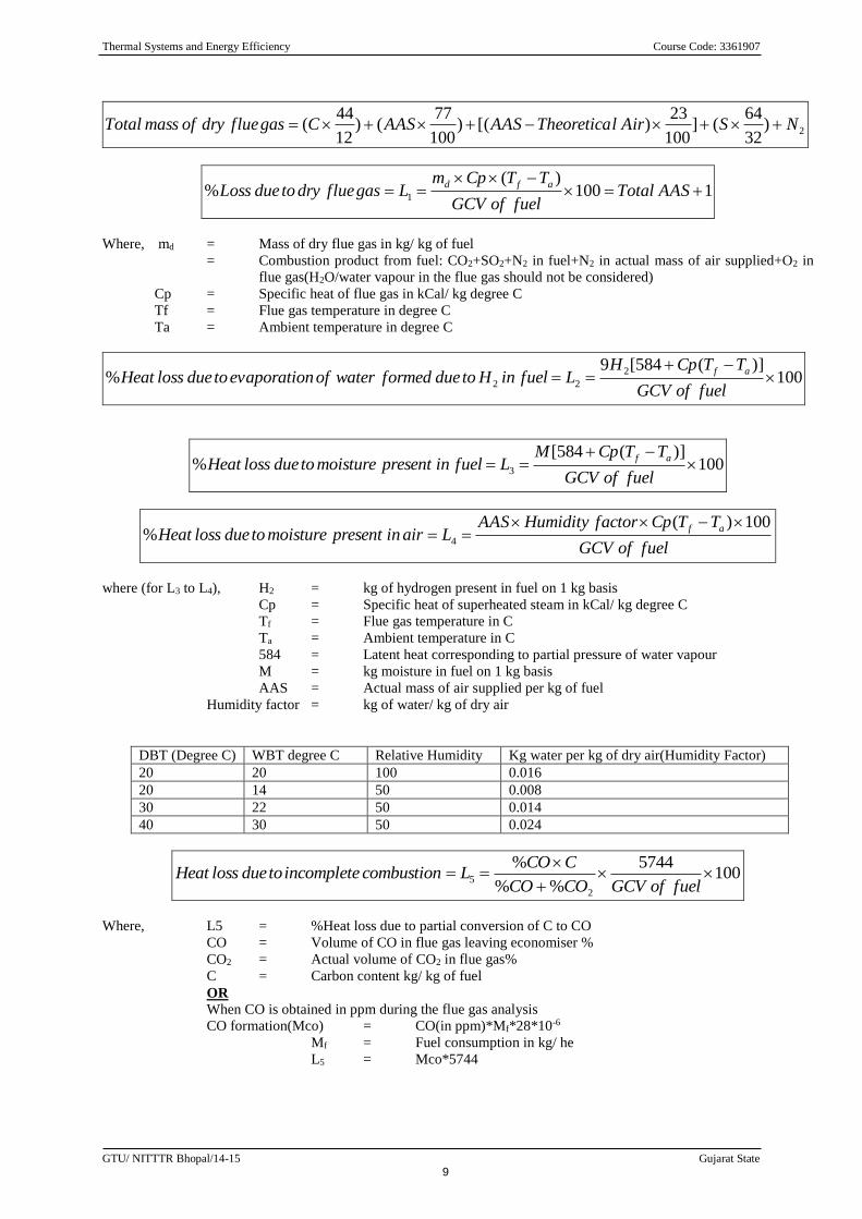
44( NSAirlTheoreticaAASAASCgasfluedryofmassTotal
1100)(
% 1
AASTotalfuelofGCV
TTCpmLgasfluedrytodueLoss
afd
Where, md = Mass of dry flue gas in kg/ kg of fuel
= Combustion product from fuel: CO2+SO2+N2 in fuel+N2 in actual mass of air supplied+O2 in
flue gas(H2O/water vapour in the flue gas should not be considered)
Cp = Specific heat of flue gas in kCal/ kg degree C
Tf = Flue gas temperature in degree C
Ta = Ambient temperature in degree C
100)](584[9
%2
22
fuelofGCV
TTCpHLfuelinHtodueformedwaterofnevaporatiotoduelossHeat
af
100)](584[
% 3
fuelofGCV
TTCpMLfuelinpresentmoisturetoduelossHeat
af
fuelofGCV
TTCpfactorHumidityAASLairinpresentmoisturetoduelossHeat
af 100)(% 4
where (for L3 to L4), H2 = kg of hydrogen present in fuel on 1 kg basis
Cp = Specific heat of superheated steam in kCal/ kg degree C
Tf = Flue gas temperature in C
Ta = Ambient temperature in C
584 = Latent heat corresponding to partial pressure of water vapour
M = kg moisture in fuel on 1 kg basis
AAS = Actual mass of air supplied per kg of fuel
Humidity factor = kg of water/ kg of dry air
DBT (Degree C) WBT degree C Relative Humidity Kg water per kg of dry air(Humidity Factor)
20 20 100 0.016
20 14 50 0.008
30 22 50 0.014
40 30 50 0.024
1005744
%%
%
2
5
fuelofGCVCOCO
CCOLcombustionincompletetoduelossHeat
Where, L5 = %Heat loss due to partial conversion of C to CO
CO = Volume of CO in flue gas leaving economiser %
CO2 = Actual volume of CO2 in flue gas%
C = Carbon content kg/ kg of fuel
OR
When CO is obtained in ppm during the flue gas analysis
CO formation(Mco) = CO(in ppm)*Mf*28*10-6
Mf = Fuel consumption in kg/ he
L5 = Mco*5744
Thermal Systems and Energy Efficiency Course Code: 3361907
GTU/ NITTTR Bhopal/14-15 Gujarat State
10
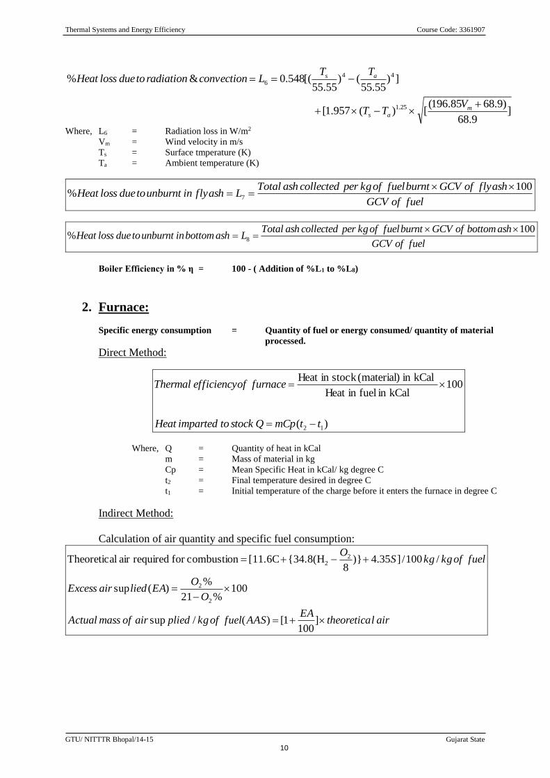
]9.68
)9.6885.196([)(957.1[
])55.55
()55.55
[(548.0&%
25.1
44
6
mas
as
VTT
TTLconvectionradiationtoduelossHeat
Where, L6 = Radiation loss in W/m2
Vm = Wind velocity in m/s
Ts = Surface tmperature (K)
Ta = Ambient temperature (K)
fuelofGCV
ashflyofGCVburntfuelofkgpercollectedashTotalLashflyinunburnttoduelossHeat
100% 7
fuelofGCV
ashbottomofGCVburntfuelofkgpercollectedashTotalLashbottominunburnttoduelossHeat
100% 8
Boiler Efficiency in % η = 100 - ( Addition of %L1 to %L8)
2. Furnace:
Specific energy consumption = Quantity of fuel or energy consumed/ quantity of material
processed.
Direct Method:
)(
100kCalin fuelin Heat
kCalin (material)stock in Heat
12 ttmCpQstocktoimpartedHeat
furnaceofefficiencyThermal
Where, Q = Quantity of heat in kCal
m = Mass of material in kg
Cp = Mean Specific Heat in kCal/ kg degree C
t2 = Final temperature desired in degree C
t1 = Initial temperature of the charge before it enters the furnace in degree C
Indirect Method:
Calculation of air quantity and specific fuel consumption:
airltheoreticaEA
AASfuelofkgpliedairofmassActual
O
OEAliedairExcess
fuelofkgkgSO
]100
1[)(/sup
100%21
%)(sup
/100/]35.4)}8
{34.8(H[11.6Ccombustionfor requiredair lTheoretica
2
2
22
Thermal Systems and Energy Efficiency Course Code: 3361907
GTU/ NITTTR Bhopal/14-15 Gujarat State
11
2
22
22
)32
64(]
100
23)[()
100
77()
12
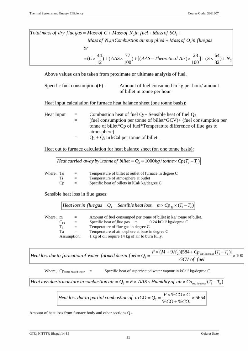
44(
sup
NSAirlTheoreticaAASAASC
or
gasflueinOofMasspliedairCombustioninNofMass
SOofMassfuelinNofMassCofMassgasfluedryofmassTotal
Above values can be taken from proximate or ultimate analysis of fuel.
Specific fuel consumption(F) = Amount of fuel consumed in kg per hour/ amount
of billet in tonne per hour
Heat input calculation for furnace heat balance sheet (one tonne basis):
Heat Input = Combustion heat of fuel Q1+ Sensible heat of fuel Q2
= (fuel consumption per tonne of billet*GCV)+ (fuel consumption per
tonne of billet*Cp of fuel*Temperature difference of flue gas to
atmosphere)
= Q1 + Q2 in kCal per tonne of billet.
Heat out to furnace calculation for heat balance sheet (on one tonne basis):
)(/10001 3 io TTCptonnekgQbilletoftonnebyawaycarriedHeat
Where, To = Temperature of billet at outlet of furnace in degree C
Ti = Temperature of atmosphere at outlet
Cp = Specific heat of billets in lCal/ kg/degree C
Sensible heat loss in flue gases:
)( 14 afg TTCpmlossheatSensibleQgasflueinlossHeat
Where, m = Amount of fuel consumped per tonne of billet in kg/ tonne of billet.
Cpg = Specific heat of flue gas ~ 0.24 kCal/ kg/degree C
T1 = Temperature of flue gas in degree C
Ta = Temperature of atmosphere at base in degree C
Assumption: 1 kg of oil require 14 kg of air to burn fully.
100)](584)[9( 1.sup2
5
fuelofGCV
TTCpHMFQfuelindueformedwaterofformationtoduelossHeat
awatheat
Where, Cpsuper heated water = Specific heat of superheated water vapour in kCal/ kg/degree C
)( 1sup6 awatheat TTCpairofHumidityAASFQaircombustioninmoisturetoduelossHeat
5654%%
%
2
7
COCO
CCOFQCOtoofcombustionpartialtoduelossHeat
Amount of heat loss from furnace body and other sections Q7
Thermal Systems and Energy Efficiency Course Code: 3361907
GTU/ NITTTR Bhopal/14-15 Gujarat State
12
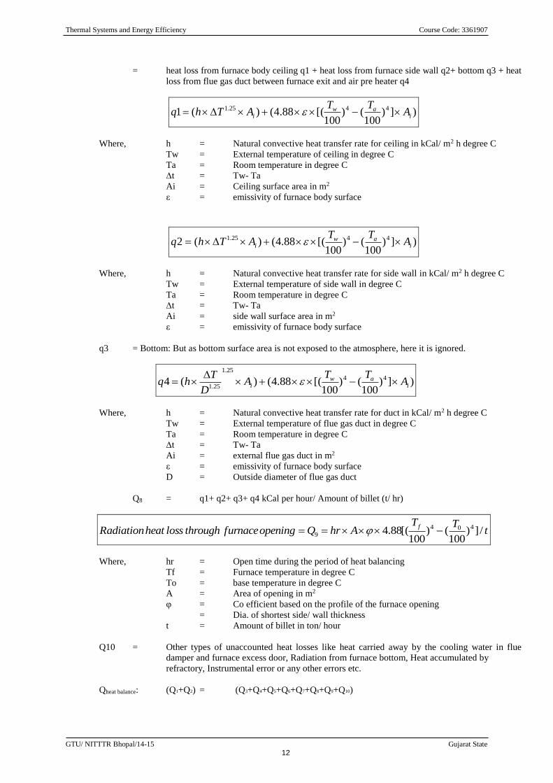
= heat loss from furnace body ceiling q1 + heat loss from furnace side wall q2+ bottom q3 + heat
loss from flue gas duct between furnace exit and air pre heater q4
)])100
()100
[(88.4()(1 4425.1
iaw
i ATT
AThq
Where, h = Natural convective heat transfer rate for ceiling in kCal/ m2 h degree C
Tw = External temperature of ceiling in degree C
Ta = Room temperature in degree C
∆t = Tw- Ta
Ai = Ceiling surface area in m2
ε = emissivity of furnace body surface
)])100
()100
[(88.4()(2 4425.1
iaw
i ATT
AThq
Where, h = Natural convective heat transfer rate for side wall in kCal/ m2 h degree C
Tw = External temperature of side wall in degree C
Ta = Room temperature in degree C
∆t = Tw- Ta
Ai = side wall surface area in m2
ε = emissivity of furnace body surface
q3 = Bottom: But as bottom surface area is not exposed to the atmosphere, here it is ignored.
)])100
()100
[(88.4()(4 44
25.1
25.1 iaw
i ATT
AD
Thq
Where, h = Natural convective heat transfer rate for duct in kCal/ m2 h degree C
Tw = External temperature of flue gas duct in degree C
Ta = Room temperature in degree C
∆t = Tw- Ta
Ai = external flue gas duct in m2
ε = emissivity of furnace body surface
D = Outside diameter of flue gas duct
Q8 = q1+ q2+ q3+ q4 kCal per hour/ Amount of billet (t/ hr)
tTT
AhrQopeningfurnacethroughlossheatRadiationf
/])100
()100
[(88.4 404
9
Where, hr = Open time during the period of heat balancing
Tf = Furnace temperature in degree C
To = base temperature in degree C
A = Area of opening in m2
φ = Co efficient based on the profile of the furnace opening
= Dia. of shortest side/ wall thickness
t = Amount of billet in ton/ hour
Q10 = Other types of unaccounted heat losses like heat carried away by the cooling water in flue
damper and furnace excess door, Radiation from furnace bottom, Heat accumulated by
refractory, Instrumental error or any other errors etc.
Qheat balance: (Q1+Q2) = (Q3+Q4+Q5+Q6+Q7+Q8+Q9+Q10)
Thermal Systems and Energy Efficiency Course Code: 3361907
GTU/ NITTTR Bhopal/14-15 Gujarat State
13
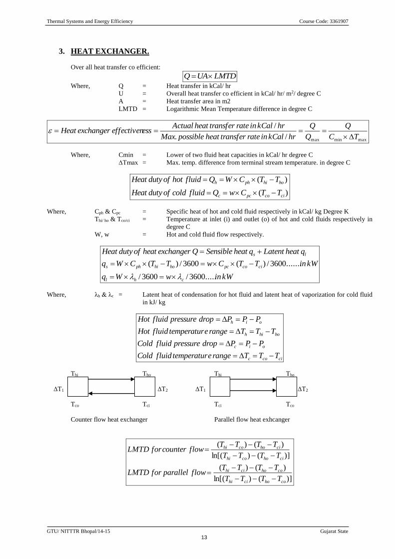
3. HEAT EXCHANGER.
Over all heat transfer co efficient:
LMTDUAQ
Where, Q = Heat transfer in kCal/ hr
U = Overall heat transfer co efficient in kCal/ hr/ m2/ degree C
A = Heat transfer area in m2
LMTD = Logarithmic Mean Temperature difference in degree C
maxminmax/.
/
TC
Q
Q
Q
hrkCalinratetransferheatpossibleMax
hrkCalinratetransferheatActualesseffectivenexchangerHeat
Where, Cmin = Lower of two fluid heat capacities in kCal/ hr degree C
∆Tmax = Max. temp. difference from terminal stream temperature. in degree C
)(
)(
cicopcc
hohiphh
TTCwQfluidcoldofdutyHeat
TTCWQfluidhotofdutyHeat
Where, Cph & Cpc = Specific heat of hot and cold fluid respectively in kCal/ kg Degree K
Thi/ ho & Tco/ci = Temperature at inlet (i) and outlet (o) of hot and cold fluids respectively in
degree C
W, w = Hot and cold fluid flow respectively.
kWinwWq
kWinTTCwTTCWq
qheatLatentqheatSensibleQexchangerheatofdutyHeat
chl
cicopchohiphs
ls
.....3600/3600/
.......3600/)(3600/)(
Where, λh & λc = Latent heat of condensation for hot fluid and latent heat of vaporization for cold fluid
in kJ/ kg
cicoc
oic
hohih
oih
TTTrangeetemperaturfluidCold
PPPdroppressurefluidCold
TTTrangeetemperaturfluidHot
PPPdroppressurefluidHot
Thi Tho Thi Tho
∆T1 ∆T2 ∆T1 ∆T2
Tco Tci Tci Tco
Counter flow heat exchanger Parallel flow heat exhcanger
)]()ln[(
)()(
)]()ln[(
)()(
cohocihi
cohocihi
cihocohi
cihocohi
TTTT
TTTTflowparallelforLMTD
TTTT
TTTTflowcounterforLMTD
Thermal Systems and Energy Efficiency Course Code: 3361907
GTU/ NITTTR Bhopal/14-15 Gujarat State
14
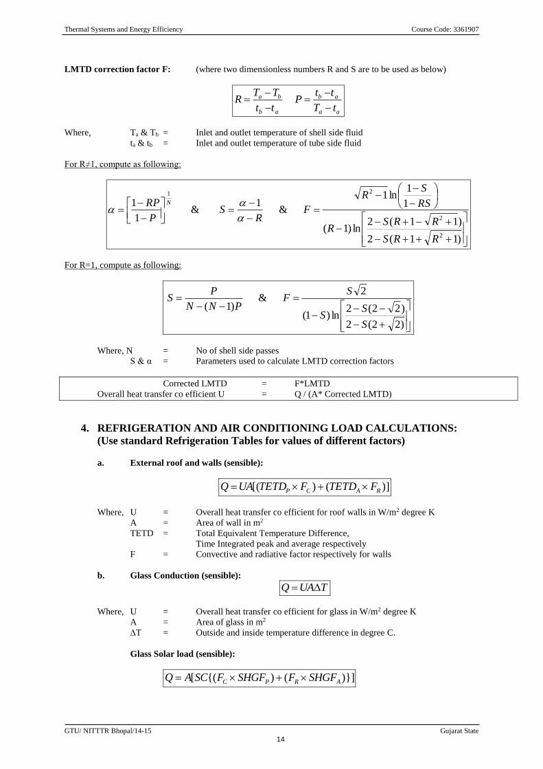
LMTD correction factor F: (where two dimensionless numbers R and S are to be used as below)
aa
ab
ab
ba
tT
ttP
tt
TTR
Where, Ta & Tb = Inlet and outlet temperature of shell side fluid
ta & tb = Inlet and outlet temperature of tube side fluid
For R≠1, compute as following:
)11(2
)11(2ln)1(
1
1ln1
&1
&1
1
2
2
21
RRS
RRSR
RS
SR
FR
SP
RP N
For R=1, compute as following:
)22(2
)22(2ln)1(
2&
)1(
S
SS
SF
PNN
PS
Where, N = No of shell side passes
S & α = Parameters used to calculate LMTD correction factors
Corrected LMTD = F*LMTD
Overall heat transfer co efficient U = Q / (A* Corrected LMTD)
4. REFRIGERATION AND AIR CONDITIONING LOAD CALCULATIONS:
(Use standard Refrigeration Tables for values of different factors)
a. External roof and walls (sensible):
)]()[( RACP FTETDFTETDUAQ
Where, U = Overall heat transfer co efficient for roof walls in W/m2 degree K
A = Area of wall in m2
TETD = Total Equivalent Temperature Difference,
Time Integrated peak and average respectively
F = Convective and radiative factor respectively for walls
b. Glass Conduction (sensible):
TUAQ
Where, U = Overall heat transfer co efficient for glass in W/m2 degree K
A = Area of glass in m2
∆T = Outside and inside temperature difference in degree C.
Glass Solar load (sensible):
)}](){([ ARPC SHGFFSHGFFSCAQ
Thermal Systems and Energy Efficiency Course Code: 3361907
GTU/ NITTTR Bhopal/14-15 Gujarat State
15
Where, A = Glass Area m2
SHGF = Solar heat gain factor for peak and average
SC = Shading co efficient
F = Convective and radiative factor respectively for glass
c. Ceiling/ Roof/ Floor/ Partition sensible (not exposed):
TUAQ
Where, U = Overall heat transfer co efficient for Ceiling/ Roof/ Floor/ Partition in W/m2 degree K
A = Area of Ceiling/ Roof/ Floor/ Partition in m2
∆T = Outside and inside temperature difference in degree C.
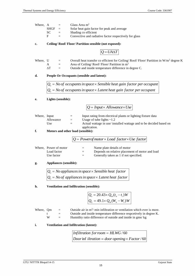
d. People Or Occupants (sensible and latent):
occupantperfactorgainheatLatentspaceinoccupantsofNoQ
occupantperfactorgainheatSensiblespaceinoccupantsofNoQ
s
s
e. Lights (sensible):
UseAllowanceInputQ
Where, Input = Input rating from electrical plants or lighting fixture data
Allowance = Usage of tube lights ~1.2
Use = Actual wattage in use/ installed wattage and to be decided based on
application.
f. Motors and other load (sensible):
factorUsefactorLoadmotorofPowerQ
Where, Power of motor = Name plate details of motor
Load factor = Depends on relative placement of motor and load
Use factor = Generally taken as 1 if not specified.
g. Appliances (sensible):
factorheatLatentspaceinappliancesofNoQ
factorheatSensiblespaceinappliancesNoQ
s
s
h. Ventilation and Infiltration (sensible):
WWWQQ
WttQQ
iomL
ioms
)(1.49
)(43.20
Where, Qm = Outside air in m3/ min infiltration or ventilation which ever is more.
t = Outside and inside temperature difference respcetively in degree K.
W = Humidity ratio difference of outside and inside in gms/ kg
i. Ventilation and Infiltration (latent):
60/inf
60/
FactoropeningdooriltrationDoor
HLWGroomforonInfiltrati
Thermal Systems and Energy Efficiency Course Code: 3361907
GTU/ NITTTR Bhopal/14-15 Gujarat State
16
Where, H = Room height in m.
W = Room width in m
L = Room Length in m
G = Factor for infiltration
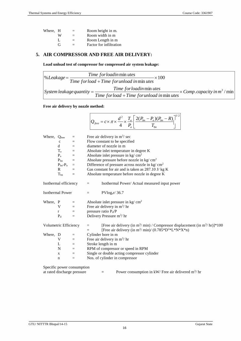
5. AIR COMPRESSOR AND FREE AIR DELIVERY:
Load unload test of compressor for compressed air system leakage:
min/.min
min
100min
min%
3mincapacityComputesinunloadforTimeloadforTime
utesinloadforTimequantityleakageSystem
utesinunloadforTimeloadforTime
utesinloadforTimeLeakage
Free air delivery by nozzle method:
2/1
2 ))((2
4
bn
bnnbn
a
afree
T
RPPP
P
TdcQ
Where, Qfree = Free air delivery in m3/ sec
c = Flow constant to be specified
d = diameter of nozzle in m
Ta = Absolute inlet temperature in degree K
Pa = Absolute inlet pressure in kg/ cm2
Pbn = Absolute pressure before nozzle in kg/ cm2
Pbn-Pn = Difference of pressure across nozzle in kg/ cm2
R = Gas constant for air and is taken as 287.10 J/ kg K
Tbn = Absolute temperature before nozzle in degree K
Isothermal efficiency = Isothermal Power/ Actual measured input power
Isothermal Power = PVloger/ 36.7
Where, P = Absolute inlet pressure in kg/ cm2
V = Free air delivery in m3/ hr
r = pressure ratio Pd/P
Pd = Delivery Pressure m3/ hr
Volumetric Efficiency = [Free air delivery (in m3/ min) / Compressor displacement (in m3/ hr)]*100
= [Free air delivery (in m3/ min)/ (0.785*D2*L*N*X*n)
Where, D = Cylinder bore in m
V = Free air delivery in m3/ hr
L = Stroke length in m
N = RPM of compressor or speed in RPM
x = Single or double acting compressor cylinder
n = Nos. of cylinder in compressor
Specific power consumption
at rated discharge pressure = Power consumption in kW/ Free air delivered m3/ hr
Thermal Systems and Energy Efficiency Course Code: 3361907
GTU/ NITTTR Bhopal/14-15 Gujarat State
17
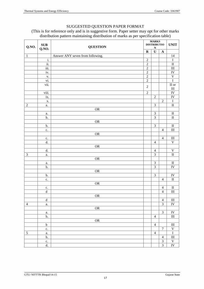
SUGGESTED QUESTION PAPER FORMAT
(This is for reference only and is in suggestive form. Paper setter may opt for other marks
distribution pattern maintaining distribution of marks as per specification table)
Q.NO. SUB
Q.NO. QUESTION
MARKS
DISTRIBUTIO
N UNIT
R U A
1 Answer ANY seven from following. 14
i. 2 I
ii. 2 II
iii. 2 III
iv. 2 IV
v. 2 V
vi. 2 I
vii. 2
II or
III
viii. 2 IV
ix. 2 IV
x. 2 I
2 a. 3 II
OR
a. 3 II
b. 3 II
OR
b. 3 II
c. 4 III
OR
c. 4 III
d. 4 V
OR
d. 4 V
3 a. 3 II
OR
a. 3 II
b. 3 IV
OR
b. 3 IV
c. 4 II
OR
c. 4 II
d 4 III
OR
d 4 III
4 a. 3 IV
OR
a. 3 IV
b. 4 III
OR
b 4 III
c. 7 V
5 a. 4 I
b. 4 III
c. 3 V
d. 3 IV


