Embed Size (px)
Citation preview

Preventive maintenance program
Guide for Group B public water systems using groundwater August 2013
DOH 331-351b Revised

Contents
Introduction Recommended preventive maintenance
Daily Weekly Monthly Quarterly Biannually Annually As needed
Recommended websites and publications Troubleshooting guides
Groundwater sources Submersible well pump systems Pressure tanks Storage facilities Hypochlorination problems Distribution systems Cross connections Sampling and monitoring
Template: Create your own preventive maintenance program If you need this publication in alternate format, call (800) 825-0127. For TTY/TDD, call (800) 833-6388.

Preventive maintenance program Page 3 Guide for Group B public water systems using groundwater
Introduction
Why is a preventive maintenance program important to me? A preventive maintenance program can prevent problems by helping you maintain your system properly. Knowing the ongoing needs of your system and taking action to meet those needs will enhance public health protection, improve your system’s reliability, and reduce the costs of maintaining your water system. How will this preventive maintenance program guide help me? This guide provides a schedule of routine operation and maintenance (O&M) tasks for Group B drinking water systems using groundwater supply. How is this guide organized? This guide has four major sections. We designed each section to guide you through developing a preventive maintenance program for your water system.
1. Recommended Preventive Maintenance: A narrative of daily, weekly, monthly, and annual operation and maintenance (O&M) tasks.
2. Recommended Websites and Publications: Resources to help you find more detailed information or guidance.
3. Troubleshooting Guides: Guidance to help you troubleshoot problems with your water system. We organized it by water system component so it is easier to find troubleshooting guidance for a specific component.
4. Recommended Operation and Maintenance Schedules: We organized the O&M section by water system component so you can post the schedules where you can see the tasks you need to do. We did not define all tasks in the checklist because they are self-explanatory.
How can I customize these tools for my system? Based on your system’s requirements, you can add, subtract, or modify tasks and logs from this guide to meet your preventive maintenance program needs. Maintain a log of all preventive maintenance completed on your water system. It is also important to document quantitative measurements, such as water levels, pressure readings, and so on. Photographs with adequate field notes or videotape with audio explanation can be valuable tools. We cannot over emphasize the importance of keeping records and documenting maintenance activities. Consistent forms and checklists help to ensure that you inspect and evaluate the same points each time. Organize and store records so they are readily accessible to verify that your water system is performing maintenance tasks and operational surveillance properly. Simple ways to organize your records include filing cabinets or card index files.

Page 4 Preventive maintenance program Guide for Group B public water systems using groundwater
Recommended preventive maintenance
Daily
Weekly Monthly
Quarterly Biannually
Annually As needed

Preventive maintenance program Page 5 Guide for Group B public water systems using groundwater
Daily
Read source water meter and record water production. You should have a working, properly calibrated master water meter at each source of supply to accurately measure and record production. Take routine source-water meter readings and record them in a log. Calculate the amount of water used during a time period, usually daily or weekly, by subtracting the previous meter reading from the current meter reading. You can use data on your water system’s water use throughout the year to evaluate source capacity, water rights, unusually high or low flows, excessive leakage, reduced pump output, unauthorized water use, and the adequacy of the treatment system capacity. Measure and record chlorine residuals. Public water systems adding chlorine on a continuous basis—either for disinfection or in support of another treatment objective, such as iron removal—should monitor and record the free chlorine residual level daily. It is essential to understand the treatment objective for chlorine addition. The frequency of free chlorine residual sampling, and the required level of chlorine, will vary depending on the reason the system adds chlorine.
Chlorination for disinfection Some drinking water supplies require disinfection because of concerns over source water quality. Systems with such sources must monitor and record free chlorine residual each calendar day at the “point of entry” to the distribution system, which is usually at or before the first customer connection downstream of the source. We will specify the minimum residual concentration required at the point of entry. Some drinking water supplies require disinfection because of concerns over the distribution system water quality. Applying chlorine at the source is the best way to ensure a consistent and reliable level of chlorine in the distribution system. Such systems must monitor and record free chlorine residual each working day (Monday – Friday, except holidays). The system must maintain free chlorine residual in the distribution system at a detectable level. We recommend a minimum chlorine residual of 0.2 milligrams per liter (mg/L).
Other treatment objectives
Some drinking water supplies must add chlorine to support a treatment objective other than disinfection (iron removal, for example). Such systems must monitor and record free chlorine residual each working day (Monday – Friday, except holidays), but we may approve of a reduced monitoring schedule.
Inspect chlorinators for proper operation. Make sure the chemical feed pump is not air locked and the chemical feed suction line is not plugged. Re-fill the chlorine solution tank as needed. Use proper personal protective gear when handling chemicals. Chemicals used in water treatment may be harmful to human health if not used properly. Make Material Safety Data Sheets available to ensure proper usage and personal protection. Use an EPA-approved field test kit to measure free chlorine residuals. If you have not been testing the free chlorine residuals in your system, you will need to start by purchasing a diethyl-p-phenylenediamine (DPD) free chlorine residual test kit. Specifically, you will need a kit that reads from 0-3.5 parts per million (ppm) of free chlorine with a smallest reading increment of 0.1 ppm or mg/L. You

Page 6 Preventive maintenance program Guide for Group B public water systems using groundwater
may purchase a kit from a water treatment company or a business that sells lab equipment, such as Hach Company (1-800-525-5940). Digital colorimetric test kits are available that offer greater accuracy if needed. Keep the manufacturer’s instructions on proper use of the test kit in your Operations and Maintenance Manual and follow the recommended procedures. Note that high levels of manganese in the source water can interfere with these tests. Oxidized manganese will react directly with the DPD reagent developing a darker red color, resulting in a false (too high) free chlorine residual reading. Conduct security checks. You should inspect source, pumping and storage facilities daily to ensure they continue to provide adequate protection against vandalism and unauthorized entry. Use appropriate fencing, locks, and locked well covers to protect the facilities from stray livestock and tampering. Post warning signs to deter trespassing. Warning signs should indicate a building and phone number for reporting incidents. Inspect fencing and gates for damage and needed repairs. Check hatches, locks, doors, windows, and vents for signs of intrusion or vandalism. Check all security lighting and alarms to ensure proper operation. Make sure all well caps, seals, and vents are intact and sealed. If you suspect any tampering, immediately contact local law enforcement and our regional office. Check and record water levels in storage tanks. You should check the water level in each atmospheric storage tank and the pressure in your pressure tank system each day to ensure tank levels are within normal operating range. Check for evidence of overflow, erosion under the splash pad, warning lights, wet ground, and so on. If there is evidence of your reservoir overflowing, your pump controls may be malfunctioning. If the tank’s level is below normal operating conditions, there may be a problem with your source of supply or water level controls. Inspect wellheads. Wellhead covers, or seals, keep contaminated water and other material out of the well. Visually inspect all well covers and pump platforms. They should be elevated above the adjacent finished ground level, sloped to drain away from the well casing, and free of cracks or excessive wear. Below grade, wellheads can become flooded seasonally or after severe weather. Check for and remove any potential microbiological or chemical contaminant threats from within 100 feet of the well. For example, damaged electrical conduits can open a pathway for contaminants to enter the well casing. Record well pump run times and pump cycle starts. If available, you should use the pump run hour meters and cycle counters on the control panel to record the running times and number of cycle starts for your well and booster pumps. You should take these readings about the same time everyday and record them in a daily well pump log. Comparing daily numbers will alert you to potential pump or pressure tank problems. If a pump cycles on-off more than 6 times an hour, it may indicate a bladder failure in a bladder tank or a “water-logged” condition in a hydropneumatic tank. High frequency pump cycling wears out the pump motor, switches, and controls. Many water systems use a pump alternator or lead/lag pump controllers. You can use the pump-run hour meter and pump cycle counter to verify these control systems are working properly. Check for leaks and fix them immediately. Excess moisture in a well house or pump house can lead to premature failure of electrical control systems and create unsafe conditions for operators. Fix any leak you see as soon as possible. Make sure the heating and cooling systems are working. You should check heaters daily throughout the winter to ensure they work properly. Make sure wiring and heaters are above floor level and not placed where water leakage could cause a safety hazard, an electrical outage, or short any breakers. Check ventilation and cooling systems during the hottest portion of the year to be sure there is proper ventilation in the pump house. Extremely high temperatures may damage electric motors.

Preventive maintenance program Page 7 Guide for Group B public water systems using groundwater
Weekly
Check and record water levels in hydropneumatic pressure tanks. Pressure tanks come in all shapes and sizes. Maintaining pressure in these tanks is important for maintaining adequate pressure to the consumers. Hydropneumatic tanks can overfill, or waterlog, at times affecting overall system pressure. Monitoring pressure can help an operator identify leaks, open valves, and even well pump problems. Hydropneumatic tanks should have a sight tube installed so you can visually check the water level in the tank. Often, condensation that forms where water cools the metal on the lower portion of the tank makes the water level obvious. You can also detect this temperature difference by touch. Record the pumping rate for each well or source water pump. Record the pumping rate from your well or source water pumps. You can do this if your system has a meter that registers flow. A change in pumping rate can indicate a pump problem. Remember, pumping rates will vary based on the water level in the well. For example, the pump produces less when the well is drawn down from the static water level to the deepest pumping level or the pump is pumping against a high head. Inspect booster pump stations. Check on the condition of the pumps, such as vibration, heat, seal, and controls to ensure that booster pumps are operating properly. Take care when checking how hot a pump or motor may be. If you have two or more booster pumps, the pump operating times should be roughly equal. You can accomplish this automatically with a lead-lag controller, or by manually switching the lead pump on a set schedule. Check and record meter readings and pressure gauge readings on suction and discharge sides of pumps. Check water pressure in each well house and each pump house. Check the system pressure in the well house and where you have booster pumps. You should have accurate gauges to monitor the performance of a pressurized water system. Pressure gauges should be on the suction and discharge lines of pumps. Pressure tanks should have pressure gauges on the discharge lines. You should check the gauges regularly and replace if damaged.
Page 8 Preventive maintenance program Guide for Group B public water systems using groundwater
Monthly
Inspect well pumps, motors, and controls. System operators should always be on the lookout for any defects in the system. Look, listen, and feel for unusual sights, sounds, or vibrations. Make sure pump seals are intact and the system is not running hot. Check all timers to ensure that pump operating times are equalized. Operate the controls manually to verify that they are working. When you shut down or turn off equipment for repairs, make sure it won’t start up accidentally and cause injury. Observe the function of each control valve and pressure switch, Check sump pumps, and well and pump house flood prevention or detection systems. Large leaks in a well or pump room can damage motors and other equipment and create unsafe conditions for operators. Leaks may also open pathways for contaminants to enter the water supply. Check any sump pumps for proper operation, and ensure proper operation of any internal leak detection system. Read customers’ meters. If your customers have meters, you should read them monthly or with your billing cycle, total them, and compare them to your system’s master meter. Read electric meter at pump house and record. Monitor and note any unusual or unexpected changes in electricity use over time. If pumping accounts for a large proportion of your system’s energy use, track water production and compare it to energy use. In the winter, you will also need to consider energy use for heating. High meter readings can indicate that your booster or well pumps are working harder to perform their jobs. If so, that could mean maintenance is required now, or at least soon. Maintain a 30 to 60 day supply of chlorine. Rotate stock to reduce decomposition and formation of unwanted byproducts, such as chlorite or chlorate. Sodium hypochlorite will lose strength over time. It will also lose strength when exposed to high temperatures or sunlight. For example, the rate strength is lost doubles with every 5° C rise in temperature. Strong light, especially direct sunlight, causes sodium hypochlorite to break down. Stronger solutions can also lose their strength faster than weak solutions. For example, a 15 percent solution stored under cool, dark conditions might lose 0.1 percent strength over a week, while in sunlight it could drop from 15 percent to 12 percent in one day. Because of this, you should always store your stock in containers with tight lids under cool, dark conditions. You should also consider the costs of ordering and storing large amounts of stock versus a smaller one- to two-month supply. Remember, when your stock loses strength in storage, you lose money.

Preventive maintenance program Page 9 Guide for Group B public water systems using groundwater
Quarterly
Clean pump house and grounds. Keeping your pump house and grounds clean will help with overall system maintenance and operation. If dirt gets into lubricants, it can reduce the useful life of bearings. Dirt and moisture also will form an insulating coating on motor windings and can cause motors to burn out. In addition to cleaning, screen all drain and vent openings in the building to keep animals and insects out. During the summer, mow the areas around the pump house and storage tanks. Make sure grounds maintenance addresses fire hydrant accessibility. You should develop a weekly cleanliness log card to record your inspections. Inspect and clean chlorine solution feed lines and solution tanks. To ensure your chlorine feed system functions properly, inspect the lines for clogs or kinks and make sure the solution tanks are clean. Regular cleaning of the chlorine feed systems will help prevent many breakdowns in this equipment. Inert solids will build up sediment on the bottom of the solution tank and can clog the foot valve or damage the chlorinator. Calibrate chlorinators. At least every three months, and particularly after the chlorinators have been overhauled, the pumps should be re-calibrated to ensure they deliver the right amount of chlorine solution to the system. Measure the amount of solution the pump withdraws over a given time period, record this value and speed/stroke length settings, and compare this rate with the desired feed rate. Refer to the manufacturer’s instructions to adjust the feed pump accordingly. Be sure to record any new speed and stroke settings anytime you make a change. Inspect and test standby power generation systems. You should test your emergency power generators and switchover controls periodically to ensure they are in proper operating condition. Follow the manufacturer’s maintenance recommendations. You should keep written records of the checks, operational tests, and maintenance performed. The manufacturer may recommend testing more frequently than once every three months. Inspect storage tanks for sanitary deficiencies. You should inspect storage tanks to ensure they protect drinking water from contamination. Be sure to document the inspection, including photographs that will be useful for the next routine sanitary survey. Check vent screens for any openings to prevent small animals, bats, birds, insects, debris, dust, or organic matter from entering the tank. Check overflows for tight-closing flap valves or intact screens. Check the condition of the storage tank and look for cracks, structural damage, leaks, corrosion, and cathodic protection. Check the condition of the access hatch inner seal.

Page 10 Preventive maintenance program Guide for Group B public water systems using groundwater
Biannually
Exercise half of all mainline valves. It is important to exercise all mainline valves in the system at least once a year to ensure you can locate them and confirm that you can open and close them during an emergency shutdown. You should exercise half of the mainline valves in the spring and the rest in the fall. Record the number and direction of turns to closure. Be sure to describe the condition (rusted, new, leaking, failing) of each valve in the appropriate column in a logbook. You should develop a map that identifies the valves and their locations. Keep this information in a secure place. It is important to be able to isolate the system or sections of the system. Be sure to schedule any failures for repair. You should develop forms to track the valve inspections and repairs or to note any scheduled repairs. Operate all valves inside the well house, treatment plant, and pump house. You should routinely inspect and exercise all valves in a system. The frequency of inspection depends on the type of valve, but you should inspect the valves at least twice a year. The inspection should include completely closing, reopening, and re-closing the valve until it seats properly. Record the number and direction of turns to closure. Be sure to schedule leaking or damaged valves for repair. Use a logbook to track inspections. Update the log card routinely throughout the year. Check pressure relief valves. All pressure tanks in public water systems must have an American Society of Mechanical Engineers (ASME) certified pressure relief valve (PRV) to protect them for overpressure conditions. Approved PRVs have tags indicating the ASME status and levels you can use to verify function. Use caution and follow the manufacturer’s procedures. For more information, see Pressure Relief Valves on Pressure Tanks (331-429). Check and record static and pumping levels of each well. This important task will determine the reliability of the aquifer and establish baseline information that can be useful if others tap into the aquifer or take actions that will affect it, such as gravel mining. The static level is the water level in a well when the pump is off. The pumping level is the water level while the pump is operating. You can check these levels by using bubbler lines, electrical sensors, or manual drop lines. You should measure the pumping level at various stages of pumping, and during both the low demand and high demand times of the year. You should also measure the recharge time, which is the time it takes the water level in the well to return to the static level. You must disinfect and handle all equipment in a way to prevent contamination of the well. You should develop a static and pumping level logbook. Inspect chemical safety equipment and repair or replace as needed. Review the use of all safety equipment and update safety training once each year. You should check and test the chemical safety equipment at least once each year to ensure it is operable. Follow the manufacturer’s instructions on the proper upkeep of all safety equipment, including portable ventilators or respirators, safety harnesses or belts, goggles, gloves, hard hats, and protective clothing. You should also follow the manufacturer’s instructions when calibrating detection devices for hazardous gases. Repair or replace all equipment as needed. Review all safety procedures. You should develop a safety logbook to record routine safety maintenance.

Preventive maintenance program Page 11 Guide for Group B public water systems using groundwater
Annually
Flush the distribution system. You should flush the entire system in one direction, outward from plant or storage facility, at least once a year, depending on the quality of your source water. Systems with excessive iron or manganese that do not treat to remove these minerals may need to flush as often as monthly. Flushing clears any sediment in the lines. Use a logbook to track when you completed flushing. Perform preventive maintenance on well house and pump house buildings. You should paint facility piping, buildings, and tanks regularly to prevent deterioration. Store all pipes, plumbing fittings, chemicals, tools, and other materials in a safe place. Check well house ventilation to ensure there are no blockages and that fans are operable. Inspect for excessive rust on exposed metal on pressure tanks, pipes, valves, controls, and fans that may be caused by corrosive chlorine vapors and poor ventilation. Deep pitting in pressure tank walls can compromise the structural integrity of the vessel. You can check the wall thickness with ultrasonic testing devices. Inspect, clean, and repair control panels in well house. You should inspect the control panels in the pump house and treatment plant at least once a year for corrosion and other problems that could cause shorts or failures. Clean control panels carefully with air. Repair the panels if needed. Overhaul chlorinators, including O-rings, check valves, and diaphragms. You should overhaul chemical feed pumps completely at least once a year. The overhaul should include cleaning the feeder head, cleaning and checking all valves and O-rings for wear, and cleaning and checking the condition of check valves and pump control valves. Replace any worn-out parts, including diaphragms. Keep spare parts on hand, so you can repair breakdowns quickly and replace worn parts when you disassemble the feeder for cleaning. You should keep a chemical feed pump repair and spare parts kit in the treatment building. Recalibrate the chlorinators to ensure they deliver the appropriate amount of chlorine solution to the system. Review your emergency response plan. Review all contacts for accuracy, make sure all equipment is working, and ensure all procedures match the plant conditions, as they presently exist. Contact your local emergency response agency to update contacts, new processes, or chemical inventories. Test each alarm. Make sure each alarm system is working properly. Maintain air compressors. Air compressors often are used with water level controls to maintain the proper air/water balance in hydropneumatic tanks. To maintain airflow, you must keep the air intake filters clean. Replace and thoroughly clean dirty clogged filters. Moisture traps built into the filter/regulator keep moisture and dirt particles out of the pressure tank. Follow the manufacturer’s instructions when cleaning and replacing air filters, and checking moisture traps. You must cover belt-driven air compressors with safety guards. Unprotected belts can cause serious injuries. Check air compressors and motors for any signs of malfunction. You should investigate unusual noises, vibrations, odors, and heat generation immediately; they can indicate mechanical problems. You should evaluate compressors that do not reach preset tank pressure. Bearings on most air compressors need lubrication. You must use food-grade oils and lubricants to prevent contamination of the water in the pressure tank.

Page 12 Preventive maintenance program Guide for Group B public water systems using groundwater
As needed
Perform storage tank maintenance. Maintenance activities include cleaning, painting, and repairing structures. State drinking water rules require adherence to American Water Works Association (AWWA) Standards, National Sanitation Foundation (NSF), and American National Standards (ANSI) for disinfection procedures and approval of coatings. Inspect storage tanks for defects. Both interior and exterior inspections are needed to ensure maintenance of physical integrity, security, and high water quality. The type and frequency of the inspection depends on the type of tank, its susceptibility to vandalism, age, condition, and time since last cleaning or maintenance, history of water quality, plus other local criteria. Exterior inspections for obvious signs of intrusion or vandalism might occur daily or weekly. Periodic inspections of the storage tank for cracks, structural damage, integrity of hatches and vents, leaks, corrosion, and cathodic protection might occur monthly or quarterly. You should conduct a comprehensive inspection of the interior whenever you drain the tank for cleaning. Industry standards recommend a comprehensive inspection of tanks—inside and out—every five years, except for newly constructed tanks. You should inspect a new tank within 10 years of service and every five years thereafter. Clean storage tanks. Thoroughly clean tanks after any construction, maintenance, or repairs. Use a high-pressure water jet, sweep, scrub, or other methods to clean wall and floor surfaces thoroughly. You should flush all water and dirt from the tank. There are several AWWA-approved ways to disinfect a storage tank after you take it out of service for cleaning, inspection, or repairs. Here is the simplest way: AWWA Standard C-652 Chlorination Method 3. Broom-clean the bottom of the tank. Then begin to add potable water until the tank is about 5 percent full. Next, add the appropriate quantity of chlorine directly into this water. The amount of chlorine you add should result in a free chlorine residual between 2.5 and 3.0 parts per million when the tank is completely full. If you use regular household chlorine bleach (6 percent chlorine by weight), add 1 gallon for every 20,000 gallons of tank capacity. Contact our regional office if you are unsure how much chlorine and what type of chlorine to add to your tank. After adding chlorine, fill the remaining 95 percent of the tank with potable water and wait 24 hours. At the end of 24 hours, measure the free chlorine residual of the water inside the tank. If the water in the tank has a free chlorine residual of at least 2 parts per million, then collect a coliform sample from the tank. If the coliform sample is satisfactory, then you may place the reservoir directly back into service. If the coliform sample shows the presence of coliform, contact your regional office for instruction on further disinfection and testing. When you plan to take a tank out of service for cleaning and disinfection, be sure to make provisions to maintain an adequate water supply and adequate water pressure in the distribution system at all times. You may need to coordinate this with your local fire protection authority. If you are unsure how to provide service while the tank is off-line, contact our regional office for technical assistance. If you can’t or don’t want to take your tank out of service for inspection and cleaning, you should consider the cost and availability of using certified divers trained to inspect and clean a drinking water tank while the tank remains in service.

Preventive maintenance program Page 13 Guide for Group B public water systems using groundwater
Contact an electrician to check running amps on well pumps. A change in running amps can indicate a change in the condition of the motors or pumps. When pumps start drawing more amps, it generally means you should repair the motors. Checking the amps and voltage on pumps can be complicated and dangerous. Do not attempt it yourself. Contact an electrician to complete this procedure. This task should be performed at least once a year and any time you sense a problem with your pump, such as unusual sounds, vibrations, or the pump is running hot. Pressure tank supports. You must support pressure tanks to prevent tipping or falling. Hydropneumatic tanks tend to be large and very heavy when filled with water. Supports must be sturdy and maintained in good condition. Stacked blocks or boards can fail during an earthquake. Evaluate the structural condition of the supports and level of the seismic protection provided. Consult a qualified authority if you are unsure. Failure will result in extensive damage to any facilities near the pressure tank. Water leaks will damage more equipment. Maintain a log of water line repairs. You should document repairs to the water distribution line, especially repair clamps placed on water lines. These clamps are not long-term or permanent repairs, so identifying the date and location of such repairs is very important in planning for future pipeline replacement. A thorough record of line replacements can also help to identify areas of the distribution system more prone to failure due to age, pipe material, soil conditions, vibration, or other causes. Maintain physical protection of wellheads. Protect the wellhead from vehicular damage by installing barriers. Vehicles can severely damage vulnerable wellheads, potentially putting the continued operation of the system at risk.

Page 14 Preventive maintenance program Guide for Group B public water systems using groundwater
Recommended websites and publications
Websites
Department of Health Office of Drinking Water http://www.doh.wa.gov/ehp/dw
U.S. Environmental Protection Agency (EPA) Groundwater and Drinking Water http://www.epa.gov/safewater/
EPA Small Systems Information and Guidance http://www.epa.gov/safewater/smallsys/ssinfo.htm
U.S. EPA Publications Search http://www.epa.gov/epahome/pubsearch.html
National Drinking Water Clearing House http://www.nesc.wvu.edu/ndwc/
American Water Works Association http://www.awwa.org/
Preventive maintenance program Page 15 Guide for Group B public water systems using groundwater
Troubleshooting guides
Groundwater sources
Submersible well pump systems Pressure tanks
Storage facilities Hypochlorination problems
Distribution systems Cross connections
Sampling and monitoring

Page 16 Preventive maintenance program Guide for Group B public water systems using groundwater
Troubleshooting guide for groundwater sources
Problem Possible cause Possible solution
Well pump won’t start. Circuit breaker or overload relay tripped. Reset breaker or manual overload relay.
Fuse is burned out. Check for cause and correct, replace fuse(s).
No power to switch box. Check incoming power supply. Contact power company.
Short, broken or loose wire. Check for shorts and correct, tighten terminals, replace broken wires.
Low voltage. Check incoming line voltage. Contact power company if low.
Defective motor. Contact electrical contractor.
Defective pressure switch. Check voltage of incoming electric supply with pressure switch closed. Contact power company if voltage low. Perform maintenance on switch if voltage normal.
Well pump won’t shut off. Defective pressure switch. Check switch for proper operation. Replace switch.
Cut-off pressure setting too high. Adjust setting.
Float switch or pressure transducer not functioning.
Check and replace components or cable as needed.
Well pump starts and stops too frequently (excessive cycle rate).
Pressure switch settings too close. Adjust settings.
Pump foot valve leaking. Check for backflow. Contact well contractor.
Water-logged hydropneumatic tank. Check air volume. Add air if needed. If persistent, check air compressor, relief valve, air lines and connections, and repair if needed.
Sand sediment in the water. Problems with well screen or gravel envelope. Contact well contractor.
Well pump operates with reduced flow. Valve on discharge partially closed or line clogged.
Open valve, unclog discharge line.
Well is over-pumped.
Check static water level and compare to past readings. If significantly lower, notify well contractor.
Well screen clogged. Contact well contractor.

Preventive maintenance program Page 17 Guide for Group B public water systems using groundwater
Troubleshooting guide for groundwater sources (Cont.)
Problem Possible cause Possible solution
Well house flooded without recent precipitation.
Check valve not operating properly. Repair or replace check valve.
Leakage occurring in discharge piping or valves.
Inspect and repair or replace as necessary.
Red or black water complaints. Water contains excessive iron (red brown) or manganese (black water).
Test for iron and manganese at well. If levels exceed 0.3 mg/L iron or 0.005 mg/L manganese, contact our regional office, your technical assistance provider or water treatment contractor.
Complainant’s hot water needs maintenance. Check hot water heater and flush if needed.
Raw water appears turbid or a light tan color following rainfall.
Surface water entering or influencing well.
Check well for openings that allow surface water to enter. Check area for sinkholes, fractures, or other physical evidence of surface water intrusion. Check water turbidity. Contact our regional office if >0.5 NTU. Check raw water for coliform bacteria. Contact our regional office immediately if positive.
Coliform tests are positive. Recent flooding, recent well or well pump maintenance, or loss of power.
Contact our regional office immediately.
Sanitary protection of well has been breached or wellhead is observed to be damaged
Contact our regional office immediately.

Page 18 Preventive maintenance program Guide for Group B public water systems using groundwater
Troubleshooting guide for submersible well pump systems
Problem Possible cause Possible solution
Pump won’t start.
No power to switch box.
Check position of main electrical disconnect arm (main switch) and ensure that it is in the up (energized) position. If main power supply is interrupted, auxiliary power system (generator) should be started.
Circuit breaker or overload relay tripped.
Reset breaker or overload relay. If pump does not start, start motor by turning the Hand/Off/Automatic (HOA) Switch to the HAND (manual) position for about 2 to 5 minutes (do not over pressurize the distribution system). If motor runs, return the HOA switch to the AUTO position. If motor does not run, see other probable causes below.
Fuses burned out.
Check for cause and replace fuses with correct type and size fuses. Make sure to pull down (de-energize) the main electrical disconnect arm (main switch) before opening the panel and replacing the fuses.
Defective pressure switch or automatic control system.
Turn the HOA Switch to the HAND (manual) position for a short period. If pump starts, the problem is in the automatic control system. Contact electrician experienced with industrial controls to repair automatic control system. Pump can be operated in manual position to supply water; however, the operator must monitor the discharge pressure (pressure on the distribution system) and ensure that the normal working pressure is not exceeded.
All of the above checked and pump won’t run. Contact electrician experienced with industrial controls.
Pump won’t shut off.
Defective pressure switch or automatic control system. High pressure cut-off switch may need adjustment.
Turn the HOA Switch to the OFF position. If pump stops, the problem is in the automatic control system. Contact electrician experienced with industrial controls to repair automatic control system. Pump can be operated in manual position to supply water; however, the operator must monitor the discharge pressure (pressure on the distribution system) and ensure that the normal working pressure is not exceeded. The pump should not be left in the OFF position, long enough to allow the distribution system pressure to drop below the normal minimum working pressure.

Preventive maintenance program Page 19 Guide for Group B public water systems using groundwater
Troubleshooting guide for submersible well pump systems (Cont.)
Problem Possible cause Possible solution
Pump starts too frequently.
Leaking foot valve or check valve.
During the OFF cycle, listen for water running back into the well and check the water flow meter to see if it is running backward. If there is a swing-type check valve in the discharge pipe in the well station it may be stuck in the open position. With the well pump running (on), try manually lifting and lowering the operating arm on the check valve. With the well pump off, slowly and gently push the operating arm to the closed position. If the problem persists, contact well service company.
Water logged hydropneumatic tank. See Simple control systems: Hydropneumatic tanks (331-380).
Defective pressure switch or automatic control system. High- or low-pressure cutoff switches may need adjustment.
Contact electrician experienced with industrial controls.
Fuses blow, circuit breaker or overload relays trip when pump is in operation.
Insufficient discharge head causing a high amperage (electrical current) draw.
Check water flow meter to see if the discharge rate is much higher than normal and the discharge pressure gauge to see if the pressure is lower than normal. If so, the water system could be out of water (no pressure) or there could be a very large leak in discharge line or in the distribution system. At the well station, with the pump running, try throttling back on the discharge gate valve until the pressure reached the normal operating pressure. DO NOT close the valve completely or operate the pump for an extended period time against a throttled valve. Immediately notify your supervisor.
Incorrect voltage, excessive heat in control panel, motor overloaded, incorrect fuses, breakers, or overload relays.
Contact electrician experienced with industrial controls.
Pump won’t deliver normal amount of water.
Discharge valve partially closed. Fully open discharge valve and see if pump rate increases. Make sure pump does not break suction.
Pump breaking suction, water level in well near or below pump intake. Air may be present in water drawn from sample tap.
Partially throttle discharge valve. The discharge rate may actually decrease, but the water level in the well should rise and the pump should no longer break suction. Contact well service company.
Pump worn, hydraulic problems, intake plugging.
Contact well service company.
Page 20 Preventive maintenance program Guide for Group B public water systems using groundwater
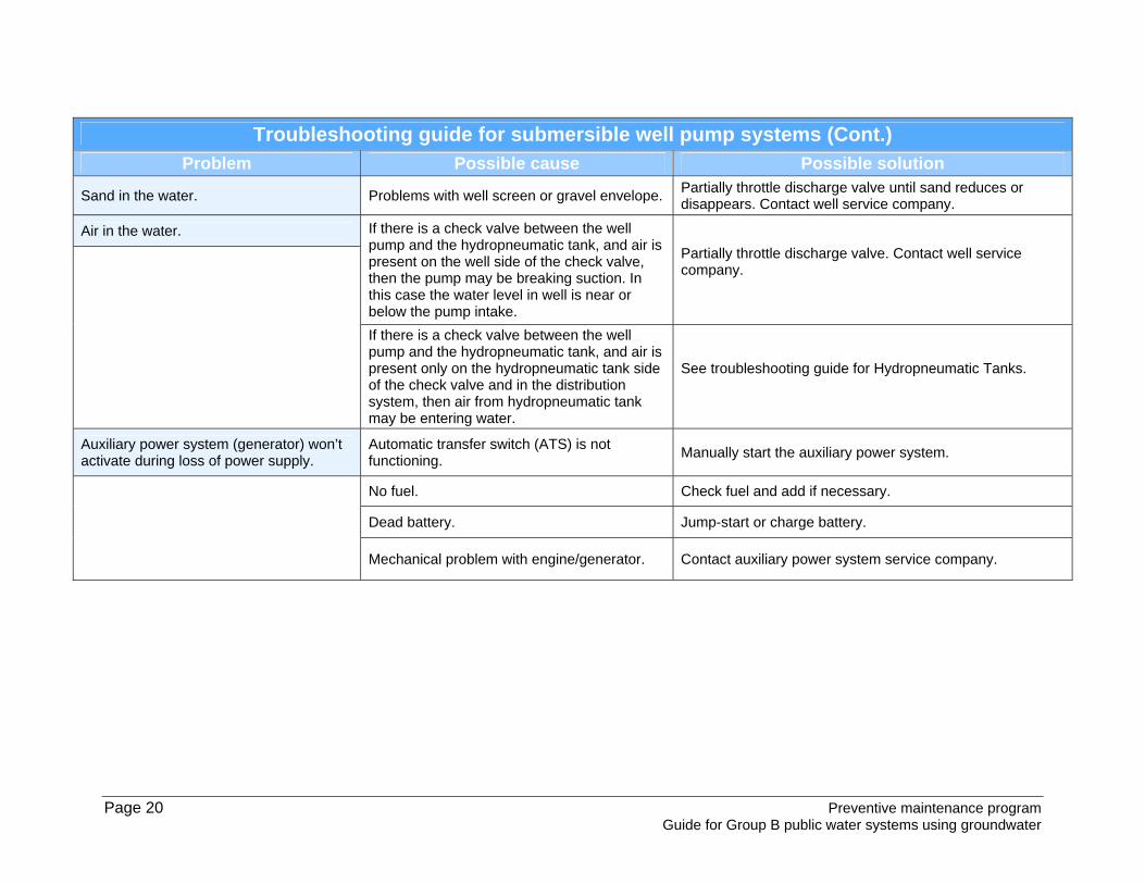
Troubleshooting guide for submersible well pump systems (Cont.) Problem Possible cause Possible solution
Sand in the water. Problems with well screen or gravel envelope. Partially throttle discharge valve until sand reduces or disappears. Contact well service company.
Air in the water. If there is a check valve between the well pump and the hydropneumatic tank, and air is present on the well side of the check valve, then the pump may be breaking suction. In this case the water level in well is near or below the pump intake.
Partially throttle discharge valve. Contact well service company.
If there is a check valve between the well pump and the hydropneumatic tank, and air is present only on the hydropneumatic tank side of the check valve and in the distribution system, then air from hydropneumatic tank may be entering water.
See troubleshooting guide for Hydropneumatic Tanks.
Auxiliary power system (generator) won’t activate during loss of power supply.
Automatic transfer switch (ATS) is not functioning.
Manually start the auxiliary power system.
No fuel. Check fuel and add if necessary.
Dead battery. Jump-start or charge battery.
Mechanical problem with engine/generator. Contact auxiliary power system service company.

Preventive maintenance program Page 21 Guide for Group B public water systems using groundwater
Troubleshooting guide for pressure tanks
Problem Possible cause Possible solution
Well pump won’t start. Circuit breaker or overload relay tripped. Reset breaker or manual overload relay.
Fuse burned out. Check for cause and correct, replace fuse(s).
No power to switch box. Check incoming power supply. Contact power company.
Short, broken, or loose wire.
Check for shorts and correct, tighten terminals, replace broken wires.
Low voltage.
Check incoming line voltage. Contact power company if low.
Failed motor. Contact electrical contractor.
Defective pressure switch.
Check voltage of incoming electric supply with pressure switch closed. Contact power company if voltage low. Perform maintenance on switch if voltage normal.
Well pump won’t shut off.
Defective pressure switch.
Refer to troubleshooting guide on Pumps and Pumping Facilities. Note: If the water supply pump is running constantly, excessive pressures can develop in the hydropneumatic tank and distribution system. The tank should be equipped with a pressure relief valve that opens at about 100 psi. This may protect the tank from damage but it is possible that the distribution system could be damaged if pressures exceed normal working pressures. Contact electrician experienced with industrial controls.
Cut-off pressure setting too high. Same as above.
Float switch or pressure transducer not functioning.
Same as above.
Well pump starts and stops too frequently (excessive cycle rate).
Leaking foot valve or check valve. Contact well specialist.
Defective pressure switch or automatic control system. High- or low-pressure cutoff switches may need adjustment.
Contact well specialist or electrician.

Page 22 Preventive maintenance program Guide for Group B public water systems using groundwater
Troubleshooting guide for pressure tanks (Cont.)
Problem Possible cause Possible solution
Excessive water use or major leak in water distribution system.
Locate and repair leak.
Water-logged hydropneumatic tank.
Check air-to-water ratio from sight tube (if provided). If the tube is completely filled with water or if the water level exceeds ⅔ of the volume of the tank, then air will have to be introduced into the tank. Check tank and air system for leaks. The optimum air-to-water ratio in the hydropneumatic tank should be ⅔ water to ⅓ air. If the problem persists or there is no sight tube, contact water system specialist.
Air-logged hydropneumatic tank.
Check air-to-water ratio from sight tube (if provided). If the tube is completely filled with air or if the water level is less than ½ the volume of the tank, then air will have to be bled from the tank. The optimum air-to-water ratio should be ⅔ water to ⅓ air. If the problem persists or there is no sight tube, contact water system specialist.
Sand or sediment in the water. Problems with well screen or gravel envelope. Contact well contractor.
If there is iron or manganese in the well water and it is not removed before the hydropneumatic tank, and the air in the hydropneumatic tank comes into direct contact with the water in the tank, then the iron and manganese could be oxidizing and settling in the tank. Also, sediment could be present in the distribution system.
Check air-to-water ratio from sight tube (if provided). If the tube is completely filled with air or the water level is less than ½ the volume of the tank, then air will have to be bled from the tank. The optimum air-to-water ratio should be ⅔ water to ⅓ air. If the problem persists or there is no sight tube, contact water system specialist. If there is a physical separation between the air and water in the tank, then the separator could have broken. Contact water system specialist.
Air in the water. If there is a check valve between the well pump and the hydropneumatic tank, and air is present on the well side of the check valve, then the pump may be breaking suction. In this case, the water level in well is near or below the pump intake.
Partially throttle discharge valve. Contact well service company.
Preventive maintenance program Page 23 Guide for Group B public water systems using groundwater
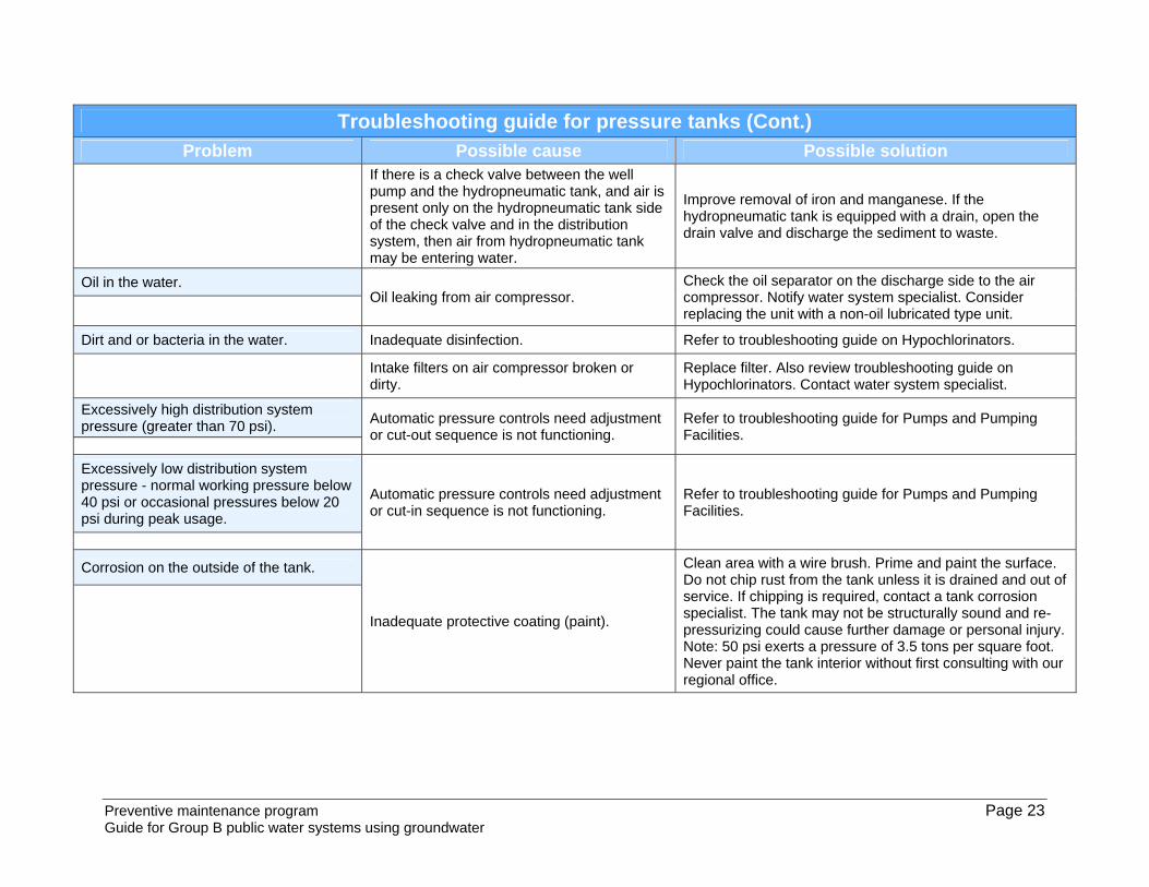
Troubleshooting guide for pressure tanks (Cont.)
Problem Possible cause Possible solution
If there is a check valve between the well pump and the hydropneumatic tank, and air is present only on the hydropneumatic tank side of the check valve and in the distribution system, then air from hydropneumatic tank may be entering water.
Improve removal of iron and manganese. If the hydropneumatic tank is equipped with a drain, open the drain valve and discharge the sediment to waste.
Oil in the water. Oil leaking from air compressor.
Check the oil separator on the discharge side to the air compressor. Notify water system specialist. Consider replacing the unit with a non-oil lubricated type unit.
Dirt and or bacteria in the water. Inadequate disinfection. Refer to troubleshooting guide on Hypochlorinators.
Intake filters on air compressor broken or dirty.
Replace filter. Also review troubleshooting guide on Hypochlorinators. Contact water system specialist.
Excessively high distribution system pressure (greater than 70 psi). Automatic pressure controls need adjustment
or cut-out sequence is not functioning. Refer to troubleshooting guide for Pumps and Pumping Facilities.
Excessively low distribution system pressure - normal working pressure below 40 psi or occasional pressures below 20 psi during peak usage.
Automatic pressure controls need adjustment or cut-in sequence is not functioning.
Refer to troubleshooting guide for Pumps and Pumping Facilities.
Corrosion on the outside of the tank.
Inadequate protective coating (paint).
Clean area with a wire brush. Prime and paint the surface. Do not chip rust from the tank unless it is drained and out of service. If chipping is required, contact a tank corrosion specialist. The tank may not be structurally sound and re-pressurizing could cause further damage or personal injury. Note: 50 psi exerts a pressure of 3.5 tons per square foot. Never paint the tank interior without first consulting with our regional office.

Page 24 Preventive maintenance program Guide for Group B public water systems using groundwater
Troubleshooting guide for pressure tanks (Cont.)
Problem Possible cause Possible solution
Tank is unstable and can easily be moved, or tank is supported by the piping.
Tank supports are inadequate.
Provide suitable and permanent supports so the tank can’t be moved and the piping is not supporting the weight of the tank. This may require taking the system out of service while these repairs are made. Never try to move a tank that is pressurized. Contact your water system specialist.

Preventive maintenance program Page 25 Guide for Group B public water systems using groundwater
Troubleshooting guide for storage facilities
Problem Possible cause Possible solution
Loss of disinfectant residual. Long detention time. Increase in temperature. Depletion of disinfectant from exposure to sunlight. Entry of chlorine demanding contaminants.
Cover reservoir. Reduce detention time with baffles, recirculation, inlet diffuser, mechanical mixer, pumps. Relocate inlet/outlet in tank. Size facility for more frequent turnover. Check screens on vents. Install bird wires and fences if necessary. Clean and disinfect storage facility.
Increase in heterotrophic plate count.
Loss of chlorine residual or contaminant entry.
Prevent loss of chlorine residual (see above) and rechlorinate storage tank. Check seals on hatches and screens on vents. Install bird wires and fences if necessary. Clean and disinfect storage facility.
Coliform bacteria occurrence. Loss of chlorine residual. Contaminant entry. Sediment or biofilm build-up
Check seals on hatches and screens on vents. Install bird wires and fences if necessary. Clean and disinfect storage facility.
Disinfection byproducts formation. Long detention time. Increase in pH or chlorine residual. Boosting chlorine. Organic matter contamination or algae growth.
Reduce detention time with baffles, recirculation, inlet diffuser, mechanical mixer, pumps. Relocate inlet/outlet in tank. Size facility for more frequent turnover. Look at alternative disinfectants.
Nitrification
Long detention time.
Reduce detention time with baffles, recirculation, inlet diffuser, mechanical mixer, pumps. Relocate inlet/outlet in tank. Increase turnover rate or size facility for more frequent turnover.
Sediment build-up Excess suspended materials, lime, iron or manganese in source water. Minimal velocities allowing depositions. Contaminant entry.
Improve influent water quality. Reduce detention time with baffles, recirculation, inlet diffuser, mechanical mixer, pumps. Avoid scouring. Inspect and clean tank more frequently.
Floating material or surface film. Build-up of iron or manganese sediments. Growth of iron or manganese forming bacteria.
Improve influent water quality. Avoid scouring. Inspect and clean tank more frequently.
Taste and odor complaints. Long detention time. Growth of algae or other organisms. Contaminant entry. Leaching from internal coatings or new concrete tank. Source water potential for taste and odor such as high levels of hydrogen sulfides.
Cover open reservoirs. Check seals on hatches and screens on vents. Install bird wires and fences if necessary. Improve influent water quality. Chlorinate. Flush distribution system. Clean and disinfect storage tank.

Page 26 Preventive maintenance program Guide for Group B public water systems using groundwater
Troubleshooting guide for storage facilities (Cont.)
Problem Possible cause Possible solution
Growth of algae or other biological organisms. Exposure to sunlight. Loss of chlorine
residual. Long detention time. Sediment or biofilm build-up.
Cover open reservoirs. Check seals on hatches and screens on vents. Install bird wires and fences if necessary. Improve influent water quality. Flush distribution system. Clean and disinfect storage tank.
Contaminant entry. Uncovered reservoirs or improper design of floating cover. Damaged or missing screens on vents and entry of bats, birds, rodents, or insects. Cross connection at drain or overflow.
Cover open reservoirs. Check seals on hatches and screens on vents. Install bird wires and fences if necessary. Flush distribution system. Clean and disinfect storage tank.
Increase in pH. Long detention time in concrete storage.
Provide coating on concrete walls. Increase turnover rate. Fluctuate water levels more frequently.
Biodegradation of internal coatings. Loss of chlorine residual allowing biological growth. Selection of wrong internal coating.
Prevent loss of chlorine residual. Chlorinate. Clean and disinfect storage tank.
Biofilm growth. Loss of chlorine residual. Nutrients from coatings or contaminants. Corrosion of surface promoting biological and algae growth. Bacterial seeding.
Prevent loss of chlorine residual. Chlorinate. Clean and disinfect storage tank. Flush distribution system.
Color. Decaying vegetative material. Algae growth in uncovered reservoirs. Sediment scouring. Iron or manganese.
Improve source water quality. Install treatment for iron and manganese. Increase cleaning frequency.
Red water. Metals uptake from metal surfaces from lack of or improper cathodic protection. Iron or manganese.
Provide proper corrosion treatment. Install or calibrate cathodic protection. Use sequestering agent. Apply coatings properly.
Build-up of iron and manganese. Iron and manganese in source water and long detention times. Oxidation and settling of iron or manganese. Improper sequestering agent dose.
Improve source water quality. Install or optimize sequestering system. Increase cleaning frequency.

Preventive maintenance program Page 27 Guide for Group B public water systems using groundwater
Troubleshooting guide for hypochlorination problems
Problem Possible cause Possible solution
Chemical feed pump won’t run. No power. Check to see if plug is securely in place. Ensure that there is power to the outlet and control systems.
Electrical problem with signal from well pump or flow sensor.
Check pump motor starter. Bypass flow sensor to determine if pump will operate manually. If you have a liquid level control, check the low-level cut-off switch. Repair or replace if necessary.
Motor failure. If the motor is cool and the power is on, the motor may have to be repaired or replaced. Check manufacturer’s information.
Motor overheating.
The motor is over-heated. The overload protection in the motor has opened. The motor will start again when it cools. Make sure that you have a proper voltage supply. Try to turn the motor shaft. If it does not turn, check for a binding pump mechanism.
Motor runs but diaphragm doesn’t move. The stroke adjustment may be set at zero. Reset stroke adjustment control knob.
The gear train may be stripped. Replace any defective parts.
Motor runs, diaphragm moves but no solution is pumped.
Solution tank may be empty. Check the solution level in the tank. If it is too low refill the tank.
The pump may not be primed. If not, prime it.
Suction line may have an air lock. Check the suction line for air locks. If there is an air lock, remove the anti-siphon spring from the discharge valve until the air lock is removed.
The fittings may be loose. Remove the fittings, clean off the old tape, put on new teflon tape, and replace FINGER tight.
Leaks from the pump housing. If there is solution dripping from the pump housing just behind the pump head, replace the diaphragm.

Page 28 Preventive maintenance program Guide for Group B public water systems using groundwater
Troubleshooting guide for hypochlorination problems (Cont.)
Problem Possible cause Possible solution
Motor runs, diaphragm moves but no solution is pumped. Valves and O-rings may be dirty.
Check the valves. Clean them if they are dirty. Replace the O-rings if they are damaged. Make sure they are well-seated.
Discharge line is blocked. Check the discharge line for kinks or blockages.
Abnormal noise. The chlorinator is probably mechanically damaged.
Check with your service representative. Switch operation to back up chlorinator.
Motor starts and stops. The motor may be overheating.
If it is, a thermal protection switch may be causing the start-stop action. Check with the service representative.
Low chlorine residual at point of entry. Improper procedure for running chlorine residual test or expired chemical reagents.
Check expiration date on chemical reagents. Check test procedure as described in test kit manual. Speed or stroke setting too low.
Pump not feeding an adequate quantity of chlorine.
Damaged diaphragm or suction leak.
Change in raw water quality. Test raw water for constituents that may cause increased chlorine demand, such as iron and manganese.
Pump air bound. Check foot valve.
Chlorine supply tank empty. Fill supply tank.
Reduced effectiveness of chlorine solution.
Check date that chlorine was received. Sodium hypochlorite solution may lose effectiveness after 30 days. If that is the case, the feed rate must be increased to obtain the desired residual.
Damaged suction or discharge lines (cracks or crimps).
Clean or repair lines with problems.
Connection at point of injection clogged or leaking.
Flush line and connection with mild acid such as acetic or muriatic. Replace any damaged parts that may be leaking.
Discharge line is blocked. Speed and stroke setting inadequate. Check manufacturer’s recommendations for proper settings to prime pump.
Suction lift too high due to feed pump relocation.
Check maximum suction lift for pump and relocate as necessary.

Preventive maintenance program Page 29 Guide for Group B public water systems using groundwater
Troubleshooting guide for hypochlorination problems (Cont.)
Problem Possible cause Possible solution
Discharge pressure too high. Check wellpump discharge pressure. Check pressure rating on chemical feed pump.
Suction fitting clogged. Clean or replace screen.
Trapped air in suction line. Ensure all fittings are tight.
Suction line not submerged in solution. Add chlorine solution to supply tank.
Loss of prime. Solution tank empty. Fill tank.
Air leaks in suction fittings. Check for cracked fittings.
Foot valve not in vertical position. Adjust foot valve to proper position.
Air trapped in suction tubing. Check connections and fittings.
Excessive chlorine residual at point of entry (POE).
Pump speed or stroke setting too high. Verify dose rate and calibrate pump to get desired dose.
Siphoning from solution tank. Ensure the 4-in-1 anti-siphon valve on chemical feed pump is operating properly.
Low well pump discharge pressure. Ensure well pump discharge pressure is at least 25 psi.
Failure to pump against pressure. Worn seal rings. Worn seal rings and cartridge valves may need to be replaced. Use spare parts kit.
Pumps maximum pressure rating to pump against may be exceeded by injection pressure.
Injection pressure cannot exceed the pump’s maximum pressure. See information plate on pump.
Ruptured diaphragm. Replace pump diaphragm.
Incorrect stroke length setting. Check zero on pump and re-zero pump. See manufacturer’s instructions.
Tubing run on discharge is too long.
Longer tubing runs may create friction loss sufficient to reduce the pump’s pressure rating. Consult manufacturer for more information.
Clogged foot valve strainer.
Remove foot valve strainer when pumping slurries or when solution particles cause the strainer to clog.
Page 30 Preventive maintenance program Guide for Group B public water systems using groundwater
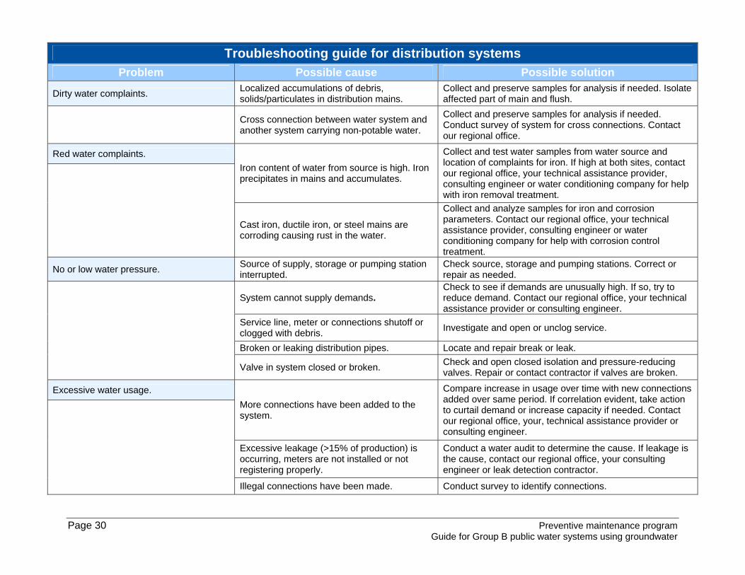
Troubleshooting guide for distribution systems
Problem Possible cause Possible solution
Dirty water complaints. Localized accumulations of debris, solids/particulates in distribution mains.
Collect and preserve samples for analysis if needed. Isolate affected part of main and flush.
Cross connection between water system and another system carrying non-potable water.
Collect and preserve samples for analysis if needed. Conduct survey of system for cross connections. Contact our regional office.
Red water complaints.
Iron content of water from source is high. Iron precipitates in mains and accumulates.
Collect and test water samples from water source and location of complaints for iron. If high at both sites, contact our regional office, your technical assistance provider, consulting engineer or water conditioning company for help with iron removal treatment.
Cast iron, ductile iron, or steel mains are corroding causing rust in the water.
Collect and analyze samples for iron and corrosion parameters. Contact our regional office, your technical assistance provider, consulting engineer or water conditioning company for help with corrosion control treatment.
No or low water pressure. Source of supply, storage or pumping station interrupted.
Check source, storage and pumping stations. Correct or repair as needed.
System cannot supply demands. Check to see if demands are unusually high. If so, try to reduce demand. Contact our regional office, your technical assistance provider or consulting engineer.
Service line, meter or connections shutoff or clogged with debris.
Investigate and open or unclog service.
Broken or leaking distribution pipes. Locate and repair break or leak.
Valve in system closed or broken. Check and open closed isolation and pressure-reducing valves. Repair or contact contractor if valves are broken.
Excessive water usage.
More connections have been added to the system.
Compare increase in usage over time with new connections added over same period. If correlation evident, take action to curtail demand or increase capacity if needed. Contact our regional office, your, technical assistance provider or consulting engineer.
Excessive leakage (>15% of production) is occurring, meters are not installed or not registering properly.
Conduct a water audit to determine the cause. If leakage is the cause, contact our regional office, your consulting engineer or leak detection contractor.
Illegal connections have been made. Conduct survey to identify connections.

Preventive maintenance program Page 31 Guide for Group B public water systems using groundwater
Troubleshooting guide for cross connections
Problem Possible cause Possible solution
Sudsy or soapy water. Hose connected to an unprotected hose bib with the other end in a bucket or sink of soapy water.
Equip all hose bibs with an Atmospheric Vacuum Breaker.
Positive coliform. Hose connected to an unprotected hose bib with the other end lying on the floor of the pump house, on the ground in the car wash area, in the wading or swimming pool or other nonpotable liquid.
Equip all hose bibs with an Atmospheric Vacuum Breaker.
Unprotected potable water line feeding a lawn irrigation system.
Install a backflow preventer on the potable water line feeding the irrigation system.
Submerged inlet, e.g. faucet submerged. Relocate faucet above flood level. Color in the water (unusual colors such as bright blue).
Backflow from toilet. Get help. Bring in someone who understands cross connections to evaluate your system.
Organic odors. Handheld pesticide/herbicide applicator attached to unprotected hose.
Don’t use these devices.

Page 32 Preventive maintenance program Guide for Group B public water systems using groundwater
Troubleshooting guide for sampling and monitoring
Problem Possible cause Possible solution
Positive total coliform. Improper sampling technique.
Check distribution system for low-pressure conditions, possibly due to line breaks or excessive flows that may result in a backflow problem.
Contamination entering distribution system. Ensure all staff are properly trained in sampling and transport procedures as described by lab procedures.
Inadequate chlorine residual at the sampling site.
Check the operation of the chlorination system. Refer to issues described in the chapter on pumps and hypochlorination systems. Ensure that residual test is performed properly.
Growth of biofilm in the distribution system. Thoroughly flush affected areas of the distribution system. Superchlorination may be necessary in severe cases.
Chlorine taste and odor.
High total chlorine residual and low free chlorine residual.
The free chlorine residual should be at least 85% of the total chlorine residual. Increase the chlorine dose rate to get past the breakpoint to destroy some of the combined residual that causes taste and odor problems. Additional system flushing may also be required.
Inability to maintain adequate free chlorine residual at the furthest points of the distribution system or at dead end lines.
Inadequate chlorine dose at treatment plant. Increase chlorine feed rate at point of application.
Problems with chlorine feed equipment. Check operation of chlorination equipment.
Ineffective distribution system flushing program.
Review distribution system flushing program and implement improvements to address areas of inadequate free chlorine residual.
Growth of biofilm in the distribution system. Increase flushing in area of biofilm problem.

Preventive maintenance program Guide for Group B public water systems using groundwater
Template: Create your own preventive maintenance program Table of responsibilities
Daily responsibilities
Task Primary SecondarySOP Reference
Primary means the name of the individual primarily responsible for completing this task Secondary means the name of the individual who will perform this task if the primary individual is unavailable SOP Reference means reference section to your standard operating procedure manual for your utility

Page 34 Preventive maintenance program Guide for small public water systems using groundwater
Weekly responsibilities
Task Primary SecondarySOP Reference
Primary means the name of the individual primarily responsible for completing this task Secondary means the name of the individual who will perform this task if the primary individual is unavailable SOP Reference means reference section to your standard operating procedure manual for your utility

Preventive maintenance program Guide for Group B public water systems using groundwater
Monthly responsibilities
Task Primary SecondarySOP Reference
Primary means the name of the individual primarily responsible for completing this task Secondary means the name of the individual who will perform this task if the primary individual is unavailable SOP Reference means reference section to your standard operating procedure manual for your utility

Page 36 Preventive maintenance program Guide for small public water systems using groundwater
Quarterly responsibilities
Task Primary SecondarySOP Reference
Primary means the name of the individual primarily responsible for completing this task Secondary means the name of the individual who will perform this task if the primary individual is unavailable SOP Reference means reference section to your standard operating procedure manual for your utility

Preventive maintenance program Guide for Group B public water systems using groundwater
Biannual responsibilities
Task Primary SecondarySOP Reference
Primary means the name of the individual primarily responsible for completing this task Secondary means the name of the individual who will perform this task if the primary individual is unavailable SOP Reference means reference section to your standard operating procedure manual for your utility

Page 38 Preventive maintenance program Guide for small public water systems using groundwater
Annual responsibilities
Task Primary SecondarySOP Reference
Primary means the name of the individual primarily responsible for completing this task Secondary means the name of the individual who will perform this task if the primary individual is unavailable SOP Reference means reference section to your standard operating procedure manual for your utility

Preventive maintenance program Guide for Group B public water systems using groundwater
As-needed responsibilities
Task Primary SecondarySOP Reference
Primary means the name of the individual primarily responsible for completing this task Secondary means the name of the individual who will perform this task if the primary individual is unavailable SOP Reference means reference section to your standard operating procedure manual for your utility