Embed Size (px)
Citation preview
TECHNICAL CATALOG
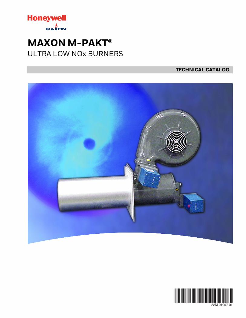
MAXON M-PAKT®ULTRA LOW NOx BURNERS
32M-01007-01
MAXON M-PAKT®
TABLE OF CONTENTS
Product description .................................................................................................................................. 3
Features and benefits .................................................................................................................................. 3
Typical emissions .................................................................................................................................. 3
Model Numbers .................................................................................................................................. 4
Specifications of M-PAKT® Burners .................................................................................................................................. 5
Materials of construction .................................................................................................................................. 6
Selection criteria .................................................................................................................................. 6
Dimensions .................................................................................................................................. 80.4M & 0.9M Packaged Burners - gas control method “S” ....................................... 81.5M, 2.5M and 3.0M Packaged Burners - gas control method “S” ......................... 9EB2 and EB3 (External Blower) Burners - gas control method “S” .......................... 10EB4, EB5, & EB6 (External Blower) Burners - gas control method “S” ................... 11EB7 (External Blower) Burners - gas control method “S” ........................................ 12Alternate gas control methods - gas control method “C” ......................................... 13Accessories and options .......................................................................................... 14
32M-01007—01 2 E - i - 4/16

MAXON M-PAKT®
PRODUCT DESCRIPTION
Typical MAXON quality and reliability is found in the M-PAKT® Ultra Low NOx Burners, which provide the world's lowest levels of NOx and CO. NOx is typically single digits in most applications. The M-PAKT® low NOx burner is suitable for industrial air heating for ovens and dryers for paint finishing, paper making, food baking, textile production, grain drying, and make-up air heating. M-PAKT® burners substantially reduce emissions in oxidizers, incinerators, heat exchangers and process heaters.
FEATURES AND BENEFITS
• Produces extremely low emissions of NOx and CO• Burns natural gas or propane• Flame contained almost entirely inside the dis-
charge sleeve• Compact packaged design with a variety of control
methods• Durable steel outer construction with stainless steel
internals
TYPICAL EMISSIONS
The M-PAKT® Ultra Low Emissions Burner produces NOx and CO emissions up to 95% less than conventional burners. Without exotic alloys or fragile ceramics, the burner reduces NOx with a patented, advanced flame stabilization. The M-PAKT® burner’s advanced anchoring of the flame reduces prompt NOx while thermal NOx is suppressed with an extremely uniform mixture.
In application, the M-PAKT® Ultra Low Emissions Burner produces single digit NOx corrected to 3% oxygen. In most installations, CO production is limited to extremely low levels. Exact emissions performance may vary in your application. Contact MAXON for information on installation specific estimates or guarantees. No guarantee of emissions is intended or implied without specific written guarantee from MAXON.
Factors that can affect emissions:• Process air direction, temperature and velocity• Process stream constituents, especially nitrogen bearing compounds• Combustion air quality, relative humidity and filtration• Burner location and installation• Fuel quality and heating value• Emissions instrument calibration and testing protocol
Application example of M-PAKT® gas burner
1) M-PAKT® Ultra Low NOx Burner
2) Pipe train con-structed for required codes and authori-ties
3) MAXON Shut-off Valves
4) Combustion air blower
5) System control panel
A typical air heater incorporating M-PAKT burners
1
4
3 3 2
5
E - i - 4/16 3 32M-01007—01

MAXON M-PAKT®
MODEL NUMBERS
A coded model number is provided on the nameplate of all M-PAKT® Burners to provide an instantaneous method to identify the configuration of the product. This model num-ber ensures accuracy in identifying your product, ordering replacement parts or communicating capabilities.
MODEL NO.
MAXON CORPORATIONMUNCIE, INDIANA U.S.A.
WWW.MAXONCORP.COM
SEE START UP INSTR.FOR FUEL SPECS.
AND PRESSURE REQ'D
MMBTUSIZE
S.O.#
M-PAKTULTRA LOW
U.S. PATENTS5735681, 5879148,8308477 & 8506287
EMISSIONSBURNER
R
R
Special(S if special, blank if not)
Burner type Size Blower Dischargesleeve
Mechanical gas control Switches Filter/
silencerFuture options
S MPB 1 1 R S F N AAA
Burner typeMPB - M-PAKT® burner
Size1 - 0.4M2 - 0.9M3 - 1.5M4 - 2.5M5 - 3.0MA - EB2B - EB3C - EB4D - EB5E - EB6F - EB7
Blower1 - 240/3/502 - 575/3/603 - 110/1/604 - None
Discharge sleeveR - RA330 stainless steel
Mechanical gas controlC - Honeywell ControLinksS - SMARTLINK MRVE - External control (EB only)
SwitchesF - None
Filter/silencerF - Filter onlyS - Filter/silencerN - None
32M-01007—01 4 E - i - 4/16
MAXON M-PAKT®
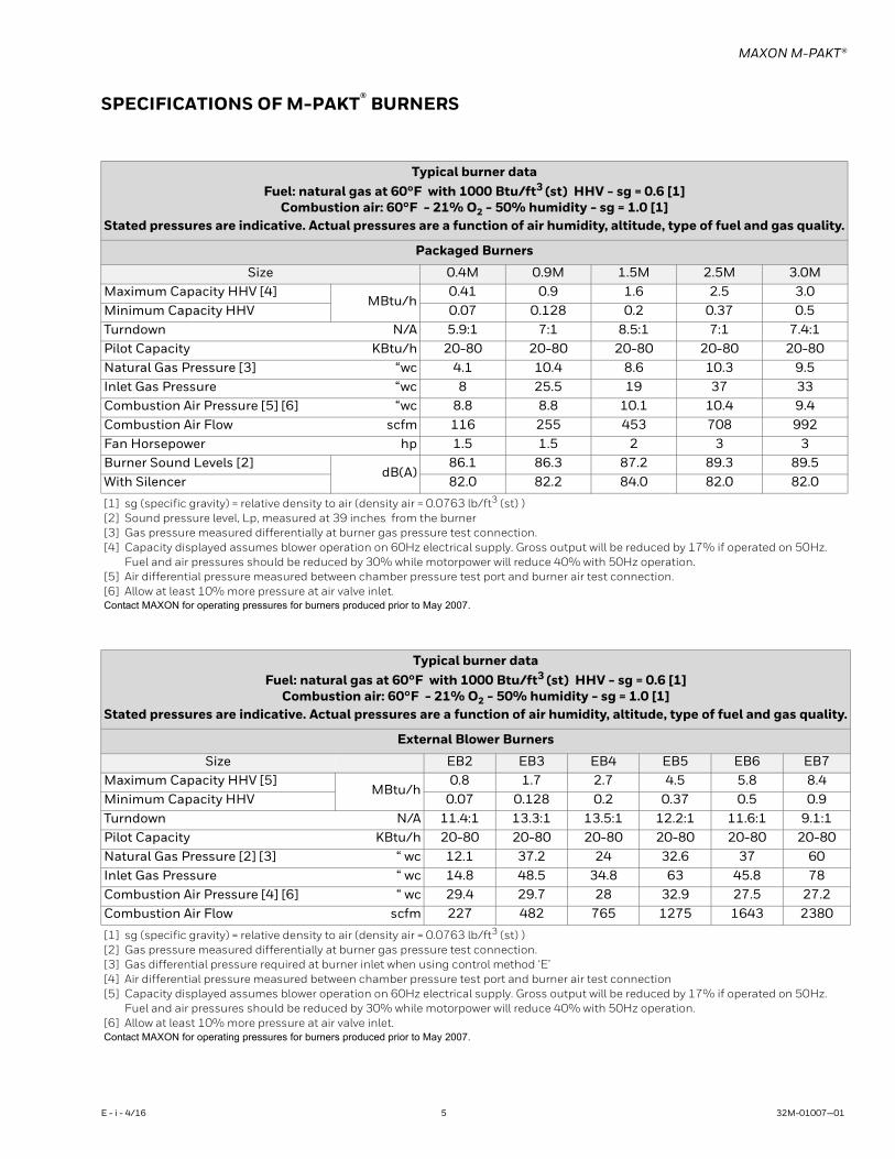
SPECIFICATIONS OF M-PAKT® BURNERS
Typical burner dataFuel: natural gas at 60°F with 1000 Btu/ft3 (st) HHV - sg = 0.6 [1]
Combustion air: 60°F - 21% O2 - 50% humidity - sg = 1.0 [1]Stated pressures are indicative. Actual pressures are a function of air humidity, altitude, type of fuel and gas quality.
Packaged Burners
Size 0.4M 0.9M 1.5M 2.5M 3.0MMaximum Capacity HHV [4]
MBtu/h0.41 0.9 1.6 2.5 3.0
Minimum Capacity HHV 0.07 0.128 0.2 0.37 0.5 Turndown N/A 5.9:1 7:1 8.5:1 7:1 7.4:1Pilot Capacity KBtu/h 20-80 20-80 20-80 20-80 20-80 Natural Gas Pressure [3] “wc 4.1 10.4 8.6 10.3 9.5 Inlet Gas Pressure “wc 8 25.5 19 37 33 Combustion Air Pressure [5] [6] “wc 8.8 8.8 10.1 10.4 9.4 Combustion Air Flow scfm 116 255 453 708 992 Fan Horsepower hp 1.5 1.5 2 3 3Burner Sound Levels [2]
dB(A)86.1 86.3 87.2 89.3 89.5
With Silencer 82.0 82.2 84.0 82.0 82.0
[1] sg (specific gravity) = relative density to air (density air = 0.0763 lb/ft3 (st) )[2] Sound pressure level, Lp, measured at 39 inches from the burner[3] Gas pressure measured differentially at burner gas pressure test connection.[4] Capacity displayed assumes blower operation on 60Hz electrical supply. Gross output will be reduced by 17% if operated on 50Hz.
Fuel and air pressures should be reduced by 30% while motorpower will reduce 40% with 50Hz operation.[5] Air differential pressure measured between chamber pressure test port and burner air test connection.[6] Allow at least 10% more pressure at air valve inlet.Contact MAXON for operating pressures for burners produced prior to May 2007.
Typical burner dataFuel: natural gas at 60°F with 1000 Btu/ft3 (st) HHV - sg = 0.6 [1]
Combustion air: 60°F - 21% O2 - 50% humidity - sg = 1.0 [1]Stated pressures are indicative. Actual pressures are a function of air humidity, altitude, type of fuel and gas quality.
External Blower Burners
Size EB2 EB3 EB4 EB5 EB6 EB7Maximum Capacity HHV [5]
MBtu/h0.8 1.7 2.7 4.5 5.8 8.4
Minimum Capacity HHV 0.07 0.128 0.2 0.37 0.5 0.9 Turndown N/A 11.4:1 13.3:1 13.5:1 12.2:1 11.6:1 9.1:1Pilot Capacity KBtu/h 20-80 20-80 20-80 20-80 20-80 20-80 Natural Gas Pressure [2] [3] “ wc 12.1 37.2 24 32.6 37 60 Inlet Gas Pressure “ wc 14.8 48.5 34.8 63 45.8 78 Combustion Air Pressure [4] [6] “ wc 29.4 29.7 28 32.9 27.5 27.2 Combustion Air Flow scfm 227 482 765 1275 1643 2380
[1] sg (specific gravity) = relative density to air (density air = 0.0763 lb/ft3 (st) )[2] Gas pressure measured differentially at burner gas pressure test connection.[3] Gas differential pressure required at burner inlet when using control method ‘E’[4] Air differential pressure measured between chamber pressure test port and burner air test connection[5] Capacity displayed assumes blower operation on 60Hz electrical supply. Gross output will be reduced by 17% if operated on 50Hz.
Fuel and air pressures should be reduced by 30% while motorpower will reduce 40% with 50Hz operation.[6] Allow at least 10% more pressure at air valve inlet.Contact MAXON for operating pressures for burners produced prior to May 2007.
E - i - 4/16 5 32M-01007—01
MAXON M-PAKT®
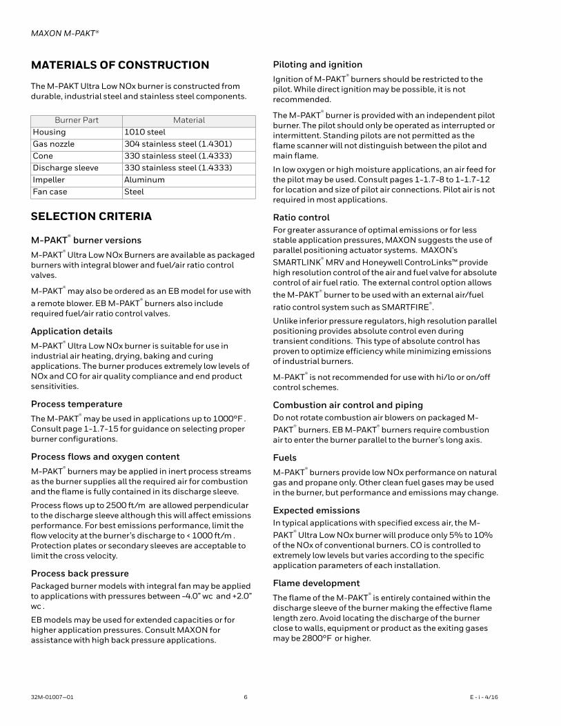
MATERIALS OF CONSTRUCTION
The M-PAKT Ultra Low NOx burner is constructed from durable, industrial steel and stainless steel components.
SELECTION CRITERIA
M-PAKT® burner versions
M-PAKT® Ultra Low NOx Burners are available as packaged burners with integral blower and fuel/air ratio control valves.
M-PAKT® may also be ordered as an EB model for use with a remote blower. EB M-PAKT® burners also include required fuel/air ratio control valves.
Application details
M-PAKT® Ultra Low NOx burner is suitable for use in industrial air heating, drying, baking and curing applications. The burner produces extremely low levels of NOx and CO for air quality compliance and end product sensitivities.
Process temperature
The M-PAKT® may be used in applications up to 1000°F . Consult page 1-1.7-15 for guidance on selecting proper burner configurations.
Process flows and oxygen content
M-PAKT® burners may be applied in inert process streams as the burner supplies all the required air for combustion and the flame is fully contained in its discharge sleeve.
Process flows up to 2500 ft/m are allowed perpendicular to the discharge sleeve although this will affect emissions performance. For best emissions performance, limit the flow velocity at the burner’s discharge to < 1000 ft/m . Protection plates or secondary sleeves are acceptable to limit the cross velocity.
Process back pressurePackaged burner models with integral fan may be applied to applications with pressures between -4.0” wc and +2.0” wc .
EB models may be used for extended capacities or for higher application pressures. Consult MAXON for assistance with high back pressure applications.
Piloting and ignition
Ignition of M-PAKT® burners should be restricted to the pilot. While direct ignition may be possible, it is not recommended.
The M-PAKT® burner is provided with an independent pilot burner. The pilot should only be operated as interrupted or intermittent. Standing pilots are not permitted as the flame scanner will not distinguish between the pilot and main flame.
In low oxygen or high moisture applications, an air feed for the pilot may be used. Consult pages 1-1.7-8 to 1-1.7-12 for location and size of pilot air connections. Pilot air is not required in most applications.
Ratio controlFor greater assurance of optimal emissions or for less stable application pressures, MAXON suggests the use of parallel positioning actuator systems. MAXON’s SMARTLINK® MRV and Honeywell ControLinks™ provide high resolution control of the air and fuel valve for absolute control of air fuel ratio. The external control option allows the M-PAKT® burner to be used with an external air/fuel ratio control system such as SMARTFIRE®.
Unlike inferior pressure regulators, high resolution parallel positioning provides absolute control even during transient conditions. This type of absolute control has proven to optimize efficiency while minimizing emissions of industrial burners.
M-PAKT® is not recommended for use with hi/lo or on/off control schemes.
Combustion air control and pipingDo not rotate combustion air blowers on packaged M-PAKT® burners. EB M-PAKT® burners require combustion air to enter the burner parallel to the burner’s long axis.
Fuels
M-PAKT® burners provide low NOx performance on natural gas and propane only. Other clean fuel gases may be used in the burner, but performance and emissions may change.
Expected emissionsIn typical applications with specified excess air, the M-PAKT® Ultra Low NOx burner will produce only 5% to 10% of the NOx of conventional burners. CO is controlled to extremely low levels but varies according to the specific application parameters of each installation.
Flame development
The flame of the M-PAKT® is entirely contained within the discharge sleeve of the burner making the effective flame length zero. Avoid locating the discharge of the burner close to walls, equipment or product as the exiting gases may be 2800°F or higher.
Burner Part MaterialHousing 1010 steelGas nozzle 304 stainless steel (1.4301)Cone 330 stainless steel (1.4333)Discharge sleeve 330 stainless steel (1.4333)Impeller AluminumFan case Steel
32M-01007—01 6 E - i - 4/16
MAXON M-PAKT®
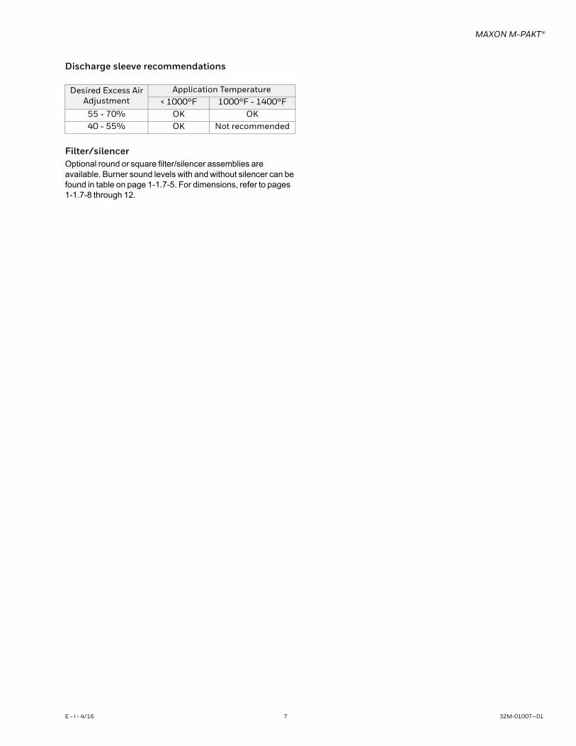
Discharge sleeve recommendations
Filter/silencerOptional round or square filter/silencer assemblies are available. Burner sound levels with and without silencer can be found in table on page 1-1.7-5. For dimensions, refer to pages 1-1.7-8 through 12.
Desired Excess AirAdjustment
Application Temperature< 1000°F 1000°F - 1400°F
55 - 70% OK OK40 - 55% OK Not recommended
E - i - 4/16 7 32M-01007—01

MAXON M-PAKT®
DIMENSIONS
0.4M & 0.9M Packaged Burners - gas control method “S”
1) 1/8” NPT com-bustion air pressure test port
2) Observation port
3) Gas pressure test port
4) 1/4” NPT pilot gas inlet
5) Air pressure switch connec-tion
6) Chamber pressure test port
7) Spark ignitor
8) Flame scanner connection 1” NPT-F
9) Gas inlet 0.4M - 1/2” NPT (F) 0.9M - 3/4” NPT (F)
View A-A View B-B
ABC
1
9
2
HØ IØ J
3
4
E
4X G
4X F
A-A B-B
K
L
Ø P
O
5
N
8
S
7
TE
Q6
Dimensions in inches unless stated otherwiseA B C D E F G slot H square I Ø J Ø
40.19 12.5 17.32 5.47 23.29 45° 0.62 15.5 20.25 17.5
Dimensions in inches unless stated otherwiseK L M N O P Ø Q S T
52.2 28.75 26.9 3.25 16.44 10.4 4.6 28.0 24.5
32M-01007—01 8 E - i - 4/16
MAXON M-PAKT®
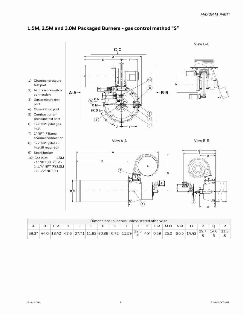
1.5M, 2.5M and 3.0M Packaged Burners - gas control method “S”
1) Chamber pressure test port
2) Air pressure switch connection
3) Gas pressure test port
4) Observation port
5) Combustion air pressure test port
6) 1/4” NPT pilot gas inlet
7) 1” NPT-F flame scanner connection
8) 1/2” NPT pilot air inlet (if required)
9) Spark ignitor
10) Gas inlet 1.5M - 1” NPT (F) 2.5M - 1-1/4” NPT (F) 3.0M - 1-1/2” NPT (F)
View C-C
View A-A View B-B
Dimensions in inches unless stated otherwiseA B C Ø D E F G H I J K L Ø M Ø N Ø O P Q R
69.37 44.0 18.42 42.6 27.71 11.83 30.86 6.72 11.59 22.5° 45° 0.59 25.0 26.5 14.42 29.7
8 14.6
5 31.3
8
DE F
C-C
B-BA-AØ N
Ø M
8X Ø L
K
J I
3
4
5
6
7
8
10
S
C
A
B
2
Ø C
1
R
GP
O
H
9
Q
E - i - 4/16 9 32M-01007—01
MAXON M-PAKT®
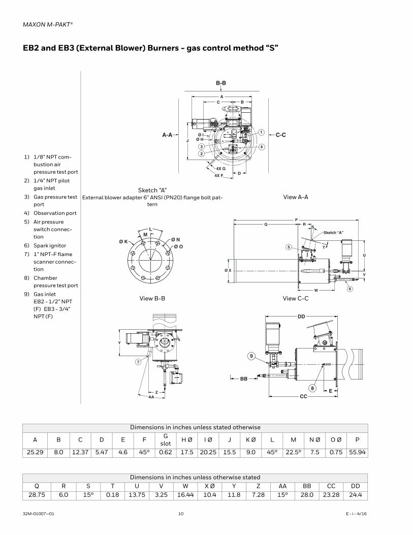
EB2 and EB3 (External Blower) Burners - gas control method “S”
1) 1/8” NPT com-bustion air pressure test port
2) 1/4” NPT pilot gas inlet
3) Gas pressure test port
4) Observation port
5) Air pressure switch connec-tion
6) Spark ignitor
7) 1” NPT-F flame scanner connec-tion
8) Chamber pressure test port
9) Gas inlet EB2 - 1/2” NPT (F) EB3 - 3/4” NPT (F)
Sketch “A”External blower adapter 6” ANSI (PN20) flange bolt pat-
ternView A-A
View B-B View C-C
Dimensions in inches unless stated otherwise
A B C D E F Gslot H Ø I Ø J K Ø L M N Ø O Ø P
25.29 8.0 12.37 5.47 4.6 45° 0.62 17.5 20.25 15.5 9.0 45° 22.5° 7.5 0.75 55.94
Dimensions in inches unless otherwise statedQ R S T U V W X Ø Y Z AA BB CC DD
28.75 6.0 15° 0.18 13.75 3.25 16.44 10.4 11.8 7.28 15° 28.0 23.28 24.4
B-B
C-CA-A
AC B
JØ I
Ø H
4X G
4X F D
3
2
1
4
Ø K
LM
Ø NØ O
PQ R
S
5
Sketch “A”
T
U
V
6W
Ø X
Y
7
ZAA
DD
BB
CCE8
9
32M-01007—01 10 E - i - 4/16
MAXON M-PAKT®
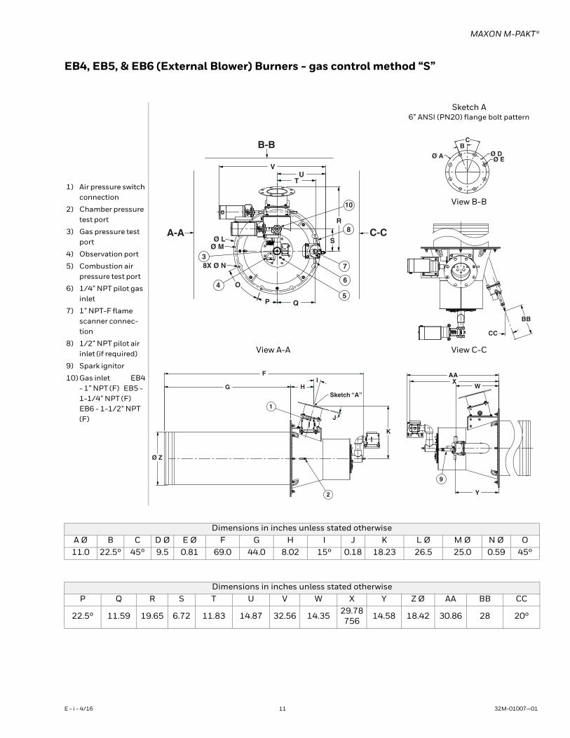
EB4, EB5, & EB6 (External Blower) Burners - gas control method “S”
1) Air pressure switch connection
2) Chamber pressure test port
3) Gas pressure test port
4) Observation port
5) Combustion air pressure test port
6) 1/4” NPT pilot gas inlet
7) 1” NPT-F flame scanner connec-tion
8) 1/2” NPT pilot air inlet (if required)
9) Spark ignitor
10) Gas inlet EB4 - 1” NPT (F) EB5 - 1-1/4” NPT (F) EB6 - 1-1/2” NPT (F)
Sketch A6” ANSI (PN20) flange bolt pattern
View B-B
View A-A View C-C
Dimensions in inches unless stated otherwiseA Ø B C D Ø E Ø F G H I J K L Ø M Ø N Ø O11.0 22.5° 45° 9.5 0.81 69.0 44.0 8.02 15° 0.18 18.23 26.5 25.0 0.59 45°
Dimensions in inches unless stated otherwiseP Q R S T U V W X Y Z Ø AA BB CC
22.5° 11.59 19.65 6.72 11.83 14.87 32.56 14.35 29.78 756 14.58 18.42 30.86 28 20°
B-B
C-CA-A
VU
T
R
S
10
8
7
6
5QP
O
Ø LØ M
8X Ø N3
4
Ø A
BC
Ø DØ E
BB
CC
F
G HI
Sketch “A”
J
K
2
1
Ø Z
AAX
W
Y
9
E - i - 4/16 11 32M-01007—01
MAXON M-PAKT®
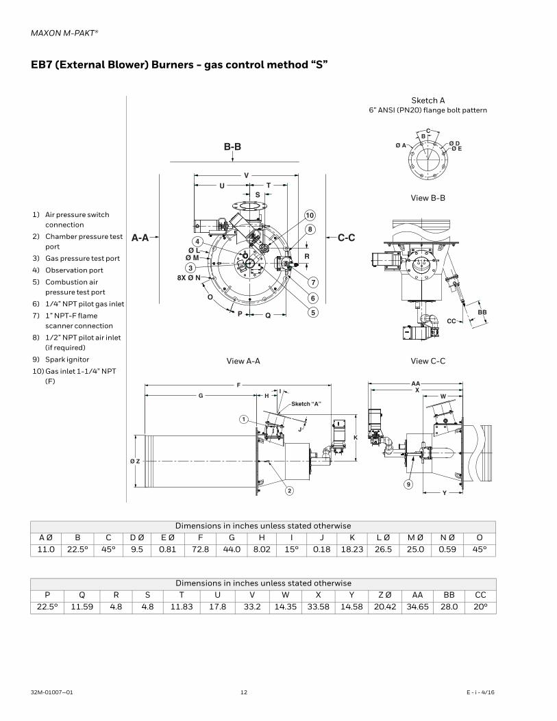
EB7 (External Blower) Burners - gas control method “S”
1) Air pressure switch connection
2) Chamber pressure test port
3) Gas pressure test port
4) Observation port
5) Combustion air pressure test port
6) 1/4” NPT pilot gas inlet
7) 1” NPT-F flame scanner connection
8) 1/2” NPT pilot air inlet (if required)
9) Spark ignitor
10) Gas inlet 1-1/4” NPT (F)
Sketch A6” ANSI (PN20) flange bolt pattern
View B-B
View A-A View C-C
Dimensions in inches unless stated otherwiseA Ø B C D Ø E Ø F G H I J K L Ø M Ø N Ø O11.0 22.5° 45° 9.5 0.81 72.8 44.0 8.02 15° 0.18 18.23 26.5 25.0 0.59 45°
Dimensions in inches unless stated otherwiseP Q R S T U V W X Y Z Ø AA BB CC
22.5° 11.59 4.8 4.8 11.83 17.8 33.2 14.35 33.58 14.58 20.42 34.65 28.0 20°
B-B
C-CA-A
VU T
S
R
QP
O
10
8
7
6
5
3
4
8X Ø N
Ø LØ M
Ø A
BC
Ø DØ E
BBCC
Ø Z
G
F
HI
Sketch “A”
JK
1
2
AAX
W
Y9
32M-01007—01 12 E - i - 4/16
MAXON M-PAKT®
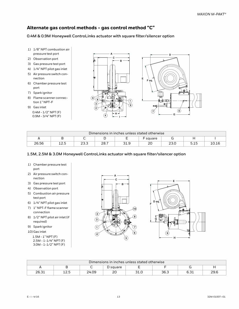
Alternate gas control methods - gas control method “C”
0.4M & 0.9M Honeywell ControLinks actuator with square filter/silencer option
1.5M, 2.5M & 3.0M Honeywell ControLinks actuator with square filter/silencer option
1) 1/8” NPT combustion air pressure test port
2) Observation port
3) Gas pressure test port
4) 1/4” NPT pilot gas inlet
5) Air pressure switch con-nection
6) Chamber pressure test port
7) Spark ignitor
8) Flame scanner connec-tion 1” NPT-F
9) Gas inlet
0.4M - 1/2” NPT (F) 0.9M - 3/4” NPT (F)
A
CB
IH
1
9
68
3
2
4 G7 6
EF sq.
D
Dimensions in inches unless stated otherwiseA B C D E F square G H I
26.56 12.5 23.3 28.7 31.9 20 23.0 5.15 10.16
1) Chamber pressure test port
2) Air pressure switch con-nection
3) Gas pressure test port
4) Observation port
5) Combustion air pressure test port
6) 1/4” NPT pilot gas inlet
7) 1” NPT-F flame scanner connection
8) 1/2” NPT pilot air inlet (if required)
9) Spark ignitor
10) Gas inlet
1.5M - 1” NPT (F) 2.5M - 1-1/4” NPT (F) 3.0M - 1-1/2” NPT (F)
A
C
B
10
8
7
6
5
4
1
3
2
E
FD sq.
G
H
9
Dimensions in inches unless stated otherwiseA B C D square E F G H
26.31 12.5 24.09 20 31.0 36.3 6.31 29.6
E - i - 4/16 13 32M-01007—01
MAXON M-PAKT®
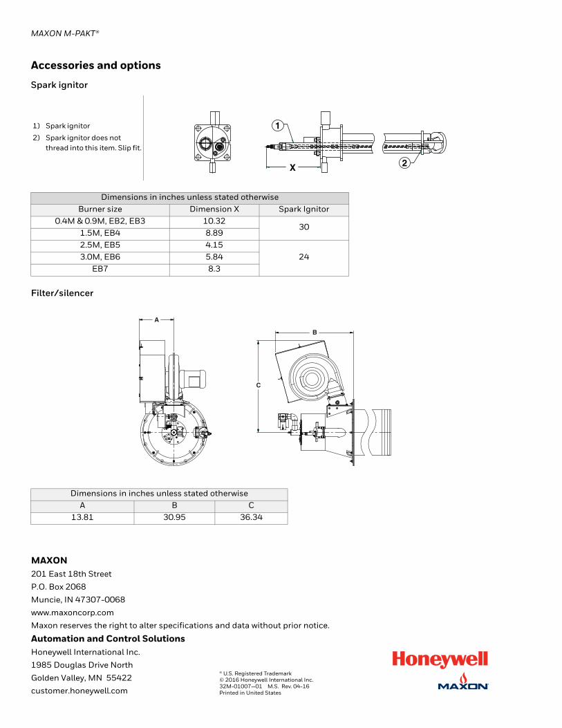
Accessories and options
Spark ignitor
Filter/silencer
1) Spark ignitor
2) Spark ignitor does not thread into this item. Slip fit.
Dimensions in inches unless stated otherwiseBurner size Dimension X Spark Ignitor
0.4M & 0.9M, EB2, EB3 10.32 30
1.5M, EB4 8.89 2.5M, EB5 4.15
24 3.0M, EB6 5.84 EB7 8.3
Dimensions in inches unless stated otherwiseA B C
13.81 30.95 36.34
1
2X
A
B
C
MAXON201 East 18th Street
P.O. Box 2068
Muncie, IN 47307-0068
www.maxoncorp.com
Maxon reserves the right to alter specifications and data without prior notice.
Automation and Control SolutionsHoneywell International Inc.
1985 Douglas Drive North
Golden Valley, MN 55422
customer.honeywell.com
® U.S. Registered Trademark© 2016 Honeywell International Inc.32M-01007—01 M.S. Rev. 04-16Printed in United States