Embed Size (px)
Citation preview
32-Channel Head Coil Array for Highly Accelerated Parallel Imaging Applications
H. E. Cline1, D. K. Sodikson2, T. Niendorf3, R. Giaquinto1 1Global Research Center, General Electric, Niskayuna, NY, United States, 2Beth Isreal Deaconess Medical Center, Harvard Medical
School, Boston, MA, United States, 3Medical Systems, General Electric, Waukesha, WI, United States
Introduction The tradeoff between available signal-to-noise ratio (SNR) and achievable acceleration factor represents a fundamental challenge in clinical parallel imaging applications. The use of large numbers of array elements can improve SNR at modest accelerations and can allow access to high accelerations, but careful design is required to avoid excessive circuit-related losses. This study is aimed at the design of a 32-channel array that is tailored for multidimensional parallel imaging applications in the brain. Array performance was examined in volunteer studies using high spatial resolution anatomical T1 and T2 weighted imaging in conjunction with as much as order-of-magnitude accelerations.
0.02 0 0.02 0.04
xn 0, xn 1,,
0 5 10 153 .10
8
2 .108
1 .108
0
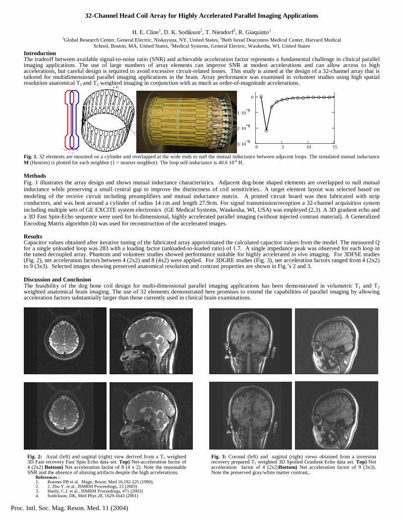
v Fig. 1. 32 elements are mounted on a cylinder and overlapped at the wide ends to null the mutual inductance between adjacent loops. The simulated mutual inductance M (Henries) is plotted for each neighbor (1 = nearest neighbor). The loop self-inductance is 40.6 10-8 H.
Methods Fig. 1 illustrates the array design and shows mutual inductance characteristics. Adjacent dog-bone shaped elements are overlapped to null mutual inductance while preserving a small central gap to improve the distinctness of coil sensitivities.. A target element layout was selected based on modeling of the receive circuit including preamplifiers and mutual inductance matrix. A printed circuit board was then fabricated with strip conductors, and was bent around a cylinder of radius 14 cm and length 27.9cm. For signal transmission/reception a 32-channel acquisition system including multiple sets of GE EXCITE system electronics (GE Medical Systems, Waukesha, WI, USA) was employed (2,3). A 3D gradient echo and a 3D Fast Spin-Echo sequence were used for bi-dimensional, highly accelerated parallel imaging (without injected contrast material). A Generalized Encoding Matrix algorithm (4) was used for reconstruction of the accelerated images.
Results Capacitor values obtained after iterative tuning of the fabricated array approximated the calculated capacitor values from the model. The measured Q for a single unloaded loop was 283 with a loading factor (unloaded-to-loaded ratio) of 1.7. A single impedance peak was observed for each loop in the tuned decoupled array. Phantom and volunteer studies showed performance suitable for highly accelerated in vivo imaging. For 3DFSE studies (Fig. 2), net acceleration factors between 4 (2x2) and 8 (4x2) were applied. For 3DGRE studies (Fig. 3), net acceleration factors ranged from 4 (2x2) to 9 (3x3). Selected images showing preserved anatomical resolution and contrast properties are shown in Fig.’s 2 and 3. Discussion and Conclusion The feasibility of the dog bone coil design for multi-dimensional parallel imaging applications has been demonstrated in volumetric T1 and T2 weighted anatomical brain imaging. The use of 32 elements demonstrated here promises to extend the capabilities of parallel imaging by allowing acceleration factors substantially larger than those currently used in clinical brain examinations.
Fig. 2: Axial (left) and sagittal (right) view derived from a T2 weighted 3D Fast recovery Fast Spin Echo data set. Top) Net-acceleration factor of 4 (2x2) Bottom) Net acceleration factor of 8 (4 x 2). Note the reasonable SNR and the absence of aliasing artifacts despite the high accelerations.
Fig. 3: Coronal (left) and sagittal (right) views obtained from a inversion recovery prepared T1 weighted 3D Spoiled Gradient Echo data set. Top) Net acceleration factor of 4 (2x2)Bottom) Net acceleration factor of 9 (3x3). Note the preserved gray/white matter contrast,.
References : 1. Roemer PB et al. Magn. Reson. Med 16,192-225 (1990), 2. 2. Zhu Y. et al., ISMRM Proceedings, 22 (2003) 3. Hardy, C.J. et al., ISMRM Proceedings, 471 (2003) 4. Sodickson, DK, Med Phys 28, 1629-1643 (2001)
Proc. Intl. Soc. Mag. Reson. Med. 11 (2004)