Embed Size (px)
Citation preview
70
CHAPTER 3
Strengthening of Reinforced Concrete
Structure Elements Using Concrete Jackets
3.1.Introduction
Repairing of reinforced concrete elements is required after a damage.
Strengthening such elements is a method to increase the earthquake resistance. Thus,
the strength of the structures can be moderately or significantly increased and the
ductility can be improved.
Depending on the desired earthquake resistance, the level of the damage, the
type of the elements and their connections, members can be repaired and / or
strengthened by injection, removal and replacement of damaged parts or jacketing.
For repair of concrete structures the advice of engineers is required.
Establishing bonds between old and new concrete is of importance. It can be
done by chipping away the concrete cover of the original member and roughening its
surface, by preparing the surface with glue (for instance, with epoxy prior to
concreting), by additional welding of reinforcement or by formation of reinforced
concrete or steel dowels.
Perfect confinement by close, adequate and appropriately shaped stirrups and
ties contributes to the improvement of the ductility of the strengthened members.
Redistribution of the internal force in structures due to member stiffness changes is
very important.
Jacketing with steel profiles (angles and straps) is used for the strengthening of
columns. The beam – to – column joint is difficult to be strengthen in this way.
Jacketing by steel encasement is implemented by gluing of steel plates on the

71
external surfaces of the original members. Steel plates as reinforcement are glued to
the concrete by epoxy resin. This does not require any demolition, it is easy to
implement and hardly increase the cross section of the members. Trained technicians
are required for this work.
Jacketing by steel profiles or encasement requires special measures for fire and
corrosion protection of the new steel profiles. Reinforced concrete jacketing does not
need such a protection but the construction procedure is more difficult.
3.2. Strengthening of Reinforced Concrete Columns :-
Increasing flexural and shear strength, improving column ductility and
rearrangement of column stiffness can be achieved by repairing techniques.
Column flexural strength increases with the enlargement of the concrete area
and by adding reinforcement. Shear strength, and especially ductility, is improved by
closely placed reinforcement ties (steal strips).
Damage to reinforced concrete columns, may include slight cracks (horizontal
or diagonal) without damage to reinforcement, superficial damage in the concrete
without damage to reinforcement, crushing of the concrete, buckling of reinforcement
or rupture of ties. Based on the degree of damage, techniques such as injections,
removal and replacement or jacketing can be applied.
3.2.1.Local Repairs
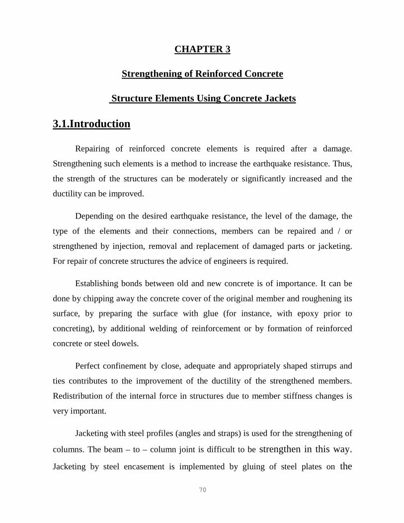
Resin injections are applied only for damage columns with slight cracks
without damaged concrete or reinforcement. Epoxy resin injection is suitable for
cracks with width from 0.1 to 5 mm. cement grout injections can be applied for larger
cracks (widths from 2 to 5 mm) (Figure 3.1).
Removal and replacement is necessary for heavily damaged columns with
crushed concrete, buckled longitudinal bars or ruptured ties.
72
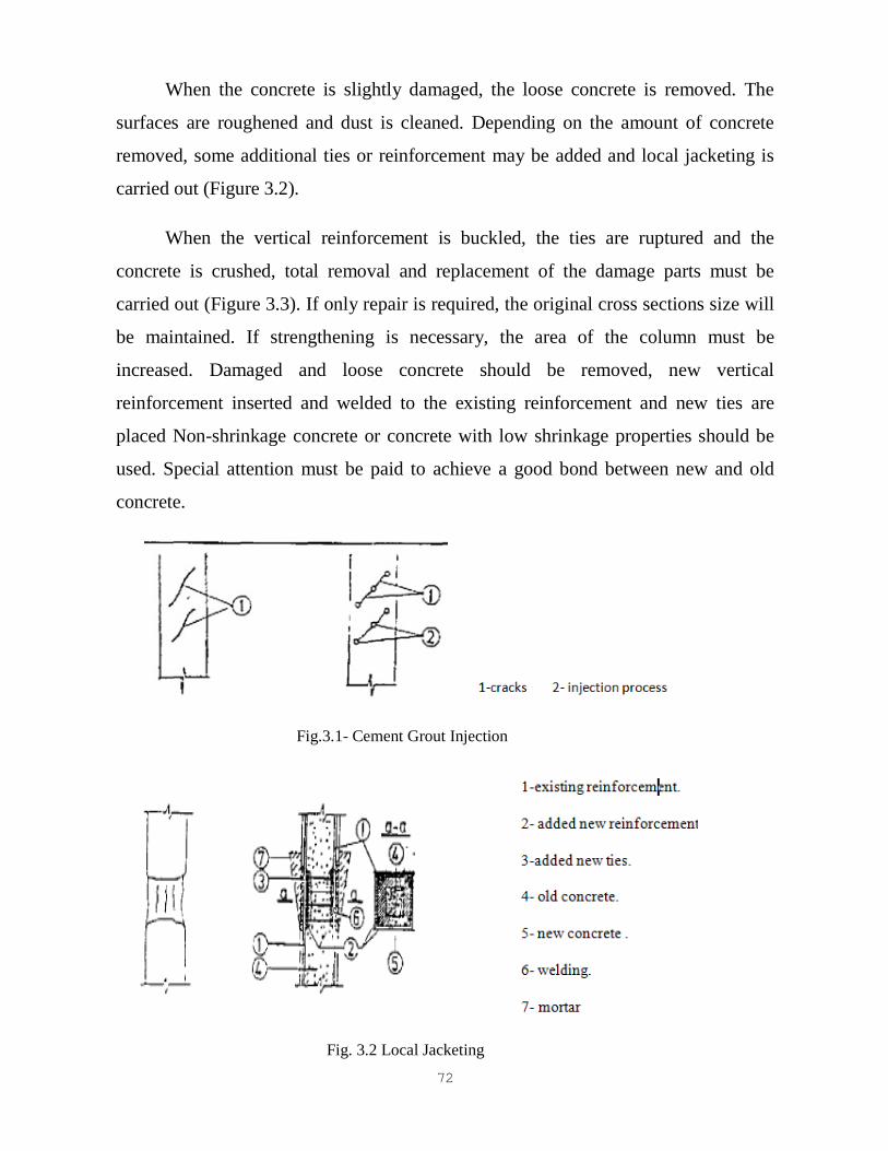
When the concrete is slightly damaged, the loose concrete is removed. The
surfaces are roughened and dust is cleaned. Depending on the amount of concrete
removed, some additional ties or reinforcement may be added and local jacketing is
carried out (Figure 3.2).
When the vertical reinforcement is buckled, the ties are ruptured and the
concrete is crushed, total removal and replacement of the damage parts must be
carried out (Figure 3.3). If only repair is required, the original cross sections size will
be maintained. If strengthening is necessary, the area of the column must be
increased. Damaged and loose concrete should be removed, new vertical
reinforcement inserted and welded to the existing reinforcement and new ties are
placed Non-shrinkage concrete or concrete with low shrinkage properties should be
used. Special attention must be paid to achieve a good bond between new and old
concrete.
Fig.3.1- Cement Grout Injection
Fig. 3.2 Local Jacketing

73
Fig. 3.3 Removal and placement of damaged parts
3.2.2.Reinforced Concrete Jacketing for Column
Jacketing should be applied in cases of heavy damage columns or in cases of
insufficient column strength. This is really a strengthening procedure although, but it
can also be used for repairing. Jacketing can be performed by adding reinforced
concrete, steel profiles or steel encasement.
Reinforced concrete jacketing, depending on the space around the column, can
be adding jacketing to one, two, three or four sides of the column (Figure 3.4). It is
recommended that columns be jacketed on all four sides. In order to achieve the best
bond between new and existing concrete, four-sided jacketing is best. In case one,
two or three sided jacketing is all that is possible, the concrete cover in the jacketed
parts of the existing column must be chipped away so that new ties can be welded to
existing ties. In case of a four-sided jacketing, only roughening of the surface of the
existing column may be required.
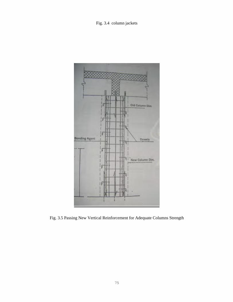
Jacketing only within one floor does not improve seismic response unless shear
walls are also added. Adequate column strength can be achieved by passing the new
vertical reinforcement through holes drilled in the slab and adding new concrete in
the beam-column joint region (Figure 3.5) special attention should be paid to the
good confinement of the vertical reinforcement near the floor beams.

74
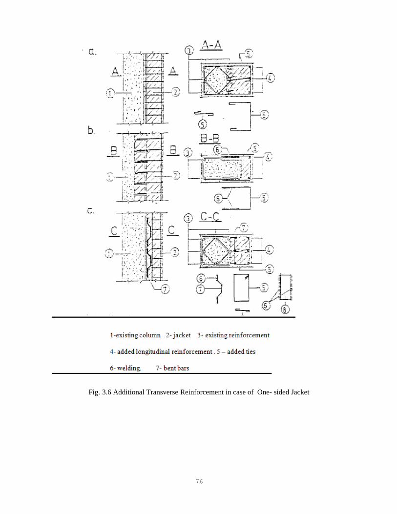
In the case of a one-sided jacket, adequate connection between existing and
new concrete is achieved by closely spaced, well anchored, additional transversal
reinforcement (Figure 3.6). The following solutions can be applied.
- Anchorage by ties to the existing vertical reinforcement (Figure 3.6(a)).
- Welding of additional ties to the column (Figure 3.6(b)).
- Connection by bent bars welded to the vertical reinforcement (Figure
3.6(c)).
Similar detailing is applied in case of two or three-sided jacketing.
In the usual four-sided jacketing, several solutions are possible (Figure 3.7):
- Jacketing with welded wire fabric and new concrete cover.
- Jacketing with connecting bent bars (Figure 3.7(a)).
- Jacketing with ties (Figure 3.7(b)).
75
Fig. 3.4 column jackets
Fig. 3.5 Passing New Vertical Reinforcement for Adequate Columns Strength
76
Fig. 3.6 Additional Transverse Reinforcement in case of One- sided Jacket

77
Fig. 3.7 Four – Sided Jacketing
78
3.2.3Reinforced Concrete Jacketing Conditions
- The strength of the new materials must be greater than those of the column.
- The thickness of the jacket should be at least 4 cm for shotcrete application or
10 cm for cast-in-situ concrete.
- The reinforcement should not be less than four bars for four-sided jacketing
and bar diameter should be at least 14 mm.
- Every corner and alternate longitudinal bar should have lateral ties with an
angle of bend of 135 degrees minimum. No intermediate bar should be father
than 10 cm from corner of the ties. In some cases, it will be necessary to drill
into the core of the column to place epoxy hooked ties into the hole or drill
completely through the existing column core to install new ties.
- The ties should be minimum 8 mm, and at least 1/3 of the vertical bar
diameter.
- Vertical spacing of ties is at most 20 cm. close to the joints the spacing should
not exceed 10 cm, within a length of 1/4 the clear height. In addition, the
spacing of ties should not exceed the thickness of the jacket.
Jackets can be made either with conventional or special cast-in-situ concrete or
by shotcrete (gunite). For both methods, the existing concrete must be thoroughly
roughened by chipping or heavy sandblasting and cleaned of all loose material, dust
and grease. The surface should be thoroughly moistened before placing the concrete
or shotcrete.

79
3.3: Strengthening of Reinforced Concrete Beams:-
The strengthening of beams is to provide strength and stiffness of beams to
resist gravity and seismic loads the chosen procedure must provide strength and
stiffness to the beams in relation to the columns. So that to avoid creating structures
of the "strong girder – weak column type", which tend to force seismic hinging and
distress into the column.
Depending on the type of damage (cracking crushing of concrete, rupture of
reinforcement or ties). The techniques for repairing and strengthening beams are
quite similar to those for columns.
3.3.1 Local Repairs
Injection is applied for repair of damaged beams with slight cracks only.
Epoxy or cement grout injections are made.
Removal and replacement should be applied when heavy damage like crushing
of concrete, deterioration of bond or rupture of reinforcement occurs. Before the
removal of crushed concrete or rupture reinforcement, the damaged beam must be
temporally supported. The replacement procedure for beams is similar to that of
columns. More attention must be paid to compact the new concrete under existing
beams or slabs, which is extremely difficult if placement access is not provided from
the top surface of the beam.
3.3.2Reinforced Concrete Jacketing of Beams
Reinforced concrete jacketing is done by adding concrete on one. Three or four
sides of a beam. To create bond between old and new concrete and for welding of the
added reinforcement to the existing, the concrete cover must be chipped away. An

80
irregular shaped concrete surface. Combined with anchoring welded stirrups. Provide
good shear and tensile connection of the jacket to the beam.
Reliable anchorage of vertical bars in joint areas by sufficient length or by
welding to anchors, is of great importance shear and ductility improvement can be
provided by stirrups on all sides of the beam. The legs of the stirrup should penetrate
and anchored into the slab at the top of the jacket.
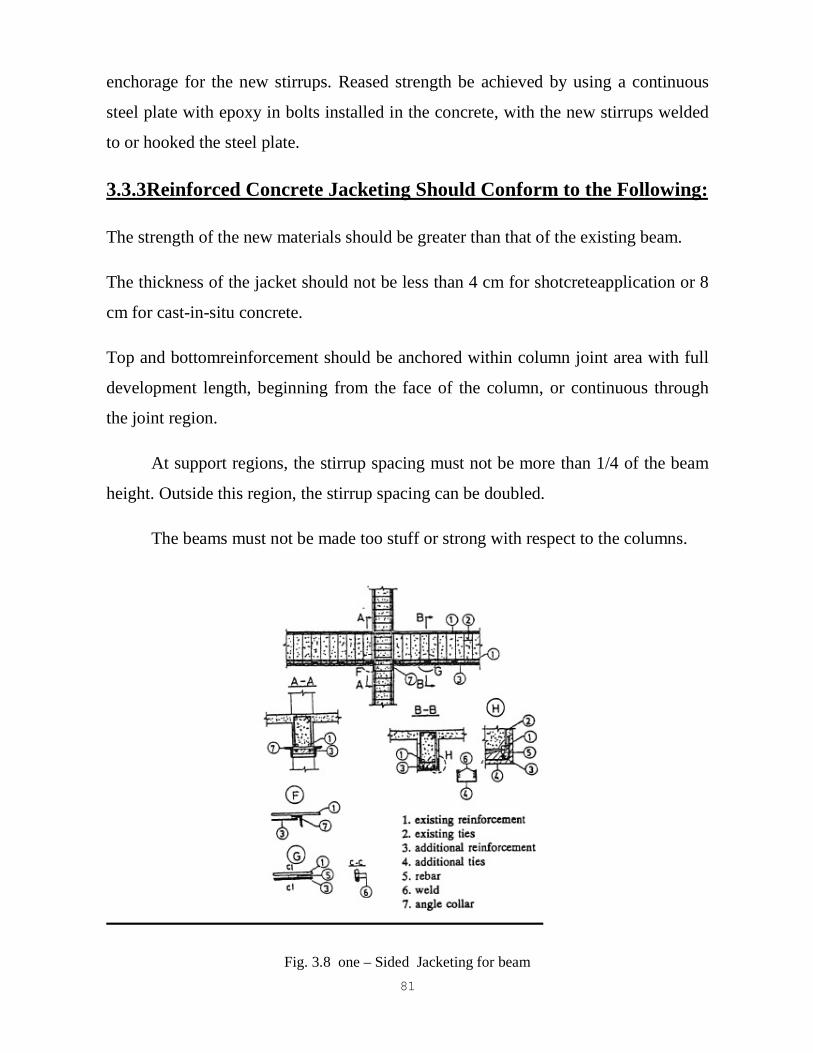
One-sided jackets (Figure 3.8) adding strength only to the beam soffit, should
be used only when it is necessary to increase the flexural strength of a beam. The
connection between existing and new longitudinal reinforcement is achieved by
connection bars (See Figure 3.8). The concrete cover should be away up to the
reinforcement and higher at existing stirrups. Additional welded to the existing ones
provide the connection between the existing and the newly-added concrete. The
longitudinal reinforcement bars should anchored in the support region, by welding
the reinforcement to a collar of angle profile, at the top of the column.
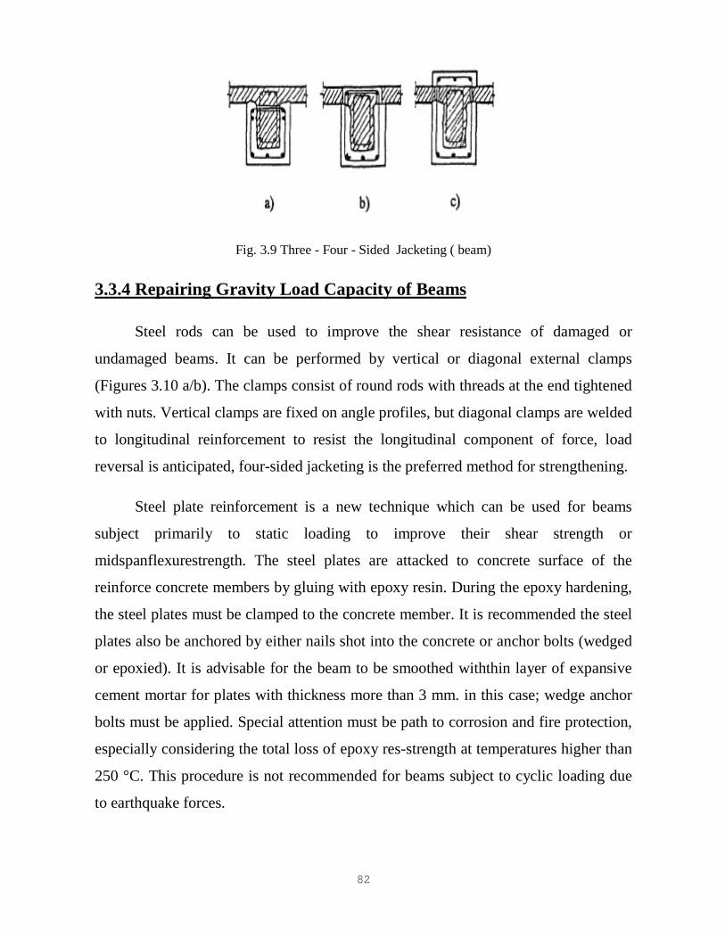
Sided jacketing (Figure 3.9) or beam encasement adds flexural and shear
because of the increase of reinforcement area and concrete cross section. Additional
longitudinal reinforcement should be connected with the existing reinforcement by
diagonally welded bent bars or small steel plates. The stirrups through holes drdled in
the slab and surround the whole beam. These holes also be used to place the concrete
in the part of the jacket beneath the slab. Litional reinforcement for negative bending
moments must be added over the surface into the beam region and outside of the
existing column. Specialntion must be paid to the anchorage of the longitudinal bars
in the joint on of the column jacket.
Heting three sides of the beam can also be installed beneath the soffit of the
(figure 3.10) Shotcrete is the most feasible method of installing this type jacket. Its
weakness is the anchorage of the new stirrups at the top of the. This detail is inferior
to that shown in Figure 3.11 as the effectiveness he detail depends on the dynamic
strength of the power driven nails and the finess of the strand to provide effective
81
enchorage for the new stirrups. Reased strength be achieved by using a continuous
steel plate with epoxy in bolts installed in the concrete, with the new stirrups welded
to or hooked the steel plate.
3.3.3Reinforced Concrete Jacketing Should Conform to the Following:
The strength of the new materials should be greater than that of the existing beam.
The thickness of the jacket should not be less than 4 cm for shotcreteapplication or 8
cm for cast-in-situ concrete.
Top and bottomreinforcement should be anchored within column joint area with full
development length, beginning from the face of the column, or continuous through
the joint region.
At support regions, the stirrup spacing must not be more than 1/4 of the beam
height. Outside this region, the stirrup spacing can be doubled.
The beams must not be made too stuff or strong with respect to the columns.
Fig. 3.8 one – Sided Jacketing for beam
82
Fig. 3.9 Three - Four - Sided Jacketing ( beam)
3.3.4 Repairing Gravity Load Capacity of Beams
Steel rods can be used to improve the shear resistance of damaged or
undamaged beams. It can be performed by vertical or diagonal external clamps
(Figures 3.10 a/b). The clamps consist of round rods with threads at the end tightened
with nuts. Vertical clamps are fixed on angle profiles, but diagonal clamps are welded
to longitudinal reinforcement to resist the longitudinal component of force, load
reversal is anticipated, four-sided jacketing is the preferred method for strengthening.
Steel plate reinforcement is a new technique which can be used for beams
subject primarily to static loading to improve their shear strength or
midspanflexurestrength. The steel plates are attacked to concrete surface of the
reinforce concrete members by gluing with epoxy resin. During the epoxy hardening,
the steel plates must be clamped to the concrete member. It is recommended the steel
plates also be anchored by either nails shot into the concrete or anchor bolts (wedged
or epoxied). It is advisable for the beam to be smoothed withthin layer of expansive
cement mortar for plates with thickness more than 3 mm. in this case; wedge anchor
bolts must be applied. Special attention must be path to corrosion and fire protection,
especially considering the total loss of epoxy res-strength at temperatures higher than
250 °C. This procedure is not recommended for beams subject to cyclic loading due
to earthquake forces.
83
3.4. Strengthening of Reinforced Concrete Shear Walls
The walls, becauseof their great stiffness and lateral strength, provide the most
earthquake resistance of the building. Therefore, a severely damaged or a poorlyigned
shear wall must be repaired or strengthened in order that the structure's ngth for
seismic force can be improved.
3.4.1Concrete Wall Repairs
Ection with epoxy resin for crack repairs in shear has become a standard ctice
over the last decade. If neither bond deterioration nor concrete crushing the occurred,
epoxy injections are capable of restoring approximately the original wall strength.
However, the repaired wall will never achieve the stiffness of the ginal wall. Not all
of the small cracks can be epoxy injected. Another advantage is the rapid loss of
strength of epoxy under fire. Epoxy repair of walls is simple, fast and economical,
without changing the original wall size and hout evacuation of the inhabitants. Higher
strength in walls than the original ength cannot be attained by epoxy injections.
Therefore, if additional strength required, another technique must be used.
Removal and replacement should be applied for large cracks, partially crushed
concrete and buckled reinforcement. After removing the loose concrete and
toughening and cleaning the remaining surface, additional reinforcement or molded
wire fabric should be placed. The choice of repair material (polymer mortar, cement
mortar, concrete or shotcrete) depends on the degree of damage, the desired repair
characteristics and the site conditions. Non-shrinkage or expansive cement for mortar
and concrete is often desirable. Special care must repaid to adequately compact the
new concrete, especially at contact regions with the existing concrete.
84
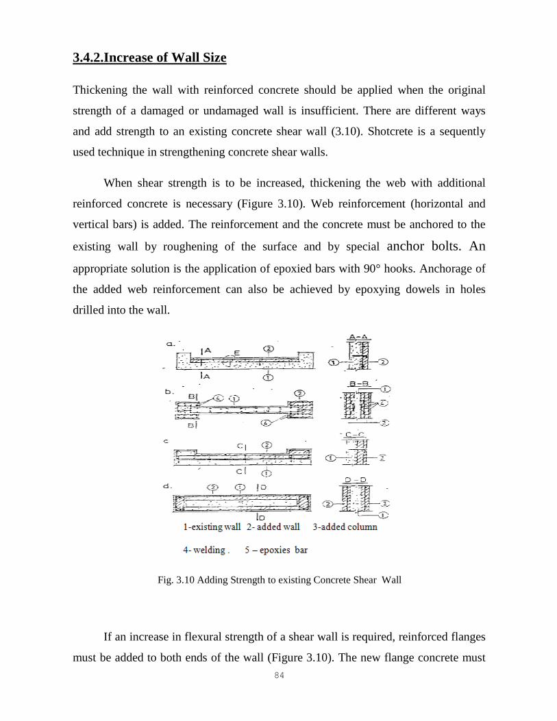
3.4.2.Increase of Wall Size
Thickening the wall with reinforced concrete should be applied when the original
strength of a damaged or undamaged wall is insufficient. There are different ways
and add strength to an existing concrete shear wall (3.10). Shotcrete is a sequently
used technique in strengthening concrete shear walls.
When shear strength is to be increased, thickening the web with additional
reinforced concrete is necessary (Figure 3.10). Web reinforcement (horizontal and
vertical bars) is added. The reinforcement and the concrete must be anchored to the
existing wall by roughening of the surface and by special anchor bolts. An
appropriate solution is the application of epoxied bars with 90° hooks. Anchorage of
the added web reinforcement can also be achieved by epoxying dowels in holes
drilled into the wall.
Fig. 3.10 Adding Strength to existing Concrete Shear Wall
If an increase in flexural strength of a shear wall is required, reinforced flanges
must be added to both ends of the wall (Figure 3.10). The new flange concrete must
85
be confined by appropriately detailed, closely spaced hoops and cross ties. The
anchorage of the flange concrete to the original wall is very important. It can be
performed by welding of special bent bar connectors to the new and the old
reinforcement or by epoxied anchor bars.
Shear forces between the shear wall and the floor slab must be transmitted. For
this purpose, concrete dowel connections are made by opening holes through the slab.
These holes also serve to concrete the new wall parts beneath the slab. Diagonal
reinforcement bars passing through the slab and anchored in the upper story and
lower story walls, provide an additional connection for shear transfer.
To provide bond between the old and the new concrete and for welding connection
bars to the reinforcement, some concrete cover must be chipped away the original
wall surface should be roughened, any paint or plaster removed additional shear is
transmitted from the existing to the new wall by epoxied dowels in the existing
surface.
Reinforced concrete thickening of shear walls should slao conform to the
following provisions:
- The strength of the new materials should be greater than those of the existing
walls.
- The web thickness of the new material should be at least 5 cm. the thickness of
the new shear wall flanges should be at least 10 cm.
- Both the horizontal web reinforcement and the vertical web reinforcement
must not be less than 0.0025 times the gross area of the wall thickening.
- The area of the vertical reinforcement concentrated at the wall ends must not
be less than 0.0025 times the gross area of the newly added cross section.
86
- The end wall ties should not be less than 8 mm in diameter. The tie spacing
should be no more than the thickness of the wall end thickening or miximum
15 cm.
- The new concrete should be anchored to the existing concrete with epoxied
hooked dowels at a maximum of 60 cm in each direction and the existing wall
surface should be thoroughly roughened.
3.5. Strengthening of Slabs
Slabs have to carry vertical gravity loads. However, they must also provide
shragm action and be compatible with all lateral resistant elements of the cture.
Therefore, slabs must possess strength and stiffness. Damages in slabs crally occur
in locations with irregularities such as near large openings, at centration of
earthquake forces in slabs close to widely spaced shear walls and staircase landings.
Repair of slabs is necessary when damage occurs. Mgthening is applied when there is
insufficient slab strength or for increased mgth in the region of newly-introduced
shear walls.
3.5.1Repairs
Action should be applied for repair of cracks. Epoxy or cement grout can be
add. Restoration of connection between the separated concrete parts can be ieved.
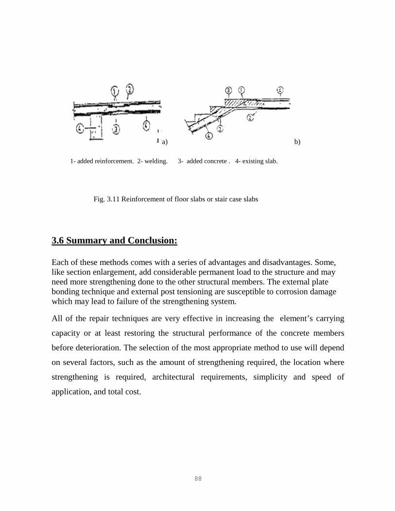
Removal and replacement procedures should be applied in cases of
spalledconcrete and broken or buckled reinforcement. Floor slabs or staircase slabs
can be repaired in this manner (Figure 3.11). After the removal of removal of the
unsound reterials new reinforcement is incorporated and it is welded to the existing
reinforcement. Concrete with better properties than the existing concrete should be
used.
87
3.5.2.Increasing Slab Thickness:
Strengthening by thickening of slabs should be applied in cases of insufficient length
or stiffness. The thickening can be done above or under the existing slab. The first
case the flexural strength is increased because of the increased effective depth and
ability to add negative reinforcement as reports. In the second case the flexural
strength increases cause of the newly added tension reinforcement. In the case of
normal concrete is used; in the case of the application of shotcrete is more suitable.
The strengthening according to case provides greater floor slab stiffness for anhragm
action and is strongly recommended. In case the performance will improved if the
beams are also jacketed.
Or compatibility of the slab and the newly-added reinforce concrete, excellent wear
bond is of great importance. It can be achieved by the following:
Reinforced concrete lugs
Rough surface, realized by gluing of sand grains with epoxy resin
- Epoxied steel dowel bars
- Additionally shaped concrete lugs in slab voids
- Steel dowels made either by steel angle, anchored by power concrete nails or
by epoxied bolts or wedge anchor bolts
Roughening of the surface improve the bond between original and added concrete. It
can be performed by sandblasting or by chipping with special mechanical equipment.
88
a) b)
1- added reinforcement. 2- welding. 3- added concrete . 4- existing slab.
Fig. 3.11 Reinforcement of floor slabs or stair case slabs
3.6 Summary and Conclusion:
Each of these methods comes with a series of advantages and disadvantages. Some,
like section enlargement, add considerable permanent load to the structure and may
need more strengthening done to the other structural members. The external plate
bonding technique and external post tensioning are susceptible to corrosion damage
which may lead to failure of the strengthening system.
All of the repair techniques are very effective in increasing the element’s carrying
capacity or at least restoring the structural performance of the concrete members
before deterioration. The selection of the most appropriate method to use will depend
on several factors, such as the amount of strengthening required, the location where
strengthening is required, architectural requirements, simplicity and speed of
application, and total cost.

89
89
4CHAPTER
Strengthening of Reinforced Concrete Structure Elements
Using Steel Plates
Strengthening Design of Reinforced Concrete Beams by Addition .1 4
of Steel Plates
4.1.1 Objective
This Chapter presents a synthesis of the strengthening design of reinforced
concrete beams and columns by external reinforcement. The design criteria, the
methods of analysis and the evaluation of the design resistant bending moment and
shear are presented. Construction details for this type of strengthening are also
presented.
4.1.2Keywords
Strengthening, reinforced concrete beams, design, bending, shear.
4.1.3 Introduction
The need to strength a structure is caused byproblems due to a wrong design,
the degradation of the characteristics of thematerials along the time and the
amplification of the load capacity caused by a new utilization of the building. Other
causeis the publication of new design codes that increases the actions,such as the
seismic action.
The design methods and criteria for thebending and shear strengthening of
reinforced concrete beams byexternal reinforcement addition are presented in this
paper.
90
The structure strengthening design must be precededby a strength assessment of the
existent structure. This involvesa compilation of all the information related to the
build erection and design, a structural inspection and a load capacity evaluation.
Taking into account the objectives ofthe strengthening there are various types of
interventions that can be adopted: demolition of all the structure, substitution of some
structural elements, new structural elements introduction or the strengthening of the
elements introduction or the strengthening of the existent elements.
The conception must be based on the structural assessment and the objectives
to achieve. That conception must be established in the building, by economic reasons,
and to reduce the consequences that the strengthening work causes in the non –
structural elements and in the normal use of the building.
4.1.4 Strengthening design criteria
The strengthening design includes the Ultimate Limit States and the Limit
States verifications. In the analytical evaluation of the structural resistant capacity
there are used models that simulates the actions, the materials characteristics, the
structure behavior, the design criteria and the safety level. In the strengthening design
the serviceability Limit States verification, the existent damages and the lower
stiffness of the strengthened elements must be considered. A reduction of the cross
sections area and inertia is usually adopted.

91
In strengthening design the Ultimate Limit States verification is expressed by:
Where S denotes the F loads effects, YF the actions partial safety factor, R the
cross sections strength, fK the materials characteristic strength and Ym the partials
materials safety factor. The subscript d means a design value and the superscript'
refers a value that can be different from that one usually adopted in the design of a
new structure. This is caused by the additional uncertainties related to the existent
damage simulation and, s a consequence of the structure assessment, by the
possibility to reduce the materials strength uncertainly.
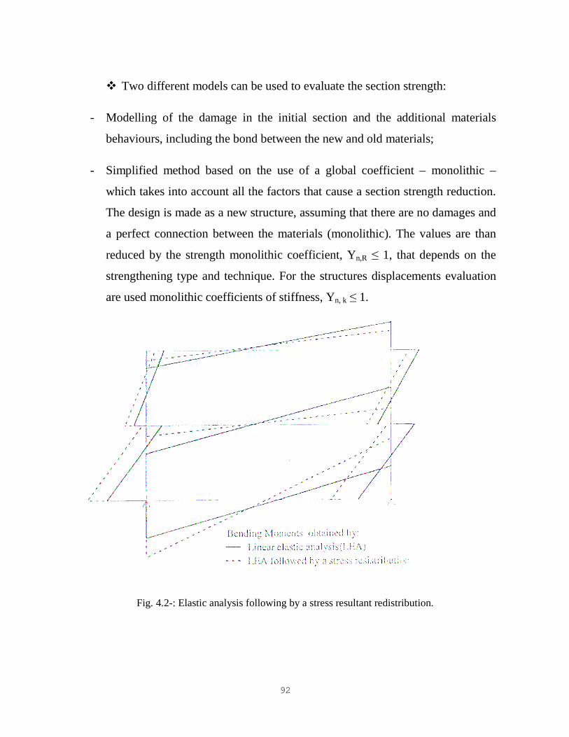
The load effects evaluation in the strengthening design process is generally
based on plastic models, figure 4.1, or elastic analysis followed by stresses resultant
redistribution, as shown in figure 4.2, because the need to reduce the number of
strengthened elements and the necessity to use the full strength capacity of the
existing elements, the elastic model is not usually adequate.
Fig. 4.1- Plastic analysis – Ultimate load of a beam, pu.
92
� Two different models can be used to evaluate the section strength:
- Modelling of the damage in the initial section and the additional materials
behaviours, including the bond between the new and old materials;
- Simplified method based on the use of a global coefficient – monolithic –
which takes into account all the factors that cause a section strength reduction.
The design is made as a new structure, assuming that there are no damages and
a perfect connection between the materials (monolithic). The values are than
reduced by the strength monolithic coefficient, Yn,R ≤ 1, that depends on the
strengthening type and technique. For the structures displacements evaluation
are used monolithic coefficients of stiffness, Yn, k ≤ 1.
Fig. 4.2-: Elastic analysis following by a stress resultant redistribution.

93
4.1.5 Description of The Strengthening Technique
For the elements with insufficient reinforcements and a good concrete quality,
the external reinforcements addition is the more adequate technique. There are
usually used steel plates or hot rolled sections, mainly angle profiles as
reinforcements. To mobilise the additional steel strength with low deformations of
the strengthened element it is convenient the use of a low tensile strength steel, such
as the Fe 360.
In terms of serviceability Limit states this type of strengthening increase the
section inertia and stiffness and as a consequence of the resin injection that re-
established the continuity of the element.
The additional steel reinforcements are connecting to the initial section by
gluing with injected epoxy resin. The use of high strength steel bolts (steel anchor)
particularly in the anchorage zones, near the ends of the plates is convenient. The
strengthening efficiency is mainly depending on the connection behavior.
When the connection is only guaranteed by the resin a steel plate with a
maximum 5 mm thick and 200 mm width is recommended. The resin thick must be
comprehended between 1 and 3 mm. a higher resin thick leads to a lower bond
capacity. Figure 3 and 4 shows the recommended steel plates dimension, j. Appleton
and A. Gomes (1997)>
To allow the additional steel mobilization for the service loads must be
removed from the structures during the strengthening execution.
A careful preparation of the concrete and steel surfaces is necessary to achieve
a good bond quality. The concrete surface preparation is done by alight pneumntic
needle hammer in order to increase the rough ness. A high roughness is inconvenient
because it lead to an elevate resin thick. The steel plates are shotblastedand protected

94
against the corrosion with a plastic film for transport and handling.the plastic film is
removed before the steel plate application.
Fig. 4.3-: Flexural strengthening – recommended dimensions limits.
Fig. 4.4-: Shear strengthening – recommended dimensions limits.
After surface preparation, the reinforcing steel plates are installed free of
adhesive, using the bolts placed into holes drilled in the concrete member. To allow
for complete confinement of the airdrop, plate boundaries and both heads are sealed
with an epoxy mortar. Small diameter tubes are left around the plate boundaries. The
injection of the resin is made through those tubes. In the final of the injection, the
tubes are blocked to allow some pressure in the resin. This causes the penetration of
the resin in the small cavities and cracks.
95
The more relevant resin properties for this type of application are the viscosity,
the pot life, the hardeningtime, the elasticity modulus and the strength. It is not
convenient the application of the resin with a ambient temperature lower than 10 °C,
J. Appleton and V. Silva (1992).
The strengthening of a concrete beams by addition of steel plates involves the
followings steps:
- Concrete surface preparation;
- Positioning of the steel plates fixed with metallic anchors;
- Sealing of the steel plates boundaries with an epoxy mortar;
- Epoxy resin injection.
4.1.6 Beams strengthening Design:
4.1.6.1Bending
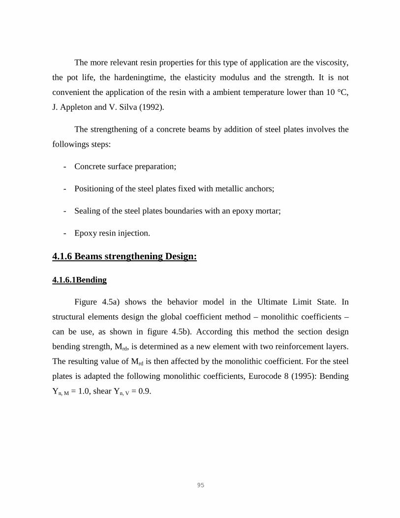
Figure 4.5a) shows the behavior model in the Ultimate Limit State. In
structural elements design the global coefficient method – monolithic coefficients –
can be use, as shown in figure 4.5b). According this method the section design
bending strength, Mrd, is determined as a new element with two reinforcement layers.
The resulting value of Mrd is then affected by the monolithic coefficient. For the steel
plates is adapted the following monolithic coefficients, Eurocode 8 (1995): Bending
Yn, M = 1.0, shear Yn, V = 0.9.
96
Fig. 4.5-: Bending strength models.
If the distance between the two reinforcement layers is small, the Mrdvalue can
be determined by a equivalent reinforcement area, Aseq
, with a tensile strength fisyd,
positioned at the mechanical center. The design bending strength can be expressed
by:
Assuming z ≈ 0.9 d gives:
Usual design tables for reinforced concrete section can be used with the
previous equation. The strengthening steel area is given by:
97
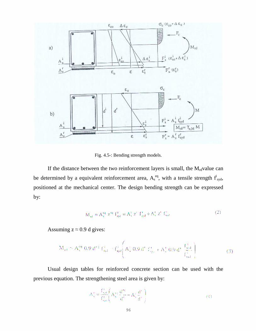
The connection between the steel plate and the concrete strength is determined
assuming a plastic distribution of bond stresses as shown in figure 4.6.
The design connection strength verification can be expressed by following
equations:
- Connection without bolts.
- Connection with bolts.
Fig. 4.6-: Distribution of bond stresses in the steel plate connection to the concrete.
Fb denotes the bolt design shear strength, n the number of bolts positioned in
the length L/2, b the plate width and trd the design bond strength of the
steel/resin/concrete connection. Is recommended a value of 0.5 MPA for trd when
metallic anchors are used, J. Appleton and A. Gomes (1997).
98
In the connection serviceability verification, it is recommended an elastic
model to the shear stresses evaluation. For the service load level, the connection
behavior depends mainly on the resin. Experimental tests have shown when the
metallic anchors were not applied early collapses occurs caused by the steel plates
debond, J. Alfaiate (1986). The presence of the bolts in the plate extremities led to
ahigher ultimate load capacity mobilizing the full strength of the steel plate. Other
advantage in the use of the bolts is the fire strength.
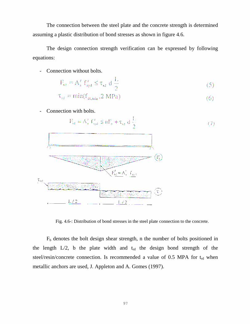
To improve the connection strength, the steel plates must be extended until the
edges of the beam and anchored to the column as shown in figure 4.7a). in a
continuous beam the forces can be transferred along the columns by the connection of
the steel plates to a collar usually made by angles as shown in figure 4.7b). this collar
is also useful in column strengthening.
Fig. 4.7-: Connection details of the steel plates: a) Beam edges; b) Beam column connection.
4.1.6.2.Shear
99
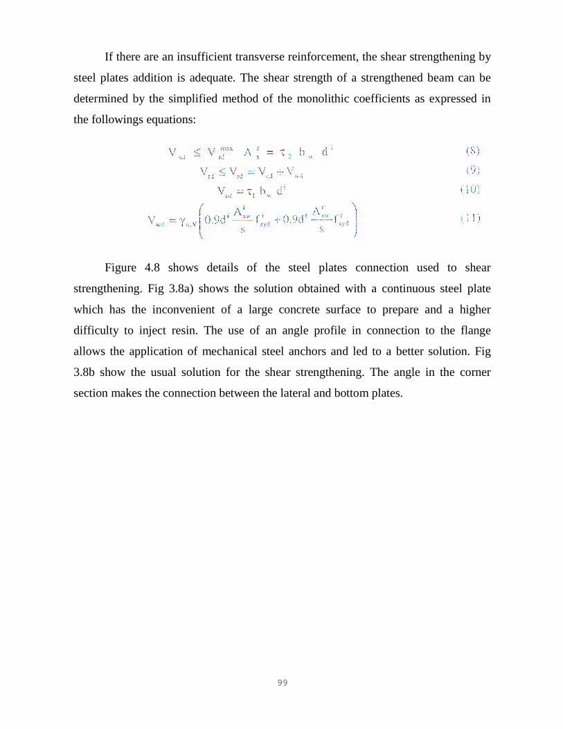
If there are an insufficient transverse reinforcement, the shear strengthening by
steel plates addition is adequate. The shear strength of a strengthened beam can be
determined by the simplified method of the monolithic coefficients as expressed in
the followings equations:
Figure 4.8 shows details of the steel plates connection used to shear
strengthening. Fig 3.8a) shows the solution obtained with a continuous steel plate
which has the inconvenient of a large concrete surface to prepare and a higher
difficulty to inject resin. The use of an angle profile in connection to the flange
allows the application of mechanical steel anchors and led to a better solution. Fig
3.8b show the usual solution for the shear strengthening. The angle in the corner
section makes the connection between the lateral and bottom plates.

100
Fig. 4.8-: Shear strengthening details.
4.2. Strengthening Design of Reinforced Concrete Columns by
Addition steel Plates
The columns strengthening scopes are the increase of the confinement, flexural
strength and axial strength. The confinement level increase led to an improvement in
the ductility and seismic behavior of the structure and to an axial capacity load
increase.
The more adequate strengthening technique to the axial force capacity is the
jacketing. The external addition of steel is more suitable in cases that have
reinforcement insufficiency. Steel plates or profiles (angles) are usually applied.
101
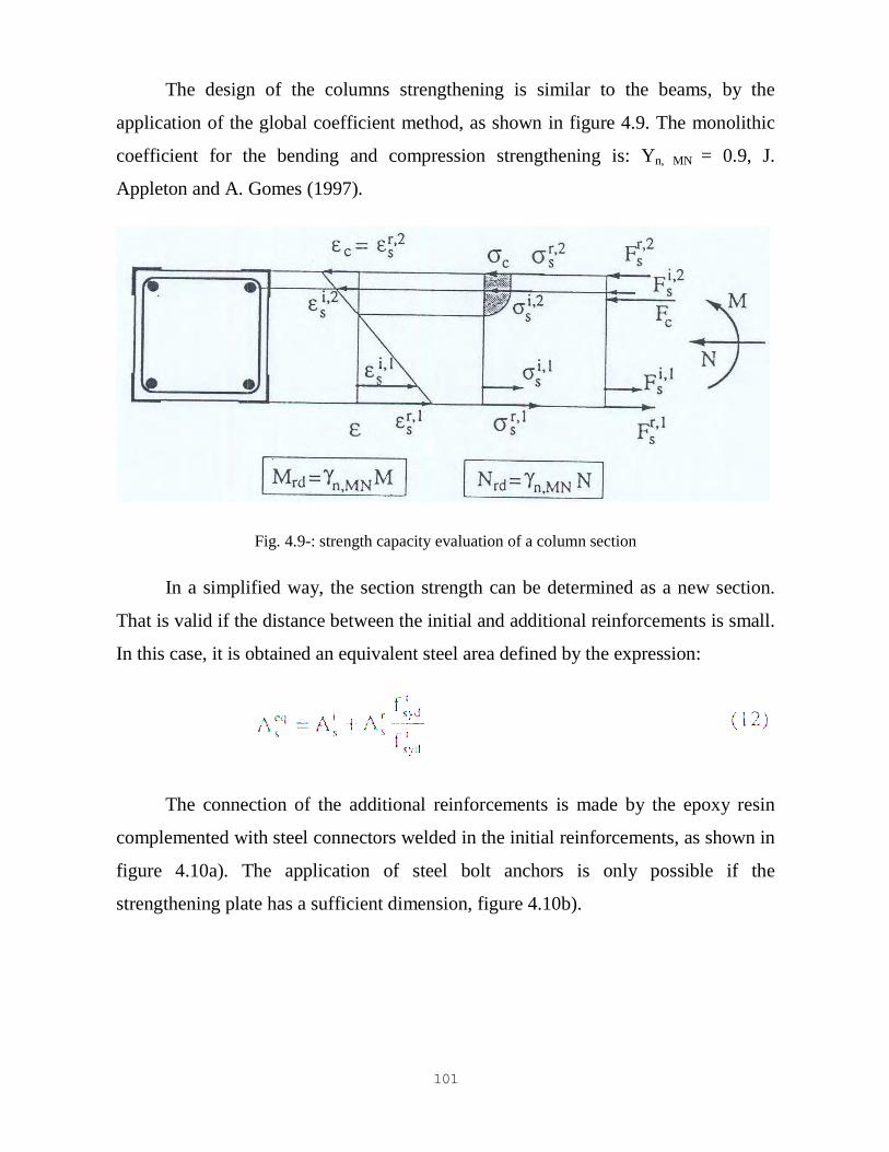
The design of the columns strengthening is similar to the beams, by the
application of the global coefficient method, as shown in figure 4.9. The monolithic
coefficient for the bending and compression strengthening is: Yn, MN = 0.9, J.
Appleton and A. Gomes (1997).
Fig. 4.9-: strength capacity evaluation of a column section
In a simplified way, the section strength can be determined as a new section.
That is valid if the distance between the initial and additional reinforcements is small.
In this case, it is obtained an equivalent steel area defined by the expression:
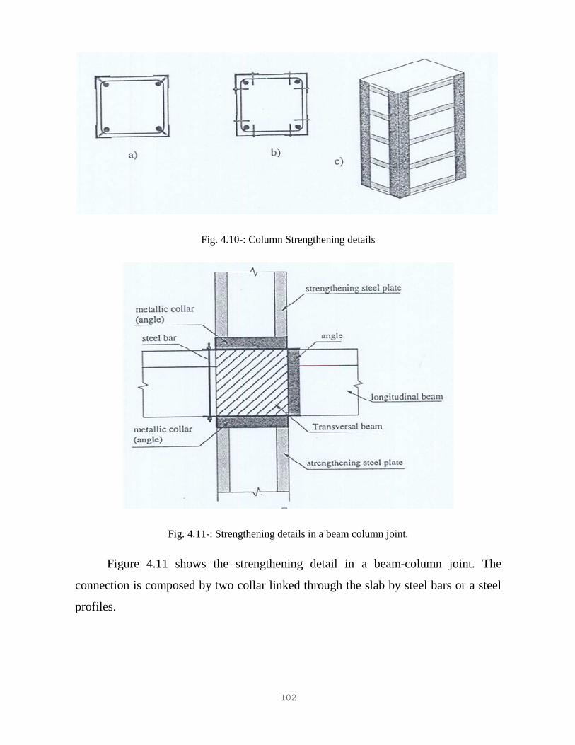
The connection of the additional reinforcements is made by the epoxy resin
complemented with steel connectors welded in the initial reinforcements, as shown in
figure 4.10a). The application of steel bolt anchors is only possible if the
strengthening plate has a sufficient dimension, figure 4.10b).
102
Fig. 4.10-: Column Strengthening details
Fig. 4.11-: Strengthening details in a beam column joint.
Figure 4.11 shows the strengthening detail in a beam-column joint. The
connection is composed by two collar linked through the slab by steel bars or a steel
profiles.

103
Figure 4.12 shows the strengthening steel plates connection to the foundation.
It is used a colar made by a steel angle profile which is connected by a steel anchor.
Fig. 4.12: Steel plate connection in the foundation.
111
Chapter 5
Strengthening of Reinforced Concrete Structure Elements
Using F.R.P Materials
5.1.Introduction
For eight years New Zealand has been to the forefront in the development
and use of FRP materials as a means of strengthening civil engineering
structures. However, as of this day, there is no national guideline available
which sets down recommendations for the design and detailing of FRP for
strengthening of civil engineering structures. The authors have spent 3 years
researching the technology and the available guidelines worldwide. This paper
sets out proposals for interpretation of these guidlelines so that they may be
used in the detailing of typical NZ structures.
5.1.1. Generic Information
The use of fibre reinforced polymers (FRP) as reinforcement for structures is rapidly
gaining appeal. This is due to the many advantages these materials afford when
compared to conventional steel reinforcement or concrete encasements. Their light
weight, high strength-to-weight ratio, ease of handling and appplication, lack of
requirement for heavy lifting and handling equipment and corrosion resistance are
some factors that are advantageous in repair, retrofitting and rehabilitiation of civil
engineering structures. While no country yet has a national design code, several national guidelines [1-6] offer
the state-of- the-art in selection of FRP systems and the design and detailing of
structures incorporating FRP reinforcement. However, there exists a divergence of opinion about certain aspects of the detailing
between
guidelines. This is to be expected as the use of the relatively new material develops
worldwide. Much research is being carried out at institutions around the world and it
is expected that design criteria will continue to be enhanced as the results of this
research become know in the coming years. This development process is akin to
that which occurred in the 60s and 70s in the field of prestressed concrete. The main areas of detailing where this divergence occurs are presented for discussion
in this paper. Recommendations are given as to which guideline should be followed.
However, as in all design and detailing carried out by responsible engineers, the final
decision as to what criteria is chosen must rest with the designer.
112
5.1.2.Types and Properties Of FRP Used For Strengthening
The main fibre types used are carbon (CFRP), glass (GFRP) and aramid (AFRP).
GFRP comes in two types – E-glass and AR glass. E-glass is the most common
form used but it has the disadvantage that it is attacked by the alkali in fresh
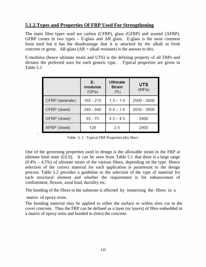
concrete or grout. AR-glass (AR = alkali resistant) is the answer to this. E-modulus (hence ultimate strain and UTS) is the defining property of all FRPs and
dictates the preferred uses for each generic type. Typical properties are given in
Table 5.1
. Table 5. 1: Typical FRP Properties (dry fiber)
One of the governing properties used in design is the allowable strain in the FRP at
ultimate limit state (ULS). It can be seen from Table 5.1 that there is a large range
(0.4% – 4.5%) of ultimate strain of the various fibres, depending on the type. Hence
selection of the correct material for each application is paramount to the design
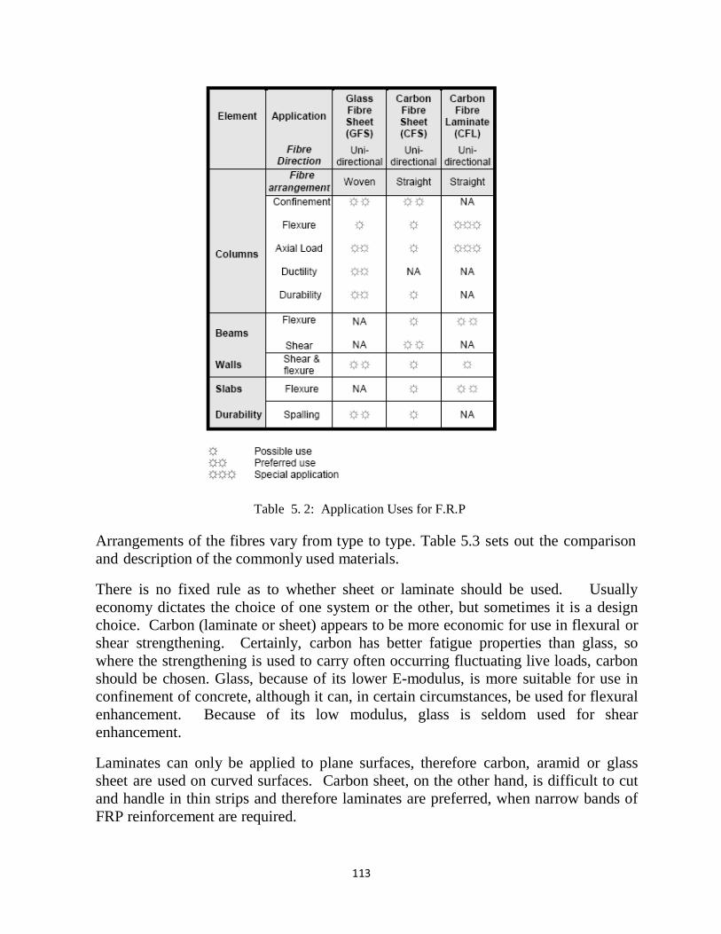
process. Table 5.2 provides a guideline to the selection of the type of material for
each structural element and whether the requirement is for enhancement of
confinement, flexure, axial load, ductility etc. The bonding of the fibres to the substrate is affected by immersing the fibres in a matrix of epoxy resin.
The bonding material may be applied to either the surface or within slots cut in the
cover concrete. Thus the FRP can be defined as a layer (or layers) of fibre embedded in
a matrix of epoxy resin and bonded to (into) the concrete.
113
Table 5. 2: Application Uses for F.R.P
Arrangements of the fibres vary from type to type. Table 5.3 sets out the comparison
and description of the commonly used materials. There is no fixed rule as to whether sheet or laminate should be used. Usually
economy dictates the choice of one system or the other, but sometimes it is a design
choice. Carbon (laminate or sheet) appears to be more economic for use in flexural or
shear strengthening. Certainly, carbon has better fatigue properties than glass, so
where the strengthening is used to carry often occurring fluctuating live loads, carbon
should be chosen. Glass, because of its lower E-modulus, is more suitable for use in
confinement of concrete, although it can, in certain circumstances, be used for flexural
enhancement. Because of its low modulus, glass is seldom used for shear
enhancement. Laminates can only be applied to plane surfaces, therefore carbon, aramid or glass
sheet are used on curved surfaces. Carbon sheet, on the other hand, is difficult to cut
and handle in thin strips and therefore laminates are preferred, when narrow bands of
FRP reinforcement are required.
114
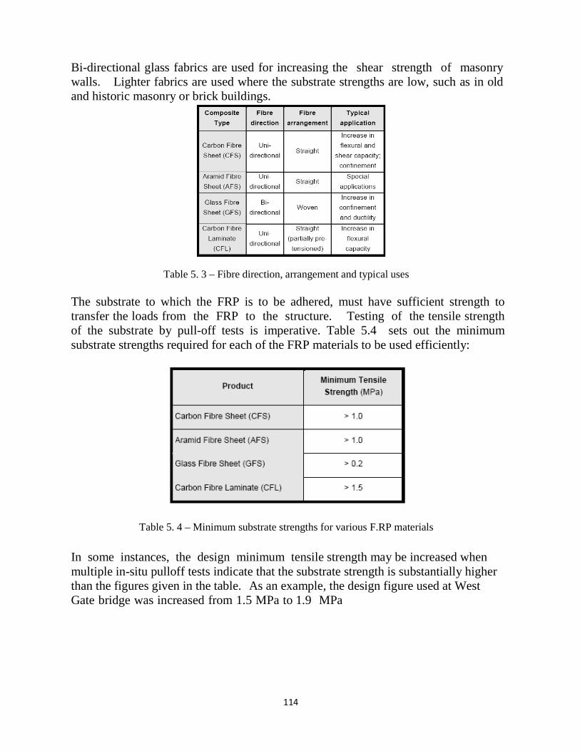
Bi-directional glass fabrics are used for increasing the shear strength of masonry
walls. Lighter fabrics are used where the substrate strengths are low, such as in old
and historic masonry or brick buildings.
Table 5. 3 – Fibre direction, arrangement and typical uses
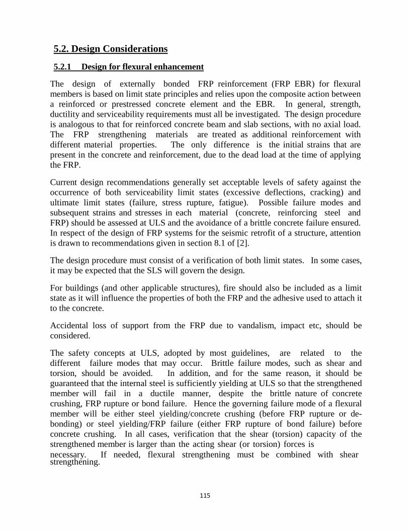
The substrate to which the FRP is to be adhered, must have sufficient strength to
transfer the loads from the FRP to the structure. Testing of the tensile strength
of the substrate by pull-off tests is imperative. Table 5.4 sets out the minimum
substrate strengths required for each of the FRP materials to be used efficiently:
Table 5. 4 – Minimum substrate strengths for various F.RP materials
In some instances, the design minimum tensile strength may be increased when
multiple in-situ pulloff tests indicate that the substrate strength is substantially higher
than the figures given in the table. As an example, the design figure used at West
Gate bridge was increased from 1.5 MPa to 1.9 MPa
115
5.2. Design Considerations
5.2.1 Design for flexural enhancement
The design of externally bonded FRP reinforcement (FRP EBR) for flexural
members is based on limit state principles and relies upon the composite action between
a reinforced or prestressed concrete element and the EBR. In general, strength,
ductility and serviceability requirements must all be investigated. The design procedure
is analogous to that for reinforced concrete beam and slab sections, with no axial load.
The FRP strengthening materials are treated as additional reinforcement with
different material properties. The only difference is the initial strains that are
present in the concrete and reinforcement, due to the dead load at the time of applying
the FRP. Current design recommendations generally set acceptable levels of safety against the
occurrence of both serviceability limit states (excessive deflections, cracking) and
ultimate limit states (failure, stress rupture, fatigue). Possible failure modes and
subsequent strains and stresses in each material (concrete, reinforcing steel and
FRP) should be assessed at ULS and the avoidance of a brittle concrete failure ensured.
In respect of the design of FRP systems for the seismic retrofit of a structure, attention
is drawn to recommendations given in section 8.1 of [2]. The design procedure must consist of a verification of both limit states. In some cases,
it may be expected that the SLS will govern the design. For buildings (and other applicable structures), fire should also be included as a limit
state as it will influence the properties of both the FRP and the adhesive used to attach it
to the concrete. Accidental loss of support from the FRP due to vandalism, impact etc, should be
considered. The safety concepts at ULS, adopted by most guidelines, are related to the
different failure modes that may occur. Brittle failure modes, such as shear and
torsion, should be avoided. In addition, and for the same reason, it should be
guaranteed that the internal steel is sufficiently yielding at ULS so that the strengthened
member will fail in a ductile manner, despite the brittle nature of concrete
crushing, FRP rupture or bond failure. Hence the governing failure mode of a flexural
member will be either steel yielding/concrete crushing (before FRP rupture or de-
bonding) or steel yielding/FRP failure (either FRP rupture of bond failure) before
concrete crushing. In all cases, verification that the shear (torsion) capacity of the
strengthened member is larger than the acting shear (or torsion) forces is
necessary. If needed, flexural strengthening must be combined with shear strengthening.
116
The design approach to strengthened sections is normally based upon a trial and error
approach, which can be easily carried out by means of a simple spreadsheet. The
initial type, size and length of the FRP reinforcements are selected at random. Then
the flexural safety of the strengthened section is checked by analysing its limit states.
If the safety check fails, or if the selected FRP strengthening elements are not
economical, a new size or type of element is selected and the process is run again.
Usually a few iterations are sufficient to arrive at a safe and economical solution. Custom designed software exists for the design of FRP strengthening using CFRP
laminates. One particularly good programme is available in the public domain on
www.frp.at. It is written for either the ACI code (US), the British, French and German
codes, as well as Eurocode 2. The properties of the FRP used in this programme are
those relating to the products manufactured by the owner of the software. The following assumptions are considered valid for the concept of design of FRP EBR: • There is a perfect bond between the FRP and the bonded substrate. This is, in
fact, achieved without difficulty in practice, and failure, if it occurs, is always in the
substrate.
• Plane section remain plane (Bernoulli’s principle).
• The stress-strain responses for concrete and steel reinforcement follow the
idealised curves presented in current codes and standards.
• FRP has a linear elastic response.
• The tensile strength of the concrete is ignored.
• Loads which are in place at the time of application of the FRP cause the
element being reinforced to act within its elastic limit.
• The existing conditions have been properly evaluated (this includes steel areas
and properties, concrete strength, existing moments and shear forces, steel and
concrete strains, etc).
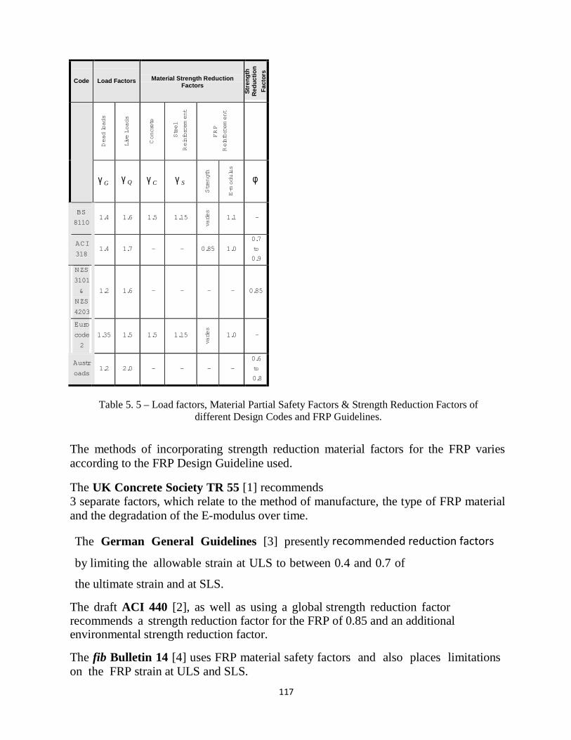
For the ultimate and serviceability limit states, the design loading is obtained by
multiplying the characteristic dead and imposed loads by appropriate load factors and
strength reduction factors. Designers must incorporate factors from design codes
acceptable to the location of the works. Figure 5 sets out load factors, partial
factors of safety and material reduction factors for some codes. In addition, it is
normal to use strength reduction factors when calculating ultimate strength. Some
codes (EC2 and BS 8110, for example) use separate material strength reduction factors
for reinforcing steel and concrete, while others (ACI 318, NZS 3101 and Austroads
Bridge Design Code, for example) use global strength reduction factors for these two
materials.
117
Code
Load Factors
Material Strength Reduction
Factors
Str
en
gth
R
ed
uc
tio
n
Fa
cto
rs
Dead
lo
ad
s
Liv
e L
oa
ds
Co
ncre
te
Ste
el
Rein
forc
em
ent
F
RP
Rein
forc
em
en
t
γ G
γ Q
γ C
γ S
Str
en
gth
E-m
odu
lus
φ
BS
8110
1.4
1.6
1.5
1.15
vari
es
1.1
-
ACI
318
1.4
1.7
-
-
0.85
1.0
0.7
to
0.9
NZS
3101
&
NZS
4203
1.2
1.6
-
-
-
-
0.85
Euro
code
2
1.35
1.5
1.5
1.15
vari
es
1.0
-
Austr
oads
1.2
2.0
-
-
-
-
0.6
to
0.8
Table 5. 5 – Load factors, Material Partial Safety Factors & Strength Reduction Factors of
different Design Codes and FRP Guidelines.
The methods of incorporating strength reduction material factors for the FRP varies
according to the FRP Design Guideline used. The UK Concrete Society TR 55 [1] recommends
3 separate factors, which relate to the method of manufacture, the type of FRP material
and the degradation of the E-modulus over time. The German General Guidelines [3] presently recommended reduction factors
by limiting the allowable strain at ULS to between 0.4 and 0.7 of the ultimate strain and at SLS.
The draft ACI 440 [2], as well as using a global strength reduction factor recommends a strength reduction factor for the FRP of 0.85 and an additional environmental strength reduction factor.
The fib Bulletin 14 [4] uses FRP material safety factors and also places limitations
on the FRP strain at ULS and SLS.
118
Presently there are no Codes of Practice that include for the use of FRP as a
reinforcement material. The designer therefore must take into account suitable
limitations on the use of FRP, either by separate material reduction factors as per the
UK and fib Guidelines, additional strength reduction factors used in conjunction
with the global reduction factor, as for ACI 440, or a fixed upper limit of allowable
strain, as per the German General Guideline and ACI 440. All guidelines limit the stress/strain in the FRP to avoid de-bonding, which can occur
in several mechanisms. In addition, due to the general decrease in ductility of a
member strengthened with FRP, care must be taken to ensure ductility is preserved, by
ensuring the internal steel will sufficiently yield at failure. This is done by limiting the
depth of the compression zone at ULS.
5.2.2 Design values for material properties
As mentioned above, at the time of writing there are no Codes of Practice that set
down the requirements for the design and execution of concrete strengthening using
FRP. However, there are at least eight national guidelines that have been
produced by recognised authorities and these can be accepted as state-of-the-art
guidelines for the present. Nevertheless it must be recognised that the use of FRP as a
strengthening medium, is a relatively new art and that research is being undertaken in
many centres worldwide. The results of this research will undoubtedly cause the
recommendations to be varied as experience is gained. The various FRP Design Recommendations treat the strength reduction of the FRP
material in different ways.
UK Concrete Society TR No. 55 [1]
TR 55 [1] postulates that the partial safety factors to be applied to the characteristic
mechanical properties are a function of the type of fibre and the manufacturing/site
application process. Thus
Where � mf depends on the type of fiber and �mm
depends on the manufacturing and/or site
application process. Typical values are given in ( 19) .
119
5.2.3 End conditions and development lengths
Members strengthened externally with FRP can fail prematurely as a result of local
FRP separation. This can be caused by three different mechanisms: peeling,
debonding and cover tension delamination.
Peeling failure may occur at the ends of the FRP where a discontinuity exists as a result
of the abrupt termination of the plate. TR 55 [1] reports this phenomenum is normally
associated with concentrated shear and normal stresses in the adhesive layer due to the
FRP deformation that takes place under load. Peeling failure usually results in ripping
of the cover concrete off the adjacent layer of steel reinforcement.
Debonding, unlike peeling, mostly occurs away from the plate end. It occurs if the
bonding material is not up to specified strength or has not been properly applied.
Debonding failure may also be indicative of inadequate preparation of the concrete
substrate. More commonly, however, it is associated with the formation of wide
flexural and shear cracks that occur as a result of the yielding of the embedded steel
bars. The wide cracks generate high stresses in the FRP across the crack, which can
only be dissipated by debonding. The cracks can then propagate towards the plate end,
leading to FRP separation failure.
Cover tension delamination results from the normal stresses developed in a bonded
FRP laminate. With this type of delamination, the existing reinforcing steel essentially
acts as a bond breaker in a horizontal plane, and the reduced area of bulk concrete pulls
away from the rest of the beam. The result is the entire cover layer of concrete
delaminating from the member .
Peeling or end plate separation failure will be avoided by addressing two criteria:
(i) Limiting the longitudinal shear stress between the FRP and the substrate.
(ii) Anchoring the FRP by extending it beyond the point at which it is theoretically no
longer required .
The word “theoretically” has produced intense international discussion. See section
6.4.2.1 and 6.4.2.2 of [19] for commentary and recommendation in this regard.
As a word of caution, the authors consider the limitations imposed by TR 55 [1] as
deficient in certain aspects and designers should familiarize themselves with the
limitations exposed by TR 55 and make the appropriate engineering decision for
themselves. The authors recommend that the method developed by Onken & vom Berg
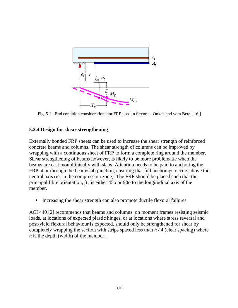
[16] [reproduced in [19] [Figure 5.1] be used to determine end conditions in flexure.
120
Fig. 5.1 - End condition considerations for FRP used in flexure – Onken and vom Bera [ 16 ]
5.2.4 Design for shear strengthening
Externally bonded FRP sheets can be used to increase the shear strength of reinforced
concrete beams and columns. The shear strength of columns can be improved by
wrapping with a continuous sheet of FRP to form a complete ring around the member.
Shear strengthening of beams however, is likely to be more problematic when the
beams are cast monolithically with slabs. Attention needs to be paid to anchoring the
FRP at or through the beam/slab junction, ensuring that full anchorage occurs above the
neutral axis (ie, in the compression zone). The FRP should be placed such that the
principal fibre orientation, β , is either 45o or 90o to the longitudinal axis of the
member.
• Increasing the shear strength can also promote ductile flexural failures.
ACI 440 [2] recommends that beams and columns on moment frames resisting seismic
loads, at locations of expected plastic hinges, or at locations where stress reversal and
post-yield flexural behaviour is expected, should only be strengthened for shear by
completely wrapping the section with strips spaced less than h / 4 (clear spacing) where
h is the depth (width) of the member .

121
• Types of shear wraps :-
Fig. 5.2 - types of wrapping systems for shear reinforcement
Complete wrapping of the FRP around the section is the most efficient, followed by the
3-sided and the 2-sided wrap. In beam applications, especially T-beams where the
neutral axis is mostly found in the slab portion of the beam, it is necessary to ensure
the FRP is anchored in the compression zone (above the neutral axis). This is achieved
by passing the FRP strip through slots cut in the slab and anchoring it on the top of the
slab. Alternatively, anchors capable of transmitting the force from the FRP through
into and beyond the mild steel reinforcement stirrups, can be used, if proper detailing
of the load transfer from FRP to anchor is considered. The 3-sided and 2-sided
wraps should be used with absolute caution.
The UK Concrete Society TR 55 [1], German General Guideline [3] and ACI 440
(draft) [2] all treat the shear situation differently. Depending on whether you are in an
area where ACI 318 is used (global safety factors), or in Europe (partial material
reduction factors), the requirements are quite different. Designers are recommended to
study the appropriate code/guidelines, for detailed use .
Current research on shear strengthening with bonded FRP suggests that, as with
conventional reinforced concrete, shear failure will occur due to two basic mechanisms,
diagonal tension (resisted by shear stirrups) and diagonal compression (resisted by
inclined concrete compression struts in tie and strut model).
For a detailed summary of the requirements of each of the three guidelines [19] should
be consulted. This summary is not exhaustive and readers are advised to consult the
appropriate document they are working with.
The authors recommend that designers use a method which makes sure connection of
the FRP shear strengthening members follow the internal truss structure (Figure 5.3). In
most cases, this will mean the anchorage of the FRP strips will be located within the
compression zone of the concrete.

122
Fig. 5.3 - Connection of the FRP shear strengthening to the internal truss structure.
Spacing of FRP Laminate Strips As in the case with steel shear reinforcement, the
spacing of FRP laminate strips should not be so wide as to allow the full formation of a
diagonal crack without intercepting a strip. For this reason, if laminate strips are used,
their spacing should not exceed the lesser of 0.8d and w f + d / 4 where:
d the effective depth of the beam and w f the width of F.R.P laminate strips .
5.2.5 Design for Axial Load Enhancement Retrofitting to enhance the axial compressive strength of concrete members using FRP
material is commonly used. By wrapping a column with an FRP jacket, the shear,
moment and axial load capacity, as well as the ductility, are improved. The column is
wrapped with the FRP fibers in the hoop direction and this provides significant
confinement to the concrete, thus leading to improvement in performance.
GFRP and CFRP are both very effective in enhancing axial performance. Creep of
GFRP is not a concern with column wrapping because under normal service loads, the
jacket remains virtually stress free.
Both circular and rectangular columns are able to be enhanced with FRP jackets. The
most effective situation is the circular or oval jacket, but reasonable enhancement of
rectangular columns is achievable, although less than that of square or circular
columns.
123
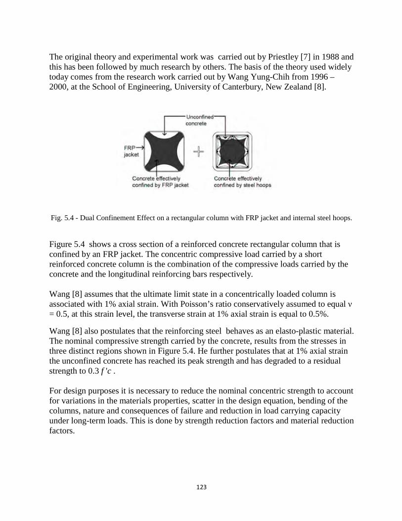
The original theory and experimental work was carried out by Priestley [7] in 1988 and
this has been followed by much research by others. The basis of the theory used widely
today comes from the research work carried out by Wang Yung-Chih from 1996 –
2000, at the School of Engineering, University of Canterbury, New Zealand [8].
Fig. 5.4 - Dual Confinement Effect on a rectangular column with FRP jacket and internal steel hoops.
Figure 5.4 shows a cross section of a reinforced concrete rectangular column that is
confined by an FRP jacket. The concentric compressive load carried by a short
reinforced concrete column is the combination of the compressive loads carried by the
concrete and the longitudinal reinforcing bars respectively.
Wang [8] assumes that the ultimate limit state in a concentrically loaded column is
associated with 1% axial strain. With Poisson’s ratio conservatively assumed to equal ν
= 0.5, at this strain level, the transverse strain at 1% axial strain is equal to 0.5%.
Wang [8] also postulates that the reinforcing steel behaves as an elasto-plastic material.
The nominal compressive strength carried by the concrete, results from the stresses in
three distinct regions shown in Figure 5.4. He further postulates that at 1% axial strain
the unconfined concrete has reached its peak strength and has degraded to a residual
strength to 0.3 f 'c .
For design purposes it is necessary to reduce the nominal concentric strength to account
for variations in the materials properties, scatter in the design equation, bending of the
columns, nature and consequences of failure and reduction in load carrying capacity
under long-term loads. This is done by strength reduction factors and material reduction
factors.
124
The compressive load carried by the concrete results from the loads sustained by three
distinct regions, viz, the unconfined concrete region, the effective area confined by the
FRP jacket and the effective area of the concrete confined by both the FRP jacket and
the steel stirrups. Hence the entire uni-axial stress-strain relationship for a
concentrically loaded column wrapped with an FRP jacket can be obtained if the
constitutive stress strain relation ships for each of the regions and for the reinforcing
steel are known. The determination of the compressive strength of the confined
concrete and the evaluation of the lateral confining pressure due to the elastic jacket
and internal reinforcing stirrups is then able to be calculated [8].
5.2.6 Conclusions on design aspects
It is not possible, in the space allocated for a paper such as this, to provide a total
picture of the state-of-the-art of this technology. However, suffice it to say that the use
of FRP materials will greatly increase in the coming years. They have served their
apprentiship and have proven to be economical and beneficial substitutes for the
alternative methods of strengthening. The fact that we continue to upgrade our
structures to increase ductility, load carrying capacity and seismic resistance will
dictate that these materials will continue to be a strong participant in such activities.
New Zealand has lead the way for over 30 years in concrete technology – is it not time
now for NZ in concrete technology – is it not time now for NZ to decide it must
produce its own set of guidelines for use in this country? This is something the industry
should carefully consider.
125
5.3 Strengthening of Reinforced Concrete Structures with CFRP
Laminates
5.3.1 Definition
Rehabilitation and strengthening of existing concrete structures has come more and more in focus during the last decade. All over the world there are structures intended for living and transportation. The structures are of varying quality and function, but they are all ageing and deteriorating over time. Of the structures needed in 20 years from now about 85-90 % of these are already built. Some of these structures will need to be replaced since they are in such bad condition. However, it is not only the deterioration processes that make upgrading necessary, errors can have been made during the design or construction phase so that the structure needs to be strengthened before it can be used. New and increased demands from the transportation sector can be another reason for strengthening. If any of these situations should arise it needs to be determined whether it is more economical to strengthen the existing structure or to replace it. There exist many different ways of strengthening an existing concrete structure, such as sprayed concrete, different types of concrete overlays, pre-tensioned cables placed on the outside of the structure, just to mention a few. A strengthen method that was used quite extensively during the mid 1970s is steel Plate Bonding, this method has gained renaissance the last decade, but now as FRP (Fibre Reinforced Polymers) Plate Bonding. This technique may be defined as one in which a composite plate or sheet of relatively small thickness is bonded with an epoxy adhesive to in most cases a concrete structure in order to improve its structural behaviour and strength. The sheets or plates do not require much space and give a composite action between the adherents. Extensive research and laboratory testing has been carried out all over the world and at many different locations. These investigations show that the method is very effective and a considerable strengthening effect can be achieved At Luleå University of Technology, research is taking place in the field of CFRP-Strengthening, i.e., the process of strengthening concrete members by bonding CFRP (Fibre Reinforced Polymer) plates or sheets to their surfaces. The research work started in 1988, then with steel plates and is today continuing with FRP materials. Both comprehensive experimental and theoretical work has been undertaken. The laboratory tests include strengthening for bending as well as for shear and torsion. In addition several full-scale tests have been performed. In 1996 work with NSMR (Near Surface Mounted Reinforcement) started. Pilot tests were performed and the benefits compared to traditional Plate Bonding were found to be many.
In this part a background and need to the use of NSMR is discussed. Also
126
laboratory tests and theory for concrete beams strengthened with near surface mounted CFRP reinforcement are presented briefly. In addition, the use of NSMR in field applications is discussed and a field application is presented.
5.3.2 Strengthening Concrete Structures in general
As most of us know, concrete is a building material with a high compressive strength and a poor tensile strength. A beam without any form of reinforcement will crack and fail when subjected to a relatively small load. The failure occurs suddenly in most cases and in a brittle manner. The most common way to reinforce a concrete structure is to use steel reinforcing bars that are placed in the structure before the concrete is cast. Since a concrete structure usually has a very long life, it is quite common that the demands on the structure change with time. The structures may have to carry larger loads at a later date or fulfill new standards. In extreme cases, a structure may need to be repaired due to an accident. Another reason can be that errors have been made during the design or construction phase so that the structure needs to be strengthened before it can be used. If any of these situations should arise it needs to be determined whether it is more economical to strengthen the structure or to replace it. It should also be remembered that over the past decade, the issue of deteriorating infrastructure has become a topic of critical importance in Europe, and to an equal extent in the United States and Japan. The deterioration of decks, superstructure elements and columns can be traced to reasons ranging from ageing and environmentally induced degradation to poor initial construction and lack of maintenance. Added to the problems of deterioration, are the issues related to the needs for higher load ratings and the increased number of lanes to accommodate the ever-increasing traffic flow on the major arteries. As an overall result, a significant portion of our infrastructure is currently either structurally or functionally deficient. Beyond the costs and visible consequences associated with continuous retrofit and repair of such structural components, are the real consequences related to losses in production and overall economies related to time and resources caused by delays and detours. As we move into the twenty-first century, the renewal of our lifelines becomes a critical issue.
However, to keep a structure at the same performance level it needs to be maintained at predestined time intervals. If lack of maintenance has lowered the performance level of the structure, need for repair up to the original performance level can be required. In cases when higher performance levels are needed, upgrading can be necessary. Performance level means load carrying capacity, durability, function or aesthetic appearance. Upgrading refers to strengthening, increased durability, and
127
change of function or improved aesthetic appearance. In this book, mainly strengthening is discussed.
Restoration, reparation and reinforcement of old concrete structures are becoming
increasingly common. If one considers the capital that has been invested in existing
infrastructures, then it is not always economically viable to replace an existing
structure with a new one. The challenge must be taken to develop relatively simple
measures such as rebuilding, restoration, reparation and reinforcement that can be used
to prolong the life of structures. An example of reinforcement would be strengthening
an existing structure to carry greater loads. This places a great demand on both
consultants and contractors. There are difficulties in assessing the most suitable
method for an actual subject; as for example, two identical columns within the same
structure can have totally different life spans depending on their individual
microclimate. It is therefore important to analyse the problem thoroughly to be able to
select the correct measure. The choice of an unsuitable reparation method can even
deteriorate the structure’s function. In the cases where reparation is appropriate, the
intention should be to increase durability or load-bearing capacity. In comparison to
building a new structure, strengthening an existing one is often more complicated
since the structural conditions are already set. It can also be a problem to reach the
areas that need to be strengthened. This is generally the case for traditional methods
such as for example different kinds of reinforced overlays, shotcrete or post tensioned
cables placed on the outside of the structure which normally need much space.
In recent years the development of the plate bonding repair technique has shown to be
applicable to many existing strengthening problems in the building industry, not
only for strengthening but also in cases of rebuilding and when mistakes have
been made in the design or construction phase. This technique may be defined as
one in which composite sheets or plates of relatively small thickness are bonded
with an epoxy adhesive to, in most cases, a concrete structure to improve its structural
behaviour and strength. The sheets or plates do not require much space and give a
composite action between the adherents. The adhesive that is used to bond the fabric
or the laminate to the concrete surface is a hardy two-component epoxy adhesive,
which together with the fibre then becomes a plastic composite on the surface of the
structure. The old structure and the new bonded material create a structural
relationship that has a greater strength than the original structure.
The question must be asked why advanced composites are suitable for civil engineering applications. Fibre reinforced polymer matrix composite materials have a number of advantages when compared to traditional construction materials such as steel, wood and concrete. Fibre reinforced polymers (FRPs), offer excellent corrosion resistance to environmental agents
128
as well as the advantages of high stiffness-to-weight and strength-to-weight ratios when compared to conventional construction materials. Other advantages of FRPs include low thermal expansion, good fatigue performance and damage tolerance, non-magnetic properties, the ease of transportation and handling, low energy consumption during fabrication of raw material and structure, and the potential for real time monitoring. Perhaps the biggest advantage of FRPs is tailorability. Reinforcement can be arranged according to the loading conditions so that a FRP structure or a component can be optimised for performance. The apparent high cost of FRPs compared to conventional materials has been a major unfavourable restraint. However, a direct comparison of the unit price basis may not be appropriate. When installation is included in the cost comparison, FRPs can be competitive with conventional materials. The lightweight of FRPs reduces transportation expenses and allows some prefabrication to take place at the factory, which reduces time at the job site. If the comparisons include life cycle costs, FRPs can have a significant advantage. The unique properties of FRPs, like high corrosion resistance, make the life cycle cost lower than that of conventional materials. In many cases a composite structure can last much longer than conventional materials, thus ensuring a lower life-cycle cost in many cases. Also, increasing demand will drive down the cost of FRP. The introduction of fibre reinforced polymers in civil engineering structures has progressed at a very rapid rate in recent years. The basic ideas related to the use of FRPs for structural strengthening, along with examples of application, have been presented by Triantafillou, (1998). The past and potential future use of FRP strengthening and rehabilitation have also recently been documented in many conference proceedings (Meier and Betti, 1997, Täljsten, 1997, Benmokrane and Rahman, 1998), keynote lectures (Maruyama, 1997, Neale and Labossiére, 1997) and journal articles (Thomas, 1998).
The most common way to strengthen structures has been for bending but shear
strengthening is also often needed. The most common method has been to place sheets
or laminates on the surface of the structure, however, further development of the plate
bonding method has shown that it is favourable to place the laminates in the concrete
cover of the structure. This method can be designated NSMR or Near Surface Mounted
Reinforcement.
5.3.3 NSMR - a short Introduction The use of Near Surface Mounted Reinforcement for concrete structures is
129
not a new invention. A type of NSMR has been used since the 1940s, where steel reinforcement was placed in slots in the concrete cover or in additional concrete cover that was cast to the structure. A type of steel NSMR has been used since the invention of shotcrete. However, in these applications it was often difficult to get good bond to the original structures surface, and in some cases, it was not always easy to cast the concrete around the whole steel reinforcing bars. From the 1960s the development of strong adhesives, such as epoxies, for the construction industry moved the method further ahead by bonding the steel bars in sawed slots in the concrete cover. However, due to the corrosion sensitivity of steel bars an additional concrete cover was needed. For these applications epoxy coated steel bars have also been used, however, it has been shown over time that epoxy coated steel bars are not always corrosion resistant for various reasons that not will be discussed here. The use of steel NSMR has not been a great success. Nevertheless, by using CFRP NSMR some of these drawbacks presented can be overcome. First of all, CFRP NSMR does not corrode, so thick concrete covers are not needed. Secondly, the CFRP laminate can be tailor-made for near surface applications, thirdly the lightweight of the CFRP laminates makes them easy to mount. Furthermore, depending on the form of the laminate air voids behind the laminates can be avoided. Both epoxies and systems using high quality cement mortar can be used. However, before proceeding, a short description of how to undertake a strengthening work with NSMR will be given. In practical execution the following steps must in general be performed during strengthening:
• Sawing up slots in the concrete cover, depth depending on product used and depth of concrete cover.
• Careful cleaning of the slots after sawing, high-pressurised water, approximately 100 - 150 bars, is recommended. No saw mud allowed in the slot
• If an epoxy system is used, the slot must be dry before bonding. If a cement system is used it is mostly recommended that the existing surfaces are wet at the time of concrete mortar casting.
• Adhesive is applied in the slot or with a cement system; cement mortar is applied in the slot.
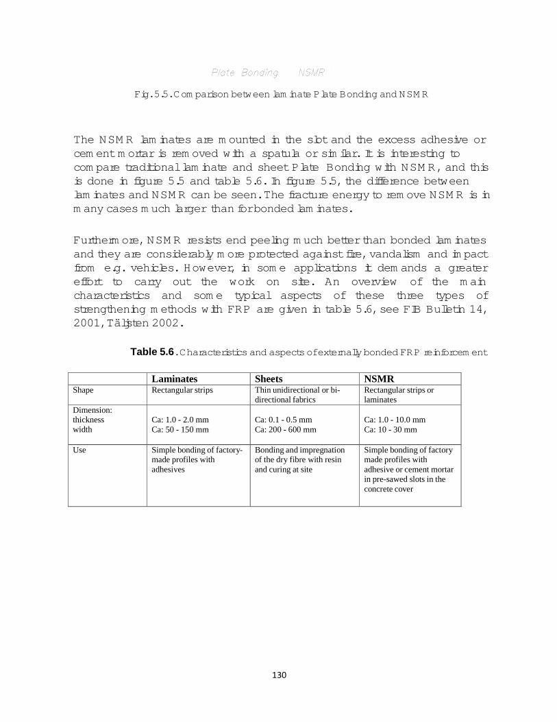
130
Fig. 5.5. Comparison between laminate Plate Bonding and NSMR
The NSMR laminates are mounted in the slot and the excess adhesive or cement mortar is removed with a spatula or similar. It is interesting to compare traditional laminate and sheet Plate Bonding with NSMR, and this is done in figure 5.5 and table 5.6. In figure 5.5, the difference between laminates and NSMR can be seen. The fracture energy to remove NSMR is in many cases much larger than for bonded laminates.
Furthermore, NSMR resists end peeling much better than bonded laminates and they are considerably more protected against fire, vandalism and impact from e.g. vehicles. However, in some applications it demands a greater effort to carry out the work on site. An overview of the main characteristics and some typical aspects of these three types of strengthening methods with FRP are given in table 5.6, see FIB Bulletin 14, 2001, Täljsten 2002.
Table 5.6. Characteristics and aspects of externally bonded FRP reinforcement
Laminates Sheets NSMR
Shape Rectangular strips Thin unidirectional or bi-
directional fabrics
Rectangular strips or
laminates
Dimension:
thickness
width
Ca: 1.0 - 2.0 mm
Ca: 50 - 150 mm
Ca: 0.1 - 0.5 mm
Ca: 200 - 600 mm
Ca: 1.0 - 10.0 mm
Ca: 10 - 30 mm
Use
Simple bonding of factory-
made profiles with
adhesives
Bonding and impregnation
of the dry fibre with resin
and curing at site
Simple bonding of factory
made profiles with
adhesive or cement mortar
in pre-sawed slots in the
concrete cover
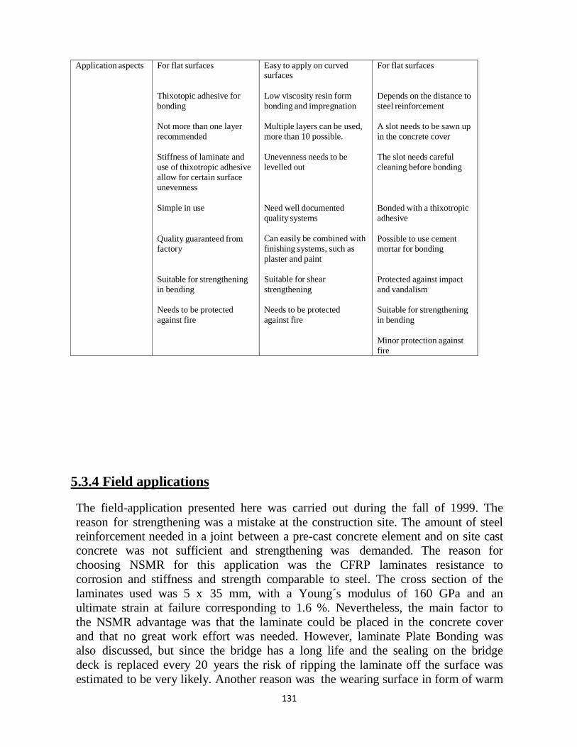
131
Application aspects For flat surfaces
Thixotopic adhesive for
bonding
Not more than one layer
recommended
Stiffness of laminate and
use of thixotropic adhesive
allow for certain surface
unevenness
Simple in use
Quality guaranteed from
factory
Suitable for strengthening
in bending
Needs to be protected
against fire
Easy to apply on curved surfaces
Low viscosity resin form
bonding and impregnation
Multiple layers can be used,
more than 10 possible.
Unevenness needs to be
levelled out
Need well documented
quality systems
Can easily be combined with
finishing systems, such as
plaster and paint
Suitable for shear
strengthening
Needs to be protected
against fire
For flat surfaces
Depends on the distance to
steel reinforcement
A slot needs to be sawn up
in the concrete cover
The slot needs careful
cleaning before bonding
Bonded with a thixotropic
adhesive
Possible to use cement
mortar for bonding
Protected against impact
and vandalism
Suitable for strengthening
in bending
Minor protection against
fire
5.3.4 Field applications
The field-application presented here was carried out during the fall of 1999. The
reason for strengthening was a mistake at the construction site. The amount of steel
reinforcement needed in a joint between a pre-cast concrete element and on site cast
concrete was not sufficient and strengthening was demanded. The reason for
choosing NSMR for this application was the CFRP laminates resistance to
corrosion and stiffness and strength comparable to steel. The cross section of the
laminates used was 5 x 35 mm, with a Young´s modulus of 160 GPa and an
ultimate strain at failure corresponding to 1.6 %. Nevertheless, the main factor to
the NSMR advantage was that the laminate could be placed in the concrete cover
and that no great work effort was needed. However, laminate Plate Bonding was
also discussed, but since the bridge has a long life and the sealing on the bridge
deck is replaced every 20 years the risk of ripping the laminate off the surface was
estimated to be very likely. Another reason was the wearing surface in form of warm
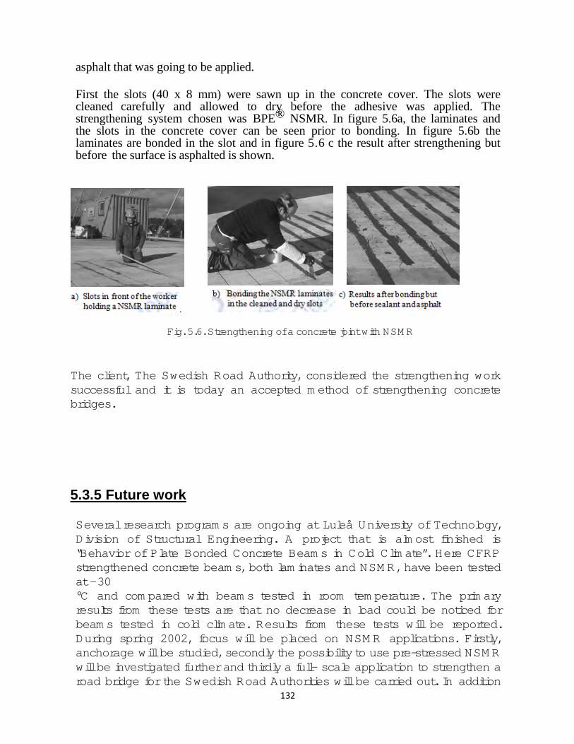
132
asphalt that was going to be applied.
First the slots (40 x 8 mm) were sawn up in the concrete cover. The slots were cleaned carefully and allowed to dry before the adhesive was applied. The strengthening system chosen was BPE® NSMR. In figure 5.6a, the laminates and the slots in the concrete cover can be seen prior to bonding. In figure 5.6b the laminates are bonded in the slot and in figure 5.6 c the result after strengthening but before the surface is asphalted is shown.
.
Fig. 5.6. Strengthening of a concrete joint with NSMR
The client, The Swedish Road Authority, considered the strengthening work successful and it is today an accepted method of strengthening concrete bridges.
5.3.5 Future work Several research programs are ongoing at Luleå University of Technology, Division of Structural Engineering. A project that is almost finished is “Behavior of Plate Bonded Concrete Beams in Cold Climate”. Here CFRP strengthened concrete beams, both laminates and NSMR, have been tested at - 30 °C and compared with beams tested in room temperature. The primary results from these tests are that no decrease in load could be noticed for beams tested in cold climate. Results from these tests will be reported. During spring 2002, focus will be placed on NSMR applications. Firstly, anchorage will be studied, secondly the possibility to use pre-stressed NSMR will be investigated further and thirdly a full- scale application to strengthen a road bridge for the Swedish Road Authorities will be carried out. In addition

133
ongoing research regarding shear and torsion strengthening will be continued.

134
133
5.4 Strengthening Techniques of Reinforced Concrete Columns
Using Fiber Reinforced Polymeric Materials
5.4.1 Why need to strengthening columns?
Fiber reinforced composite materials are becoming more frequently used in
civil engineering structures. One of the most practical applications of these
new materials concerns the strengthening of reinforced concrete columns
by means of confinement with fibre composite sheets. In the literature,
various theoretical models have been proposed to describe the behaviour of
confined concrete columns. The principal advantages of this technique are
the high strength-to-weight ratio, good fatigue properties, non-corroding
characteristics of the fibre reinforced polymers (FRP), and the facility of its
application. The maximum efficiency of confining systems using FRP
materials is reached in case of columns with circular cross-section and is
explained by the fact that the entire section of the column is involved into
the confinement effect. Rectangular confining reinforcement is less
efficient as the confinement action is mostly located at the corners This
paper reveals the most utilized techniques of performing composite
confining systems for reinforced concrete columns, with their advantages
and also disadvantages.
5.4.2. Generic Information :-
Over the years, engineers have used different methods and techniques to
retrofit existing structures by providing external confining stresses. For the
past few years, the concept of jacketing has been investigated to provide such
forces. Externally applied jackets have been used as a reinforcement to
contain concrete for different reasons. Engineers have used traditional
materials such as wood, steel, and concrete to confine and improve the
structural behavior of concrete members [7].
Section enlargement is one of the methods used in retrofitting concrete
members. Enlargement is the placement of reinforced concrete jacket around
the existing structural member to achieve the desired section properties and
performance. The main disadvantages of such system are the increase in the
column size obtained after the jacket is constructed and the need to construct a
new formwork.
Steel jacketing has been proven to be an effective technique to enhance the
seismic performance of old bridge columns. The steel jacket is manufactured
in two shell pieces and welded in the field around the column.
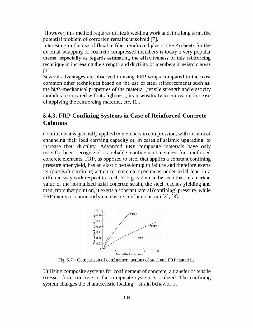
134
However, this method requires difficult welding work and, in a long term, the
potential problem of corrosion remains unsolved [7].
Interesting in the use of flexible fiber reinforced plastic (FRP) sheets for the
external wrapping of concrete compressed members is today a very popular
theme, especially as regards estimating the effectiveness of this reinforcing
technique in increasing the strength and ductility of members in seismic areas
[1].
Several advantages are observed in using FRP wraps compared to the most
common other techniques based on the use of steel reinforcements such as:
the high-mechanical properties of the material (tensile strength and elasticity
modulus) compared with its lightness; its insensitivity to corrosion; the ease
of applying the reinforcing material, etc. [1].
5.4.3. FRP Confining Systems in Case of Reinforced Concrete
Columns
Confinement is generally applied to members in compression, with the aim of
enhancing their load carrying capacity or, in cases of seismic upgrading, to
increase their ductility. Advanced FRP composite materials have only
recently been recognized as reliable confinement devices for reinforced
concrete elements. FRP, as opposed to steel that applies a constant confining
pressure after yield, has an elastic behavior up to failure and therefore exerts
its (passive) confining action on concrete specimens under axial load in a
different way with respect to steel. In Fig. 5.7 it can be seen that, at a certain
value of the normalized axial concrete strain, the steel reaches yielding and
then, from that point on, it exerts a constant lateral (confining) pressure, while
FRP exerts a continuously increasing confining action [3], [8].
Fig. 5.7 – Comparison of confinement actions of steel and FRP materials.
Utilizing composite systems for confinement of concrete, a transfer of tensile
stresses from concrete to the composite system is realized. The confining
system changes the characteristic loading – strain behavior of
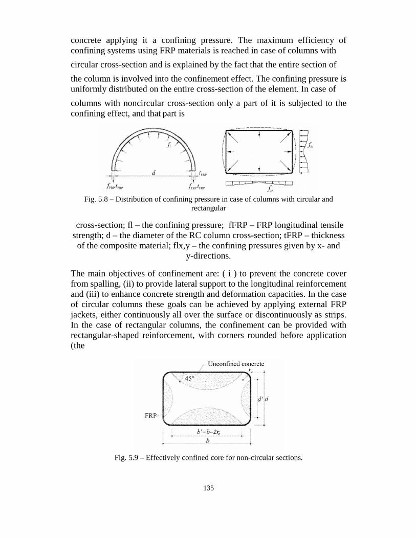
135
concrete applying it a confining pressure. The maximum efficiency of
confining systems using FRP materials is reached in case of columns with
circular cross-section and is explained by the fact that the entire section of
the column is involved into the confinement effect. The confining pressure is
uniformly distributed on the entire cross-section of the element. In case of
columns with noncircular cross-section only a part of it is subjected to the
confining effect, and that part is
Fig. 5.8 – Distribution of confining pressure in case of columns with circular and
rectangular
cross-section; fl – the confining pressure; fFRP – FRP longitudinal tensile
strength; d – the diameter of the RC column cross-section; tFRP – thickness
of the composite material; flx,y – the confining pressures given by x- and
y-directions.
The main objectives of confinement are: ( i ) to prevent the concrete cover
from spalling, (ii) to provide lateral support to the longitudinal reinforcement
and (iii) to enhance concrete strength and deformation capacities. In the case
of circular columns these goals can be achieved by applying external FRP
jackets, either continuously all over the surface or discontinuously as strips.
In the case of rectangular columns, the confinement can be provided with
rectangular-shaped reinforcement, with corners rounded before application
(the
Fig. 5.9 – Effectively confined core for non-circular sections.
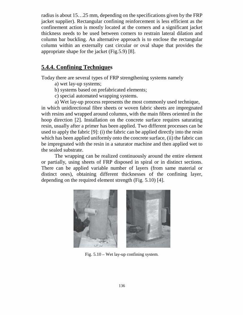
136
radius is about 15…25 mm, depending on the specifications given by the FRP
jacket supplier). Rectangular confining reinforcement is less efficient as the
confinement action is mostly located at the corners and a significant jacket
thickness needs to be used between corners to restrain lateral dilation and
column bar buckling. An alternative approach is to enclose the rectangular
column within an externally cast circular or oval shape that provides the
appropriate shape for the jacket (Fig.5.9) [8].
5.4.4. Confining Techniques
Today there are several types of FRP strengthening systems namely
a) wet lay-up systems;
b) systems based on prefabricated elements;
c) special automated wrapping systems.
a) Wet lay-up process represents the most commonly used technique,
in which unidirectional fibre sheets or woven fabric sheets are impregnated
with resins and wrapped around columns, with the main fibres oriented in the
hoop direction [2]. Installation on the concrete surface requires saturating
resin, usually after a primer has been applied. Two different processes can be
used to apply the fabric [9]: (i) the fabric can be applied directly into the resin
which has been applied uniformly onto the concrete surface, (ii) the fabric can
be impregnated with the resin in a saturator machine and then applied wet to
the sealed substrate.
The wrapping can be realized continuously around the entire element
or partially, using sheets of FRP disposed in spiral or in distinct sections.
There can be applied variable number of layers (from same material or
distinct ones), obtaining different thicknesses of the confining layer,
depending on the required element strength (Fig. 5.10) [4].
Fig. 5.10 – Wet lay-up confining system.
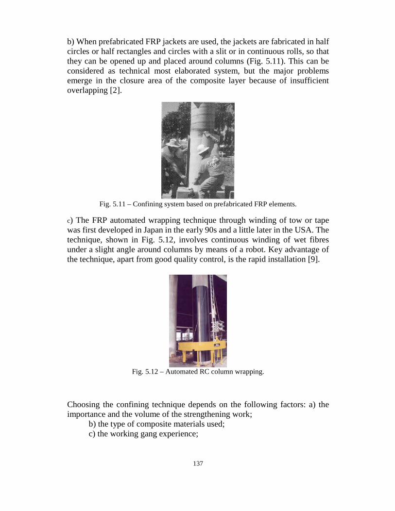
137
b) When prefabricated FRP jackets are used, the jackets are fabricated in half
circles or half rectangles and circles with a slit or in continuous rolls, so that
they can be opened up and placed around columns (Fig. 5.11). This can be
considered as technical most elaborated system, but the major problems
emerge in the closure area of the composite layer because of insufficient
overlapping [2].
Fig. 5.11 – Confining system based on prefabricated FRP elements.
c) The FRP automated wrapping technique through winding of tow or tape
was first developed in Japan in the early 90s and a little later in the USA. The
technique, shown in Fig. 5.12, involves continuous winding of wet fibres
under a slight angle around columns by means of a robot. Key advantage of
the technique, apart from good quality control, is the rapid installation [9].
Fig. 5.12 – Automated RC column wrapping.
Choosing the confining technique depends on the following factors: a) the
importance and the volume of the strengthening work;
b) the type of composite materials used;
c) the working gang experience;
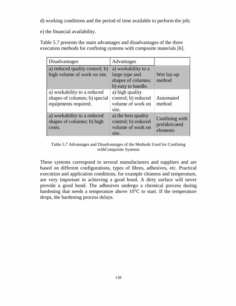
138
d) working conditions and the period of time available to perform the job;
e) the financial availability.
Table 5.7 presents the main advantages and disadvantages of the three
execution methods for confining systems with composite materials [6].
Table 5.7 Advantages and Disadvantages of the Methods Used for Confining
withComposite Systems
These systems correspond to several manufacturers and suppliers and are
based on different configurations, types of fibres, adhesives, etc. Practical
execution and application conditions, for example cleaness and temperature,
are very important in achieving a good bond. A dirty surface will never
provide a good bond. The adhesives undergo a chemical process during
hardening that needs a temperature above 10°C to start. If the temperature
drops, the hardening process delays.
Disadvantages Advantages
a) reduced quality control; b)
high volume of work on site.
a) workability to a
large type and
shapes of columns;
b) easy to handle.
Wet lay-up
method
a) workability to a reduced
shapes of columns; b) special
equipments required.
a) high quality
control; b) reduced
volume of work on
site.
Automated
method
a) workability to a reduced
shapes of columns; b) high
costs.
a) the best quality
control; b) reduced
volume of work on
site.
Confining with
prefabricated
elements

139
5.5 Summary and Conclusion
There is no doubt that strengthening concrete structures with NSMR is an
effective method. Compared to laminate plate bonding several benefits can
be noticed, not only higher fracture energy at failure but also better
protection against fire, vandalism and impact.
The pilot tests presented in this paper show promising strengthening results
and a considerable strengthening effect could be noticed. Theory presented
covers traditional design for bending, however, more work is needed to also
cover anchorage and other types of strengthening applications.
The field application presented shows that it is easy to strengthen structures
and the method is not only time saving but also beneficial from a financial
point of view.
The following conclusions can be drawn up for the flexible bonding
system reported in this paper:
1. FRP/concrete interfaces using the flexible bonding system need much
longer anchorage length to develop fully its interfacial bond
force-transferring capacity. With a sufficient long anchorage length,
flexible bonding adhesive can achieve higher pullout capacity. FRP
sheet/concrete interfaces with normal and flexible bonding system
show big differences in their local bond stress-slip behaviours. The
flexible bonding system has lower interfacial bonding stiffness but can
ease the local stress concentration and can bear large interfacial slip
while avoiding local debonding.
2. Compared to the normal adhesive bonding, flexible bonding system
can improve the ultimate capacity of FRP strengthened RC beams. So
the high strength, an advantage of FRP, can be utilized more
efficiently. Different from those in pullout tests, the failure modes of
strengthened RC members using the flexible bonding system may
shift from the debonding of FRP/concrete interface to the ripping of
concrete covercrete. The latter mode is triggered by the yielding of
steel reinforcement rather than the stress concentration at
FRP/concrete interfaces. Therefore, the flexible bonding system
contributes a ductile failure. But the improving effects of the flexible
bonding system may be eliminated in cases of larger FRP amount and
shorter shear span.
3. Contribution of the flexible bonding system to the ultimate capacity

140
of FRP strengthened RC beams is mainly after the yielding of steel
reinforcement. Hence the flexible bonding system is appreciated for
the ultimate state strengthening rather than the serviceability
strengthening purpose.
4. The strengthened RC members using flexible bonding system have an
equal or better fatigue performance than those using normal adhesive
bonding. Compared to the normal bonding system, the flexible
bonding system contributes a smooth degradation of member stiffness
although it leads to a comparatively low initial stiffness.
5. The flexible bonding system seems particularly favourable for the
RC members with larger span. The strengthened FRP/RC composite
system can keep its integrity up to a ductile failure and gain high
strength efficiency in FRP.

141
Refrences
1- Jay H. Paul, S.E., P.E. , “Evaluation and Rehabilitation of Concrete Structures”
, Mexico City, September 11-13, 2002
2- Allen.R.T.L , "Repair Of Concrete Structures", John Willey &
Sons,1987Concrete Beams with Clamps Applied Externally, 2004
3- Allen.R.T.L ,Drive, Suite 1900 Chicago, Illinois 60606 “Evaluation and
Rehabilitation of Concrete Structures” Mexico City, September 11-13, 2002
4- Champion, S. "Failure and Repair of Concrete Structures". John Wiley & Sons
Inc. New York, 1961
5- Sidney.M.Johnson."Deterioration, Maintenance and Repair of Structures". Mc
Graw-Hill Book Company. New York, 1965.
6- Lee How Son and George C.S. Yuen. "Building Maintenance Technology.
Macmillan Distribution" Ltd. England. 1993.
7- Rob Irwin (1) and Amar Rahman (2) ," FRP Strengthening Of Concrete
Structures – Design Constraints and practical Effects on Construction Detailing" ,
John Wiley & Sons Inc. New York, 1961
8- Dr. Khair Al-Deen Isam Bsisu 1, " Retrofitting of Square Reinforced Concrete
Columns Subjected to Concentric Axial Loading with Steel Jackets" , ا���� ��� �� ���� ا�����ري ا����� �� ���� 2001 , ا�
9- Augusto Gomes and Julio Appleton , " Strengthening Design Of Concrete Beams
By Addition Of Steel Plates " , Department Of Civil Engineering , 1st , Technical
University Of Lisbon , Portugal , 2002
141
Case Studies
Columns Reinforced Concrete Strengthening of):A(Case
-:acketsUsing Reinforcement Concrete J
Project 1 -A
ain Shams (children hospital construction of Special clinics for -
) university
-:f BuildingDescription o2-A
The building consist of Four floors. ( Ground – First – Second – third –
Fourth )
The statically system is ( solid slab).
The building are supported on reinforced concrete columns. ( Skeleton
System )
The columns are in good condition with respect to ( visual inspection –
Shmedit Hammer test – core test )

142
.
Fig.A-1view for the building

143
Fig. A-2 Photos of columns before strengthening

144
Problems 3 -A
1-The Owner wanted to increase new floor which lead to increase load on
the columns and footing .
2-By Redesign and recalculate the building finding ( some columns are
unsafe due to new loads .
3- finding corrosion in some columns
Solution4 -A
1- we need to reduce the new load which come to columns by made the
new floor is ( steel material) .
2-we need to increase capacity for some columns which are unsafe
By concrete jacketing .
Fig. A-3 Photos of columns Jacketing

145
Fig.A-3 Photos of columns Jacketing
Fig. A-4 Photos of column crack repair.
146
ethod Of Application M5 -A
c.m1-Adding stirrups every ( 30- 50 )
2- remove concrete cover
3-remove corrosion from steel by wire brush .
4-paint the surface of steel bars by epoxy to protect bars from corrosion.
5- Adding sand or grout to steel surface .
6-Adding Shear Dowels to improve bonding between old and new
concrete .
7- adding new reinforcement bars in two direction .
8- placement new concrete around columns .

147
Columns Reinforced Concrete Strengthening of:)B(Case
-:ackets Jlate Using Steel P
Project 1 -B
–Elmaarag city ( of Kuaitian office construction of Office building -
) Cairo–Elmaadi
-:f BuildingDescription o2 -B
The building consist of Four floors. ( Basement – Ground – Four typical
floor)
The statically system is ( solid slab).
The building are supported on reinforced concrete columns. ( Skeleton
System )
Fig. B-1 view for the building
(Elmaarag city)

148
Fig. B-2 Columns & Axis plan
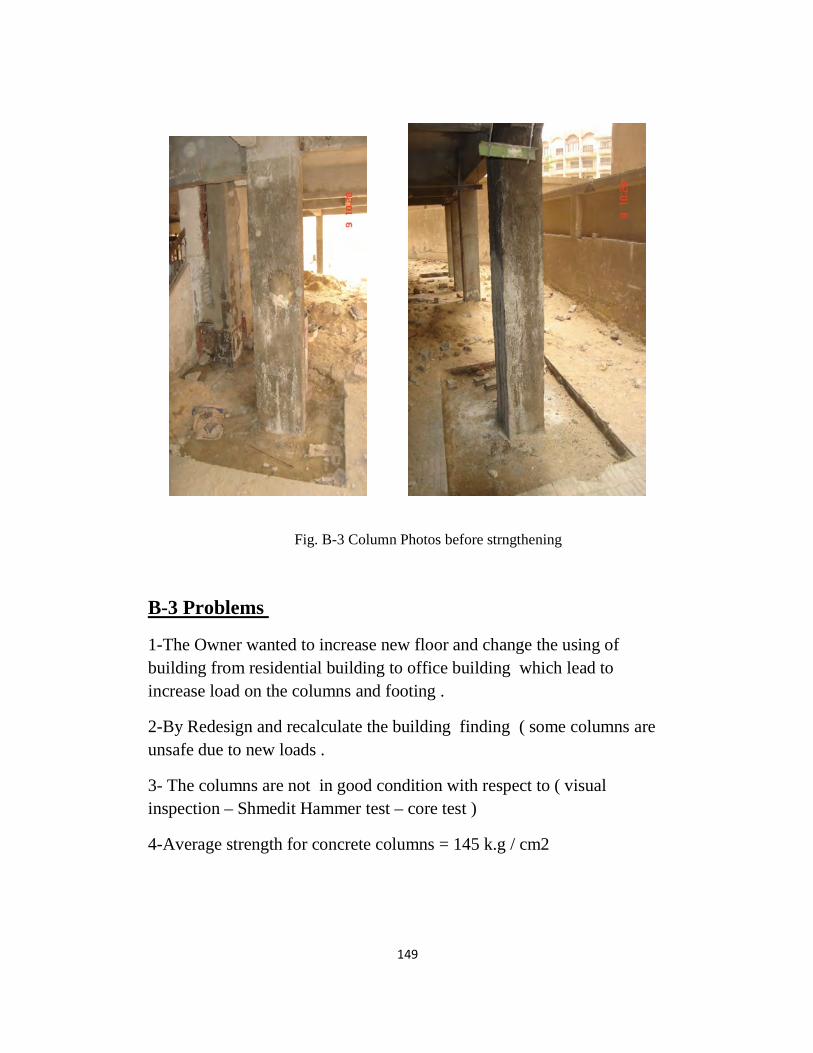
149
Fig. B-3 Column Photos before strngthening
Problems 3 -B
1-The Owner wanted to increase new floor and change the using of
building from residential building to office building which lead to
increase load on the columns and footing .
2-By Redesign and recalculate the building finding ( some columns are
unsafe due to new loads .
3- The columns are not in good condition with respect to ( visual
inspection – Shmedit Hammer test – core test )
4-Average strength for concrete columns = 145 k.g / cm2

150
Fig. B-4 Core specimens
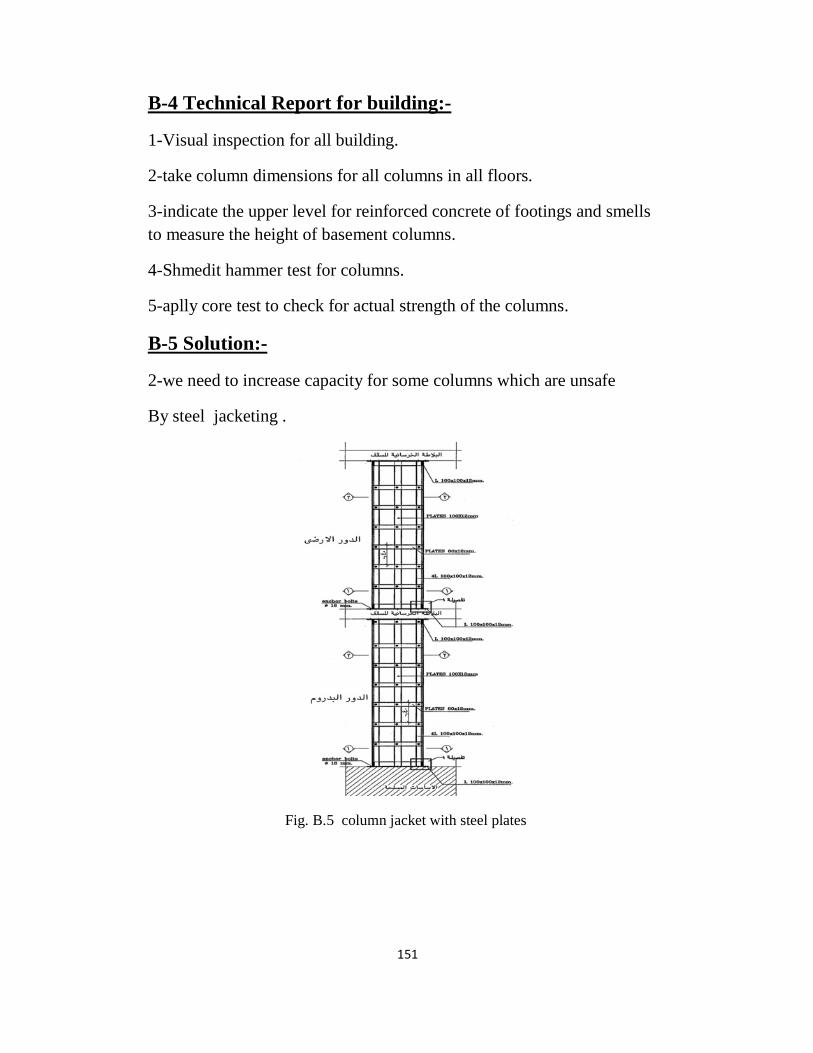
151
-:Technical Report for building4 -B
1-Visual inspection for all building.
2-take column dimensions for all columns in all floors.
3-indicate the upper level for reinforced concrete of footings and smells
to measure the height of basement columns.
4-Shmedit hammer test for columns.
5-aplly core test to check for actual strength of the columns.
-:Solution5 -B
2-we need to increase capacity for some columns which are unsafe
By steel jacketing .
Fig. B.5 column jacket with steel plates

152
Fig. B- 6 Plan Column need to strengthening
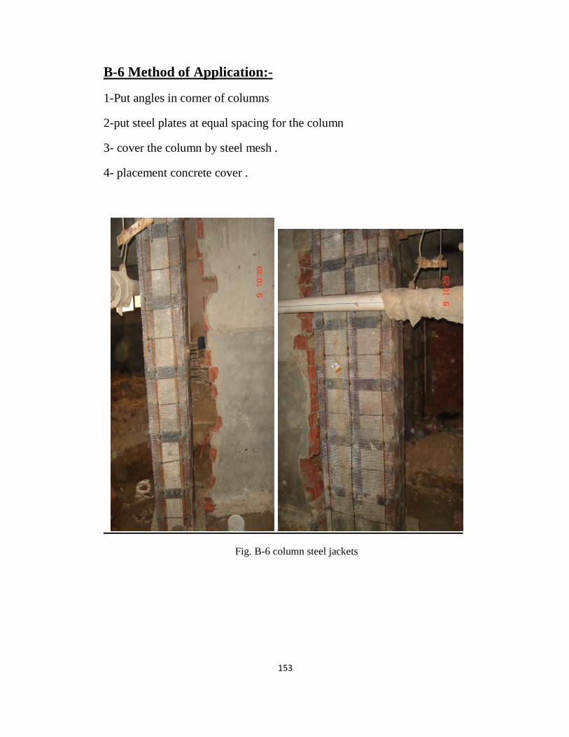
153
-:Method of Application6 -B
1-Put angles in corner of columns
2-put steel plates at equal spacing for the column
3- cover the column by steel mesh .
4- placement concrete cover .
Fig. B-6 column steel jackets
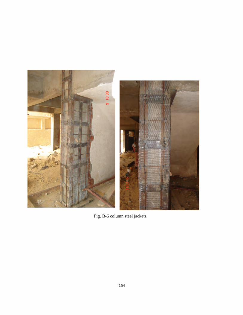
154
Fig. B-6 column steel jackets.
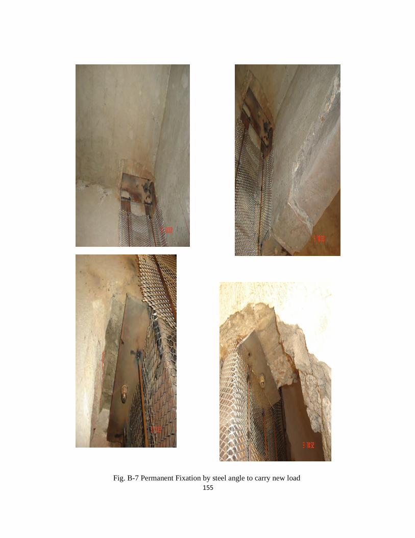
155
Fig. B-7 Permanent Fixation by steel angle to carry new load
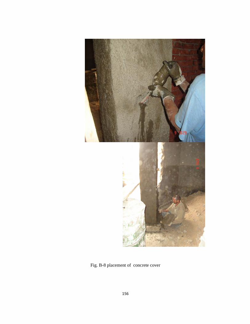
156
Fig. B-8 placement of concrete cover
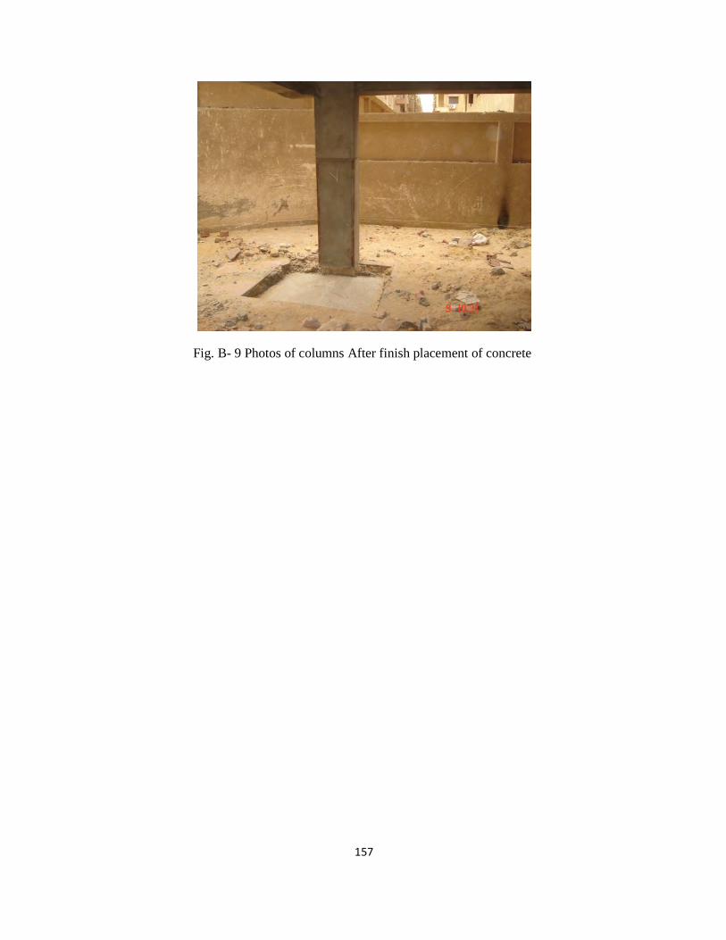
157
Fig. B- 9 Photos of columns After finish placement of concrete
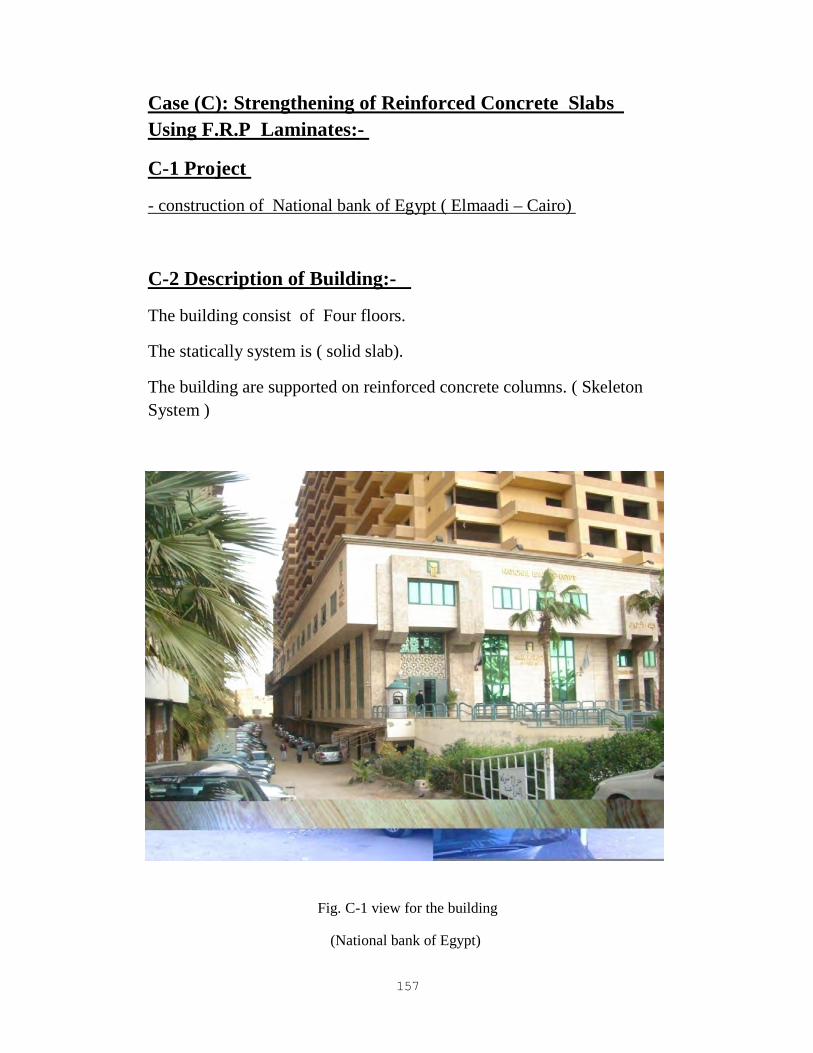
157
Strengthening of Reinforced Concrete Slabs ): C(Case
-:P Laminates.R.Using F
Project 1 -C
) Cairo–Elmaadi ( construction of National bank of Egypt -
-:f BuildingDescription o2 -C
The building consist of Four floors.
The statically system is ( solid slab).
The building are supported on reinforced concrete columns. ( Skeleton
System )
Fig. C-1 view for the building
(National bank of Egypt)
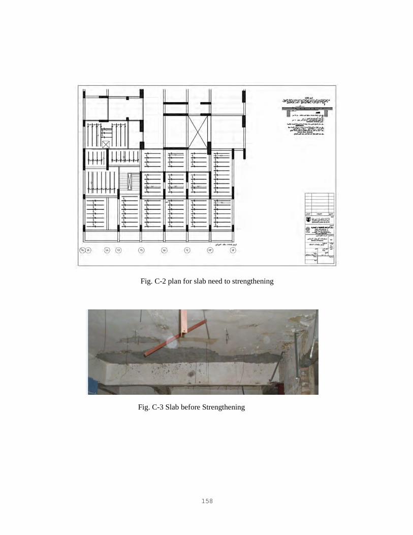
158
Fig. C-2 plan for slab need to strengthening
Fig. C-3 Slab before Strengthening
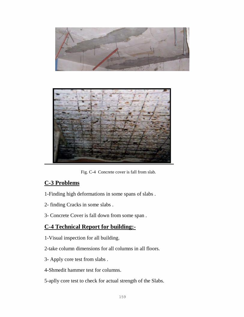
159
Fig. C-4 Concrete cover is fall from slab.
Problems3 -C
1-Finding high deformations in some spans of slabs .
2- finding Cracks in some slabs .
3- Concrete Cover is fall down from some span .
-:Technical Report for building4 -C
1-Visual inspection for all building.
2-take column dimensions for all columns in all floors.
3- Apply core test from slabs .
4-Shmedit hammer test for columns.
5-aplly core test to check for actual strength of the Slabs.

160
-:Solution5 -C
1-we need to crack injection.
2- we need to strengthening slab by CFRP material .
Method of Application 6 -C
1-Transport the load of slab by using steel column .
2-Remove concrete cover and remove corrosion from steel bars by
wire brush .
3- Paint the surface of steel by epoxy material to protect from
corrosion .
4- Placement of concrete cover .
5- paint the new surface of concrete by epoxy materials to improve
bonding between substrate concrete and CFRP material .
Fig. C-5 Crack injection for slab.

161
Fig. C- 6 Transform load from slab by Steel form
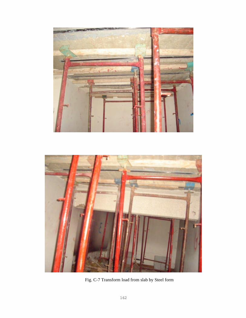
162
Fig. C-7 Transform load from slab by Steel form
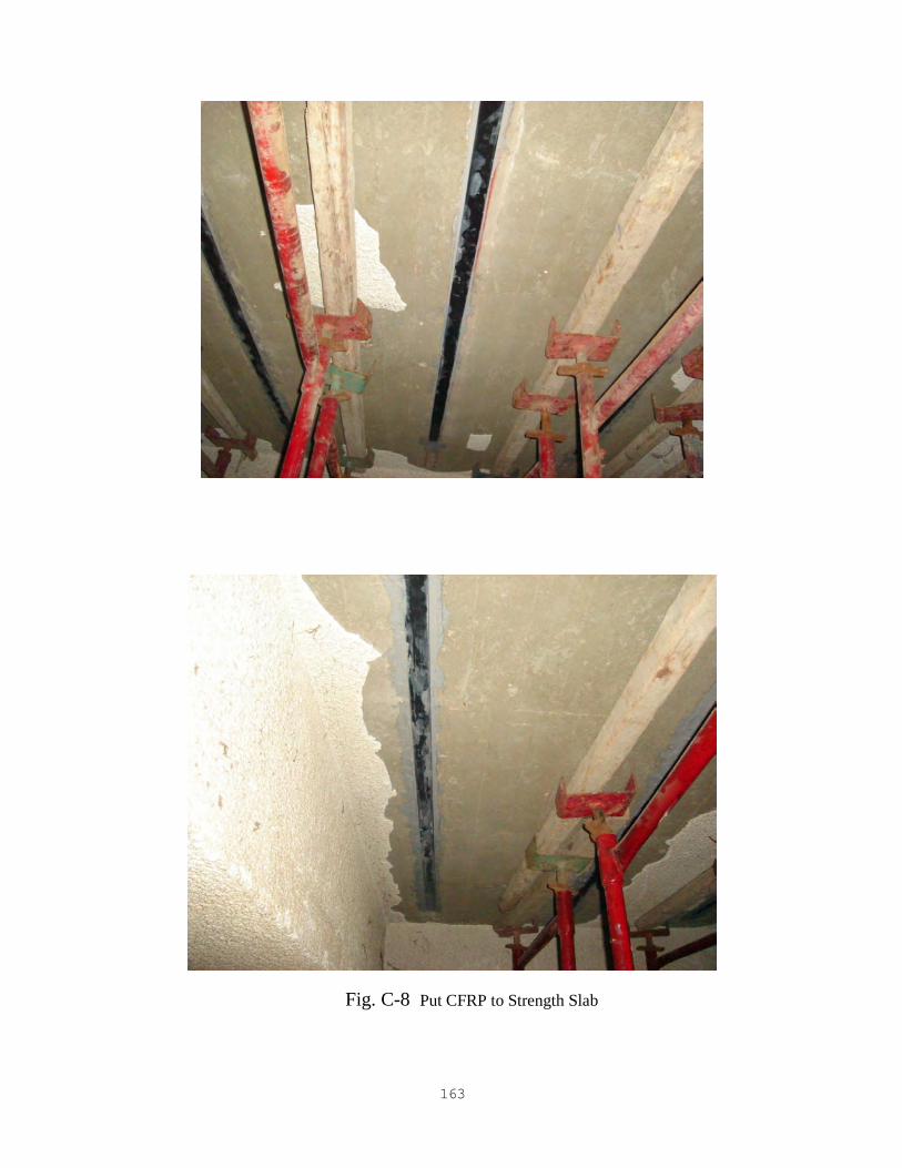
163
Fig. C-8 Put CFRP to Strength Slab
164
-:y and Conclusion Summar
1- From the review of the previous studies, it can be concluded
that epoxy injection is an easy and effective method to repair the
cracked beams. It not only reduces the deflection and control
the cracks but also slightly increases the weight of beams.
2- Furthermore this method is inexpensive and unsophisticated.
Using OPC mortar and a free flowing micro-concrete are two
possible methods to repair the beams under corrosion
conditions. However, for long term, a free flowing micro-
concrete can restore higher structural capacity and resist
chloride better under accelerated weather conditions compared
to using OPC mortar.
3-This research analyzed the various reinforced concrete
strengthening and repairing methods for reinforced concrete
Structures.
4-The experimental results that are summarized from literature
review were used to conclude the pros and cons of current
strengthening and repair methods.
5- The suggestions about retrofit and rehabilitation methods are
provided in the thesis for future work and study. The problems

165
and experiences reported in this research will be used to
improve the future repair and strengthening research.
Appendix
&�' ���� &% $#�" ا��! � :-( ���وع ا���� ا������ ������ ا������ � ��� ا����اد –
�+� "ا��*�اج)
�� ��م-1 �� . ا���� ا� ��ي ���
� ا#�د ا���"ة � ��� ا�دوار ر-2$ .
. '�"ی" م�.+ب �23 ا��0�1ن�ت ا��.��- ��,+ا�" وا���"ات �(�"ی" ار'��ع ا��"ة ا� "روم-3
�دوار ا��1(��- -4� 7,0�. اج�اء اخ( �رات ا�,�8 ا��0�1ن� ��� ا
�دوار ا��1(��- وذ�= �(,"ی� م,�وم--5� اج�اء اخ( �ر م�A@- ش��"ت ��� ا���"ة
- ی��B اج�اء اخ( �ر ا�,�8 ا��0�1ن� ��2+�A,�2 ا��,�وم- ا���ح��- �"م '�, �ا��0�1ن- و$.

166
Technical Report on Building
167
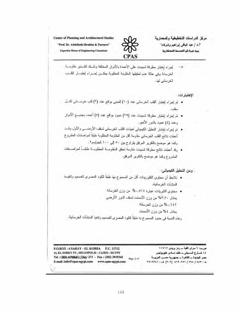
168

169
Results of Shmedit Hammer Test:-

170

171
Results of Chemical Analysis Test :-

172
Results of Core Test for Columns:-

173
Technique of Column Strengthening:-
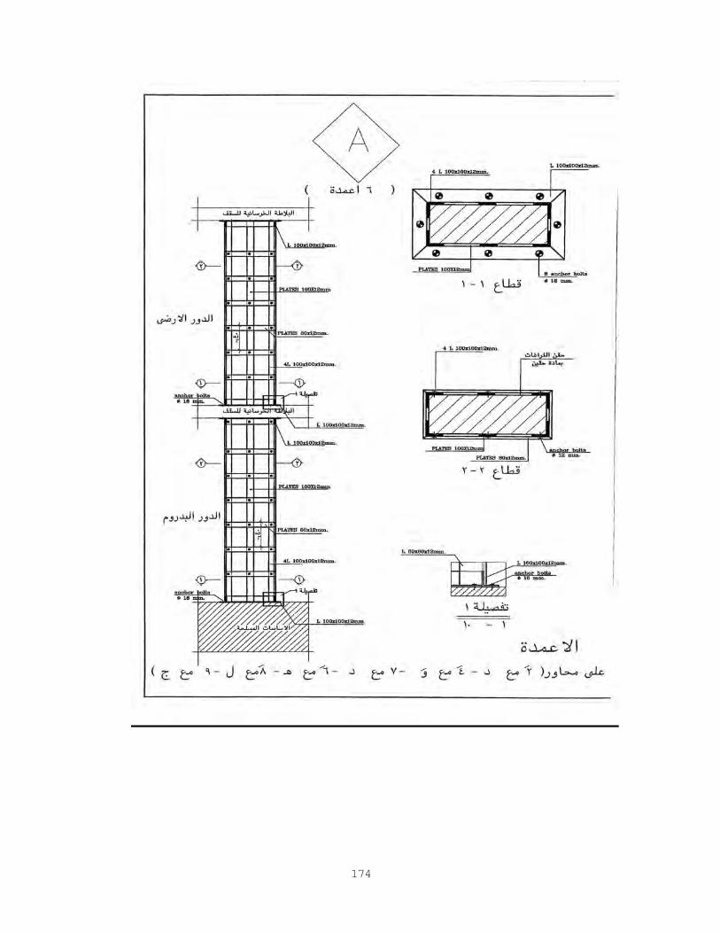
174

175

176
Technical Report on Strengthening of building:-

177