Embed Size (px)
Citation preview

Caterpillar. The difference counts.™Management Guide
Cat® Undercarriage
Undercarriage System Management
• Operating and Maintenance Tips
• Track Adjustment Procedures
• Hardware Requirements

Introduction.............................................................................................................................3
Operating and Maintenance Tips ........................................................................................4-7
Custom Track Service
Factors Affecting Wear
Operating and Maintenance Checklist
Track Adjustment Procedures ............................................................................................8-12
Elevated Sprocket Tractors without Carrier Rollers
Elevated Sprocket Tractors with Carrier Rollers
Low Sprocket Tractors and Loaders
Hydrostatic Loaders
Hydraulic Excavators
Hardware Requirements for Elevated Sprocket, Low Sprocket, and Excavator Track....13-14
Track Roller and Idler Caps
Sprocket Segment
Shoe and Link
Split Master Link
Contents
2

Work it hard. Make it last. Fix it
right. Caterpillar® Undercarriage
is designed to work and wear as
a system to reduce your
operating costs.
You make daily decisions that
impact undercarriage wear and
costs. This guide can help you
and your operators understand
how undercarriage works and
how to reduce wear and save
money. Although wear can’t
be halted, we are committed
to helping you make each
undercarriage system last
with correct operation and
maintenance.
Introduction
Your Undercarriage ManagementGuide is Not a Repair Manual.
You shouldn't try to diagnose
undercarriage problems from the
pictures and descriptions in this
book. This guide is not a substitute
for the advice and recommendations
of your parts and service
representative.
3
Operating and Maintenance Tips
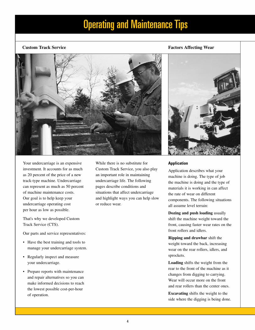
Your undercarriage is an expensive
investment. It accounts for as much
as 20 percent of the price of a new
track-type machine. Undercarriage
can represent as much as 50 percent
of machine maintenance costs.
Our goal is to help keep your
undercarriage operating cost
per hour as low as possible.
That's why we developed Custom
Track Service (CTS).
Our parts and service representatives:
• Have the best training and tools to
manage your undercarriage system.
• Regularly inspect and measure
your undercarriage.
• Prepare reports with maintenance
and repair alternatives so you can
make informed decisions to reach
the lowest possible cost-per-hour
of operation.
While there is no substitute for
Custom Track Service, you also play
an important role in maintaining
undercarriage life. The following
pages describe conditions and
situations that affect undercarriage
and highlight ways you can help slow
or reduce wear.
Application
Application describes what your
machine is doing. The type of job
the machine is doing and the type of
materials it is working in can affect
the rate of wear on different
components. The following situations
all assume level terrain:
Dozing and push loading usually
shift the machine weight toward the
front, causing faster wear rates on the
front rollers and idlers.
Ripping and drawbar shift the
weight toward the back, increasing
wear on the rear rollers, idlers, and
sprockets.
Loading shifts the weight from the
rear to the front of the machine as it
changes from digging to carrying.
Wear will occur more on the front
and rear rollers than the center ones.
Excavating shifts the weight to the
side where the digging is being done.
4
Custom Track Service Factors Affecting Wear

5
Packing
During operation, materials can stick to and pack between matingcomponents such as rollers, links,sprocket teeth, and bushings. Packingprevents parts from engagingcorrectly. This can cause higher loadsand increased wear rates. Packing isinevitable in many applications;however, there are things you can do to reduce the effects of packing.• Use center punched shoes in certain
situations to help relieve extrudablematerials such as wet sand, clay, or snow.
• Clean out your undercarriage as often as possible. Garbage, twigs, stones, and demolition debris cannot be extruded through the center punched shoes.
• Use roller guards only when necessary because they may trap debris and increase the effects of packing. They are designed primarily for use in high-impact underfoot conditions.
Terrain
Most of the time you can’t control theterrain you are working in. However,it is important to understand howcontours and slopes affectundercarriage wear.
Working uphill shifts the weight andload balance to the rear, causinghigher wear on rear rollers andincreasing forward drive side sprocketand bushing wear.
Working downhill shifts weight andload balance forward causing arelatively higher wear rate on fronttrack rollers and idlers.
Working on a side hill shifts theweight and load balance to thedownhill side of the machine. Thisincreases the wear rate on thecomponents and parts on the sides that are on the upper side of the hill.
Working on a crown shifts the loadto the inboard components, increasingwear on inner links, inner roller, idlertreads, and grouser ends.
Working in a depression shifts theload to the outboard components,increasing wear on outer links, outerroller, idler treads, and grouser ends.

Operating and Maintenance Tips
6
Factors Affecting Wear
One of the best ways to protect yourmachine against unnecessary wear isto make sure it is used properly. Allof the following cause additionalwear on the components of yourundercarriage:
• Slipping the track reduces production and increases wear on all undercarriage components, especially on grouser bars.
• Avoid unnecessary reverse operationNon-productive reverse operation
compounds bushing and sprocket wear. If the machine must be
taxied from one location to another, reverse operation will cause more bushing wear regardless of speed.
• Operating the machine at a non- productive high speed may cause link, tractor roller, and idler tread wear. Wear increases proportionally to speed.
• Always turning the machine in one direction may cause link siderail/track roller flange and idler flange wear. Wear increases on one side of the machine because of the greater horsepower and distance traveled.
Always use the narrowest shoe possible
Control the operation of your machine
Use narrow shoes which still provide adequate flotation for yourapplication. Using wider shoes thanrequired by your application can lead to:
• Increased bushing and sprocket wearTurning resistance, loads, and weight increase with wider shoes, especially in rough underfoot conditions. This added stress causes faster wear rates for bushings and sprockets.
• Increased link, track roller, idler tread, and flange wearUsing shoes that are too wide increases the interference between these surfaces, causing them to wear faster.
• Loosening of pins, bushings, and shoe hardwareLeverage forces increase with wider shoes. In high impact or
especially rough terrain, greater leverage forces may lead to premature loosening of bolted and pressed-fit components.
• Reduction of track joint lifeBending forces are exaggerated when using wide shoes in high impact applications, causing pressed track joints to “open up.” This may lead to loss of lubricant, internal wear, and replacement or reconditioning of track joints sooner than expected.
• Shoe breakageSevere turning resistance in extreme conditions and bending forces may cause wide shoes to break.
Your parts and service representativecan help determine the best shoewidth for your underfoot conditions.

7
Be sure your track is always properly adjusted
Every application affectsundercarriage wear differently andrequires proper track adjustment.Adjust your track in the underfootconditions in which your machine isworking. For example, if track that iscorrectly adjusted for a non-packingapplication is put into a packingsituation, packing materials willincrease track tension, making thetrack adjustment too tight. Addedtrack tension increases both the load and the wear on all matingcomponents of your undercarriage.
Improperly adjusted track can resultin problems and wear on othercomponents such as:
• Bushing and sprocket wearTight track increases loads which advances wear. Wear occurs as the bushing rotates and/or slides in the sprocket.
• Link, track roller, and idler wearTo a lesser extent, tight track increases loads between the links, rollers, and idlers. This particularlyaccelerates wear on the idlers.
For information on how to adjustyour track, see Track AdjustmentProcedures.
❏ 1. Call your parts and service representative for expert advice and service.
❏ 2. Adjust the track for correct tension. Always adjust track in its working environment. Correct track adjustment is critical.
❏ 3. Tighten the track hardware correctly, using Caterpillar torque-turn method.
❏ 4. Make daily visual inspections of the equipment. Check for loose bolts, leaking seals, and abnormal wear.
❏ 5. Keep the undercarriage clean of mud and debris so rollers can turn properly.
Operating Checklist
❏ 1. Always use the narrowest shoe possiblewhich still allows adequate flotation.
❏ 2. Minimize high operating speeds in non-productive situations, especially in reverse.
❏ 3. Alternate turning direction since turning only in one direction wears out one side of the machine faster than the other.
❏ 4. Rotate the track from side to side if you or your operators tend to work on one side of the machine more than the other.
❏ 5. Do not spin the tracks since it reducesproduction while increasing wear on allundercarriage components, especially ongrouser bars.
Maintenance Checklist

1
2
3
4
A
B
BA
Track Adjustment Procedures
8
Incorrectly adjusted track can cost you money both in acceleratedundercarriage wear and downtime. If the track is too tight, damaging non-productive loads are placed on the undercarriage and its manualcomponents.
Tight track accelerates track wear and reduces tractor drawbarhorsepower. Adjustment procedurestake only a few minutes and requireonly one person.
When adjusting your track on anyCaterpillar machine:
1. Always adjust the track in the working area.
2. Do not try to squeeze any packingmaterial from in between the track.
3. Never loosen the relief valve more than one turn. Grease and oil are under extreme pressure and canpenetrate the body, causing seriousinjury.
Elevated Sprocket Tractors
1. Move the tractor forward and let itcoast to a stop without applying thebrakes. Make sure slack is betweenthe sprocket and front idler. Then parkthe machine and turn off the engine.
Place a tight line over the grouser tipsfrom the sprocket to the front idler.
2. For machines without carrier rollers,measure the distance “A” from theline to the grouser tip at the lowestpoint of sag. Refer to Chart 1 (page 9)to determine the correct sag for eachmodel.
For machines with carrier rollers,measure the distance from the line to the grouser tips in two places: at thelowest point of sag between the frontidler and carrier roller “A” andbetween the carrier roller and sprocket “B.” Then average the two measurements.
Refer to Chart 2 to determine thecorrect sag for your model.
3. If your track requires adjustment,locate the hydraulic fill and reliefvalve in the rear roller frame, andremove the inspection cover.
Using a manual grease gun, addgrease at the adjustment mechanism totighten the track. To loosen the track,open the relief valve and allow greaseto escape. Then close the relief valve.
4. Operate the machine in forward andreverse, then re-measure track tension.
To avoid damage to internal rollerframe components, do not allow thelength of the exposed tube “B” toexceed the dimensions listed in Chart 3.

9
Chart 2
Proper Track Sag Machines with carrier rollers
Inches Millimeters
Model Min Target Max Min Target Max
D11R, D11N, D10 2.6 3.0 3.4 65 75 85D10T, D10R, D10N, D9L, 589 2.4 2.8 3.2 60 70 80D9T, D9R, D9N 2.2 2.6 3.0 55 65 75D8T, D8R, D8N, D8L, 578, 583T/R 2.2 2.6 3.0 55 65 75D7R, D7H, 572R 2.2 2.6 3.0 55 65 75D6R, D6H, 527 1.8 2.2 2.6 45 55 65D6N, D6M, D5H, 517 1.8 2.2 2.6 45 55 65D5N, D5M, D4H, 561H, 561M 1.0 1.4 1.8 25 35 45
Chart 3
Track Roller Frame Extension SpecificationsMachines with and without carrier rollers
Model (Serial Number Range) Inches Millimeters
D11R (AAF) (7PZ) (9TR00202-UP) (9XR00154-UP) 7.8 198D11R, D11N 7.0 178D10T (RJG), D10R (AKT) (3KR01331-UP), D10 7.3 186D10N (2YD1-515) 5.8 148D10R (3KR1-1330), D10N (2YD516-UP) 6.8 173D9T (RJS), D9R (ACL) (ABK) (8BL1422-UP) (7TL1212-UP) 7.0 178D9R (8BL1-1421) (7TL1-1211), D9N 5.9 150D9L, D8L, 589 6.5 165D8R (7XM1-5093), D8N (9TC) (5TJ) 5.6 142D8T, D8R, 583T/R (7XM5094-UP) (6YZ) (KPZ) 6.0 152D8N, 578 (9TC) (5TC) 5.6 142D7R - STD, XR 5.4 136D7R - LGP, 572R 5.4 136.5D7H - STD, XR 5.0 126D7H - LGP 5.0 127D6R - STD (2YN1-544) (3ZN1-763) 6.2 156.8D6R - STD (2YN545 & UP)(3ZN764 & UP) (AFM) (AEM) 5.8 147.5D6R - XR (6JN1-415) (7KN1-450) 6.2 156.8D6R - XR (6JN416 & UP) (7KN451 & UP) 5.8 147.5D6R - LGP (8LN1-528) (9PN1-1578) 6.0 151.8D6R - LGP (8LN529 & UP)(9PN1579 & UP) (ACJ) (ADE) 5.6 142.5D6R - XL (4MN1-503) (5LN1-2765) 6.0 153.5D6R - XL (4MN504 & UP) (5LN2766 & UP) 5.7 144.2D6R - XW 5.7 144.2D6H - STD, XR 6.4 161.8D6H - LGP, 527 6.2 156.8D6H - XL 6.0 153.5D6M/N - XL 4.0 102.4D6M/N - LGP 4.3 108.2D5M/N - XL 3.6 91.7D5M/N - LGP 3.5 88.5D5H, 517 4.4 112D4H, 561H/M 3.9 100
Max. Length ofExposed Tube
Chart 1
Proper Track Sag Machines without carrier rollers
Inches Millimeters
Model Min Target Max Min Target Max
D11R, D11N, D10 6.1 6.5 6.9 155 165 175D10T, D10R, D10N, D9L, 589 5.7 6.1 6.5 145 155 165D9T, D9R, D9N 4.7 5.1 5.5 120 130 140D8T, D8R, D8N, 578, 583T/R 4.1 4.5 4.9 105 115 125D8L 5.1 5.5 5.9 130 140 150D7R, D7H, 572R 4.1 4.5 4.9 105 115 125D6R, D6H, 527 4.1 4.5 4.9 105 115 125D5H, D4H, 517, 561H, 561M 3.5 3.9 4.3 90 100 110

6 & 7
1
3
4
5
8
A
2
B
Track Adjustment Procedures
10
Low Sprocket Tractors and Loaders
1. Move the machine forward and let it coast to a stop without applying thebrakes. Then park the machine and turn off the engine.
Place a tight line over the grouser tipsfrom the sprocket to the front idler.Track sag should be about 2 inches or 50 millimeters. If your track requires adjustment, complete the following steps.
2. Connect the grease gun to the fittingat the track adjustment mechanism “A” located under the inspection plate.“B” is the front idler bearing assembly.
3. Add grease to extend the hydraulictrack adjuster until the idler is atmaximum forward position. The relief valve should remain closed.
After adding grease, the track should be almost straight between the frontcarrier roller and idler.
4. On machines with one carrier rollerper side, place a mark on the trackroller frame .4 inch or 10 millimetersbehind the rear edge of the front idlerbearing assembly “B.”
On machines with more than onecarrier roller per side, mark the trackroller frame .5 inch or 13 millimetersbehind the rear edge of the assembly.
5. Open the hydraulic relief valve.
6. Place a track pin or drawbar pinbetween the sprocket teeth near the link assembly.
7. Travel in reverse until the idler backs up at least .5 inch or 13millimeters. Move the machine forward until the pin is free of the track, then remove the pin.
8. Close the hydraulic relief valve.
Using the grease gun, extend thehydraulic track adjuster until the rear edge of the idler bearing assembly aligns with the mark on the roller frame.
The resulting sag should be about 2 inches or 50 millimeters. Operate the machine in forward and reverse,then reinspect track adjustment.

11
Hydrostatic Loaders
1. Move the machine forward and letit slowly come to a stop. Then parkthe machine and turn off the engine.
Place a tight line over the grousertips from the sprocket to the front idler.
Measure the distance from the line to the grouser tips at the lowest pointof sag. Proper track tension is about2 inches or 50 millimeters.
2. If the track requires adjustment,remove the cover for the adjustingmechanism.
Connect the grease gun to the fitting.Add grease to move the idler forwarduntil the track is tight.
3. Using a straight edge, make a mark on the rod even with the recoilhousing “A.”
4. Place a second mark on the rod .4 inch or 10 millimeter from the first mark, in the direction of theidler. On the 973, place the mark onthe rod .5 inch or 13 millimeters inthe direction of the idler.
5. Open the relief valve and let theidler drift back until the second markis behind the recoil housing. Thenclose the relief valve.
Using a grease gun, move the idlerforward until the second mark iseven with the recoil housing. Theresulting sag should be about 2 inches or 50 millimeters.
Operate the machine in forward andreverse, then reinspect the track.
6. As wear increases on the track linkand rolling components, the distancebetween the piston “B” and recoilhousing “C” will increase. Consult aCaterpillar Service Manual or contactus when the distance exceeds:
• 2 inches or 50 millimeters on 943and 953 Track Loaders
• 2.36 inches or 60 millimeters on963 and 973 Track Loaders
3
2
1
4
5
6
A
BC

Track Adjustment Procedures
12
Hydraulic Excavators
1. Operate the machine in the directionof the idlers.
2. Stop with one track pin directly overthe front carrier roller. Park themachine and turn off the engine.
3. Place a tight line or straight edge ontop of the grousers between the frontcarrier roller and idler.
Measure the distance from the straightedge to the grouser tip at the lowestpoint of sag, midway between the frontcarrier roller and idler.
Refer to Chart 4 to determine thecorrect sag for each model.
4. If the track is too tight, loosen it by opening the relief valve and allowinggrease to escape.
5. Tighten track by adding grease at thehydraulic fill and relief valve. Travel in forward and reverse to equalize tensionthroughout the track. Then reinspect adjustment.
1
2
3
4
5
Chart 4
Proper Track Sag Inches Millimeters
Model Min Target Max Min Target Max
All 200-Family series excavators 1.0 1.3 1.5 25.0 32.5 40.0All E-Family series excavators 1.6 1.85 2.1 40.0 47.5 55.0All 300-Family series excavators 1.6 1.85 2.1 40.0 47.5 55.05080, 5090B, 5130, 5130B, 5110B 1.6 1.85 2.1 40.0 47.5 55.0

13
Hardware Requirements
Track Roller and Idler Caps
Inadequate clamping of the track rollerand idler caps can result in brokenretaining bolts and damage to theframe or bogie bore.
To install roller and idler hardware:
1. Lubricate the bolt threads with5P3931 Anti-seize Compound.
2. Align the shaft and cap dowel holesto ensure proper bearing lubricationand shaft movement.
3. Snug both bolts evenly prior totorquing.
4. Tighten the bolts to the specifiedtorque shown in the charts below.
5. To ensure correct mounting, theremust be a minimum gap of .13 mm(.005") as shown in the illustration. If there is insufficient clearance,remove cap and grind or machine off sufficient material from the cap to achieve the correct gap.
Sprocket Segment
The principal cause of segmentloosening and subsequent loss and/ordamage to other parts is incorrectsegment hardware installation.
To install segment hardware:
1. Lubricate the bolt threads and thewasher face of the nut with 5P3931Anti-seize Compound.
2. Tighten all nuts on any one segmentto the specified initial torque shown inthe chart. This draws the mating partstogether tightly.
3. Tighten each nut an additional 1/3turn. This stretches the bolt properly for good retention.
Elevated Sprocket - Roller Hardware Torque RequirementsModel Bolt Size Torque
D4H, 943 5/8" 200 ± 20 lb ft (270 ± 25 N·m)
D5N, D5M, D5H, D6N, D6M, 953 M16 200 ± 30 lb ft (270 ± 40 N·m)D6H, 963 3/4" 360 ± 45 lb ft (475 ± 60 N·m)D6R, 963 M20 400 ± 50 lb ft (540 ± 70 N·m)D7R, D7H, D8T, D8R, D8N, D8L, D9T, D9R, D9N 7/8" 550 ± 65 lb ft (750 ± 90 N·m)D9L, D10T, D10R, D10N 1" 850 ± 75 lb ft (1125 ± 100 N·m)D10 1-1/8" 1015 ± 105 lb ft (1350 ± 135N·m)
Elevated Sprocket - Idler Hardware Initial Torque RequirementsModel Bolt Size Torque
D5H, D4H 5/8" 200 ± 30 lb ft (270 ± 40 N·m)D5N, D5M, D6N, D6M M16 200 ± 30 lb ft (270 ± 40 N·m)
D6R M20 430 ± 60 lb ft (570 ± 80 N·m)D6H 3/4" 360 ± 45 lb ft (475 ± 60 N·m)
D7R, D7H 7/8" 550 ± 65 lb ft (750 ± 90 N·m)D9L, D8L 1" 850 ± 75 lb ft (1125 ± 100 N·m)D9T, D9R, D9N, D8T, D8R, D8N 1-1/8" 1185 ± 150 lb ft (1600 ± 200N·m)D10T, D10R, D10N, D10 1-1/4" 1700 ± 220 lb ft (2300 ± 300N·m)D11R 1-3/8" 2220 ± 260 lb ft (3000 ± 350
Low Sprocket - Sprocket Segment Hardware Initial TorqueModel Bolt Size Initial Torque
D4G, D4C, D3G, D3C, 935 1/2" 50 ± 8 lb ft (70 ± 10 N·m) 953C M16 75 ± 15 lb ft (100 ± 20 N·m) D6, D5G, D5C, D5, 973, 963,955, 953B, 943, 939 5/8" 130 ± 30 lb ft (175 ± 40 N·m)D7, 977, 973 3/4" 220 ± 40 lb ft (300 ± 50 N·m)D9, D8, 983 7/8" 250 ± 50 lb ft (340 ± 70 N·m)
Elevated Sprocket - Sprocket Segment Hardware Initial TorqueModel Bolt Size Initial Torque
D6R, D6N, D6M, D5N, D5MD5H, D4H 5/8" 130 ± 30 lb ft (175 ± 40 N·m) D8T, D8R, D8N, D8L, D7R 3/4" 220 ± 40 lb ft (300 ± 50 N·m)D9L 7/8" 650 ± 50 lb ft (870 ± 70 N·m)D9T, D9R, D9N 7/8" 480 ± 50 lb ft (650 ± 70 N·m)D10T, D10R, D10N, D10 1" 650 ± 50 lb ft (870 ± 70 N·m)D11R, D11N 1-1/8" 650 ± 50 lb ft (870 ± 70 N·m)
Hardware Requirements
14
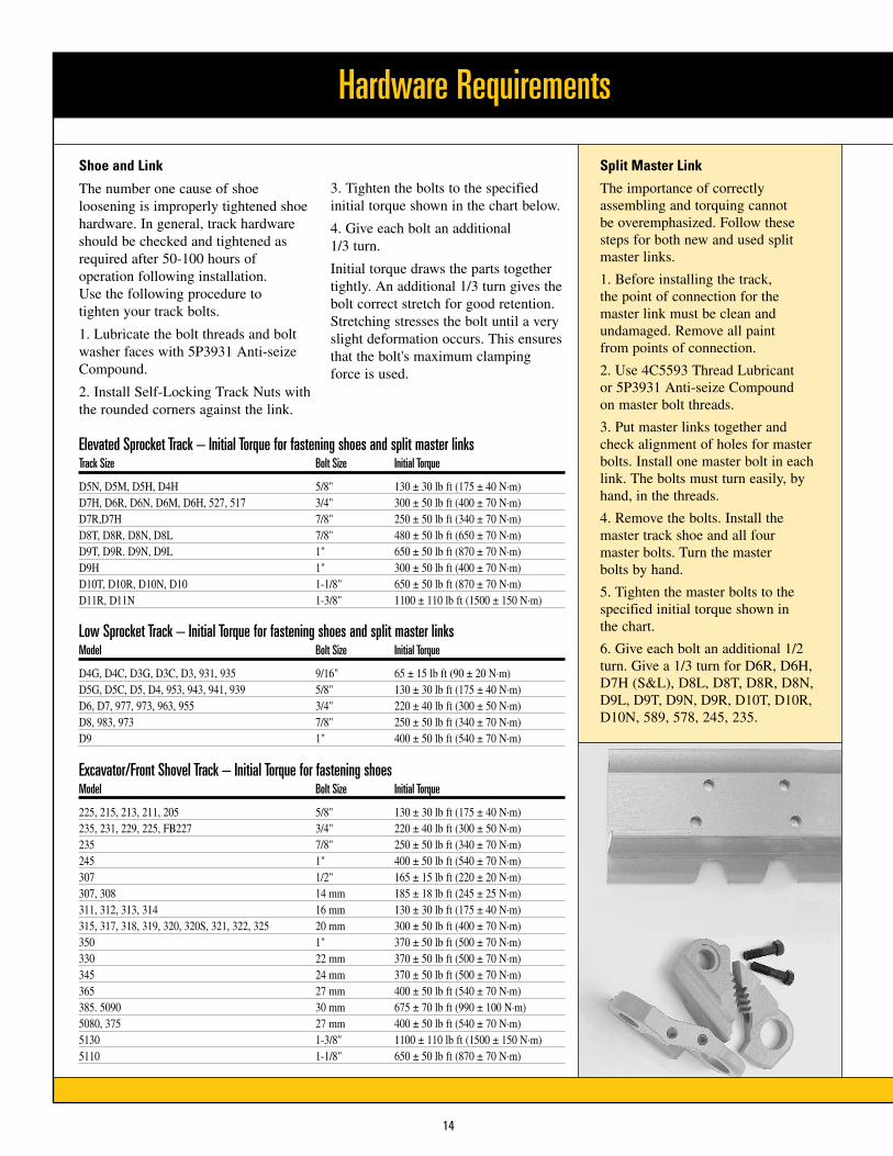
Elevated Sprocket Track – Initial Torque for fastening shoes and split master linksTrack Size Bolt Size Initial Torque
D5N, D5M, D5H, D4H 5/8" 130 ± 30 lb ft (175 ± 40 N·m)D7H, D6R, D6N, D6M, D6H, 527, 517 3/4" 300 ± 50 lb ft (400 ± 70 N·m)D7R,D7H 7/8" 250 ± 50 lb ft (340 ± 70 N·m)D8T, D8R, D8N, D8L 7/8" 480 ± 50 lb ft (650 ± 70 N·m)D9T, D9R. D9N, D9L 1" 650 ± 50 lb ft (870 ± 70 N·m)D9H 1" 300 ± 50 lb ft (400 ± 70 N·m)D10T, D10R, D10N, D10 1-1/8" 650 ± 50 lb ft (870 ± 70 N·m)D11R, D11N 1-3/8" 1100 ± 110 lb ft (1500 ± 150 N·m)
Low Sprocket Track – Initial Torque for fastening shoes and split master linksModel Bolt Size Initial Torque
D4G, D4C, D3G, D3C, D3, 931, 935 9/16" 65 ± 15 lb ft (90 ± 20 N·m)D5G, D5C, D5, D4, 953, 943, 941, 939 5/8" 130 ± 30 lb ft (175 ± 40 N·m)D6, D7, 977, 973, 963, 955 3/4" 220 ± 40 lb ft (300 ± 50 N·m)D8, 983, 973 7/8" 250 ± 50 lb ft (340 ± 70 N·m)D9 1" 400 ± 50 lb ft (540 ± 70 N·m)
Excavator/Front Shovel Track – Initial Torque for fastening shoesModel Bolt Size Initial Torque
225, 215, 213, 211, 205 5/8" 130 ± 30 lb ft (175 ± 40 N·m)235, 231, 229, 225, FB227 3/4" 220 ± 40 lb ft (300 ± 50 N·m)235 7/8" 250 ± 50 lb ft (340 ± 70 N·m)245 1" 400 ± 50 lb ft (540 ± 70 N·m)307 1/2" 165 ± 15 lb ft (220 ± 20 N·m)307, 308 14 mm 185 ± 18 lb ft (245 ± 25 N·m)311, 312, 313, 314 16 mm 130 ± 30 lb ft (175 ± 40 N·m)315, 317, 318, 319, 320, 320S, 321, 322, 325 20 mm 300 ± 50 lb ft (400 ± 70 N·m)350 1" 370 ± 50 lb ft (500 ± 70 N·m)330 22 mm 370 ± 50 lb ft (500 ± 70 N·m)345 24 mm 370 ± 50 lb ft (500 ± 70 N·m)365 27 mm 400 ± 50 lb ft (540 ± 70 N·m)385. 5090 30 mm 675 ± 70 lb ft (990 ± 100 N·m)5080, 375 27 mm 400 ± 50 lb ft (540 ± 70 N·m)5130 1-3/8" 1100 ± 110 lb ft (1500 ± 150 N·m)5110 1-1/8" 650 ± 50 lb ft (870 ± 70 N·m)
Shoe and Link
The number one cause of shoeloosening is improperly tightened shoehardware. In general, track hardwareshould be checked and tightened asrequired after 50-100 hours ofoperation following installation. Use the following procedure to tighten your track bolts.
1. Lubricate the bolt threads and boltwasher faces with 5P3931 Anti-seizeCompound.
2. Install Self-Locking Track Nuts withthe rounded corners against the link.
3. Tighten the bolts to the specifiedinitial torque shown in the chart below.
4. Give each bolt an additional 1/3 turn.
Initial torque draws the parts togethertightly. An additional 1/3 turn gives thebolt correct stretch for good retention.Stretching stresses the bolt until a veryslight deformation occurs. This ensuresthat the bolt's maximum clampingforce is used.
Split Master Link
The importance of correctlyassembling and torquing cannot be overemphasized. Follow thesesteps for both new and used splitmaster links.
1. Before installing the track, the point of connection for themaster link must be clean andundamaged. Remove all paint from points of connection.
2. Use 4C5593 Thread Lubricant or 5P3931 Anti-seize Compound on master bolt threads.
3. Put master links together andcheck alignment of holes for masterbolts. Install one master bolt in eachlink. The bolts must turn easily, byhand, in the threads.
4. Remove the bolts. Install themaster track shoe and all fourmaster bolts. Turn the master bolts by hand.
5. Tighten the master bolts to thespecified initial torque shown in the chart.
6. Give each bolt an additional 1/2turn. Give a 1/3 turn for D6R, D6H,D7H (S&L), D8L, D8T, D8R, D8N,D9L, D9T, D9N, D9R, D10T, D10R,D10N, 589, 578, 245, 235.

15
Notes
PEGP5027-04 www.cat.com Printed in USA © 2006 Caterpillar All Rights Reserved
Expect More from the Experts
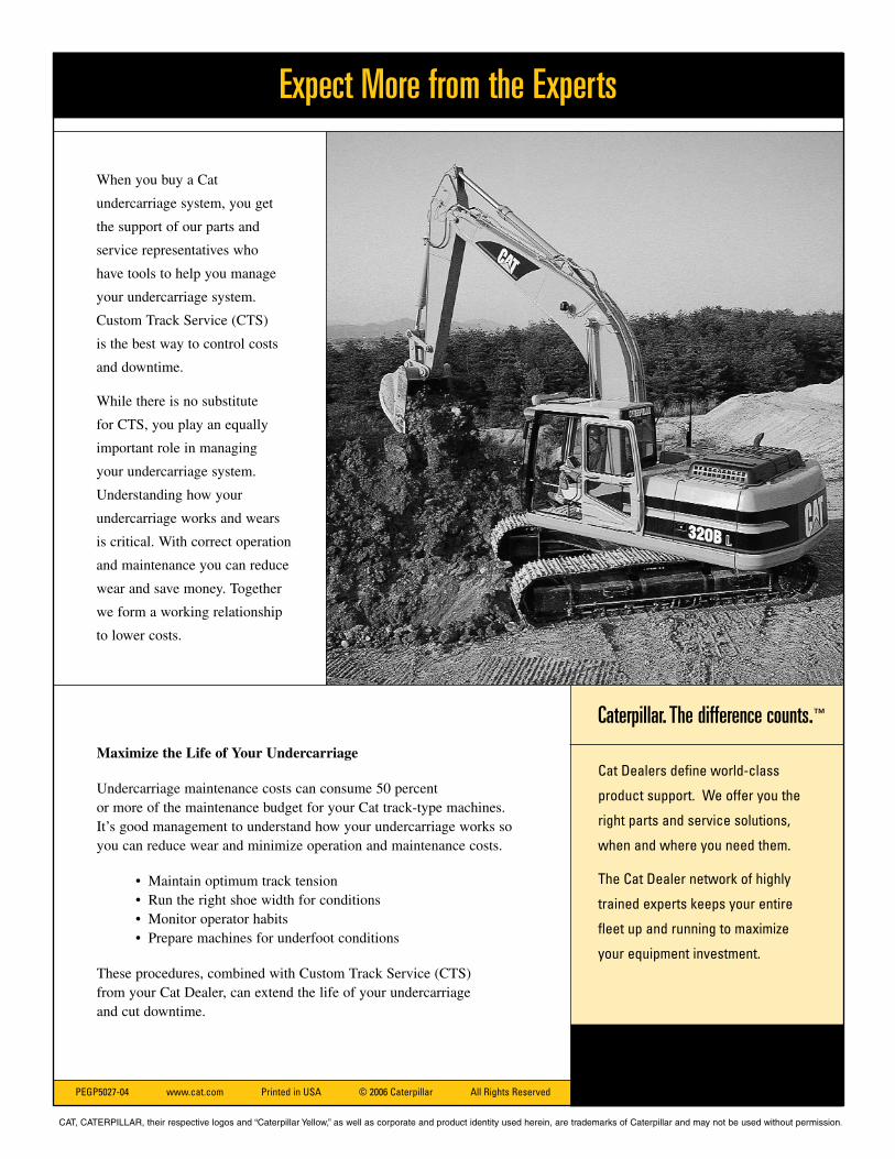
Maximize the Life of Your Undercarriage
Undercarriage maintenance costs can consume 50 percent or more of the maintenance budget for your Cat track-type machines.It’s good management to understand how your undercarriage works soyou can reduce wear and minimize operation and maintenance costs.
• Maintain optimum track tension• Run the right shoe width for conditions• Monitor operator habits• Prepare machines for underfoot conditions
These procedures, combined with Custom Track Service (CTS) from your Cat Dealer, can extend the life of your undercarriage and cut downtime.
Caterpillar. The difference counts.™
Cat Dealers define world-class
product support. We offer you the
right parts and service solutions,
when and where you need them.
The Cat Dealer network of highly
trained experts keeps your entire
fleet up and running to maximize
your equipment investment.
When you buy a Cat
undercarriage system, you get
the support of our parts and
service representatives who
have tools to help you manage
your undercarriage system.
Custom Track Service (CTS)
is the best way to control costs
and downtime.
While there is no substitute
for CTS, you play an equally
important role in managing
your undercarriage system.
Understanding how your
undercarriage works and wears
is critical. With correct operation
and maintenance you can reduce
wear and save money. Together
we form a working relationship
to lower costs.
CAT, CATERPILLAR, their respective logos and “Caterpillar Yellow,” as well as corporate and product identity used herein, are trademarks of Caterpillar and may not be used without permission.