Embed Size (px)
DESCRIPTION
h
Citation preview
beams, a relation of b and d of the members, to ensure lateral stability. Theyare given below:
(A) For the deflection requirements
Different basic values of span to effective depth ratios for three differentsupport conditions are prescribed for spans up to 10 m, which should be modifiedunder any or all of the four different situations: (i) for spans above 10 m, (ii)depending on the amount and the stress of tension steel reinforcement, (iii)depending on the amount of compression reinforcement, and (iv) for flangedbeams. These are furnished in Table 7.1.
(B) For lateral stabil ity
The lateral stability of beams depends upon the slenderness ratio and thesupport conditions. Accordingly cl. 23.3 of IS code stipulates the following:
(i) For simply supported and continuous beams, the clear distancebetween the lateral restraints shall not exceed the lesser of 60b or 250b2/d,where d is the effective depth and b is the breadth of the compression facemidway between the lateral restraints.
(ii) For cantilever beams, the clear distance from the free end of thecantilever to the lateral restraint shall not exceed the lesser of 25b or 100b2/d.
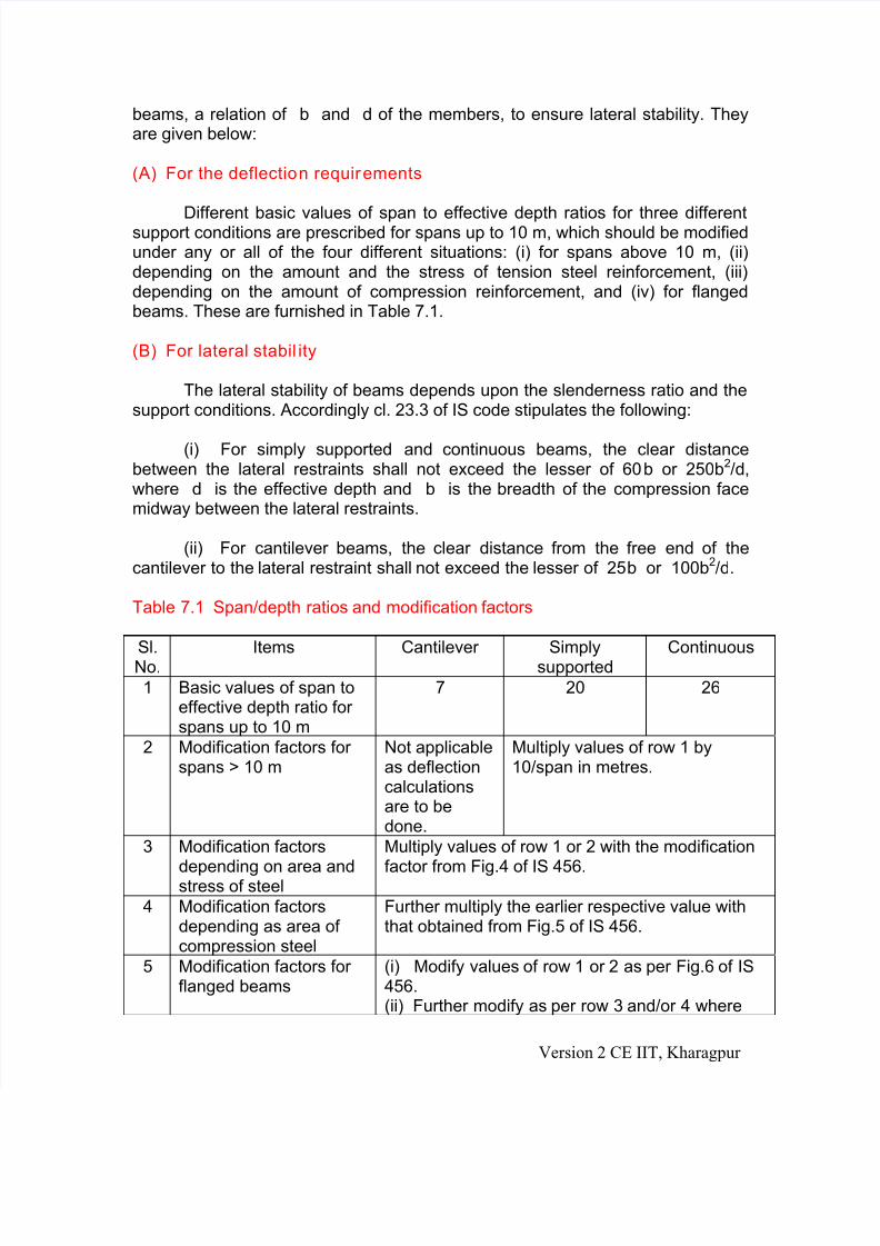
Table 7.1 Span/depth ratios and modification factors
Sl.No.
Items Cantilever Simplysupported
Continuous
1 Basic values of span toeffective depth ratio forspans up to 10 m
7 20 26
2 Modification factors forspans > 10 m
Not applicableas deflectioncalculationsare to bedone.
Multiply values of row 1 by10/span in metres.
3 Modification factorsdepending on area andstress of steel
Multiply values of row 1 or 2 with the modificationfactor from Fig.4 of IS 456.
4 Modification factorsdepending as area ofcompression steel
Further multiply the earlier respective value withthat obtained from Fig.5 of IS 456.
5 Modification factors forflanged beams
(i) Modify values of row 1 or 2 as per Fig.6 of IS456.(ii) Further modify as per row 3 and/or 4 where
Version 2 CE IIT, Kharagpur