Embed Size (px)
Citation preview

3.1 Air Conditioning (A/C) Contents
3.1 Model 129 up to M.Y. 1997
Diagnosis PageDiagnostic Trouble Code (DTC) Memory . . . . . . . . . . . . . . . . 11/1Complaint Related Diagnostic Chart . . . . . . . . . . . . . . . . . . . 12/1
Electrical Test ProgramComponent Locations . . . . . . . . . . . . . . . . . . . . . . . . . . . . . 21/1Preparation for Test . . . . . . . . . . . . . . . . . . . . . . . . . . . . . . 22/1Test . . . . . . . . . . . . . . . . . . . . . . . . . . . . . . . . . . . . . . . . . 23/1
Electrical Test Program (Compressor Shut-Off)Component Locations . . . . . . . . . . . . . . . . . . . . . . . . . . . . . 24/1Preparation for Test . . . . . . . . . . . . . . . . . . . . . . . . . . . . . . 25/1Test . . . . . . . . . . . . . . . . . . . . . . . . . . . . . . . . . . . . . . . . . 26/1
b Diagnostic Manual • Climate Control • 08/94 3.1 A/C C/1

3.1 Air Conditioning (A/C) Model 129
Diagnosis – Diagnostic Trouble Code (DTC) Memory
P83-2086-35B
Testing via temperature window display
This test is divided into the following test modes:A. Continuous display, instantaneous display of actual temperature sensor
readings, temperature selector wheel setting, vehicle speed, systemvoltage and soft top position.
B. Display of permanent and intermittent diagnostic trouble codes (DTC)stored in memory.
C. Testing the temperature sensors, potentiometer and feedbackpotentiometer.
� � � � � � � � � � � � � � � � � � � � � � � � � � � � � � � � � � � � � � � � � � � � � � � � � � � � � � � � � �
� � � � � � � � � � � � � � � � � � � � � � � � � � � � � � � � � � � � � � � � � � � � � � � � � � � � � � � � � �
� � � � � � � � � � � � � � � � � � � � � � � � � � � � � � � � � � � � � � � � � � � � � � � � � � � � � � � � � �
� � � � � � � � � � � � � � � � � � � � � � � � � � � � � � � � � � � � � � � � � � � � � � � � � � � � � � � � � �
� � � � � � � � � � � � � � � � � � � � � � � � � � � � � � � � � � � � � � � � � � � � � � � � � � � � � � � � � �
Figure 1
Note:If no DTC can be found when testing via the temperature window display andwith the socket box, for example the footwell vacuum flap does not open, it ispossible there is a leak in the vacuum system. Check vacuum system, seeSMS job no. 83-520.
b Diagnostic Manual • Climate Control • 08/94 3.1 A/C 11/1

3.1 Air Conditioning (A/C) Model 129
Diagnosis – Diagnostic Trouble Code (DTC) Memory
P83-2086-35B
Test mode A.
Note: To select this test mode
Ignition ON. Press h, and within 1 second press blower speed button 4.The temperature window (arrow) will alternately display the test step number“02” with the in-car temperature (in oC) or “OP E” if there is an open circuitor “CL O” if there is a short circuit.Press f to go to next higher test step, andPress c to go to previous test step.To exit this test mode, turn ignition OFF and wait 5 seconds
� � � � � � � � � � � � � � � � � � � � � � � � � � � � � � � � � � � � � � � � � � � � � � � � � � � � � � � � � �
� � � � � � � � � � � � � � � � � � � � � � � � � � � � � � � � � � � � � � � � � � � � � � � � � � � � � � � � � �
� � � � � � � � � � � � � � � � � � � � � � � � � � � � � � � � � � � � � � � � � � � � � � � � � � � � � � � � � �
� � � � � � � � � � � � � � � � � � � � � � � � � � � � � � � � � � � � � � � � � � � � � � � � � � � � � � � � � �
� � � � � � � � � � � � � � � � � � � � � � � � � � � � � � � � � � � � � � � � � � � � � � � � � � � � � � � � � �
Figure 2
b Diagnostic Manual • Climate Control • 08/94 3.1 A/C 11/2
3.1 Air Conditioning (A/C) Model 129
Diagnosis – Diagnostic Trouble Code (DTC) Memory
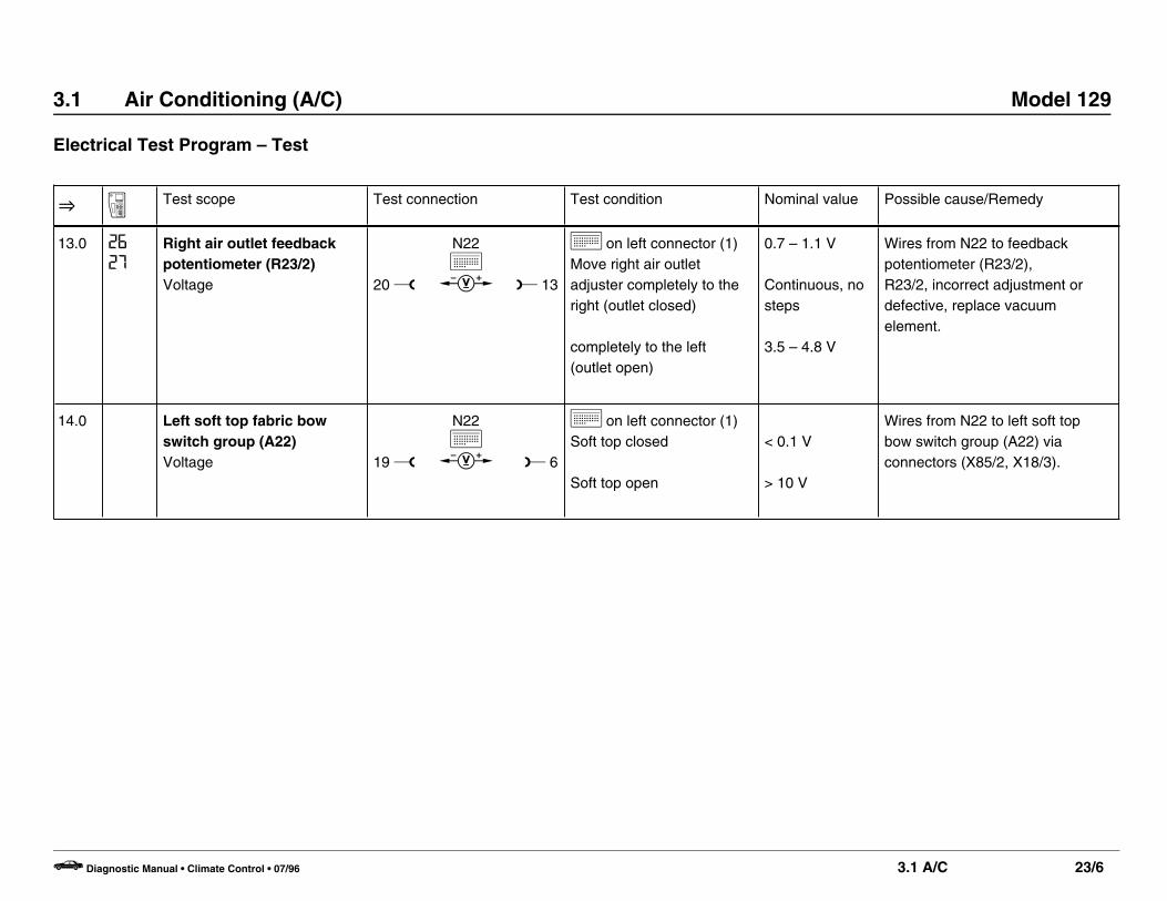
Test step display Possible Cause Test Step/Remedy 1)
02 In – car temperature sensor 23 O 1.0
04 Outside temperature sensor 23 O 2.0
06 Evaporator temperature sensor 23 O 3.0
08 Heater core temperature sensor 23 O 4.0
I2 ECT sensor 23 O 5.0
I4 Temperature selector wheel setting (oC) A/C pushbutton control module
I8 Vehicle speed (km/h) DM, Body and Accessories, Vol. 2 – 11.2
20 Soft top open u, soft top closed o 23 O 14.0
22 System voltage 23 O 16.0 – 17.0
83 OFF/ON (not used) –
84 2) Blower voltage 050 (0.5 V) – 600 (6.0 V) 23 O 22.0
1) Observe Preparation for Test, see 22.2) Starting approximately 11/91.
b Diagnostic Manual • Climate Control • 08/94 3.1 A/C 11/3

3.1 Air Conditioning (A/C) Model 129
Diagnosis – Diagnostic Trouble Code (DTC) Memory
P83-2086-35B
Test modesB. Display of permanent and intermittent DTC’s stored in memory.C. Testing the temperature sensors, potentiometer and feedback
potentiometer
Notes for Diagnosis• The A/C pushbutton control module (N22) has DTC memory and the
capability to display the codes via the temperature display window (arrow)on the A/C pushbutton control panel. The stored DTC’s will remain inmemory even with the vehicle battery disconnected.
• The DTC readout displays permanent as well as intermittent fault codes.The number “0I” indicates that there are no stored fault codes in thesystems memory. All other numbers refer to a specific fault code source.
• The display window will show in sequence the actual temperatures of theindividual sensors and the voltages at the potentiometers and feedbackpotentiometers. Thereby allowing the tolerance range of the temperaturesensors and the adjustment of the feedback potentiometers to bechecked.
� � � � � � � � � � � � � � � � � � � � � � � � � � � � � � � � � � � � � � � � � � � � � � � � � � � � � � � � � �
� � � � � � � � � � � � � � � � � � � � � � � � � � � � � � � � � � � � � � � � � � � � � � � � � � � � � � � � � �
� � � � � � � � � � � � � � � � � � � � � � � � � � � � � � � � � � � � � � � � � � � � � � � � � � � � � � � � � �
� � � � � � � � � � � � � � � � � � � � � � � � � � � � � � � � � � � � � � � � � � � � � � � � � � � � � � � � � �
� � � � � � � � � � � � � � � � � � � � � � � � � � � � � � � � � � � � � � � � � � � � � � � � � � � � � � � � � �
Figure 3
b Diagnostic Manual • Climate Control • 08/94 3.1 A/C 11/4

3.1 Air Conditioning (A/C) Model 129
Diagnosis – Diagnostic Trouble Code (DTC) Memory
Test preparations for test modes B. and C.• Turn temperature selector wheel to white field.
• Turn ignition “ON” and within 10 seconds press f, k and hsimultaneously for 2 to 4 seconds.
• The display will show permanent DTC’s stored in memory. After eachDTC is displayed and recorded, press k again until the displayreads “End”.
• Press k once again. Now the stored intermittent DTC’s will bedisplayed. The symbol will appear after each DTC to indicate anintermittent fault. After each DTC is displayed and recorded, pressk again unttil the dissplay reads “End”.
• Press k once again. The display will alternately blink the number“02” and the in – car temperature in oC. Press k until alltemperature sensor display numbers from 02 – I2 are shown (seesection C).Press k once again and the display will alternately blink the number“I6” and the voltage of the potentiometer for the center air outlet flapdependent upon the setting (open or closed). The voltage, forexample, for 3.5 V is displayed as “35u”. Press k until allpotentiometer and feedback potentiometer display numbers from I6 – 26 are shown. Press k until the display reads “End” andthe symbol blinks.
• Turn ignition OFF and repair recorded DTC’s.
Note:The DTC’s can be redisplayed as often as desired. To do so, turn ignitionOFF and ON and within 10 seconds press f, k and hsimultaneously for 2 to 4 seconds and then press only k. The lightdiode inside k will blink once per second during the impulse readout.
Erasing DTC’s• Turn ignition ON and within 10 seconds press k, h and u
simultaneously for 2 to 4 seconds until “– – –” appears on thedisplay.
Verification• Repeat readout of DTC’s. The number “0I” (no fault) must appear in
the display window.
Electrical Wiring Diagrams:See “Electrical Troubleshooting Manual”, Model 129
b Diagnostic Manual • Climate Control • 08/94 3.1 A/C 11/5

3.1 Air Conditioning (A/C) Model 129
Diagnosis – Diagnostic Trouble Code (DTC) Memory
B. DTC readout with permanent and intermittent faults
Diagnostic TroubleCode (DTC)
Possible Cause Test Step/Remedy 1)
0I No stored DTC’s in system memory –
02 In – car temperature sensor (B10/4), short circuit 23 O 1.0
03 In – car temperature sensor (B10/4), open circuit 23 O 1.0
04 Outside temperature sensor (B10/5), short circuit 23 O 2.0
05 Outside temperature sensor (B10/5), open circuit 23 O 2.0
06 Evaporator temperature sensor (B10/6), short circuit 23 O 3.0
07 Evaporator temperature sensor (B10/6), open circuit 23 O 3.0
08 Heater core temperature sensor (B10/1), short circuit 23 O 4.0
09 Heater core temperature sensor (B10/1), open circuit 23 O 4.0
I2 ECT sensor (B10/8), short circuit 23 O 5.0
I3 ECT sensor (B10/8), open circuit 23 O 5.0
I6 Center air outlet adjuster (N18/2r2), short circuit 23 O 7.0
1) Observe Preparation for Test, see 22.
b Diagnostic Manual • Climate Control • 08/94 3.1 A/C 11/6

3.1 Air Conditioning (A/C) Model 129
Diagnosis – Diagnostic Trouble Code (DTC) Memory
Diagnostic TroubleCode (DTC)
Possible Cause Test Step/Remedy 1)
I7 Center air outlet adjuster (N18/2r2), open circuit 23 O 7.0
I8 Center air outlet feedback potentiometer (R23/3), short circuit 23 O 12.0
I9 Center air outlet feedback potentiometer (R23/3), open circuit 23 O 12.0
20 Left air outlet adjuster (N18/2r1), short circuit 23 O 6.0
2I Left air outlet adjuster (N18/2r1), open circuit 23 O 6.0
22 Left air outlet feedback potentiometer (R23/1), short circuit 23 O 11.0
23 Left air outlet feedback potentiometer (R23/1), open circuit 23 O 11.0
24 Right air outlet adjuster (N18/2r3), short circuit 23 O 8.0
25 Right air outlet adjuster (N18/2r3), open circuit 23 O 8.0
26 Right air outlet feedback potentiometer (R23/2), short circuit 23 O 13.0
27 Right air outlet feedback potentiometer (R23/2), open circuit 23 O 13.0
30 Auxiliary coolant pump (M13), short circuit 23 O 20.0
1) Observe Preparation for Test, see 22.
b Diagnostic Manual • Climate Control • 08/94 3.1 A/C 11/7

3.1 Air Conditioning (A/C) Model 129
Diagnosis – Diagnostic Trouble Code (DTC) Memory
Diagnostic TroubleCode (DTC)
Possible Cause Test Step/Remedy 1)
3I Automatic A/C monovalve (Y19), short circuit 23 O 19.0
33 A/C compressor signal, short circuit 23 O 25.0
34 Auxiliary fan signal, 2nd stage, short circuit 23 O 24.0
35 Auxiliary fan signal, 1st stage, short circuit 23 O 23.0
36 Not used –
50 Switchover valve block (Y11), short circuit 23 O 21.0
70 Auxiliary coolant pump (M13), open circuit 23 O 20.0
7I Automatic A/C monovalve (Y19), open circuit 23 O 15.0
73 A/C compressor signal, open circuit 23 O 25.0
74 Auxiliary fan signal, 2nd stage, open circuit 23 O 24.0
75 Auxiliary fan signal, 1st stage, open circuit 23 O 23.0
1) Observe Preparation for Test, see 22.
b Diagnostic Manual • Climate Control • 08/94 3.1 A/C 11/8

3.1 Air Conditioning (A/C) Model 129
Diagnosis – Diagnostic Trouble Code (DTC) Memory
C. Readout of momentary sensor temperatures as well as potentiometer and feedback potentiometer voltages.
Test step Test scope Test connection Nominal value Test step/Remedy
02 In – car temperature sensor Press k Indicated value may deviate by nomore than ± 1 oC
23 O 1.0
04 Outside temperature sensor Press k Indicated value may deviate by nomore than ± 3 oC
23 O 2.0
06 Evaporator temperature sensor Press k Indicated value may deviate by nomore than ± 3 oC
23 O 3.0
08 Heater core temperature sensor Press k Indicated value may deviate by nomore than ± 3 oC
23 O 4.0
I2 ECT sensor Press k Indicated value may deviate by nomore than ± 3 oC
23 O 6.0
b Diagnostic Manual • Climate Control • 08/94 3.1 A/C 11/9

3.1 Air Conditioning (A/C) Model 129
Diagnosis – Diagnostic Trouble Code (DTC) Memory
Test step Test scope Test connection Display Nominal value Test step/Remedy
I6 Center air outlet adjuster Move center air outlet adjustercompletely to the right (outletclosed)
Move center air outlet adjustercompletely to the left (outletopen)
06 – 09 U 0.6 – 0.9 V
39 – 45 U 3.9 – 4.5 V
23 O 8.0
I8 Center air outlet feedback potentiometer Move center air outlet adjustercompletely to the right (outletclosed)
Move center air outlet adjustercompletely to the left (outletopen)
07 – I I U 0.7 – 1.1 V
35 – 48 U 3.5 – 4.8 V
23 O 13.0
20 Left air outlet adjuster Move left air outlet adjustercompletely to the right (outletclosed)
Move left air outlet adjustercompletely to the left (outletopen)
06 – 09 U 0.6 – 0.9 V
39 – 45 U 3.9 – 4.5 V
23 O 7.0
b Diagnostic Manual • Climate Control • 08/94 3.1 A/C 11/10

3.1 Air Conditioning (A/C) Model 129
Diagnosis – Diagnostic Trouble Code (DTC) Memory
Test step Test scope Test connection Nominal value Possible cause/Remedy
22 Left air outlet feedback potentiometer Move left air outlet adjustercompletely to the right (outletclosed)
Move left air outlet adjustercompletely to the left (outletopen)
07 – I I U 0.7 – 1.1 V
35 – 48 U 3.5 – 4.8 V
23 O 12.0
24 Right air outlet adjuster Move right air outlet adjustercompletely to the right (outletclosed)
Move right air outlet adjustercompletely to the left (outletopen)
06 – 09 U 0.6 – 0.9 V
39 – 45 U 3.9 – 4.5 V
23 O 9.0
26 Right air outlet feedback potentiometer Move right air outlet adjustercompletely to the right (outletclosed)
Move right air outlet adjustercompletely to the left (outletopen)
07 – I I U 0.7 – 1.1 V
35 – 48 U 3.5 – 4.8 V
23 O 14.0
b Diagnostic Manual • Climate Control • 08/94 3.1 A/C 11/11

3.1 Air Conditioning (A/C) Model 129
Diagnosis – Complaint Related Diagnostic Chart
Complaint/Problem Possible cause Test step/Remedy 1)
A/C compressor does not switch on. Insufficient rpm sensor voltage or no TD/TN signal 26 O 1.0 – 5.0
1) Observe Preparation for Test, see 22.
b Diagnostic Manual • Climate Control • 08/94 3.1 A/C 12/1

3.1 Air Conditioning (A/C) Model 129
Electrical Test Program – Component Locations
P83-0042-57A
Electrical Components in PassengerCompartment
Figure 1B10/2 Left heater core temperature sensorB10/4 In – car temperature sensor (with aspirator blower in E15)B10/6 Evaporator temperature sensorM9 In – car temperature sensor aspirator blowerN18/2 Center and side air outlet flap control moduleN22 A/C pushbutton control module (Automatic A/C)X85/2 Heater/interior connector (12–pole)Y11 Switchover valve block (15 connections, multiplex)46 Vacuum actuator with left air outlet feedback potentiometer
(R23/1)47 Vacuum actuator with center air outlet feedback
potentiometer (R23/3)48 Vacuum actuator with right air outlet feedback
potentiometer (R23/2)
b Diagnostic Manual • Climate Control • 08/94 3.1 A/C 21/1

3.1 Air Conditioning (A/C) Model 129
Electrical Test Program – Component Locations
P83-0039-57
Electrical Components in Engine Compartment
Figure 2B10/5 Outside temperature sensorB10/8 ECT sensor (A/C)K9 Auxiliary fan relay module (stage 1 and 2)M2 Blower motorM4m1 Left auxiliary fanM4m2 Right auxiliary fanM13 Auxiliary coolant pumpN16 Engine systems control moduleN29 Electronic blower regulatorR15 Auxiliary fan preresistorS31/1 Dual function A/C compressor pressure switch (OFF
2.0/30.0 bar, ON 2.6/22.0 bar)S32 Auxiliary fan/A/C compressor switch (OFF 15.0 bar, ON
20.0 bar) (green)Y19 Automatic A/C monovalve
b Diagnostic Manual • Climate Control • 08/94 3.1 A/C 21/2
3.1 Air Conditioning (A/C) Model 129
Electrical Test Program – Preparation for Test
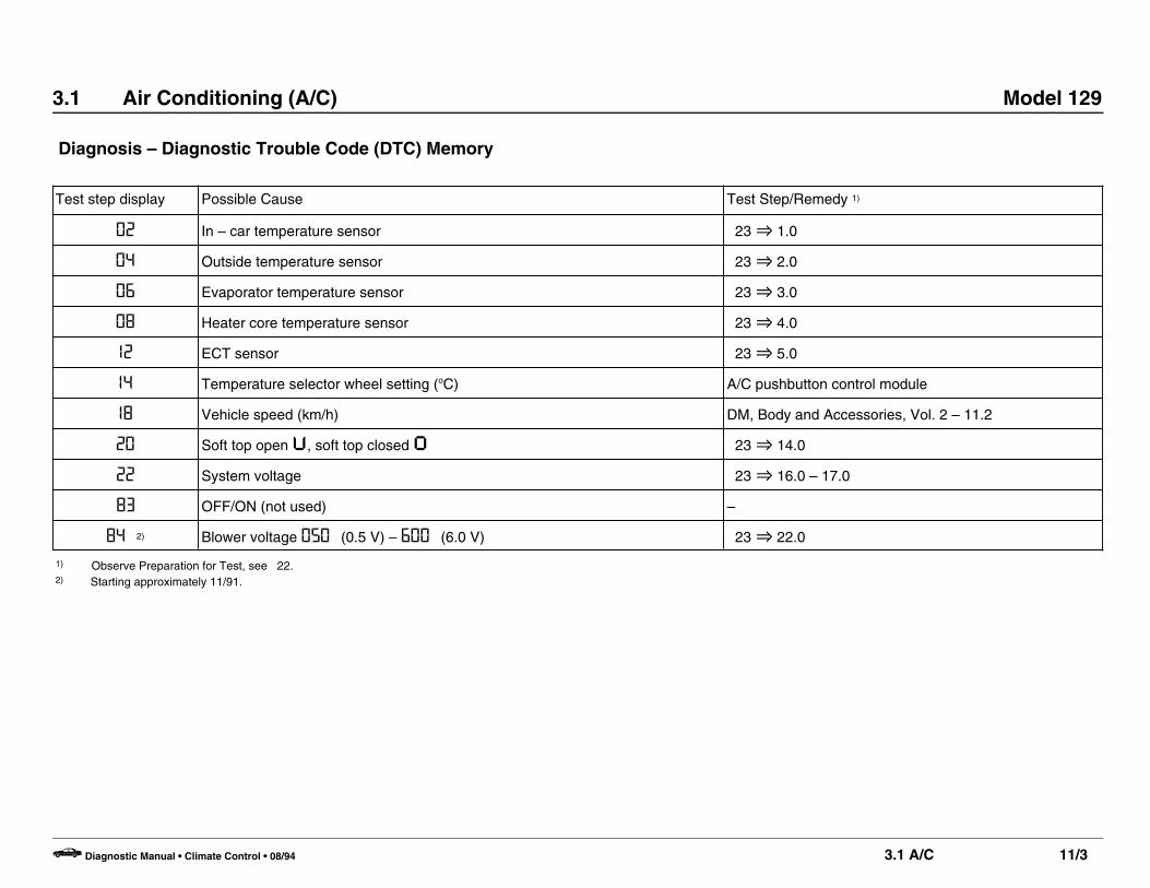
P83-2094-13C
Preparation for Test• Check in – car temperature sensor aspiration blower by placing a small piece of paper
(approx. ” square) over aspirator vent grille with ignition “ON” (arrow, Figure 1). If there issufficient ventilation the paper will remain on the vent grille, if not check aspiration blower forvoltage supply and function.
• Remove A/C pushbutton control module (N22).• Remove storage compartment just below radio.• Connect socket box test cable to left connector of wiring harness. The pushbutton control
module remains disconnected until test step 6.0.
Figure 1
Special Tools
20-pin test cable
129 589 03 63 00
35-pin socket box
124 589 00 21 00
Conventional tools, test equipment
Description Brand, model, etc.
Multimeter 1) Fluke models 23, 83, 85, 87
1) Available through the MBUSA Standard Equipment Program.
b Diagnostic Manual • Climate Control • 08/94 3.1 A/C 22/1

3.1 Air Conditioning (A/C) Model 129
Electrical Test Program – Test
O A Test scope Test connection Test condition Nominal value Possible cause/Remedy
1.0 2
3
In–car temperature sensorwith aspirator blower (B10/4)Resistance
19
11 w
N22k
u
b
20
L 20
k on left connector (1)
Ignition: OFFDisconnect test cable frompushbutton control module
oC k]10 18.3 – 21.515 15.2 – 17.520 11.5 – 13.525 9.5 – 10.530 7.5 – 8.535 6.0 – 7.040 4.5 – 5.545 3.5 – 4.5
Wires from pushbutton controlmodule (N22) to sensor B10/4 viaconnector (X85/2),B10/4.
2.0 4
5
Outside temperaturesensor (B10/5)Resistance 19
12 w
N22k
u
b
20
L 20
k on left connector (1)
Ignition: OFFDisconnect test cable frompushbutton control module
oC k]10 5.0 – 6.015 4.0 – 4.620 3.1 – 3.925 2.4 – 3.030 1.9 – 2.335 1.6 – 2.040 1.4 – 1.645 1.1 – 1.3
Wires from pushbutton controlmodule (N22) to sensor B10/5,B10/5.
b Diagnostic Manual • Climate Control • 07/96 3.1 A/C 23/1

3.1 Air Conditioning (A/C) Model 129
Electrical Test Program – Test
O A Test scope Test connection Test condition Nominal value Possible cause/Remedy
3.0 6
7
Evaporator temperaturesensor (B10/6) 1)
Resistance 19
8 w
N22k
u
b
20
L 20
k on left connector (1)
Ignition: OFFDisconnect test cable frompushbutton control module
oC k] 0 8.1 – 9.9 5 6.3 – 7.710 5.0 – 6.015 4.0 – 4.620 3.1 – 3.925 2.4 – 3.030 1.9 – 2.335 1.6 – 2.040 1.4 – 1.645 1.1 – 1.3
Wires from pushbutton controlmodule (N22) to sensor B10/6,B10/6.
4.0 8
9
Heater core temperaturesensor (B10/1)Resistance 19
10 w
N22k
u
b
20
L 20
k on left connector (1)
Ignition: OFFDisconnect test cable frompushbutton control module
oC k]10 18.3 – 21.515 15.2 – 17.520 11.5 – 13.525 9.5 – 10.530 7.5 – 8.535 6.0 – 7.040 4.5 – 5.545 3.5 – 4.5
Wires from pushbutton controlmodule (N22) to sensor B10/1,B10/1.
1) If the A/C system was in use immediately before the test, the temperature at the evaporator temperature sensor will be lower than the outside air temperature.
b Diagnostic Manual • Climate Control • 07/96 3.1 A/C 23/2

3.1 Air Conditioning (A/C) Model 129
Electrical Test Program – Test
O A Test scope Test connection Test condition Nominal value Possible cause/Remedy
5.0 I2
I3
ECT sensor (A/C)Resistance
19
7 w
N22k
u
b
20
L 20
k on left connector (1)
Ignition: OFFDisconnect test cable frompushbutton control module
oC ]
20 5000 – 800060 900 – 180085 460 – 650
100 300 – 400110 230 – 290120 180 – 220130 135 – 175
Wires from pushbutton controlmodule (N22) to sensor B10/8,B10/8.
b Diagnostic Manual • Climate Control • 07/96 3.1 A/C 23/3

3.1 Air Conditioning (A/C) Model 129
Electrical Test Program – Test
O A Test scope Test connection Test condition Nominal value Possible cause/Remedy
6.0 20
2I
Center and side air outletflap control module, leftair outlet adjuster (N18/2r1)Voltage
20 w
N22k
c L 16
k on left connector (1)Move left air outlet adjustercompletely to the right(outlet closed)
completely to the left(outlet open)
0.6 – 0.9 V
continuous, nosteps
3.9 – 4.5 V
Wires from control module (N22)to left air outlet adjuster (N18/2r1),Center and side air outlet flapcontrol module (N18/2).
7.0 I6
I7
Center and side air outletflap control module, centerair outlet adjuster (N18/2r2)Voltage
20 w
N22k
c L 18
k on left connector (1)Move center air outletadjuster completely to theright (outlet closed)
completely to the left(outlet open)
0.6 – 0.9 V
continuous, nosteps
3.9 – 4.5 V
Wires from N22 to center air outletadjuster (N18/2r2),N18/2.
8.0 24
25
Center and side air outletflap control module, rightair outlet adjuster (N18/2r3)Voltage
20 w
N22k
c L 14
k on left connector (1)Move right air outletadjuster completely to theright (outlet closed)
completely to the left(outlet open)
0.6 – 0.9 V
continuous, nosteps
3.9 – 4.5 V
Wires from N22 to right air outlet adjuster (N18/2r3),N18/2.
b Diagnostic Manual • Climate Control • 07/96 3.1 A/C 23/4

3.1 Air Conditioning (A/C) Model 129
Electrical Test Program – Test
O A Test scope Test connection Test condition Nominal value Possible cause/Remedy
9.0 Center and side air outletflap control module,pushbutton “cold” (N18/2s1)Voltage
19 w
N22k
c L 4
k on left connector (1)Press blue switch oncenter air outlet and hold
< 0.1 V Wires from N22 to coldpushbutton switch (N18/2s1),Center and side air outlet flapcontrol module (N18/2).
10.0 Center and side air outletflap control module,pushbutton “warm” (N18/2s2)Voltage
19 w
N22k
c L 3
k on left connector (1)Press red switch on centerair outlet and hold
< 0.1 V Wires from N22 to coldpushbutton switch (N18/2s2),N18/2.
11.0 22
23
Left air outlet feedbackpotentiometer (R23/1)Voltage 20 w
N22k
c L 15
k on left connector (1)Move left air outlet adjustercompletely to the right(outlet closed)
completely to the left(outlet open)
0.7 – 1.1 V
Continuous, nosteps
3.5 – 4.8 V
Wires from N22 to feedbackpotentiometer (R23/1),R23/1, Incorrect adjustment ordefective, replace vacuumelement.
12.0 I8
I9
Center air outlet feedbackpotentiometer (R23/3)Voltage 20 w
N22k
c L 17
k on left connector (1)Move center air outletadjuster completely to theright (outlet closed)
completely to the left(outlet open)
0.7 – 1.1 V
Continuous, nosteps
3.5 – 4.8 V
Wires from N22 to feedbackpotentiometer (R23/3),R23/3, incorrect adjustment ordefective, replace vacuumelement.
b Diagnostic Manual • Climate Control • 07/96 3.1 A/C 23/5
3.1 Air Conditioning (A/C) Model 129
Electrical Test Program – Test
O A Test scope Test connection Test condition Nominal value Possible cause/Remedy
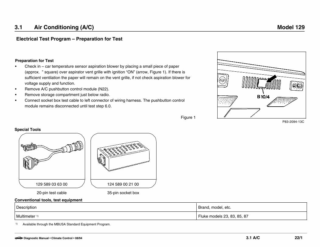
13.0 26
27
Right air outlet feedbackpotentiometer (R23/2)Voltage 20 w
N22k
c L 13
k on left connector (1)Move right air outletadjuster completely to theright (outlet closed)
completely to the left(outlet open)
0.7 – 1.1 V
Continuous, nosteps
3.5 – 4.8 V
Wires from N22 to feedbackpotentiometer (R23/2),R23/2, incorrect adjustment ordefective, replace vacuumelement.
14.0 Left soft top fabric bowswitch group (A22)Voltage 19 w
N22k
c L 6
k on left connector (1)Soft top closed
Soft top open
< 0.1 V
> 10 V
Wires from N22 to left soft topbow switch group (A22) viaconnectors (X85/2, X18/3).
b Diagnostic Manual • Climate Control • 07/96 3.1 A/C 23/6

3.1 Air Conditioning (A/C) Model 129
Electrical Test Program – Test
Test Conditions
1. Ignition: OFF2. Disconnect both connectors from A/C pushbutton control
module (N22).3. Disconnect test cable from left connector and reconnect to right
connector.
O A Test scope Test connection Test condition Nominal value Possible cause/Remedy
15.0 3 Ior
7 I
Monovalve (Y19)
18 w
N22k
b L 20
11 – 19 ] Wires from N22 to Y19,Y19.
b Diagnostic Manual • Climate Control • 07/96 3.1 A/C 23/7

3.1 Air Conditioning (A/C) Model 129
Electrical Test Program – Test
Test Conditions
1. Connect test cable to right connector of A/C pushbutton controlmodule (N22).
2. Connect wiring harness to left connector of A/C pushbutton controlmodule.
3. Ignition: ON
O A Test scope Test connection Test condition Nominal value Possible cause/Remedy
16.0 A/C pushbutton controlmodule (N22)Voltage supply (circuit 30) o c
N22kL 1
k on right connector (2) > 10 V Fuse 10 (F1–10), circuit 30,Wires from N22 to fuse F1-10open.
17.0 A/C pushbutton controlmodule (N22)Voltage supply (circuit 15) o c
N22k
L 19
k on right connector (2) > 10 V Fuse 7 (F1–7), circuit 15,Wires from N22 to fuse F1-7open.
18.0 A/C pushbutton controlmodule (N22)Voltage supply, output o c
N22k
L 20
k on right connector (2) > 10 V N22.
19.0 Mono valve (Y19)Ground connection
18 w
N22k
c L 20
k on right connectorTemperature selector(2)wheel set at “MIN”.
After 10seconds > 10 V
N22.
b Diagnostic Manual • Climate Control • 07/96 3.1 A/C 23/8

3.1 Air Conditioning (A/C) Model 129
Electrical Test Program – Test
O A Test scope Test connection Test condition Nominal value Possible cause/Remedy
20.0 30
70
Auxiliary coolant pump(M13) and and additionalfunction test by manualtouchGround connection
16 w
N22k
c L 20
k on right connector (2)Temperature selectorwheel set at “MAX”
After approx. 50seconds> 10 V
A/C pushbutton control module (N22).
21.0 50 Switchover valve block (Y11)Data transfer 7 w
N22k
c L 20
k on right connector (2) Voltageoscillatesbetween 0 – 8 V
N22.
22.0 Electronic blower regulator (N29)Voltage supply o c
N22k
L 11
k on right connector (2)Blower speeds: 1
234
0.8 – 1.2 V1.8 – 2.2 V2.7 – 3.3 V> 5 V
N22.
b Diagnostic Manual • Climate Control • 07/96 3.1 A/C 23/9

3.1 Air Conditioning (A/C) Model 129
Electrical Test Program – Test
O A Test scope Test connection Test condition Nominal value Possible cause/Remedy
23.0 35
75
Auxiliary fan (M4)Stage 1
12 w
N22k
c L 20
k on right connector (2)Press aOutside temperature above 86 oF
> 10 Vand auxiliary fanrunning in stage 1
A/C pushbutton control module (N22).
24.0 34
74
Auxiliary fan (M4)Stage 2
13 w
N22k
c L 20
k on right connector (2)Disconnect and bridgeETC sensor plug (B10/8)
> 10 Vand auxiliary fanrunning in stage 2
N22.
25.0 33
73
A/C compressor (A9)Ground connection 1)
14 w
N22k
c L 20
k on right connector (2)Press a
After 10seconds > 10 V
N22.
1) If the A/C compressor does not engage, check compressor shut-off 24.
b Diagnostic Manual • Climate Control • 07/96 3.1 A/C 23/10

3.1 Air Conditioning (A/C) Model 129
Electrical Test Program – Component Locations (Compressor Shut-Off)
P83-0045-57
Figure 1A9 A/C compressorA9l1 RPM sensorF19–1 Fuse 1, circuit 15XF19–2 Fuse 2, circuit 30M13 Auxiliary coolant pumpN16 Engine systems control moduleN22 A/C pushbutton control moduleR15 Auxiliary fan preresistorS31/1 Dual function A/C compressor pressure switch
(OFF 2.0/30.0 bar, ON 2.6/22.0 bar)S32 Auxiliary fan/A/C compressor pressure switch
(OFF 15.0 bar/ON 20.0 bar)X85 Automatic A/C/engine harness connector (6-pole)
b Diagnostic Manual • Climate Control • 08/94 3.1 A/C 24/1

3.1 Air Conditioning (A/C) Model 129
Electrical Test Program – Preparation for Test (Compressor Shut-Off)
• Check ground connection for A/C pushbutton control module (N22) byturning ignition “ON” and pressing a.Connect voltmeter ( + ) to terminal block, terminal 30/30U/61e/87L(X4/10) and test both connections of dual function A/C compressorpressure switch (S31/1) in series for ground.If there is no ground signal on either connection test the A/Ccompressor signal ( 23 O 25.0).If there is a ground signal to only one of the connections, test A/Csystem pressure. If the pressure is above 3 bar, replace dual functionA/C compressor pressure switch (S31/1). If the pressure is below 2bar, add 200 g refrigerant (R12 or R134a). Check for leaks and repaairif necessary (see connection diagram for signal test).
Special Tool
22-pin test cable
129 589 05 63 00
35-pin socket box
124 589 00 21 00
Conventional tools, test equipment
Description Brand, model, etc.
Multimeter 1) Fluke models 23, 83, 85, 87
1) Available through the MBUSA Standard Equipment Program.
b Diagnostic Manual • Climate Control • 08/94 3.1 A/C 25/1

3.1 Air Conditioning (A/C) Model 129
Electrical Test Program – Preparation for Test (Compressor Shut-Off)
P83-0033-57
Connection Diagram – Signal Test
Figure 1R15 Auxiliary fan preresistorS31/1 Dual function A/C compressor pressure switch
(OFF 2.0/30.0 bar, ON 2.6/22.0 bar)S32 Auxiliary fan/A/C compressor pressure switch
(OFF 15.0 bar/ON 20.0 bar)X4/10 Terminal block (circuit 30/30Ü/61e/87L) (6-pole)
b Diagnostic Manual • Climate Control • 08/94 3.1 A/C 25/2

3.1 Air Conditioning (A/C) Model 129
Electrical Test Program – Preparation for Test (Compressor Shut-Off)
P83-0043-57
Connection Diagram – Compressor Shut-Off Test
Figure 2002 Test cable003 Multimeter004 Socket boxN16 Engine systems control module
b Diagnostic Manual • Climate Control • 08/94 3.1 A/C 25/3

3.1 Air Conditioning (A/C) Model 129
Electrical Test Program – Test (Compressor Shut-Off)
O A Test scope Test connection Test condition Nominal value Possible cause/Remedy
1.0 Engine systems controlmodule (N16)Voltage supply 4 w
N16E
c L 21
Ignition: ON > 10 V Fuse B blown,Wiring.
2.0 A/C pushbutton controlmodule (N22)Ground connection 3 w
N16E
c L 21
Ignition: ONEngage compressor bypressing a
> 10 V Wiring.
3.0 A/C compressor,electromagnetic clutch(A9k1) 21
N16E
u 22
Engine: at Idle Compressormust run
Wiring,A9k1.
4.0 A/C compressor, RPMsensor (A9l1)
215 w
N16E
uf
22L 6
Engine: at Idle 0.25 V~ Wiring,O 4.1,A/C compressor (A9).
4.1 Resistance5 w
A9l1b L 6
Disconnect enginesystems control module(N16) from E
530 – 900 ]
5.0 RPM signal (TD or TN)
4 w
N16E
c L 16
Engine: at Idle 5.5 – 12 V Wiring from DI control module(N1/3) to engine systems controlmodule (N16).
b Diagnostic Manual • Climate Control • 08/94 3.1 A/C 26/1