Embed Size (px)
Citation preview


WARNING
HIGH PRESSURE SPRAY CAN CAUSE SERIOUS INJURY.
General SafetyThis equipment generates very high fluid pressure. Spray fromthe gun, leaks or ruptured components can inject fluidthrough your skin and into your body and cause extremelyserious bodily injury, including the need for amputation. Also,fluid injected or splashed into the eyes can cause seriousdamage.
NEVER point the spray gun at anyone or at any part of thebody. NEVER put hand or fingers over the spray tip. NEVERtry to “blow back” paint; this is NOT an air spray system.
ALWAYS have the tip guard in place on the spray gun whenspraying.
Spray Gun Safety DevicesBe sure all gun safety devices are operating properly beforeeach use. Do not remove or modify any part of the gun; thiscan cause a malfunction and result in serious bodily injury.
Safety LatchWhenever you stop spraying, even for a moment, always setthe gun safety latch in the closed or “safe” position, makingthe gun inoperative. Failure to set the safety latch can result inaccidental triggering of the gun.
DiffuserThe gun diffuser breaks up spray and reduces the risk of injec-tion when the tio is not installed. Check diffuser operation
ALWAYS follow the Pressure Relief Procedur?, . below,before cleaning or removing the spray tip or servlcrng anysystem equipment.
NEVER try to stop or deflect leaks with your hand or body.
regularly. Follow’ the Pressure Relief Procedure,’ below,then remove the spray tip. Aim the gun into a metal pail,holding the gun firmly to the pail. Using the lowest possiblepressure, trigger the gun. If the fluid emitted Is not diffused in-to an irregular stream, replace the diffuser immediately.
Be sure equipment safety devices are operating properlybefore each use.
Medical TreatmentIf any fluid ap ears to enetrate our skrh e t
EMEhENCY hEDICAi CAR6 &T ONCE.DO NOT TREAT AS A SIMPLE CUT.
Tell the doctor exactly what fluid was injected. For treatmentinstructions, have your doctor call the
NATIONAL POISON CENTEP NETWORK(412)681-6668 .
Tip GuardALWAYS have the tip guard in place on the spray gun whilespraying. The tip guard alerts you to the injection hazard andhelps prevent accidentally placing your fingers or any part ofyour body close to the spray tip.
Spray Tip SafetyUse extreme caution when cleaning or changing spray tips. Ifthe spray tip clogs while spraying, engage the gun safety latchimmediately. ALWAYS follow the Pressure Relief Pro-cedure and then remove the spray tip to clean it.
,-
rNEVER wipe off build up around the spray tip until pressure isfully relieved and the gun safety latch is engaged.
Pressure Relief ProcedureTo reduce the risk of serious bodily injury, including injection or injury from moving parts or electric shock, always follow thisprocedure whenever you shut off the sprayer, when checking or servicing any part of the spray system, when installing, clean-ing or changing spray tips, and whenever you stop spraying. (1) Engage the gun safety latch. (2) Turn the ON/OFF switch toOFF. (3) Unplug the power supply cord. (4) Disengage the gun safety latch. (5) Hold a metal part of the gun firmly to the side ofa metal pail, and trigger the gun to relieve pressure. (6) Engage the gun safety latch. (7) Open the drain valve, having a containerready to catch the drainage. (8) Leave the drain valve open until you are ready to spray again.
If you suspect that the spray tip or hose is completely clogged, or that pressure has not been fully relieved after following thesteps above, VERY SLOWLY loosen the tip guard retaining nut or hose end coupling and relieve pressure gradually, then loosencompletely. Now clear the tip or hose.
ENGAGE SAFETY TURN SWITCH TO OFF UNPLUG CORD
DISENGAGE SAFETYAND TRIGGER GUN;ENGAGE SAFETY AGAIN OPEN DRAIN VALVE
2 307460
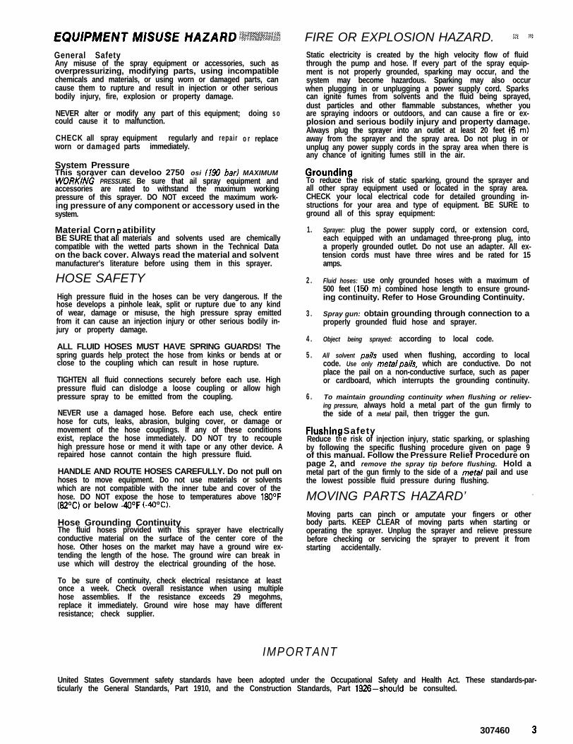
General SafetyAny misuse of the spray equipment or accessories, such asoverpressurizing, modifying parts, using incompatiblechemicals and materials, or using worn or damaged parts, cancause them to rupture and result in injection or other seriousbodily injury, fire, explosion or property damage.
NEVER alter or modify any partcould cause it to malfunction.
of this equipment; doing s o
CHECK all spray equipment regularlyworn or damaged parts immediately.
and repair o r replace
System PressureThis soraver can develoo 2750 osi 173J bar) MAXIMUMWORkINk PRESSURE. Be sure that ail spray equipment andaccessories are rated to withstand the maximum workingpressure of this sprayer. DO NOT exceed the maximum work-ing pressure of any component or accessory used in thesystem.
Material CornPBE SURE that al
atibilitymaterials and solvents used are chemically
compatible with the wetted parts shown in the Technical Dataon the back cover. Always read the material and solventmanufacturer’s literature before using them in this sprayer.
HOSE SAFETY 2 .
High pressure fluid in the hoses can be very dangerous. If thehose develops a pinhole leak, split or rupture due to any kindof wear, damage or misuse, the high pressure spray emittedfrom it can cause an injection injury or other serious bodily in-jury or property damage.
ALL FLUID HOSES MUST HAVE SPRING GUARDS! Thespring guards help protect the hose from kinks or bends at orclose to the coupling which can result in hose rupture.
TIGHTEN all fluid connections securely before each use. Highpressure fluid can dislodge a loose coupling or allow highpressure spray to be emitted from the coupling.
NEVER use a damaged hose. Before each use, check entirehose for cuts, leaks, abrasion, bulging cover, or damage ormovement of the hose couplings. If any of these conditionsexist, replace the hose immediately. DO NOT try to recouplehigh pressure hose or mend it with tape or any other device. Arepaired hose cannot contain the high pressure fluid.
HANDLE AND ROUTE HOSES CAREFULLY. Do not pull onhoses to move equipment. Do not use materials or solventswhich are not compatible with the inner tube and cover of thehose. DO NOT expose the hose to temperatures above WOOFW°C) or below -4OOF (-4OOC).
Hose Grounding ContinuityThe fluid hoses provided with this sprayer have electricallyconductive material on the surface of the center core of thehose. Other hoses on the market may have a ground wire ex-tending the length of the hose. The ground wire can break inuse which will destroy the electrical grounding of the hose.
To be sure of continuity, check electrical resistance at leastonce a week. Check overall resistance when using multiplehose assemblies. If the resistance exceeds 29 megohms,replace it immediately. Ground wire hose may have differentresistance; check supplier.
FIRE OR EXPLOSION HAZARD. .‘- (.lStatic electricity is created by the high velocity flow of fluidthrough the pump and hose. If every part of the spray equip-ment is not properly grounded, sparking may occur, and thesystem may become hazardous. Sparking may also occurwhen plugging in or unplugging a power supply cord. Sparkscan ignite fumes from solvents and the fluid being sprayed,dust particles and other flammable substances, whether youare spraying indoors or outdoors, and can cause a fire or ex-plosion and serious bodily injury and property damage.Always plug the sprayer into an outlet at least 20 feet (6 m)away from the sprayer and the spray area. Do not plug in orunplug any power supply cords in the spray area when there isany chance of igniting fumes still in the air.
GroundinfTo reduce t e risk of static sparking, ground the sprayer and
all other spray equipment used or located in the spray area.CHECK your local electrical code for detailed grounding in-structions for your area and type of equipment. BE SURE toground all of this spray equipment:
1.
3 .
4 .
5 .
6 .
Sprayer: plug the power supply cord, or extension cord,each equipped with an undamaged three-prong plug, intoa properly grounded outlet. Do not use an adapter. All ex-tension cords must have three wires and be rated for 15amps.
Fluid hoses: use only grounded hoses with a maximum of500 feet (150 m) combined hose length to ensure ground-ing continuity. Refer to Hose Grounding Continuity.
Spray gun: obtain grounding through connection to aproperly grounded fluid hose and sprayer.
Object being sprayed: according to local code.
All solvent pails used when flushing, according to localcode. Use only metalpails, which are conductive. Do notplace the pail on a non-conductive surface, such as paperor cardboard, which interrupts the grounding continuity.
To maintain grounding continuity when flushing or reliev-ing pressure, always hold a metal part of the gun firmly tothe side of a metal pail, then trigger the gun.
Flushin Safetyi!Reduce t e risk of injection injury, static sparking, or splashing
by following the specific flushing procedure given on page 9of this manual. Follow the Pressure Relief Procedure onpage 2, and remove the spray tip before flushing. Hold ametal part of the gun firmly to the side of a metal pail and usethe lowest possible fluid pressure during flushing.
MOVING PARTS HAZARD’ . .
Moving parts can pinch or amputate your fingers or otherbody parts. KEEP CLEAR of moving parts when starting oroperating the sprayer. Unplug the sprayer and relieve pressurebefore checking or servicing the sprayer to prevent it fromstarting accidentally.
IMPORTANT
United States Government safety standards have been adopted under the Occupational Safety and Health Act. These standards-par-ticularly the General Standards, Part 1910, and the Construction Standards, Part 1926-should be consulted.
307460 3

A VERTISSEMENT
La pulv&isation A haute pression peut causer des blessures tr&s graves.R6serv6 exclusivement & I’usage professionnel. Observer toutes les consignes de s&wit&
Bien lire et bien comprendre tous les manuels d’instructions avant d’utiliser le mat6riel.
Consignes g6n6rales de skuritdCet appareil produit un fluide 8 tres haute pression. Le fluidepulverise par le pistolet ou le fluide sous pression provenant defuites ou de ruptures peut penetrer sous la peau ou a I’interieurdu corps et entrainer des blessures tres graves, voir mQme uneamputation. MQme sans Qtre sous pression, le fluide bclabous-sant ou entrant dans les yeux peut aussi entrainer desblessures graves.NE JAMAIS pointer le pistolet vers quelqu’un ou vers une par-tie quelconque du corps. NE JAMAIS mettre la main ou lesdoigts sur I’ajutage du pulverisateur. NE JAMAIS essayer de“refouler” la peinture. Cet appareil N’est PAS un compresseurpneumatique.TOUJOURS garder la protection de I’ajutage en place sur lepistolet pendant la pulverisation.TOUJOURS observer la March g Suivre pour D6tendre laPression don&e plus loin, avant de nettoyer ou d’enleverI’ajutage du pulverisateur, ou d’effectuer un travail quelcon-que sur une partie de I’appareil.
NE JAMAIS essayer d’arrQter ou de devier les fuites avec lamain ou le corps.Avant chaque utilisation, bien s’assurer que les dispositifs desecurite fonct ionnent correctement.
Soins mddicauxEn cas de pen&ration de fluide sous la peau:
DEMANDER IMMEDIATEMENT DES SOINSMEDICAUX D’URGENCE.
NE PAS SOIGNER CE7TE BLESSURE COMMEUNE SIMPLE COUPURE.
Dire exactement au medecin quel type de liquide a 6te inject&Pour avoir des instructions concernant le traitement ap-proprie, dire au medecin d’appeler leCENTRE ANTI-POISON SUIVANT:
NATIONAL POISON CENTER NETWORK(412)681-6669
enlever ni modifier une partie quelconque du pistolet; ceci ris-querait d’entrainer un mauvais fonctionnement et desblessures graves.Verrou de s&wit&A chaque fois que I’on s’arrkte de pulveriser, mQme s’il s’agitd’un court instant, toujours mettre le verrou de securite dupistolet sur la position “fermee” ou “securite” (“safe”) pourempkher le pistolet de fonctionner. Si le verrou de securiten’est pas mis, le pistolet peut se dtklencher accidentellement.DiffuserLe diffuseur du pistolet sert B diviser le jet et a reduire les ris-ques d’injection accidentelle quand I’ajutage n’est pas enplace. Verifier le fonctionnement du diffuseur regulierement.Pour cette verification, detendre la pression en observant laMarche a Suivre pour Ddtendre la Pression donnee plusloin puis enlever I’ajutage du pulverisateur. Pointer le pistoletdans un seau en metal, en le maintenant fermement contre leseau. Puis, en utilisant la pression la plus faible possible, ap-puyer sur la gachette du pistolet. Si le fluide projete n’estpasdiffuse sous forme de jet irregulier, remplacer immediatementle diffuseur.
Protection de l’aju tageTOUJOURS maintenir la protection de I’ajutage en place sur f epistolet du pulverisateur pendant la pulverisation. La protec-tion de I’ajutage attire I’attention sur les risques d’injection etcontribue B eviter que les doigts ou une partie quelconque ducorps ne passe accidentel lement B proximite immediate deI’ajutage du pulverisateur.
Consianes de skurit4 concernant I’ajutage dupulvklsateurFaire extramement attention B l’occasion du nettoyage ou duremplacement des ajutages du pulverisateur. Si l’ajutage sebouche pendant la pulverisation, mettre immediatement leverrou de securite du pistolet. TOUJOURS bien observer laMarche g Suivre pour Ddtendre la Pression puis enleverI’ajutage du pulverisateur pour le nettoyer.
Avant chaque utilisation, bien s’assure que tous les dispositifsde securite du pistolet fonctionnent correctement. Ne pas
NE JAMAIS essuyer ce qui s’est accumule autour de I’ajutagedu pulverisateur avant que la pression ne soit completementtombee et que le verrou de securite du pistolet ne soit engage.
Marche A Suivre pour D6tendre la PressionPour reduire les risques de blessures graves, y compris les blessures par injection de fluide ou celles causees par des pieces enmouvement ou par electrocution, toujours bien observer cette marche a suivre B chaque fois que I’on arrQte le pulverisateur, BI’occasion de la verification ou de la reparation d’une piece de I’appareil de pulverisation, 8 I’occasion de I’installation, du net-toyage ou du remplacement des ajutages et d’une man&e g&n&ale a chaque arr9t. 1) Engager le verrou de securite du pistolet.2) Mettre I’interrupteur Marche-Arrat sur ARRET (“OFF”). 3) Debrancher le cordon d’alimentation. 4) Desengager le verrou desecurite du pistolet. 5) En maintenant une partie metallique du pistolet fermement appuyee contre le c&e d’un seau en metal,appuyer sur la gachette du pistolet pour liberer la pression. 6) Engager le verrou de securite du pistolet. 7) Ouvrir le robinet depurge en prenant soin d’avoir un recipient prQt B recuperer le liquide. 8) Laisser le robinet de purge ouvert jusqu’a ce que lepulverisateur soit de nouveau prQt a &re utilise.Sil’on soupconne que l’ajutage du pulvkisateur ou le tuvau est complktement bouchh, ou que la pression n’a pas BttS complkte-ment lib&&e apr&s avoir proc&d& aux opkrations ci-dessus, desserrer TRES LENTEMENT l’ecrou de retenue de la protection deI’ajutage ou le raccord du bout du tuyau et liberer progressivement la pression, puis terminer le desserrage. On peut maintenantdebaucher I’ajutage ou le tuyau.
M A
1 2 3 ‘L&6 7

RISQUES EN CAS DE MAUVAISE UTILISATION DU MATERIELConsignes g6n&ales de skurit4Toute utilisation anormale de I’appareil de pulverisation ou desaccessoires comme, par exemple, la mise sous une pressionexcessive, les modifications de pieces, I’utilisation de produitschimiques et de matieres incompatibles et I’utilisation depieces us&es ou abimees peut causer des deg&s B I’appareil oudes ruptures de pieces et entrainer une injection de liquide oud’autres blessures serieuses, un incendie, une explosion oud’autres degats.
NE JAMAIS alterer ou modifier une piece de cet appareil; cecirisquerait d’entrainer son mauvais fonctionnement.
VERIFIER regulierement tout I’appareil de pulverisation et sesequipements et &parer ou remplacer immediatement lespieces u&es ou abimees.
MESURES DE SECURITE CONCERNANT LESLe fluide a haute pression circulant dans les tuyaux peut &retres dangereux. En cas de fuite sur le tuyau, mQme minuscule,de fissure, dechirure ou rupture a la suite de I’usure, de degfitsou d’une mauvaise utilisation, les projections de fluide hautepression qui en proviennent peuvent entrainer des blessuresgraves par penetration sous la peau ou par contact, ainsi quedes deggts materiels.
TOUS LES TUYAUX FLEXIBLES DOIVENT AVOIR DESRESSORTS SPIRALE DE PROTECTION! Les spirales deprotection contribuent 8 eviter la formation de pliures, deboucles ou de noeuds sur les tuyaux qui pourraient entrainer larupture du tuyau 8 I’endroit du raccord ou a son voisinage.
SERRER FERMEMENT tous les raccords avant chaque utilisa-tion. Le fluide sous pression peut faire sauter un raccorddesserre ou produire un jet a haute pression s’echappant par leraccord.
NE JAMAIS utiliser un tuyau endommage. Avant chaqueutilisation, verifier entierement chaque tuyau pour deceler lescoupures, fuites, abrasions, boursouflures de I’enveloppe outoute autre deterioration ou jeu des raccords. Si I’on constateI’une de ces deteriorations, il faut remplacer le tuyau im-mediatement. NE PAS essayer de refaire le raccord d’un tuyauhaute pression ni de reparer le tuyau avec du ruban adhesif ou
PressionCe pulverisateur peut produire une PRESS/ON MAXIMUM DETRAVAIL l&W bar 12750 lb/po.2). S’assurer que tous leselements du pulverisateur et ses accessoires sont concus pourresister a la pression maximum de travail de ce pulverisateur.NE PAS depasser la pression maximum de travail d’aucun deselements ou accessoires utilises avec cet appareil.
Compatibilit4 chimique des corpsBIEN S’ASSURER que tous les corps des solvants utilisessont chimiquement compatibles avec les parties mouilkes in-diquees dans les “Donnees techniques”, au dos de la couver-ture. Toujours lire soigneusement les documents et brochuresdu fabricant des mat&es et solvants utilises avant de s’en ser-vir dans ce pulverisateur.
T U Y A U X FLEXIBLESpar tout autre moyen. Un tuyau repare ne peut pas resister aufluide sous pression.
MANIPULER L E S T U Y A U X A V E C P R E C A U T I O N E TCHOISIR SOIGNEUSEMENT LEUR CHEMIN. Ne pas deplacerle materiel en tirant sur le tuyau. Ne pas utiliser de mat&es oude solvants qui ne sont pas compatibles avec I’enveloppe in-terieure ou exterieure du tuyau. NE PAS exposer le tuyau ades temperatures superieures a 82°C (18OOF) ou inferieures a-40°C (-4OOF).
Continuitd du circuit de mise A la terre des tuyauxLes tuyaux flexibles fournis avec ce pulverisateur ont une sur-face conductrice continue au coeur du tuyau. D’autres tuyauxvendus dans le commerce cornportent un fil de mise a la terreallant tout au long du tuyau. Ce fil de mise a la terre peut serompre a I’usage, ce qui supprime la mise a la terre du tuyau.
Pour &re certain de la continuite de la mise a la terre, il fautverifier la resistance Blectrique des tuyaux au moins une foispar semaine. Verifier aussi la resistance d’ensemble quand il ya plusieurs tuyaux assembltk Si la resistance depasse 29megohms, remplacer immediatement le tuyau. La resistancedes tuyaux mis a la terre par un fil peut Qtre differente; serenseigner aupres du fournisseur.
RISQUES D’INCENDIE OU D’EXPLOSIONDe l’electricite statique est produite par le passage du fluide agrande vitesse dans la pompe et dans les tuyaux. Si toutes lespieces de I’appareil de pulverisation ne sont pas convenable-ment reliees a la masse ou B la terre, des etincelles peuvent seproduire et I’appareil risque d’9tre dangereux. Des Btincellespeuvent egalement se produire a I’occasion du branchementou du debranchement du cordon d’alimentation. Les etincellessont suffisantes pour allumer les vapeurs de solvants et lefluide pulverise, les fines particules de poussiere ainsi qued’autres substances inflammables, quand on pulverise a I’in-terieur ou 8 I’exterieur, et elles peuvent causer un incendie ouune expiosion, ainsi que des blessures graves et des deggtsmateriels. Toujours brancher le pulverisateur dans une prise setrouvant a au moins 6 m (20 pieds) de I’appareil et de I’endroitoti se fait la pulverisation. Ne pas brancher ou debrancher uncordon d’alimentation quel qu’il soit dans la zone ou se fait lapulverisation quand il y a le moindre risque que des vapeursencore presentes dans I’air prennent feu.
Mise & la terre ou A la massePour reduire les risques de production d’etincelles d’electricitestatique, le pulverisateur et tous les equipements utilises ou setrouvant dans la zone de pulverisation doivent Qtre relies a laterre ou a la masse. Pour connaitre le detail des instructions demise ZI la terre dans la region et le type particulier d’equipe-ment, CONSULTER le code ou les reglementations electriqueslocales. S’ASSURER que tous les equipements de pulverisa-tion suivants sont bien relies a la terre:
2. Tuyaux flexibles: Afin d’assurer la continuite de la mise a laterre, n’utiliser que des tuyaux comportant une mise a la terre
\ ;.
e t a y a n t u n e l o n g u e u r m a x i m u m combinee d e 1 5 0 m(1500 pieds). Se reporter egalement au paragraphe “Con-tinuitb du circuit de mise A la terre des tuyaux”.3. Pistolet: Realiser la mise 8 la terre en le raccordant a untuyau flexible et a un pulverisateur deja convenablement reliesa la terre.
4. Objets, mattkiel ou surfaces recevant la pulv&isation:observer le code ou les reglementations locales.
5. Tous /es seaux de so&ants utilises pour le rincage: observerle code ou les reglementations locales. N’utiliser que des seauxm&a//iques conducteurs de l’electricite. Ne pas mettre le seausur une surface non conductrice comme sur du papier ou ducarton car cela interromprait la continuite le la mise a la terre.
6. Pour conserver la continuith de la mise B la terre quand onrince le matkriel ou quand on lib&e la pression, toujoursmaintenir une partie metallique du pistolet fermement appuyeecontre le cot& d’un seau en m&a/ puis appuyer sur la detentedu pistolet.
Mesures de Sdcurit4 concernant le RincagePour reduire les risques de blessures par penetration de lapeau et les risques dirs aux etincelles d’electricite statique ouaux eclaboussures, observer la marche a suivre pour le rincagedonnee a la page 9 de ce manuel. Observer la “Marche &Suivre pour Dbtendre la Pression” donnee a la page 4 enenlever l’ajutage du pulv&isateur avant le rincage. Maintenirune partie metallique du pistolet fermement appuyee contre letote d’un seau en m&al et utiliser la pression la plus faiblepossible pendant le rincage.
1. Pulwkisateur: Brancher le cordon d’alimentation ou larallonge qui doivent Qtre equip& d’une prise 8 3 fiches en bon&at, dans une prise de courant convenablement mise a laterre. Ne pas utiliser d’adaptateur. Toutes les rallonges doiventavoir 3 fils et &re prevues pour 15 amperes.
307460 5

ADVERTENCIA
EL ROCIADO A ALTA PRESION PUEDE CAUSAR GRAVES LESIONES.SOLO PARA US0 PROFESIONAL. RESPETE LOS AVISOS DE ADVERTENCIA.
Lea y entienda todo el manual de instrucciones antes de manejar el equipo.
PEUGRO DE Iff YECCION DE FLUID0Seguridad generalEste equip0 genera un fluid0 a una presion muy alta. Elrociado de la pistola, 10s escapes de fluid0 o roturas de 10scomponentes pueden inyectar fluid0 en la piel y el cuerpo ycausar lesiones extremadamente graves, incluyendo a veces lanecesidad de amputacibn. Tambien, el fluid0 i n y e c t a d o osalpicado en 10s ojos puede causar graves dafios.
NUNCA apuntar la pistola hacia alguien o alguna parte delcuerpo. NUNCA colocar la mano o 10s dedos encima de la bo-quilla. NUNCA tratar de “hater retornar la pintura”; este NOes un sistema de rociado de aire.
SIEMPRE tener colocado el protector de la boquilla en lapistola mientras se esta pulverizando.
SIEMPRE seguir el procedimiento de descarga de presibn,dado m& abjo, antes de limpiar o sacar la boquilla o de darservicio a cualiquier equip0 del sistema.
NUNCA tratar de parar o desviar 10s escapes con la mano o elcuerpo.
Asegurar que todos 10s aparatos de seguridad del equip0estan funcionando bien antes de cada uso.
Tratamiento medicoSi pareciera que un poco de fluid0 penetro la piel, conseguir
TRATAMIENTO MEDICO DE URGENCIA DEINMEDIATO.
NO TRATAR LA HERIDA COMO UN SIMPLE CORTE.Decir al medico exactamente cua fluid0 fue. Para instruc-ciones de tratamiento, pedir al medico que llame a la
CADENA DEL CENTRO NACIONAL DEENVENENAMIENTO
Aparatos de seguridad de la pistola pulverizadoraAsegurar que todos 10s aparatos protectores de la pistolaestan f unc ionando b i en an tes de cada uso. No sacar n imodificar ninguna pieza de la pistola pues podria causar elmalfuncionamiento de la misma con las consiguientes lesionespersonales.
Pestillo de segut-idadCada vez que se deje de pulverizar, aunque sea por un brevemomento, siempre colocar el pestillo de seguridad en laposition “cerrada”, lo que deja la pistola inoperante. El nohacerlo puede llevar al disparo imprevisto de la pistola.
DifusorEl difusor de la pistola dispersa el chorro pulverizado y reduceel riesgo de inyeccion cuando no esta instalada la boquilla.Revisar con regularidad el funcionamiento del difusor. Seguirel procedimiento de descarga de presibn, dado mas abajo,y despues sacar la boquilla. Apuntar la pistola a un baldemetalico, sosteniendola bien firme contra 61. Utilizando lapresion m&r bajo posible, disparar la pistola. Si el fluid0emitido no sale disperse en un chorro irregular, reemplazar deinmediato el difusor.
Protector de la boquillaSIEMPRE tener el protector de ia boquilla colocado en lapistola mientras se esta pulverizando. Este protector llama laatencion contra el peligro de inyeccibn y ayuda a prevenir lacolocacion accidental de 10s dedos o cualquier otra parte delcuerpo cerca de la boquilla.
Seguridad de la boquilla pulverizadoraTener mucho cuidado al limpiar o cambiar las boquillas. Sillegara a obstruirse mientras esta pulverizando, enganchar elpestillo de la pistola de inmediato. SIEMPRE seguir el pro-cedimiento de descarga de presih y despues sacar la bo-quilla para limpiarla.
NUNCA limpiar la acumulacion de pintura alrededor de la bo-quilla antes de que se haya descargado por complete lapresion y el pestillo este enganchado.
Procedimiento de descarga de presihPara reducir el riesgo de sufrir graves lesiones corporales, rncluyendo inyeccion o lesiones causadas por piezas en movimiento ochoque electrico, siempre seguir este procedimiento al apagar la maquina pulverizadora, al revisar o dar servicio a cualquier partedel sistema de pulverizacibn, al instalar, limpiar o cambiar las boquillas, y cada vez que se deja de pulverizar. (1) Enganchar elpestillo de la pistola. (2) Mover el interruptor electrico (ON/OFF) a la position OFF (apagado). (3) Desenchufar el cordonektrico. (4) Desenganchar el pestillo de la pistola. (5) Sujetar una parte mettilica de la pistola bien firme contra un balde demetal, y disparar la pistola para descargar la presibn. (6) Enganchar el pestillo de la pistola. (7) Abrir la valvula de drenaje y tenerlisto un reclipiente para recibir la pintura. (8) Dejar la valvula de drenaje abierta hasta que se este nuevamente listo parapulverizar.
Sise sospecha que la boquilla o la manguera est4 completamente obstruida, o que no se ha descargado por complete la presidndespuh de haber seguido elprocedimiento anterior, aflojar MUY LENTAMENTE la tuerca de retention del protector de la bo-quilla o acoplamiento de la punta de la manguera y descargar gradualmente la presibn, despues, aflojarlo por complete. Luego,despejar la boquilla o la manguera.
1 2 3 456 7
6 307460

PELIGRO POR MAL US0 DEL EQUIP0Seguridad eneralCualquier ma Buso del equip0 pulverizador o 10s accesorios, talcoma sobrepresurizacion, modificacibn de piezas, uso demateriales y productos quimicos incompatibles, o utilizationde piezas dafiadas o desgastadas, puede hacen que se rompany causen la inyeccion de fluid0 u otras lesiones corporalesgraves, incendio, explosion o dafion a la propiedad.
NUNCA alterar o modificar ningunahacerlo podria causar una averia.
p i e z a de este equipo; el
REVISAR con regularidad el equip0 pulverizador y reparar oreemplazar de inmediato las piezas dafiadas o desgastadas.
Presi6n del sistemaEsta pu lver i zadora puede desar ro l la r 190 bar ias (2756psi) de PRESION DE TRABAJO MAXIMA. Asegurar que todoel equip0 pulverizador y sus accesorios tienen la capacidadpara aguan ta r l a presibn m a x i m a d e t r a b a j o d e estapulverizadora. NO exceder la presion maxima de trabajo deningun componente o accesorio de este sistema.
Compatibilidad de materialASEGURAR que todos 10s materiales y solventes usados sonquimicamente compatibles con las piezas mojadas ilustradasen la hoja de datos tecnicos en la contratapa. Siempre leer lasinstrucciones del fabricante del material y solvente antes deusarlos en esta pulverizadora.
SEGURIDAD EN EL US0 DE LAS MANGUERASEl fluid0 que pasa a alta presion por las mangueras puede sermuy peligroso. Si en la manguera se desarrolla un escape pe-quefio, una rotura o rajadura debido a cualquier tipo dedesgaste, daiio o maltrato, el chorro a alta presion emitido poralli puede causar una lesion por inyeccion u otras lesiones cor-porales graves o dafion a la propiedad.
iTODAS L A S M A N G U E R A S PARA FLUIDOS TIENENQUE TENER GUARDAS DE RESORTE! Estas protegen lasmangueras contra dobleces o retorceduras en 10s acoplamien-tos o cerca de ellos, 10s que podrian traducirse en roturas de lamanguera.
Antes de usarlas, APRETAR bien firmes todas las conexiones.El fluid0 a alta presion puede desalojar un acoplamiento sueltoo dejar que por &I escape un chorro a alta presibn.
NUNCA usar una manguera que esta daiiada. Siempre,revisarla en busca de cortaduras, escapes, abrasion, cubiertaabultada, o acoplamientos sueltos o dafiados. Si llegara a en-contrarse cualquiera de estas condiciones, reemplazar de in-mediato la manguera. NO intentar reacoplar una manguera dealta presion o enmendarla con cinta adhesiva u otro materialsimilar. Una manguera que ha sido remendada no aguante elfluid0 a alta presion.
MANEJAR Y P A S A R CUIDADOSAMENTE L A SMANGUERAS. No tirar de las mangueras para mover elequipo. No usar materiales o solventes que Sean incompatiblescon el tubo interno y la cubierta dela manguera. NO exponerlas mangueras a temperaturas sobre 82°C (180°F) o bajo-40°C (-40°F).
Continuidad a tierra de la mangueraLas mangueras para fluidos provistas con esta pulverizadoratienen material electricamente conductive en la superficie delnlicleo central. Otras mangueras a la venta tienen a veces unalambre a tierra a todo el largo. Este alambre puede rompersecon el uso, destruyendose por lo tanto, la conexion a tierra dela manguera.
Corn0 precaution, revisar por lo menos una vez a la semana laresistencia electrica. Revisar la resistencia general al usar con-juntos de mangueras multiples. Si excede de 29 megaohmios,reemplazarla de inmediato. Las mangueras con alambre at ie r ra t ienen d i fe ren tes res is tenc ias ; consu l ta r con e lproveedor.
PELIGRO DE INCENDIO 0 EXPLOSIOhlEl flujo a alta velocidad del fluid0 al pasar por la bomba ymanguera crea electricidad estatica. Si todas las partes delequip0 pulverizador no tienen buena tierra, pueden ocurrirchispas, convirtiendo al sistema en algo peligroso. Tambien,pueden producirse chispas al enchufar o desenchufar el cor-don electrico. Estas chispas pueden inflamar 10s vapores de10s solventes y el chorro de fluid0 pulverizado, particulas depolvo y otras sustancias inflamables, sea al aire libre o bajotecho, lo que podria causar una explosion o incendio y graveslesiones corporales y dafios a la propiedad. Enchufar siemprela pulverizadora a un tomacorriente que se encuentre a por lomenos 6 m (20 pies) de la maquina y del area que se va arociar. No enchufar o desenchufar ningun cordon electrico enel lugar donde se esta rociando cuando todavia exista laposibilidad de que queden vapores inflamables en el aire.
Puesta a tierraPara reducir el riesgo de chispas estaticas, conectar a tierra lapulverizadora y todo el otro equip0 de pulverizar que se use ose encuentre en el lugar que se va a rociar. CONSULTAR elcddigo electrico de la localidad para las instrucciones sobre lasconexiones a tierra exigidas para la zona y tipo de equipo.A S E G U R A R d e c o n e c t a r a t i e r r a todo e s t e equip0pulverizador:
1. Pulverizadora: enchufar el cordon electrico, o cable exten-sor, cada uno con un enchuf de tres patas en buen estado, aun tomacorriente con puesta a tierra apropiado. No usar unadaptador. Totos 10s cables extensores tienen que tener treshilos y una capacidad de 15 amperios.
2. Mangueras para fluidos: usar solamente mangueras conp u e s t a a t i e r r a d e u n a l o n g i t u d c o m b i n a d a d e 1 5 0 mKiOO pies), para asegurar buena continuidad a tierra. Referirsetambien a l parrafo sobre cont inuidad a t ierra de lamanguera.
3 . Pistola: hater l a pues ta a t ie r ra conectandola a unamanguera de fluid0 y pulverizadora bien conectadas a tierra.
4. Objet0l o c a l .
que se estA rociando: d e conformidad con el cbdigo
5. Todos /OS baldes de solvente usados durante el lavado, deconformidad con el cbdigo local. Usar solamente baldes demetal, que Sean conductivos. No colocar el balde en unasuperficie no conductiva, coma papel o carton, que inter-rumpe la continuidad a tierra.
6. Para mantener la continuidad a tierra durante ei lavado odescarga de presih, siempre apoyar una parte metalica de lapistola bien firme contra el costado del balde de metal,despues apretar el gatillo.
Seguridad durante el lavadoReducir el riesgo de lesiones por inyeccion, chispas electricaso salpicaduras, s i g u i e n d o e l p r o c e d i m i e n t o d e lavadoespecifico dado en la pagina 9 de este manual. Seguir el pro-cedimiento de descarga de presibn en la pagina 6, y quitarla boquilla rociadora antes de lavar. Apoyar una parte metalicade la pistola bien firme contra el costado de un balde de metaly usar la presion mas baja posible de fluid0 durante el lavado.
PELIGRO DE LAS PIEZAS MOVILESLas piezas en movimiento pueden pinchar o amputar dedos uotras partes del cuerpo. MANTENERSE ALEJADO de laspiezas en movimiento durante el arranque o funcionamientode la pulverizadora. Desenchufar la pulverizadora y descargarla presion antes de revisarla o darle servicio, para impedir quearranque inesperadamente.
IMPORTANTSe han adoptado las normas de seguridad del gobierno de 10sEstados Unidos de Norteamerica bajo el Acta de Seguridad ySalud Ocupacional. Deberan consultarse estas normas, enespecial las Generales, Parte 1910, y las Normas de Construc-cibn, Parte 1926.
307-460 7

INSTALLATION \ . ’.’ , ” I ..’ I , . : .: .: I,:!.. . , , ,
r ON/OFF switch
Check the Gearcase OilRemove the fill plug (A) and ensure that the oil level isup to the fill plug opening. See Fig 1.
Connect the GunRemove the plastic cap plug from the filter (64) and con-nect the 50 ft (15 m) spray hose (67) to the l/4 npsm(m)filter outlet (B). Then connect the whip end hose (68)between the spray hose and the fluid inlet (C) of thegun. Do not use thread sealer. Do not install the spraytip yet; wait until after flushing the sprayer. The longerthe spray hose, the lower the delivery rate.
To avoid damaging the pressure control, whichCAUTION
may result in poor sprayer performance, followthese precautions:1. Always use nylon spray hose at least 50 ft
(15.2 m) long.2 . Never use wire braid hose at it is too rigid to
act as a pulsation dampener.3 . Never install any shutoff device between the
filter and the main hose. See Fig 1.4. Never plug the main filter outlet while the
sprayer is operating. \
8 307460
Fill Packing Nut/Wet CupFill the packing nut/wet cup (38) l/3 full with GraceThroat Seal Liquid (TSL) to help protect and prolongthe life of the pump’s throat packings.
Ei;;k Electrical Service and Plug In Power Supply
Be sure the electrical service is 120 V, 60 HzAc, 15 Amp(minimum) and that the outlet you use is properlygrounded. Use an extension cord which has 3 wires of12 gauge (minimum) size and a maximum of 100 ft (30.3m) long. Longer lengths may affect sprayer perfor-mance.
Plug in the SprayerBe sure the ON/OFF switch is OFF. Refer to Fig 1. Thenplug the cord into a grounded electrical outlet at least20 ft (6 m) away from the spray area.
WARNINGTo reduce the risk of static sparking, be sure toread and follow the grounding instructions givenon page 3 of this manual.
4
Set Pressure ControlTurn the pressure control knob (D) counterclockwise tothe lowest setting each time before you start the sprayerto help prolong the pump life.
Flush the PumpAn important part of the care and maintenance of yourEM 480 is proper flushing. See “Flushing Guidelines”on page 9 for “When to Flush” and “How to Flush”.

FLUSHING GUIDELINES
When To Flush .
1. Before using your new sprayer. Your new EM 480was factory tested in No. 10 motor oil and the oil wasleft in it to protect the parts.Before using water-based paint: Flush out the oilwith mineral spirits, then flush out the mineral spiritswith soapy water followed by a clean water rinse.Before using o&based paint: Flush out the oil withmineral spirits only.
2. Whenever you change the color of your paintsupply. Flush with a compatible solvent such asmineral spirits or water.
3. Whenever you change from water-based to oil-based paint. Flush with soapy water, then mineralspirits.
4. Whenever you change from oil-based to water-based paint. Flush with mineral spirits, then soapywater, followed by a clean water rinse.
5. Before you store your sprayer.When using water-based paint: Flush with water,then mineral spirits and leave the pump, hose, andgun filled with mineral spirits.When using o&based paint: Flush with mineralspirits and leave the pump, hose, and gun filled withmineral spirits.
6. Before you use your sprayer after storage.Before using water-based paint: Flush out mineralspirits with soapy water followed by a clean waterrinse.Before using o&based paint: Flush the mineral spiritsout and the unit is ready to use.
How To Flush. . . . ; .’ :: <>
1. Follow the Pressure Relief Procedure Warning onpage 2, then remove the spray tip.
\ WARNINGTo reduce the risk of an injection injury, alwaysremove the spray tip from the gun before flushing.
2. Remove the filter bowl and screen. See manual307-273, supplied. If the bowl is tight, remove thefilter assembly from the sprayer first. Install thebowl on the filter without the screen. Clean thescreen separately.
CAUTIONUsing excessive force to remove the filter bowlwhile still on the sprayer could rotate the pressurecontrol fittings and damage the bourdon tube.
\3 . Pour l/2 gallon (2 liters) of compatible solvent (see
“When to Flush”) into a bare metal pail. Put thepump suction tube in the pail.
4. Be sure the pressure control knob is set atminimum, then disengage the gun safety latch.
When you are flushing or relieving pressure,ALWAYS hold a metal part of the gun firmly to a
the risk of static sparking, which can cause fire or
5 . Point the spray gun into the metal pail, squeeze thetrigger, turn the sprayer to ON, and slowly turn thepressure control setting clockwise just until thesprayer starts. Always use the lowest possiblepressure.
6 . Keep the gun triggered until clean solvent comesfrom the nozzle. Release the trigger. Then open thefilter drain valve, which is connected to a drainvalve, and flush again to remove paint from thedrain tube.
7. Release the trigger and engage the gun safetylatch. Close the drain valve.
Fig
8.
9 .
1 0 .
1 1 .
12.
2
Check all fluid connections for leaks. If there areany leaks, follow the Pressure Relief ProcedureWarning, above, then tighten the connections.Start the sprayer again and check to be sure theleaking has stopped.
Remove the suction tube from the pail. Disengagethe gun safety latch and trigger the gun into a metalpail to force solvent from the hose. Do not let thepump run dry for more than 30 seconds to avoiddamaging the pump packings!
Engage the gun safety latch, turn the sprayer toOFF, and unplug the sprayer. Open the drain valve.
Unscrew the filter bowl (F) and reinstall the screen(G) so the stud of the filter support (H) protrudesthrough the end of the screen. Install the spring (E)on the stud, and reinstall the bowl, hand tight only.Be careful not to rotate or jar the pressure controlfittings.
If you flushed with mineral spirits and are going touse a water-based paint, you must flush again withsoapy water, followed by a clean water rinse.
307460 9

Prepare the PaintPrepare the paint as instructed by the manufacturer. Ifthe paint has been opened before, remove any skin thathas formed. Stir the paint thoroughly to dissolve anyhard pigments. Strain the paint through a fine nylonmesh bag (available at most paint dealers) to removeparticles that might clog the filter or the spray tip. This isprobably the most important step toward trouble-freespray painting.
Prime the SprayerPlug the power supply cord into a grounded, 3-prongoutlet. Close the drain valve. Put the paint suction tubeinto the pail of paint. Don’t install the spray tip in thegun yet! Disengage the gun safety latch and point thegun into a metal waste container. Squeeze the gun trig-ger, turn the ON-OFF switch to the ON position andlet the sprayer operate until all air is forced out of thesystem. Engage the gun safety latch.
NOTE: If the pump is hard to prime, turn on thesprayer and open the drain valve. Let thesprayer run until paint has filled the draintube (21). This method bleeds the air fromthe pump. Then release the gun safety latchand trigger the spray gun to prime the hose.Engage the gun safety latch.
Install the Spray Tip and Tip GuardFollow the Pressure Relief Procedure Warning, below.
Unscrew the retaining nut from the gun. Install theReverse-A-Clean III (90) spray housing with the tip in-stalled (see instruction manual 307321 or the instruc-tion label with the Reverse-A-Clean). Then tighten theReverse-A-Clean retaining nut by hand until snug. Final-ly, use a wrench and tighten the retaining nut l/4 turn.This is essential to prevent leaking.
For information about your airless gun, see instructionmanual 307633.
Adjust the Spray PatternAdjust the pressure control knob (D) so the fluidpressure completely atomizes the spray from the gun.Always use the lowest possible pressure to get thedesired results. See Fig 3.
Now test the spray pattern on a piece of light coloredpaper. The tip position determines the direction of thepattern width. To adjust the pattern, engage the gunsafety latch and loosen the retaining nut to position thetip so the groove is horizontal for a horizontal pattern orvertical for a vertical pattern. Once positioned, tightenthe retaining nut.
Fig 3 /
10 307460
Xeaning and Clearing the Spray TipWARNING
To reduce the risk of an injection injury, DO NOThold your hand, body, or a rag in front of the spraytip when cleaning or checking a clogged tip.Always point the gun toward the ground or into awaste container when checking to see if the tip isc l e a r .DO NOT try to “blow back” paint; this is NOT anair spray sprayer.DO NOT wipe build up off of the gun or tip untilpressure is relieved. See The Pressure Relief Pro-cedure Warning, below.
Clean out the front of the spray tip frequently during theday’s operation and at the end of the work day. Alwaysrelieve pressure according to the Pressure Relief Pro-cedure Warning, below. Then use a solvent soakedbrush to clean the spray tip and to keep material buildup from drying and clogging the spray tip.
If the spray tip clogs while spraying, release the spraygun trigger, engage the gun safety latch, and turn theReverse-A-Clean handle 18OO. See Fig 4. Disengage thegun safety latch and trigger the gun. Fluid pressureshould force the obstruction from the spray tip. Releasethe trigger, engage the gun safety latch, return the han-dle to the original position, and resume spraying.
ROTATEHANDLE
180”
Fig 4
Shutdown and Care of the Sprayer
WARNINGPressure Relief ProcedureTo reduce the risk of serious bodily injury, in-cluding injection or injury from moving parts orelectric shock, always follow this procedurewhenever you shut off the sprayer, when check-ing or servicing any part of the spray system,when installing, cleaning or changing spray tips,and whenever you stop spraying.1 . Engage the gun safety latch.2 . Turn the ON/OFF switch to OFF.3 . Unplug the power supply cord.4 . Disengage the gun safety latch.5 . Hold a metal part of the gun firmly to the side
of a metal pail, and trigger the gun to relievepressure.
6 . Engage the gun safety latch.7. Open the drian valve, having a container
ready to catch the drainage.8 . Leave the drain valve open until you are ready
to spray again.If you suspect that the spray tip or hose is com-ple tely clogged, or that pressure has not been fullyrelieved after following the steps above, VERYSLOWLY loosen the tip guard retaining nut orhose end coupling and relieve pressure gradually,then loosen completely. Now clear the tip or hoseobstruction.

Before each use, squirt one drop of oil onto the lowerpivot point (J) of the pump (33). See Fig 5.
For very short shutoff periods, relieve pressure, leavethe suction tube in the paint and clean the front of thespray tip.
Check the packing nut/wet cup (38) before each useand periodically when in use. Follow the Pressure ReliefProcedure Warning before checking or tightening. Thepacking nut should only be tight enough to stopleakage. Do not over tighten. Overtightening may causebinding and excessive wear on the packings.
Clean the outlet filter often and whenever the sprayer isstored. On the last workday of the week, flush all thepaint out of the sprayer. See “Flushing Guidelines,’ onpage 9. If you are using a paint that will dry overnight,flush the sprayer daily at shutdow’h.
Always push the suction tube onto the clip (13) on theside of the frame (6) and wrap the hose around thesprayer when storing it, even if only overnight, to helpprotect the hose from damage.
Do not store the sprayer with water in it. Even for over-night storage, you should fill the sprayer with mineralspirits. This prevents rust and greatly extends the life ofthe sprayer.
CAUTIONDo not let water freeze in the pressure control orpump in cold weather. Freezing could cause achange in the pressure control calibration or strip-ping of gears, resulting in loss of pressure orstallina.
Fig 5
Once a month, lubricate the needle bearing (36) in thedisplacement rod (34); use a grease gun to apply thegrease to the grease fitting (35). See Fig 5.
Periodically, or if the motor overheats, unplug thepower supply cord, follow the Pressure Relief Pro-cedure Warning on page 10, and clean all paint and dirtoff the motor. Change the gearcase oil at least once ayear, using Grace Gear Oil no. 206-230. The gearcaseholds 3 pints (1.4 liters). Don’t use hypoid grease.
307460 11
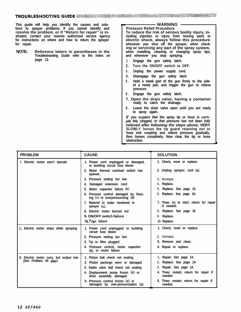
This guide will help you identify the causes and solu-tions to sprayer problems. If you cannot identify andresolve the problem, or if “Return for repair” is in-dicated, contact your nearest authorized service agencyfor instructions on where and how to return the sprayerfor repair.
NOTE: Reference letters in parentheses in theTroubleshooting Guide refer to the notes onpage 13.
PROBLEM
I. Electric motor won’t operate
Ii. Electric motor stops while spraying
II. Electric motor runs, but output low(See Problem VII also)
WARNINGPressure Relief ProcedureTo reduce the risk of serious bodily injury, in-cluding injection or injury from moving parts orelectric shock, always follow this procedurewhenever you shut off the sprayer, when check-ing or servicing any part of the spray system,when installing, cleaning or changing spray tips,and whenever you stop spraying.1 . Engage the gun safety latch.2. Turn the ON/OFF switch to OFF.3 . Unplug the power supply cord.4. Disengage the gun safety latch.5 . Hold a metal part of the gun firmly to the side
of a metal pail, and trigger the gun to relievepressure.
6 . Engage the gun safety latch.7. Open the drain valve, having a container
ready to catch the drainage.8 . Leave the drain valve open until you are ready
to spray again.If you suspect that the spray tip or hose is com-pie tely clogged, or that pressure has not been fullyrelieved after following the steps above, VERYSLOWLY loosen the tip guard retaining nut orhose end coupling and relieve pressure gradually,then loosen completely. Now clear the tip or hoseobstruction.
CAUSE
1. Power cord unplugged or damaged,or building circuit fuse blown
2. Motor thermal overload switch hasopened.
3. Pressure setting too low4. Damaged extension cord5. Motor capacitor failure (b)6. Pressure control damaged by freez-
ing (c) or overpressurizing (d)7. Material or water hardened in
sprayer (cl.8. Electric motor burned out9. ON/OFF switch failurelO.Triac failure
1. Power cord unplugged, or buildingcircuit fuse blown
2. Pressure setting too low3. Tip or filter plugged4. Pressure control, motor capacitor
(a), or motor failure
1. Piston ball check not seating2. Piston packings worn or damaged3. Intake valve ball check not seating4. Displacement pump frozen (c) or
drive assembly damaged5. Pressure control frozen (c) or
damaged by over-pressurization IdI
SOLUTION
1. Check, reset or replace.
2. Unplug sprayer; cool (a).
3 . Increase.4 . Replace.5 . Replace. See page 15.6 . Replace. See page 16.
7. Thaw, try to start; return for repairif needed.
8 . Replace. See page 15.
9 . Replace.10. Replace.
1. Check, reset or replace.
2 . Increase.3. Remove and clean.
4. Repair or replace.
1. Repair. See page 14.2 . Replace. See page 14.3 . Repair. See page 14.4. Thaw; restart; return for repair if
needed.5. Thaw; restart; return for repair if
needed.
12 307460

PROBLEM
IV. Electric motor runs, but no outputand pump not stroking
CAUSE SOLUTION
1. Drive assembly damaged 1. Repair or replace.
V. Paint leaks into wet-cup
VI. Excessive surge (pulsing) at spraygun
1. Packing nut too loose
2. Throat packings worn or damaged3. Damaged or worn piston rod
1. Filter partially clogged2. Spray tip too big or worn
3. Paint too thick
4. Wrong type hose
5. Displacement pump check balls dir-ty or sticking
6. Displacement pump check balls andpackings worn or damaged
7. Pressure control or motor damagedor pressure control out of adjust-ment
1. Tighten just enough to stopleakage.
2. Replace (e). See page 14.3. Replace (e). See page 14.
1. Remove and clean.2. Change tip.
3. Thin per paint manufacturer’srecommendations.
4. Use minimum 56 ft (15.2 mlgrounded nylon hose; do not usewire braid hose.
5. Flush, then remove and clean ifneeded.
6. Replace. See page 14.
7. Check pressure control calibration,repair or replace.
VII. Not enough paint pressure (SeeProblem III also)
VIII. Poor spray pattern.
1, Pressure setting too low
2. Spray tip too big or worn3. Pressure control or motor damaged
1. Clogged spray tip2. Pressure setting too low3. Outlet filter or hose partially clogged4. Spray tip too big or worn5. Paint supply low or pail empty
6. Paint too thick
1. Increase.
2. Change tip; see manual 367-321.3. Return for repair.
1. Clean. See manual 307-321.2. Increase.3. Clean; see manual 367-273.4. Change tip; see manual 367-321.5. Fill; reprime to remove air.6. Thin per paint manufacturer’s
recommendations.
IX. Spitting from spray gun
X. Static sparking from gun
1. Paint supply low or pail empty2. Sprayer sucking air or gun needle
not seating
1. Sprayer or work not grounded
1. Fill, reprime to remove air.2. Tighten fittings; repair gun; see
manual 307633.
1. Check hose continuity and electricalground connection.
(a) When a capacitor fails, the motor hums for about one minute, then shuts off the sprayer.(b) The motor will not operate when the motor thermal switch has opened. Engage the gun safety latch, allow the sprayer to cool. lf
the sprayer continues to shut off, try reducing the spraying pressure, use a larger spray tip or add an additional 56 ft (15.2 m) ofspray hose. If the problem is not corrected, return the sprayer for repair.
, (c) Never leave water or water-based material in the sprayer to prevent damage caused by freezing if the air temperature is belowfreezing, and to help prevent corrosion. Always leave the sprayer filled with mineral spirits or a compatible oil-based solvent.
(d) The pressure control can be over-pressurized by: (1) using less than 50 ft (15.2 m) of nylon spray hose; (2) using wire braid hose;(3) adding a shutoff device between the pump outlet and spray gun; (4) plugging the main fluid outlet of the filter; (5) using thedrain valve as a shutoff device; (6) clogged or incorrectly assembled fluid filter.
307-460 13

WARNINGAlways follow the Pressure Relief Procedure War-ning on page 12 before checking or repairing anyparts.
Displacement Pump Removal and ReplacementFlush the pump if possible. Follow the Pressure ReliefProcedure Warning, on page 12. Be sure to unplug thepower supply cord.
Disconnect the suction (20) and fluid line (1) hoses andopen the pump shield (16). See Fig 6 and Parts Draw-ing. Remove the socket head screws (32), lockwashers(311, and flat washer (29) and spacer (63) from the pivotshaft, and the flat washer (30) and thrust washer (28)from the crank. Be very careful to hold the pump as youslide it off the shafts to avoid damaging the needle bear-ings. See Fig 6.
Repair Kit No. 208940 is available to repair the pump.Use all of the new parts in the kit, even if the old partslook good. Old parts wear faster and result in more fre-quent packing replacement.
Intake Valve Removal and ReplacementScrew the intake valve (51) housing out of the displace-ment cylinder (54). Remove the ball stop pin (531, guide(47), and ball (52). Clean and inspect for wear ordamage. Reassemble, using new parts from the repairkit. Torque the intake valve housing to 50-150 ft-lb(68-205 Nmm). See Fig 7.
NOTE: You can test the intake valve by filling it withsolvent and seeing if any leaks past the ball.It should not leak. The valve must be cleanfor this test; any dirt will hold the ball off theseat and let solvent leak past.
Throat Packings, Displacement Rod and PistonRemoval and ReplacementScrew the packing nut (38) out of the displacementcylinder (54). Carefully pull the displacement rodassembly (34) and piston housing (45) out of thecylinder. Wrap the rod end with tape to protect thebearing (36) and clamp securely in a vise. Screw thepiston off the rod using a wrench on the hex of thepiston (if it’s too tight, heat it in boiling water to softenthe locking compound). Remove the ball (461, glands(41,441 and packings (42,43). Slide the throat packings(61, 62) and glands (39, 40) off the rod. Clean and in-spect. Install the repair kit parts. Be sure to install thePTFE and leather packings in the order shown. SeeFig 7 and the Parts Drawing.
Thoroughly clean and degrease the piston housing (45)and displacement rod (37). Using locking compound,screw the piston housing onto the displacement rod andtorque to 400-425 in-lb (45-48 N-m). If the packing bulgemakes it hard to insert the piston housing into thedisplacement cylinder, loosen the piston housing, insertit into the cylinder and torque again from the intake endof the cylinder using a hex socket.
*21
832
DRAIN PLUGA
1 63
Fig 6
353637
LIPS OF V-PACKINGS3\e-61
-4’42434446
55453
50-160 ft-lbM8-206 Nmrnl
Fig 7
14 307460

I-__ _-__ -._-_
Always follow the Pressure Relief Procedure War-ning on page 12 before checking or repairing anyparts. I
Bearings Removal and ReplacementUse an arbor press to remove and install bearings (36,50) in the displacement rod (37) end and in the intakevalve (51) housing. See Fig 7. When replacing thedisplacement rod bearing, be sure the hole in the bear-ing lines up with the lubrication hole at the top of therod. See Fig 7. Soak the valve bearings in oil before in-stalling. Grease the displacement rod bearing wheneverthe pump is removed.
Motor Removal and ReplacementDisconnect hoses (1, 20) from the displacement pump(33). Disconnect the hose (1) from the pressure control(74). Disconnect hoses (21,671 from the fluid filter (64).See Fig 8. Disconnect the conduit and wires (K) fromthe motor. See Fig 9.
65
8384
Remove the fluid pump from the gearcase. SeeDisplacement Pump Service on page (7). Remove thefour capscrews (87) along the bottom of the pump sideof the gearcase. Tip the sprayer forward onto the framehandle so the gearcase is in a horizontal position. SeeFig 9. The gearcase must be kept horizontal as the coveris removed to avoid spilling the gearcase oil.
Remove the three capscrews (78) holding the pressurecontrol to the gearcase cover, and remove the control.Remove the remaining capscrews from the gearcasecover. Then carefully lift the motor and cover assemblystraight up, off the gearcase. See Fig 9.
NOTE: The motor is sold only as an assembly, in-stalled on a gearcase cover with bearings inplace, and a new gasket. Don’t try toremove the gearcase cover. Order partnumber 217-086 for the replacementassembly. Terminals (96, 97) are not includ-ed with a new motor. Order these separatelyand crimp to motor leads as shown inFig 11.
To install the new motor assembly, clean all thecapscrews and the area around the screw holes on thegearcase cover with the primer provided with thereplacement assembly. Then apply sealant (also provid-ed) to the bottom side of the screw heads. These twosteps are very important in preventing the gearcase oilfrom leaking.
Secure the cover to the gearcase with the capscrews(801, then put the pressure control in place and securewith the three capscrews (78). Connect the conduit andwires to the motor. Tip the sprayer back to its normalposition and install the capscrews (87) and tighten.Connect the displacement pump and all the hoses.Refer to Fig 6.
Motor Capacitor Removal and ReplacementIf the motor won’t start, unplug the power supply cord,check and/or replace the motor starting capacitor (105)located under the capacitor cover (L). Remove thescrews holding the cover to the motor. Lift the coverenough to turn it over, and use the tip of a screwdriver,if necessary, to gently pry the capacitor out of thecover. The wires and resistor are connected with quickdisconnect terminals. Unsnap the wires and resistor anddiscard the old capacitor and resistor. Snap the wiresand resistor onto the new capacitor, making sure thewires are located properly. See Fig 10. Install thecapacitor in the cover and screw the assembly onto themotor.
Fig 10

WARNINGAlways follow the Pressure Relief Procedure War-ning on page 12 before checking or repairing anyparts.
Pressure Control Removal and ReplacementWARNING
Do not alter the factory adjusted pressure switch(M). Changing the setting may cause unsafe highpressure or poor performance.
\ CAUTION/) Never attempt to remove the swivel adapter (N) or
nipple (P) from the pressure control. Any twistingor jarring of the pressure control fitting could alterthe factory setting of the control, or permanentlydamage the control. When removing the fluidfilter (64) or fluid hose (11, hold the swivel adapter(N) or nipple (P) secure with a wrench.
Remove the fluid hose (1) from the pressure control(74). Disconnect the conduit (98) and wires (K) from themotor (Q). Refer to Fig 11. Then remove the threecapscrews (78) holding the control to the gearcase.
Unless the cover plate (73) or mounting bracket (75) isdamaged, only the pressure control switch assembly(74) needs to be replaced. In that case, remove the filterand covers from the old assembly.
Use screws (76) to install the mounting bracket onto theswitch assembly, and use screws (79) to install the frontcover. Position the assembly onto the gearcase cover,and use screws (78) to secure it. Connect the conduitand wires to the motor, install the fluid filter, and recon-nect the hoses. Calibrate the pressure control beforeoperating the sprayer. See page 15.
Circuit Board Removal and ReplacementIf the circuit board (85) is all that needs to be replaced inthe pressure control, remove the screws (79) and thefront cover (73). See Fig 11. Pull the board out carefully,just far enough to reach the wire terminals. Unsnap thewires and finish removing the board.
Position the new card at the control so the wire connec-tors are at the top. Following the color coded diagram inFig 11, snap the wires onto the board. Carefully guidethe wires back into the control, making sure they don’tget caught on anything, then slide the new board intoplace. Calibrate the pressure control before operatingthe sprayer. See page 15.
16 307460

Pressure Control Calibration (See Fig 12)
WARNINGUSE EXTREME CAUTION WHEN PERFORMING THIS CALIBRATION PROCEDURE to reduce the risk ofan injection injury or other serious bodily injury which can result from component rupture, electric shock, fire, ex-plosion, or moving parts.
This procedure sets the sprayer to 2750 psi (190 bar)MAXIMUM WORKING PRESSURE.
This procedure must be performed whenever a newor used circuit board, microswitch, or pressure con-trol assembly is removed and reinstalled or replacedto be sure the sprayer is properly calibrated.
Improper calibration can cause the sprayer to over-pressurize and result in component rupture, fire orexplosion. It may also prevent the sprayer from ob-taining the maximum working pressure which wouldresult in poor sprayer performance.
NEVER attempt to increase the fluid outlet pressureby performing these calibrations in any other way.NEVER EXCEED 2756 psi (190 bar) MAXIMUMWORKING PRESSURE. Normal operation of thesprayer at higher pressures could result in compo-nent rupture, fire or explosion.ALWAYS use a new 50 foot (15.2 m) spray hoserated for 3000 psi (210 bar) MAXIMUM WORKINGPRESSURE when performing this procedure. A us-ed, under-rated hose could develop a high pressureleak or rupture.AVOID touching the wire in the pressure controlassembly when the control box cover is removed toreduce the risk of electric shock.
ON/OFF SWITCH
Tools Needed:NEW 50 ft (15.2 m) 3000 psi (210 bar) airless sprayhose, Part No. 210541
Needle Valve, Part No. 102-715 or 103-0673/8” open end wrenchFluid-Filled Pressure Gauge, Part No. 102-8145 gallon pail and waterMineral Spirits (for flushing after test)
1 .
2.
3.
Follow the Pressure Relief Procedure Warning onpage 12. Install a new 50 ft (15.2 m) spray hose tothe sprayer outlet, On the other end of the hose in-stall a needle valve. Install a fluid-filled pressuregauge in the top port of the fluid filter.
Open the needle valve slightly. Turn the pressurecontrol knob (D) to the minimum setting. Plug inthe sprayer and turn the switch ON. Increase thepressure setting just enough to start the sprayer.Prime the hose and pump with water, being sure toeliminate all air from the system.
Open the needle valve a little more-enough toallow the pump to run continuously-and turn thepressure control knob to maximum. Now, ve/yslow/y start to close the needle valve, but don’tclose it all the way. Observe the pressure at whichthe pump stalls, which should be approximately2756 psi (190 bar).
NOTE: The slower the pressure is brought up, theeasier it is to note the exact stall pressure.Closing the needle valve quickly causes thepressure to rise too fast which gives a falsereading.
5. Now open the needle valve very slowly whileobserving the pressure gauge. Check to see if thepressure drops to approximately 2356 psi (164 bar)before starting again.
/f the pressure is lower: unplug the sprayer andrelieve pressure. Use a 3/8” open end wrench toturn the pressure adjustment nut, at the bottom ofthe pressure control knob shaft (RI, counterclock-wise l/8 turn or less, then repeat steps 2 and 3.
lf the pressure is lower: shut off and unplug thesprayer, but do not relieve pressure. Turn the dif-ferential wheel (S) counterclockwise just one notchand repeat Steps 4 and 5. Check the pressure dropagain, and repeat if necessary.
NOTE: If you adjust the differential wheel, recheckthe stall pressure (steps 2 and 3) to be surethe stall pressure has not changed.
lf the pressure is higher: unplug the sprayer and 6. Follow the Pressure Relief Procedure, flush therelieve pressure. Turn the pressure adjustment nut water out with mineral spirits, relieve pressureclockwise l/8 turn or less and repeat steps 2 and 3. again, then remove the test hose, needle valve andRepeat until the proper stall pressure is obtained. pressure gauge.
R (below)
Fig 12
4. Now check to see at what pressure the sprayerstarts to run again after stalling. Plug in the sprayer,turn it on, close the needle valve, and set thepressure at maximum. Allow the sprayer to run untilit stalls.
307460 17.

'-28
18 307460
\-lo61

REF PARTNO. NO.
DESCRIPTION
216-126
106-062154-636178-392104-811217506102637
**172-981103-l 17178-566169-377
* * 176-250106-101100-272loo-032
177669101-946177-716103-473176-920
177-787106-140106-142103-927170-l 13102-952168521164-055159346100-016
101-550
208-372
HOSE, nylon cpld l/4 npsm(fbe);swivel one end; 21.75” (554 mm) lg,spring guardWHEEL, semi-pneumaticWASHER, flat;;pP, ,sE;ng
FRAME, sprayerCAPSCREW, hex hd; 3/8-16; l-1/2”(38 mm)LABEL, WARNINGRING, retainingSLEEVE, handleHANDLE, frameLABEL, WARNINGCLIP, component; suction tubeLOCKWASHER, shakeproofSCREW, math, pnh; 6-32 x1/4”(6 mm)SHEILD, hingedPIN, cotterBRACKET, hingeTIE, plasticHOSE, suction, nylon; 3/4” ID; 30”(762 mm) lgTUBE, drain; polyethylene; 68” (1.7 m)STUD, hoseCLAMP, hoseCLAMP, hoseTUBE, suctionSTRAINER, inletWASHER, thrustWASHER, spacerWASHER, flatLOCKWASHER, spring; l/4” screwsizeCAPSCREW, sot hd; l/4-20 xl/2” (13 mm)DISPLACEMENT PUMPIncludes items 34-63. See page 21.
REF PARTNO. NO.
ifi6 7
214-57021 O-65721 o-541
6 8 214-701
8 9 218-1327 0 177-7627 1 157-3507 2 217-492
7 3 1776687 4 217-085
7 5 177-5697 6 106-078
106-170100643
7 9 106-075
8 0 loo-021
8 1
E
172-412loo-055217-086
217-084106-076
“105-679102-876
100-721 PLUG, pipe; hdls; l/4 npt“21 ~-XXX SPRAY TIP of choice, see 307-321
216-001 Reverse-A-Clean III
DESCRIPTION QN
FILTER, fluid; see 307-273 for partsVALVE, ball; see 306861 for partsHOSE, spray, cpld l/4 npsmlfbe)swivel one end; l/4” ID; 50 ft (15 m)Ig; spring guard one end; static freeHOSE, whip end; 3/16” ID; cpldl/4 npt(m) x l/4 npsm(f); static free;36” (914 mm) IgSPRAY GUN, see 307633 for partsLABEL, warningADAPTER, 3/8 npt x l/4 npt(mbe)CORD, power supply; includes ref.no. 96(l) and 97(2)COVER, pressure controlSWITCH ASSEMBLY, pressure con-trol; includes ref. no. 72. 77. 94-96.99-104, and nipple and straight unionBRACKET, mountingSCREW,thd rolling; flat hd; lo-24 x3/8” (9 mm)BUSHING, strain reliefC&P;z;EW, sot hd; l/4-20 x 1”
SCREW, thd rolling; oval hd; lo-24 xl/2” (13 mm). -,EPZSPEW, hex hd;1/4-20 x 1”
PLATE, designationSCREWMOTOR Assy; includes Ref Nos. 106,1 0 7GEARCASE AssyBOARD, circuitSWITCH, toggleCAPSCREW, hex hd; l/4-20 x3” (76 mm)
11
1
4
8
4
1 0
2
Part List continued on page 20.307460 1 9

REF PARTNO. NO.
9 1 2 0 6 9 9 4
9 2 “105659
ifi 178-342 100-035
9 5 157-021
E 596-421 102-799iii! 216-137
““178-0351: * + 100-072 178-797
1 0 2 103-1811 0 3 107-070
1 0 4 217-491
DESCRIPTION
THROAT SEAL LIQUID; 1 pt(0.47 liters) (not shown)BOOT, toggleCLIP, springSCREW, math, pnh; 832 x 5/16”(8 mm)LOCKWASHER, int, No. 8TERMINAL, wire; female snap-onTERMINAL, cableCONDUIT AssyLABEL, WARNINGLABEL, WARNINGNUT, hex, mscr; 632LOCKWASHER, No. 6SCREW, math, flat hd; 6-32 x 5/8”(16 mm)TRIAC; includes ref. no. 96(l) and97(l)
CITY
12
2
1
REF PART DESCRIPTION QTYNO. NO.
1 0 5 “106-077 CAPACITOR, start, motor 1
1: 168-531 177531 GASKET, COVER, covergear housing 11 0 8 ““107-034 TAG, WARNING 11 0 9 106-032 CAPSCREW, hex hd button; 3/8”
size x 1” 4
306 8 307 numbers in descriptions refer to separate instructionmanuals.
*Recommended “tool box” spare parts. Keep on hand toreduce down time.
++ Warning labels and tags supplied at no charge.
Order parts by name and series letter of the assembly forwhich you are ordering.
O<, .~‘.‘.~~~.~‘~rt”~~~~.~ ,,>\ *< > % . % ; , . <ACCESSORl ES (Must be purchased separately) .~:~“~‘~;~:.~.~~‘;“,.~~~~~16,:,~~.~i~.~~~::::;9, ,; .; , : , :’ ‘.s:, .j’..>: .% ~., ,-“::‘.% I ,’ I ,,I. 1 ‘, :: ‘:,
SELECT-A-FAN (with tips) 206-310 STATIC FREE NYLON HOSE3000 psi (210 bar) MAXIMUM WORKING PRESSURE 3ooO psi (210 bar) MAXIMUM WORKING PRESSURE
Fits the fan pattern to both wide and narrow surfacesand clears tip stoppages.
GEAR OIL 208-230
1 quart (0.95 liter) lube oil for reduction gear drive. Gear-case capacity is 3 pints (1.4 liters).
Part No. I D Length Thd. Size
210540 l/4” (6.4 mm) 25 ft (7.6 m) l/4 npsm(f)210541 l/4” (6.4 mm) 50 ft (15.2 m) l/4 npsm(f)214-703 3/8” (9.5 mm) 25 ft (7.6 m) 3/8 npt(m)214-705 3/8” (9.5 mm) 50 ft (15.2 m) 3/8 npt(m)214-920 3/8” (9.5 mm) 100 ft (30.3 m) 3/8 npt(m)
THROAT SEAL LIQUID (TSL)Non-evaporating liquid for wet-cup
(Use only in addition to the standard 50 ft (15.2 m)hose).
206995 1 quart (0.95 liter) size206-996 1 gallon (3.8 liter) size
20 307-460

Ref No.Includes
33 DISPLACEMENT PUMP ASSY.items 34-63
DISPLACEMENT RODIncludes items 35-37
Ref No. 55CHECK VALVEIncludes items 56-60
50-150 ft-lbW-205 N-m)
PARTS LIST .~ -\I” :“.: %.% : . ‘ . - : , c :. , , _ ,j,-:;, ;; , . % . ‘.
REF PARTNO. NO.
3 3 208-372Series E
“208-574
100846“105520208-576169604
““172-424* * 172-423““169606**169-607““16SL608““169-605
208567““101-956
170-l 12“170-109
““170-l 10168-659208-568
““101-874170-111208-371208-109208-108101-874166-702168-923
DESCRIPTION ON
DISPLACEMENT PUMP AssyIncludes items 34-63 1.DISPLACEMENT ROD Assyincludes items 35-37. . FITTING, lubrication 1..BEARING, needle. .ROD, displacement 1.NUT, packing with wet cup 1.GLAND, female.GLAND, male 1#GLAND, male.V-PACKING, leather i.V-PACKING’ PTFE*GLAND, female 1.HOUSING, piston valve.BALL, steel; l/4” dia. 1.GUIDE, ball 1.WASHER, flat; aluminum.WASHER, flat; aluminum t.BEARING, flanged sleeve 1.HOUSING, valve, intake.BALL, steel; l/2” dia. 1.PIN, ball stop 1.CYLINDER, pump, displacement 1.CHECK VALVE; includes items 56-60 1..HOUSING, valve..BALL, stainless steel; l/2” dia. 1..O-RING, nitrile rubber..SPRING 1
FIEF PART DESCRIPTION Q NNO. NO.
:168935 . .ADAPTER, housing
““172-846 .V-PACKING, leather ;
E““172-871 .V-PACKING, PTFE
170-259 .SPACER ;
*Recommended “toolreduce down time.
box” spare parts. Keep on hand to
**Supplied in repair kit 208-940.
Order parts by name andwhich you are ordering.
series letter of the assembly for
Pump Repair Kit 208-940Must be ordered separately.Consists of:
Ref No. Qty. Ref No. QtY
39 1 4640 49 i
:; i 52 61 ii43 1 62 144 1
307-460 21


Technical Data ManualChange SummaryPower requirements . . . . . . . . . . . . . . . . 12OV, 60 HzAC,
1 phase, fused for 15 AmpsElectric motor . . . 0.75 HP (6 kW), 60 Cycle, 1725 RPM
with thermal overload proectionand automatic reset switch
Max. recommended
This manual has been reactivated since it providesnecessary information for some repair kits which arestill available for the EM480 sprayer.
speed (continuous) . . . . . . . . . . . . . . 100 cycles/minuteCycles per gallon (per liter) . . . . . . . . . . . . . . . . 230 (53)Max. paint operating pressure . . . . 2750 psi (190 bar)Recommended
operating range . . . . . 1000-2200 psi (70-150 bar)Max. delivery (continuous duty) . . . . . . . . . . . 0.44 gpm
(1.7 liter/min)Intake paint strainer . . . . . . . . . 16 mesh (1190 micron)
stainless steel screen, reusableOutlet paint filter . . . . . . . . . . . . . 60 mesh (250 micron)
stainless steel screen, reusableGearcase capacity . . . . . . . . . . . . . . . . . 3 pint (1.4 liter)
Use only Grace approved oil, P/N 208-230Wetted parts . . . . . Aluminum, Delrin@, Nitralloy, Nylon,
Rubber-impregnated Leather, Stainless steel,PTFE, Tungsten carbide, Zinc-plated steel
The Grace Warranty and DisclaimersWARRANTYGrace warrants all equipment manufactured by it and bearing its name to be free from defects in material and workmanship on thedate of sale by an authorized Grace distributor to the original purchaser for use. As purchaser’s sole remedy for breach of this war-ranty, Grace will, for a period of twelve months from the date of sale, repair or replace any part of the equipment proven defective,with the exception of defects in parts on the drive train/gear box on EM and GM sprayers or power train on EH and GH sprayers,which will be repaired or replaced for twenty-four months from the date of sale for Gas-Hydraulic (GH) and Gas-Mechanical (GM)sprayers and for thirty-six months from the date of sale for Electric-Mechanical (EM), Electric-Hydraulic (EH), 390st and 490stsprayers, This warranty applies only when the equipment is installed, operated and maintained in accordance with Grace’s writtenrecommendations.
This warranty does not cover, and Grace shall not be liable for, any malfunction, damage or wear caused by faulty installation, mis-application, abrasion, corrosion, inadequate or improper maintenance, negligence, accident, tampering, or substitution of non-Grace component parts. Nor shall Grace be liable for malfunction, damage or wear caused by the incompatibility with Graceequipment of structures, accessories, equipment or materials not supplied by Grace, or the improper design, manufacture, installa-tion, operation or maintenance of structures, accessories, equipment or materials not supplied by Grace.
This warranty is conditioned upon the prepaid return of the equipment claimed to be defective to an authorized Grace distributorfor verification of the claim. If the claimed defect is verified, Grace will repair or replace free of charge any defective parts. Theequipment will be returned to the original purchaser transportation prepaid. If inspection of the equipment does not disclose anydefect in material or workmanship, repairs will be made at a reasonable charge, which charges may include the costs of parts,labor and transportation.
DISCLAIMERS AND LIMITATIONSThe terms of this warranty constitute purchaser’s sole and exclusive remedy and are in lieu of any other warranties (express orimplied), lncludlng warranty of merchantablllty or warranty of fitness for a particular purpose, and of any non-contractualliabilities, including product liabilities, based on negligence or strict liability. Every form of liability for direct, special or consequentialdamages or loss is expressly excluded and denied. In no case shall Grace’s liability exceed the amount of the purchase price. Anyaction for breach of warranty must be brought within two (2) years of the date of sale.
EQUIPMENT NOT COVERED BY GRACO WARRANTYGrace makes no warranty, and disclaims all implied warranties of merchantablllty and fitness for a particular purpose, withrespect to accessories, equipment, materials, or components sold but not manufactured by Grace. These items sold, but notmanufactured by Grace (such as electric motor, switches, hose, etc.) are subject to the warranty, if any, of their manufacturer.Grace will provide purchaser with reasonable assistance in making any claim for breach of these warranties.
Sales Offices: Atlanta, Chicago, Dallas, Detroit, Los Angeles, Mt. Arlington (N.J.)Forelgn Offices: Canada; England; Korea; Switzerland; France; Germany; Hong Kong; Japan
GRACO INC. RO. BOX 1441 MINNEAPOLIS, MN 55440-1441PRINTED IN U.S.A. 307-460 Revised lo/93