Embed Size (px)
Citation preview
Port MacKenzie Rail Extension
Preliminary Environmental and Alternatives Report January 2008
3-1
3.0 Description of Alternatives
3.1 Past Corridors As summarized in Section 1.5, the 2003 rail corridor study (MSB 2003a) identified 11 potential corridors between Port MacKenzie and the existing rail mainline. The corridors generally adhered to the premise of preserving an 800-foot wide corridor to incorporate sufficient ROW for the railroad and periodic sidings, a four-lane divided highway, utilities, and bicycle pathways. Figure 3.1 depicts the 11 corridors.
For the 2003 effort, a constraints analysis was conducted to identify alternatives that may need to be adjusted or eliminated based on the concerns identified from the public meeting: private property and wetlands. Corridors that affected large amounts of private property and wetlands were eliminated and other corridors were adjusted to avoid these areas where feasible. Several similar corridors were combined to create more desirable routes. Table 3-1 lists the eleven original corridors studied in 2003 and whether they were eliminated from further study, combined with other alternatives, or adjusted and retained.
Corridor 3, leading to a junction with the existing ARRC mainline just north of Willow, received a considerable amount of support from the public and the MSB as an 800-foot-wide combined railroad, expressway, and utility corridor. Corridor 7 was designed to be a roadway-only corridor and utilized existing planned improvements by the MSB. The outcome of this study was the recommendation of further study of Corridors 3 and 7 as separate corridors for rail and road access to the port. This recommendation was supported by a resolution of the MSB Assembly.

Port MacKenzie Rail Extension
Preliminary Environmental and Alternatives Report January 2008 3-2
Table 3-1: Corridors Considered in the 2003 MSB Study
Corridor Description Report Recommendation Corridor 1 Corridor 1 was a combination of a rail/roadway
corridor that extended west from Point MacKenzie, skirted the east boundary of the Susitna Flats SGR, and then turned west across the northern boundary of the refuge. Near the Susitna River and the community of Susitna, the corridor followed the east bank of the Susitna River and connected with the Parks Highway Corridor north of Willow Creek.
Eliminated. This was the longest alternative and traversed a considerable amount of wetlands.
Corridor 2 Corridor 2 was a combined rail/roadway corridor. This corridor was the same as Corridor 1 from Point MacKenzie north to the crossing of the Little Susitna River near the northeast corner of the Susitna Flats SGR. From there, it turned north and followed a glacial moraine west of Red Shirt Lake and then tied back into Corridor 1, north of Rolly Creek.
Eliminated. Corridor 2 was eventually combined with the modified Corridor 3 because they were close together.
Corridor 3 Corridor 3 was initially a rail/roadway corridor, with a westerly extension of the end of the Little Susitna River access road into the northeast corner of the Susitna Flats SGR before turning north. From there, it followed the glacial moraine traveling west of Red Shirt Lake and skirting west of the boundary of the Nancy Lake SRA, tying back in Corridor 1 before crossing Willow Creek. Corridor 3 was modified to shift west as it left the port area (near but outside of the Susitna Flats SGR boundary). It then extended north to cross the Little Susitna River, following a moraine deposit north on a line west of Red Shirt Lake, and the boundary of the Nancy Lake SRA, crossing Willow Creek and connecting with the Parks Highway/ARRC corridor north of Willow Creek.
Retained. Much of the corridor is public land, with some private land, mainly immediately north of Point MacKenzie and near Willow Creek. This corridor received considerable public support as the rail corridor, and there were numerous public and agency comments recommending inclusion of a roadway in the corridor.
Corridor 4 Corridor 4 was a combined rail/roadway corridor. It left the port area in a westerly direction, passing into the Susitna Flats SGR before turning north around Middle Lake. From there, it passed between Crooked Lake and the Papoose Twin Lakes, northwest of Horseshoe Lake and across a boggy area to connect with the Parks Highway corridor at Houston. This corridor, as originally defined, appeared to have the largest impact on wetlands and encroaches on the Susitna Flats SGR.
Eliminated. This alternative was modified from the original placement to avoid impact to the Susitna Flats SGR and minimize impact on private property; however, this alignment would still have the largest impact on wetlands and did not receive public support.

Port MacKenzie Rail Extension
Preliminary Environmental and Alternatives Report January 2008
3-3
Corridor Description - Continued Report Recommendation Corridor 5 This rail/roadway corridor extended west from
the port area about four miles, then turned north along a section line through the Point MacKenzie Agricultural Project. The corridor continued west of Carpenter Lake and Diamond Lake before passing between Crooked Lake and Flat Lake, and then between Big Lake and Horseshoe Lake. It continued north of Beaver Lakes to meet the Parks Highway corridor south of Houston.
Eliminated. This corridor passed through a large amount of private land. It had limited public support and was excluded from further consideration.
Corridor 6 This rail/roadway corridor left the port area following the existing Point MacKenzie access road north to the Little Susitna River access road. It continued to the north on the east side of Carpenter Lake, along Burma Road, passed across the isthmus between Big Lake and Flat Lake, and tied back into Corridor 5 south of Horseshoe Lake. The corridor then followed Corridor 5 onto the Parks Highway corridor south of Houston.
Eliminated. This corridor passed through a large amount of private property and had limited public support.
Corridor 7 This rail/roadway corridor was initially coincident with Corridor 6 from the port north to the Little Susitna River access road. It then followed a slightly different route than Corridor 6 to a point just north of the South Big Lake Road, where it reconnected with and followed Corridor 6 to the Parks Highway. The corridor was then modified to be roadway only and realigned portions of the Burma Road to connect with the South Big Lake Road. It then followed South Big Lake Road east through the community of Big Lake to connect with the Parks Highway. This corridor was presented as roadway only; it was deliberately designed to take advantage of roadway improvements under design and/or ROW acquisition.
Retained. This would be roadway only access, with the least private property impacts, limited wetlands impacts, and the least construction costs of any build alternative. Selection of this alternative eliminated the need for an entire new roadway corridor.
Corridor 8 This roadway-only corridor was coincident with Corridors 6 and 7 from the port north to South Big Lake Road. It then followed South Big Lake Road easterly around the south side of Big Lake, and through the community of Big Lake. It continued four miles to a connection with the Parks Highway corridor.
Eliminated. This corridor was determined to be similar to the modified Corridor 7 and previously identified for improvements by the MSB.
Corridor 9 This rail/roadway corridor was coincident with Corridors 7, 8, and 11, leaving the port area and following the Point MacKenzie access road north to the Little Susitna access road. From that point, Corridor 9 went to the northeast and was positioned roughly half-way between Corridor 8 and Corridor 10. The corridor connected with the Parks Highway corridor at Pittman Road.
Eliminated. There was public concern about passing through a large amount of private property.

140
180
120
155
150
145
135
130
125
190
185
175
170165 160!1
!2
!4
!5
!6
!7
!8
!9
!10!11
!3
!3
PAST CORRIDORS
LEGEND
This map represents a conceptual level of utility, detail, and accuracy. Theinformation displayed here is for planning purposes only. Base information shownconstitutes data from various federal, state, public, and private souces. These mapsare for review purposes only and are not intended for use in securing permits, designor for construction purposes.
E 0 3 6 Miles
Date: January 7, 2008Projection: Alaska State Plane Zone 4, NAD 83
Author: HDR Alaska, Inc.Sources: ADNR, ARRC, HDR Alaska, Inc.,
MSB GIS, TNH- Hanson, USGS.
ARRC Milepost
ARRC Track
Highway
Medium Rd.
Minor Rd.
City Boundary
Park or Refuge
*These lines generally represent corridors which aresubject to further refinement.
2003 Corridors
Corridor 1
Corridor 2
Corridor 3
Corridor 4
Corridor 5
Corridor 6
Corridor 7
Corridor 8
Corridor 9
Corridor 10
Corridor 11
Recommended Corridor 3(2003)
2007 Corridors
Figure 3.1 PAST CORRIDORS

Port MacKenzie Rail Extension
Preliminary Environmental and Alternatives Report January 2008
(This page intentionally left blank.)

Port MacKenzie Rail Extension
Preliminary Environmental and Alternatives Report January 2008 3-4
Corridor Description – Continued Report Recommendation Corridor 10
This road-only corridor followed the Point MacKenzie access road and Knik-Goose Bay Road to the Parks Highway in Wasilla. This corridor was carried forward as the No Build alternate in that it is the current access to Port MacKenzie and would continue in that role if not other action were taken. This facility has the capacity to handle the projected increases in traffic generated by Port MacKenzie and is already programmed for improvements by the ADOT&PF and by the MSB.
Retained as the no build alternative. However, this corridor draws additional freight traffic into the urban Wasilla area and results in an increase in miles traveled for traffic with an origin or destination north of Wasilla.
Corridor 11
This rail/roadway corridor is not new but combined portions of Corridors 5 and 6. This corridor was approved by the MSB assembly in 1992.
Eliminated. This corridor passed through a large amount of private property.
Source: MSB 2003a
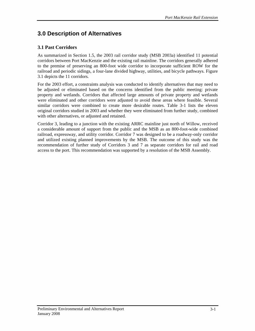
3.2 Alternatives under Evaluation Following the 2007 constraints analysis, the alternatives considered in 2003 were re-evaluated to confirm that the findings from the 2003 report were still relevant, and that the conditions had not changed to make one or more of the alternatives previously eliminated more preferable. The 2003 corridors were also evaluated to ensure that there were no other alternatives that should be considered that had been overlooked in the earlier study.
Alternative corridors were developed based on reviewing the 2003 corridors, the constraints analysis, and engineering and environmental considerations described in Sections 1 and 4. Current alternatives are shown on Figure 3.1 with the alternatives considered in the 2003 study for comparison purposes. All the corridors start at Port MacKenzie at the south and connect to the existing mainline to the north. Each corridor is composed of a southern and northern segment with a possible connector tying the segments together. The southern segments run either east or west of the Point MacKenzie Agricultural Project. Just north of the agricultural area, there are three main northern segments – Willow, Houston, and Big Lake – with Houston having a north or south variant. Connectors link the north and south segments together to create eight possible alignment configurations, as listed below and depicted on Figure 3.2.
1. Mac West – Connection 1 – Willow. This alignment would be 44.8 miles long. It is one of the longest alignments and contains the segments farthest west.
2. Mac West – Connection 1 – Houston – Houston North. This alignment would be 35.1 miles long, is one of the shorter alignments, and is geographically one of the middle alignments.
3. Mac West – Connection 1 – Houston – Houston South. This alignment would be 34.5 miles, is one of the shorter alignments, and is geographically one of the middle alignments.
4. Mac West – Connection 2 – Big Lake. This alignment would be 35.8 miles. It includes the southern segment along the west side of the Point MacKenzie Agricultural Project and the most eastern north segment going towards Big Lake.
5. Mac East – Connection 3 – Willow. This alignment would be 45 miles and is the longest. It includes the southern segment along the east side of the Point MacKenzie Agricultural Project and the most western north segment going towards Willow.
PO RT M AC KE N Z I EDI S T RI CT
PO IN T
M AC KE N Z IE
AG R I CU LT UR A L
PR O J EC T
PARKS HWY.
PORT MACKENZIE RD.
KNIK-G
OOSE BAY R
D.
HOLLYWOOD RD.
W. SUSITNA PKWY.
BU
RM
A R
D.
W. LAKES BLVD.
AYRSHIRE AVE.
K N I K A R M
B igLa ke
RedShi r tLak e
Fl a tHor nLak e
Lit t
l e
Su s i tn
a
Ri v
e r
S us
i tn
a
R
ive r
WILLOW FISHHOOK RD.
CowLak e H or s e sh oe
La ke
Pap oo seTw i n L ake s
KNIK
WILLOW
PALMER
WASILLA
HOUSTON
BIG LAKE THEBUTTE
ANCHORAGE
EAGLE RIVER
C H U G A C H S P
S U S I T N A F L A T S S G R
M A T A N U S K A V A L L E Y
M O O S E R A
N A N C Y L A K E
S R A
P A L M E R H A Y
F L A T S S G R
A L E X A N D E R
C R E E K
R E C R I V E R
G O O S E B A Y
S G R
LITTLE SUSITNA
REC RIVER
K R O T O & M O O S E
C R E E K R E C R
W I L L O WM O U N T A I N
C H AHATCHER PASS
PUBLIC USE A
WILLOWCREEK
SRA
140
180
120
155
150
145
135
130
125
190
185
175
170165 160
Willow
Big Lake
Mac West
Houston
Mac East
Conn 3
Conn 2
HoustonNorth
Conn 1
HoustonSouth
ALTERNATIVES
LEGEND
This map represents a conceptual level of utility, detail, and accuracy. Theinformation displayed here is for planning purposes only. Base information shownconstitutes data from various federal, state, public, and private souces. These mapsare for review purposes only and are not intended for use in securing permits, designor for construction purposes.
E 0 3 6 Miles
Date: November 5, 2007Projection: Alaska State Plane Zone 4, NAD 83
Author: HDR Alaska, Inc.Sources: ADNR, ARRC, HDR Alaska, Inc.,
MSB GIS, TNH- Hanson, USGS.
A L A S K A
PROJECT AREA
Preliminary Alternatives*
Mac East
Mac West
Conn 1
Conn 2
Conn 3
Houston
Houston North
Houston South
Willow
Big Lake
ARRC Track
ARRC Milepost
Highway
Medium Rd.
Minor Rd.
Iditarod Trail
City Boundary
Park or Refuge
*These lines generally represent corridors which aresubject to further refinement.
Figure 3.2 ALTERNATIVES UNDER EVALUATION

Port MacKenzie Rail Extension
Preliminary Environmental and Alternatives Report January 2008
(This page intentionally left blank.)

Port MacKenzie Rail Extension
Preliminary Environmental and Alternatives Report January 2008
3-5
6. Mac East – Connection 3 – Houston – Houston North. This alignment would be 35.3 miles, is one of the shorter alignments, and is geographically one of the middle alignments.
7. Mac East – Connection 3 – Houston – Houston South. This alignment would be 34.7 miles long, is one of the shorter alignments, and is geographically one of the middle alignments.
8. Mac East – Big Lake. This alignment would be 31.8 miles long and is the shortest alignment. It includes the southern segment along the east side of the Point MacKenzie Agricultural Project and the most eastern north segment going towards Big Lake.
The alignments consist of a 200-foot wide ROW to allow for the track, periodic sidings, and a railroad maintenance access road. Additional engineering criteria used to develop the alignments are presented in Section 2.1. Conceptual-level plans have been developed for each of the alternatives. Plan sets are included in Volume 2.
3.2.1 South Segments Port MacKenzie Terminal Area
The Mac West and Mac East segments have a common point of beginning, which is slightly less than one mile northwest of the Port MacKenzie dock facility as seen in Figure 3.3. In the terminal area, for the first 2.7 miles, both east and west segments would follow the same alignment. For approximately one mile, the track would curve north on an approximate 0.5% descending grade around existing port district development and would serve as a switching lead, where cars or sections of cars should be moved or switched among the terminal yard sidings. The ARRC’s terminal yard at the Port would be located approximately between the first and third miles of the track, roughly parallel to and 150 feet south of the existing Port MacKenzie Road. The initial construction terminal would consist of the main track and two 8,000-foot siding tracks. Construction of a level terminal yard would require fills of approximately 10 to 25 feet deep. An insulated metal building, approximately 80-feet by 100-feet in size with a loading dock, would be constructed at the terminal site to facilitate rail line and equipment maintenance and train crew assignments. An existing MSB recreational trailhead near the end of the first mile of track would be relocated west of the terminal area. At approximately Milepost (MP) 2.7, the common Mac West and Mac East segments would separate.

Port MacKenzie Rail Extension
Preliminary Environmental and Alternatives Report January 2008 3-6
Figure 3.3 Mac East and Mac West Segments
Mac West
From MP 2.7, the Mac West segment would proceed northwesterly across relatively flat terrain towards the southwest corner of the Port MacKenzie Agricultural Project. The corridor continues west of the agricultural area traversing along the eastern boundary of Susitna Flats SGR. Minimal fill would be needed to elevate the track structure above the gently rising and falling terrain.
Mac East
From MP 2.7, the Mac East segment turns northward, gaining elevation on a 0.4% grade along the side of a ridge along the east side of the agricultural area. Near ME MP 4.7 the segment crosses a ravine that would require approximately 25 feet of fill, and then curves to the northeast along the top of another ridge. North of MP 6, the segment approximately follows the alignment of Port MacKenzie Road, offset 200 feet or more to the west. The track continues along undulating terrain before reaching the junction of the Big Lake segment or Connector 3 segment.

Port MacKenzie Rail Extension
Preliminary Environmental and Alternatives Report January 2008
3-7
3.2.2 Connectors Three connectors were developed to transition from the south segments to the north segments (Figure 3.4).
Figure 3.4 Connection Segments
Connector 1
This 4.1 mile segment is used to connect Mac West to the Willow or Houston segments. From Mac West, this segment would continue northward, with a slight descending grade, skirting the eastern boundary of the Susitna Flats SGR on level terrain. The segment crosses a tributary of the Little Susitna River. Approaches to the tributary stream along this alignment would require substantial fills approaching 45 feet in height. The final mile of the segment ascends at 0.4% grade with minimal cut and fill.
Connector 2
This 3.7 mile segment would connect Mac West to the Big Lake segment. At the northwestern end of the agricultural area, this segment shifts completely eastward, and travels along the southern boundary of the Point MacKenzie Correctional Farm. This segment requires a minimal amount of fill and is elevated slightly above the gently rising terrain.

Port MacKenzie Rail Extension
Preliminary Environmental and Alternatives Report January 2008 3-8
Connector 3
This 4.5 mile segment is used to connect Mac East to the Willow or Houston segments. At the northeastern end of the agricultural area, the alignment shifts northwestward and crosses two roads. The segment would require minor cuts and occasional fills up to approximately 25 feet high to descend the rolling terrain on a 0.5% grade. The segment goes north of My Lake, crossing an adjacent ravine that would require fills approximately 45 feet in height. The remaining mile of the segment is nearly level.
3.2.3 North Segments Willow
From Connector 1 or 3, the Willow segment (Figure 3.5) descends on a 0.3% grade over the first mile, crossing the Little Susitna River with a bridge approximately 55 feet above the water. There are two conceptual options for bridge configurations (Figures 3.6 and 3.7). Over the next seven miles, the segment continues generally north, ascending on grades ranging up to 0.5% through rolling terrain that would require cuts and fills of up to approximately 35 feet. Fish Creek, the outlet for Red Shirt and Cow lakes, would be crossed with a bridge approximately 90 feet above the water. The segment would then proceed north, generally following the west facing slope of a glacial moraine that is located west of Red Shirt Lake. It continues northward staying west of the Nancy Lake SRA, and then descends off the glacial moraine. The segment would cross the outlet for Vera Lake, continue along rolling terrain requiring minor cuts and fills, and cross Willow Landing Road. The segment then crosses Willow Creek approximately 55 feet above the water and continues through the Willow Creek SRA. After crossing the Willow Creek valley, the segment curves to the east as it approaches the Parks Highway. The alignment would be grade-separated with the Parks Highway (road over railroad as conceptually depicted in Figure 3.9) before connecting to the existing mainline near existing ARRC MP 188.9. The alignment crosses a number of trails, including the Iron Dog Trail, the West Gateway Trails, the Nancy Lake-Susitna Trail, the Knik-Susitna Trail, the Crooked Lake Trail, and the INHT.

Port MacKenzie Rail Extension
Preliminary Environmental and Alternatives Report January 2008
3-9
Figure 3.5 Willow Segment

Port MacKenzie Rail Extension
Preliminary Environmental and Alternatives Report January 2008 3-10
Houston
From Connector 1 or 3, this segment proceeds northeastwardly, traveling through slightly undulating terrain with areas of marsh (Figure 3.6). The segment passes between the Papoose Twins Lakes and Crooked Lake, traversing an area of hilly terrain that would require fills of approximately 30 feet and cuts approximately 35 to 75 feet deep. The remaining four miles of the segment are located in a gradually rising marshy area to a point near Muleshoe Lake and Little Horseshoe Lake where it would break into two variant of options: Houston North and Houston South. Three anadromous streams are crossed. Several trails are crossed, including the INHT, the Knik-Susitna Trail, the Iron Dog Trail, and the Muleshoe Trail.
Figure 3.6 Houston Segment

Port MacKenzie Rail Extension
Preliminary Environmental and Alternatives Report January 2008
3-11
Houston North Variant
Beginning between Muleshoe Lake and Little Horseshoe Lake, this variant of the alignment would traverse northward, crossing over the Castle Mountain Fault (Figure 3.7). This alignment would cross the Cow Lake Trail, which is part of the Houston Lake Loop Trail. The segment enters the Little Susitna Recreation River, and then crosses the Little Susitna River. The segment continues north on rolling terrain that would require two approximately 30 foot cuts, then passes between Little Houston Lake and Tiger Lake, descending gradually to the lower terrain adjacent to Lake Creek. The alignment ties in to the existing mainline near existing ARRC MP 179.3 without crossing the Parks Highway.
Houston South Variant
Also beginning between Muleshoe Lake and Little Horseshoe Lake, this proposed variant would traverse northeasterly, passing just west of Pear Lake (Figure 3.7). The segment traverses several gravel ridges that run parallel to the lakes in this area. The alignment crosses a number of trails including the Muleshoe Trail (crossed twice), Connecting Trail #2, the Houston Lake Loop Trail, and the Houston Power Line Trail. The alignment ties into the existing mainline near MP 174.0 without crossing the Parks Highway. The junction would be in the immediate vicinity of the Castle Mountain Fault.
Figure 3.7 Houston North and South Segment

Port MacKenzie Rail Extension
Preliminary Environmental and Alternatives Report January 2008 3-12
Big Lake
The southern end of the Big Lake segment begins from Mac West via Connector 2 or directly from Mac East. At the northeast corner of the agricultural area, this segment runs northeast for approximately 3 miles, crossing Burma Road and contouring around lower terrain to the southeast (Figure 3.8). The segment continues on rolling terrain towards Goose Creek. This segment continues down the north face of a ridge on a curving alignment, passing north of a residential area near Goose Creek Road. The segment continues along rolling terrain, crossing over Goose Creek, Fish Creek, Lucille Creek and tributaries of Lucille Creek, and Little Meadow Creek. From Burma Road to Big Lake Road the alignment would require cuts of up to approximately 60 feet and fills up to 40 feet to maintain a grade at or below 0.5%. The Big Lake Road Crossing would be grade-separated, rail above road. The segment continues northward through a residential area before crossing under the Parks Highway. Hawk Road, the connection from the Parks Highway to Houston Middle and High Schools, would be realigned away from the grade separation. The Big Lake segment connects with the existing main line near existing ARRC MP 170.3 in a marshy area surrounding a creek that feeds into Long Lake.
This alignment has many anadromous stream, road, and trail crossings. There are 10 anadromous stream crossings including the four named crossings. Some of the trail crossings include Knik-Susitna, Herning, Three Mile, and the INHT. The Aurora Dog Mushing trails are crossed several times, and several trails along roads are also crossed, including Hollywood Road, Big Lake Road, and Burma Road. The alignment also goes through two MSB proposed wetland banks located south of Big Lake.
Figure 3.8 Big Lake Segment

Port MacKenzie Rail Extension
Preliminary Environmental and Alternatives Report January 2008
3-13
3.3 No Action Alternative Additionally, consideration of the No Action (or “No Build”) Alternative is required under NEPA guidance as a benchmark for comparison of the potential environmental effects of the various build alternatives. The No Action Alternative would not change the existing access to Port MacKenzie, which is a two-lane road from Wasilla. Goods and materials would continue to move between Interior Alaska and the port by truck. The No Action Alternative will be considered during preparation of the environmental document by the third party contractor under STB direction. The No Action Alternative is not considered further in this report.
3.4 Construction Construction of the selected alternative would follow a sequence that begins with a survey of the clearing limits and final track centerline, followed by site clearing and grubbing, development of staging areas, embankment construction, track and structure construction, site cleanup, and reclamation. The typical design plan involves construction of a roadbed (subgrade) to accommodate a new track along the described alignment. A cross-sectional view of the roadbed is discussed in Section 2.1. The actual footprint of the fill placement, or excavation cut, would be a function of the existing topography and desired design grade of the roadbed. The minimum footprint width at the top of the subgrade would be 52 feet.
The most time-consuming construction activity would be the creation of the subgrade for the new track, support structures, and ancillary facilities. Proposed construction would consist of placing fill material, and/or removing existing material, to facilitate the proposed design grade. The proposed route would be a typical 100 feet of ROW designated at each side of the proposed track centerline location. It is ARRC’s intent to utilize the proposed route and accompanying ROW for all activities consistent with the existing uses of their current ROW. The proposed ROW would be larger in areas where fill slopes or excavation cut slopes extend outside of the 200-foot wide ROW cross-section. In these areas, the ROW boundary would encompass the toe and top of the slope for all cut and fill locations with an additional 20 foot buffer to facilitate construction and maintenance activities. The construction limits would be the boundary for construction-related activities associated with the railroad extension. The construction limits would be defined as the edge of the cut or fill plus an additional 20 feet to facilitate construction. Existing undeveloped areas outside the construction limits would not be directly impacted from construction of this project. Furthermore, only the necessary area required for construction and construction activities within the ROW would be impacted during the construction process. New access roads and staging areas would likely be required along the alignment. Previously disturbed areas would be utilized for these activities to the greatest extent feasible.
Clearing and Grubbing
Following the survey of construction limits, the projected footprint would be cleared and grubbed. Clearing would be completed to the edge of the construction limits; however, grubbing is not anticipated outside the described footprint. Clearing involves felling and removing trees and undergrowth from the construction area. Grubbing would involve the removal of roots and other vegetation within the same area. These tasks would be accomplished using bulldozers, loaders, excavators, and scrapers. If the natural ground in these areas is highly compressible or otherwise unsuitable, then soil excavation may be required. Organic soil and herbaceous vegetation removed for roadbed construction would be stored on-site for application to finished slopes, to facilitate re-vegetation and provide erosion control, or would be removed from the area and disposed of in an acceptable manner.
Port MacKenzie Rail Extension
Preliminary Environmental and Alternatives Report January 2008 3-14
Grading
Once clearing and grubbing are completed, excavation and fill activities would begin. Excavation and fill would be accomplished utilizing bulldozers, excavators, loaders, dump trucks, and scrapers. To the extent practicable, the design profile grade would be adjusted to balance cut and fill quantities. If the project requires additional fill, it would be generated from borrow sources within the ROW or off-site. The transport of cut material would be completed using dump trucks and/or scrapers at the cut site along the proposed route to the closest designated fill location. At fill locations, the soil material would be spread out in thin layers and compacted prior to the application of successive soil layers. Culvert pipes would be placed in areas requiring drainage from one side of the fill to the other. Should the project create excess fill material, it would be removed from the site, transported and deposited in appropriate locations.
To the extent possible, the construction ROW would be used as a haul route to transport fill. When this is not feasible, existing paved or unpaved roads would be enhanced as necessary and utilized as alternate haul routes. These roads would be restored to pre-construction conditions subsequent to project completion. Heavy equipment travel during construction would be limited to existing roads and the proposed and existing ROW. Additional access roads are not anticipated for this project based on the conceptual engineering information; however, it is possible that new roads may be necessary in certain areas to shorten haul distances for fill or track material once final engineering for the selected route is completed.
Culverts, Bridges, and Roads
Numerous culverts would be installed and bridges would be constructed for the selected alignment. These structures would be installed concurrent with embankment construction. Some of the alignment alternatives have locations where established roads cross the railroad tracks. These crossings would become either grade crossings or grade separations as discussed in Section 4.4.1. Egress across proposed crossings would be maintained during construction and operation of the selected alignment.
Embankment and Track
When the subgrade is near the desired finished elevation, a road grader would be utilized to provide a crown at the center of the subgrade section. A slope at the top surface of the subgrade would direct drainage to a ditch line on both sides of the proposed roadbed. Once the subgrade is constructed, crushed rock would be placed atop the finished subgrade to form up to a typical 12-inch thick layer based upon final engineering; referred to as the sub-ballast layer. This sub-ballast layer provides structural support as well as drainage for the ballast section on top of it, and distributes the load more uniformly over the subgrade. The side slopes of the cut and fill slopes along the new alignment would have native seed or other appropriate stabilization applied.
Following placement and compaction of the sub-ballast, the new track would be started from a tie-in location at the existing track alignment. Ties and rail would be placed with conventional construction and track-mounted equipment in successive application, until the track is completely from one end of the alignment to the other. Once the track is installed for a certain distance, ballast trains would be routed over the loose track to place crushed rock ballast. Then the track would be adjusted to final grade and alignment using a tamper. This rail-mounted machine is designed to compact the ballast under the ties and, thus, adjust the elevation and horizontal location of the rails. Several cycles of ballast dumping and tamping would be required to lift the track to the design elevation with the proper amount of ballast under the ties. The ballast serves to hold the ties in place and distribute the load from the track to the sub-ballast and subgrade. Additional ballast material would be placed and compacted on the outside edge of the ties to hold
Port MacKenzie Rail Extension
Preliminary Environmental and Alternatives Report January 2008
3-15
the track in alignment. The ballast placing and tamping operation would follow the placement of track along the alignment.
Construction Materials
Materials such as ballast, ties, rail, and bridge beams represent the bulk of items that are not available in the local area and must be imported to complete the project. The majority of these items are expected to be transported to the site via ship and rail from out of state due to their weight and bulk. Materials such as ballast would be available from in-state sources.
Construction Crew, Equipment, and Schedule
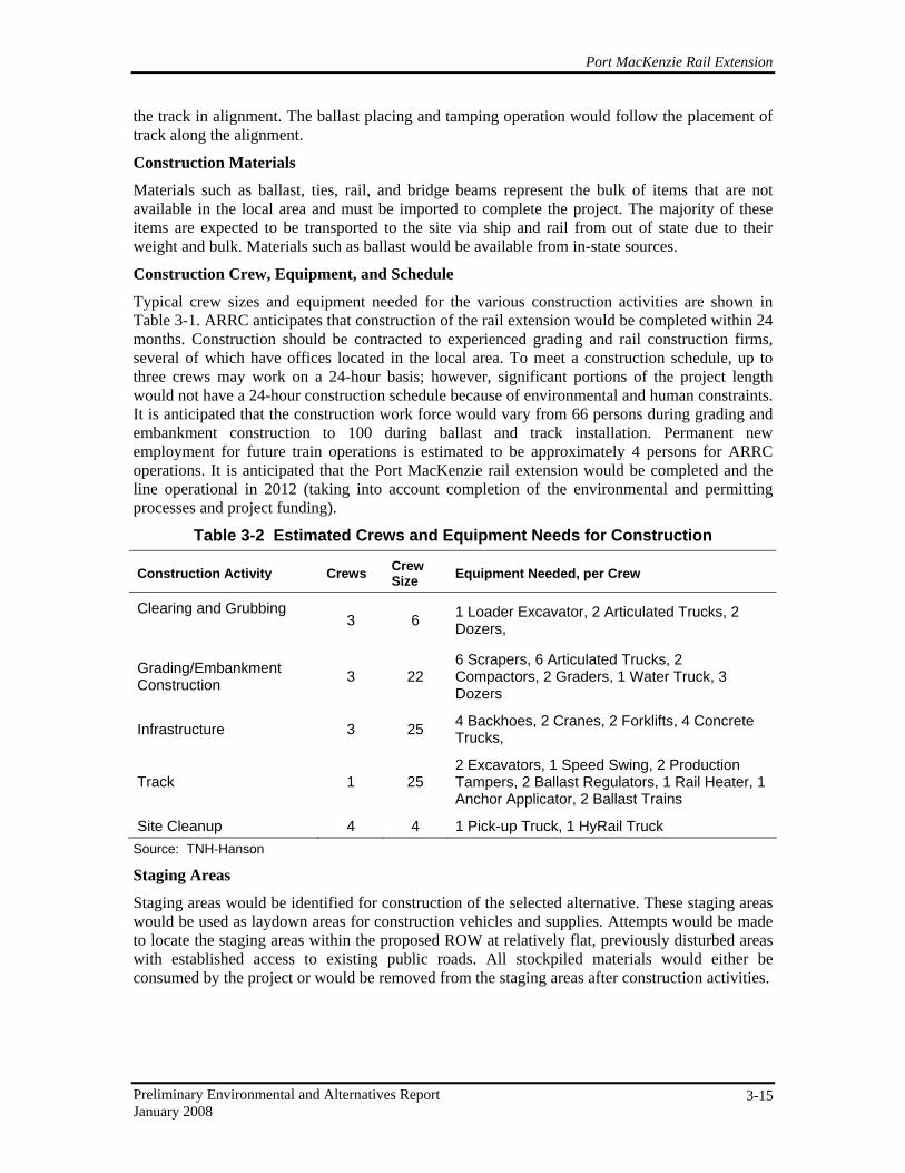
Typical crew sizes and equipment needed for the various construction activities are shown in Table 3-1. ARRC anticipates that construction of the rail extension would be completed within 24 months. Construction should be contracted to experienced grading and rail construction firms, several of which have offices located in the local area. To meet a construction schedule, up to three crews may work on a 24-hour basis; however, significant portions of the project length would not have a 24-hour construction schedule because of environmental and human constraints. It is anticipated that the construction work force would vary from 66 persons during grading and embankment construction to 100 during ballast and track installation. Permanent new employment for future train operations is estimated to be approximately 4 persons for ARRC operations. It is anticipated that the Port MacKenzie rail extension would be completed and the line operational in 2012 (taking into account completion of the environmental and permitting processes and project funding).
Table 3-2 Estimated Crews and Equipment Needs for Construction
Construction Activity Crews Crew Size Equipment Needed, per Crew
Clearing and Grubbing
3 6 1 Loader Excavator, 2 Articulated Trucks, 2 Dozers,
Grading/Embankment Construction 3 22
6 Scrapers, 6 Articulated Trucks, 2 Compactors, 2 Graders, 1 Water Truck, 3 Dozers
Infrastructure 3 25 4 Backhoes, 2 Cranes, 2 Forklifts, 4 Concrete Trucks,
Track 1 25 2 Excavators, 1 Speed Swing, 2 Production Tampers, 2 Ballast Regulators, 1 Rail Heater, 1 Anchor Applicator, 2 Ballast Trains
Site Cleanup 4 4 1 Pick-up Truck, 1 HyRail Truck Source: TNH-Hanson
Staging Areas
Staging areas would be identified for construction of the selected alternative. These staging areas would be used as laydown areas for construction vehicles and supplies. Attempts would be made to locate the staging areas within the proposed ROW at relatively flat, previously disturbed areas with established access to existing public roads. All stockpiled materials would either be consumed by the project or would be removed from the staging areas after construction activities.
Port MacKenzie Rail Extension
Preliminary Environmental and Alternatives Report January 2008 3-16
Maintenance
ARRC employees would maintain the new alignment on a regular basis. Examples of ongoing maintenance activities include track lining and surfacing, rail repair and replacement, embankment upkeep, and sight triangle vegetation clearance. A sight triangle is determined from where a vehicle would stop to evaluate the potential approach of a train at an at-grade crossing. Operations and maintenance problems would typically be addressed by small repair crews transported to the site along existing roads or along the adjacent tracks by use of rail-mounted vehicles. With the exception of emergency repair or derailment, maintenance operations are not expected to impact the project area.