Embed Size (px)
Citation preview

SAVE THESE INSTRUCTIONS
3-Pt. PTO Post Hole Digger
Owner’s Manual
WARNING: Read carefully and understand all ASSEMBLY AND OPERATION
INSTRUCTIONS before operating. Failure to follow the safety rules and other basic safety
precautions may result in serious personal injury.
Item # 51478, #51479, #51480

Page 2 of 22
Thank you very much for choosing a Nortrac™ product!
For future reference, please complete the owner’s record below:
Serial Number/Lot Date Code: ________________________________
Purchase Date: ____________________________________________
Save the receipt, warranty, and this manual. It is important that you read
the entire manual to become familiar with this product before you begin
using it.
This 3-Pt. PTO Post Hole Digger is designed for certain applications
only. Northern Tool & Equipment is not responsible for issues arising
from modification or improper use of this product such as an application
for which it was not designed. We strongly recommend that this product
not be modified and/or used for any application other than that for which
it was designed.
For technical questions, please call 1-800-222-5381.

Page 3 of 22
Table of Contents
Intended Use .......................................................................................................................................... 4
Technical Specifications ...................................................................................................................... 4
Important Safety Information ............................................................................................................... 4
Specific Operation Warnings ............................................................................................................... 5
Assembly Instructions .......................................................................................................................... 6
Before Each Use .................................................................................................................................. 12
Operating Instructions ........................................................................................................................ 13
After Each Use ..................................................................................................................................... 16
Maintenance ........................................................................................................................................ 17
Troubleshooting .................................................................................................................................. 18
Parts Diagram ...................................................................................................................................... 19
Parts List .............................................................................................................................................. 20
Replacement Parts .............................................................................................................................. 20
Limited Warranty ................................................................................................................................. 21
Page 4 of 22
Intended Use
The 6" Post Hole Digger (#51478), the 9" Post Hole Digger (#51479), and the 12" Post Hole Digger
(#51480) are PTO driven. The aggressive cast-steel, split-tip, auger rips through tough, compacted
soil. The strong, durable design includes a number of safety features. In addition to an integrated
safety shield, the Quik-Tach® threaded auger design is safer than a bolt-on auger, and the butterfly
flighting’s rounded edges make it safer than spiral flighting.
Technical Specifications
Property 51478 51479 51480
Drill Diameter 6" (152 mm) 9" (228 mm) 12" (304 mm)
Length of Auger 673 mm 914 mm 559 mm
Power Match 20-35 HP 20-40 HP 20-40 HP
PTO Speed 540 RPM 540 RPM 540 RPM
Gearbox Rate 3;1 3;1 3;1
Machine Weight 203 lb (92 kg) 243 lb (110 kg) 247 lb (112 kg)
Important Safety Information
Read and understand all instructions. Failure to follow all instructions may result in serious injury or
property damage.
The warnings, cautions, and instructions in this manual cannot cover all possible conditions or
situations that could occur. Exercise common sense and caution when using this tool. Always be
aware of the environment and ensure that the tool is used in a safe and responsible manner.
Do not allow persons to operate or assemble the product until they have read this manual and have
developed a thorough understanding of how it works.
Do not modify this product in any way. Unauthorized modification may impair the function and/or
safety and could affect the life of the product. There are specific applications for which the product
was designed.
Use the right tool for the job. DO NOT attempt to force small equipment to do the work of larger
industrial equipment. There are certain applications for which this equipment was designed. It will do
the job better and more safely at the capacity for which it was intended. DO NOT use this equipment
for a purpose for which it was not intended.
Industrial or commercial applications must follow OSHA requirements.
WORK AREA SAFETY
Inspect the work area before each use. Keep work area clean, dry, free of clutter, and well lit.
Cluttered, wet, or dark work areas can result in injury. Using the digger in confined work areas may
put you dangerously close to other cutting tools and rotating parts.
Do not allow the digger to come into contact with an electrical source. The tool is not insulated and
contact will cause electrical shock.
Page 5 of 22
Keep children and bystanders away from the work area while operating the tool. Do not allow children
to handle the digger.
Be aware of all power lines, electrical circuits, water pipes, and other mechanical hazards in your work
area. Some of these hazards may be hidden from your view and may cause personal injury and/or
property damage if contacted.
PERSONAL SAFETY
Stay alert, watch what you are doing, and use common sense when operating the digger. Do not use
the digger while you are tired or under the influence of drugs, alcohol, or medication. A moment of
inattention while operating the digger may result in serious personal injury.
Dress properly. Do not wear loose clothing, dangling objects, or jewelry. Keep your hair, clothing, and
gloves away from moving parts. Loose clothes, jewelry, or long hair can be caught in moving parts.
Wear the proper personal protective equipment when necessary. Use ANSI Z87.1 compliant safety
goggles (not safety glasses) with side shields, or when needed, a face shield. Use a dust mask in
dusty work conditions. Also use non-skid safety shoes, hardhat, gloves, dust collection systems, and
hearing protection when appropriate. This applies to all persons in the work area.
Do not overreach. Keep proper footing and balance at all times.
Do not use the tool when tired or under the influence of drugs, alcohol or medication.
Remove keys or wrenches before connecting the tool to an air supply, power supply, or turning on the
tool. A wrench or key that is left attached to a rotating part of the tool may cause personal injury.
Secure the work with clamps or a vise instead of your hand when practical. This safety precaution
allows for proper tool operation using both hands.
Digger USE AND CARE
Do not force the digger. Products do a better and safer job when used in the manner for which they
are designed. Plan your work, and use the correct product for the job.
Check for damaged parts before each use. Carefully check that the digger will operate properly and
perform its intended function. Replace damaged or worn parts immediately. Never operate the digger
with a damaged part.
Store the digger when it is not in use. Store it in a dry, secure place out of the reach of children.
Inspect the digger for good working condition prior to storage and before re-use.
Use only accessories that are recommended by the manufacturer for use with your digger.
Accessories that may be suitable for one product may create a risk of injury when used with another
tool. Never use an accessory that has a lower operating speed or operating pressure than the tool
itself.
Keep guards in place and in working order. Never operate the product without the guards in place.
Specific Operation Warnings
To prevent serious injury or death:

Page 6 of 22
Read and understand the Owner’s Manual before operating, servicing, or repairing equipment.
Stop the engine, remove the key, and set the brake before dismounting the tractor.
Operate from the tractor seat only.
DO NOT operate without guards in place and in good, working condition.
Never allow riders on equipment.
Stop the auger rotation before maneuvering, relocating, or transporting.
DO NOT operate when the auger is higher than 12 inches above ground level. Doing so may
cause the driveline to bind, resulting in equipment damage or operator injury.
Keep bystanders at least 50 feet away while operating.
DO NOT operate or transport on steep inclines.
DO NOT use if the implement is damaged. Repair it before continuing use.
Park and store on a hard, level surface.
Store out of reach of children. Not for use by or around children.
ENTANGLEMENT HAZARD
To prevent serious injury or death from rotating auger:
DO NOT use body weight to force the auger into the ground or locate the auger point when the
auger is turning.
Operate from the tractor seat only.
Keep hands, feet, clothing, and hair away from moving parts.
Keep away from the auger and cutting head when the engine is on.
ENTANGLEMENT HAZARD
To prevent serious injury or death from rotating driveline:
DO NOT operate without guards in place.
DO NOT operate higher than 540 RPM.
Keep hands, feet, clothing, and hair away from moving parts.
DO NOT operate without the driveline securely attached at both ends.
DO NOT operate without the driveline shields that turn freely on the driveline.
Assembly Instructions
Note: For safety, two people are recommended for the assembly of the digger.
1. Place palletized digger on level ground and cut the shipping bands.

Page 7 of 22
2. Attach the boom to the top link mounting bracket on the tractor using a top link pin and a linch
pin through the hole at the bottom of the boom.
3. Connect the A frame to the tractor’s 3-point lift arms using the 7/8” pull pins with nut and lock
washer.
4. Remove the top link pin from the A frame. Attach the A frame to the boom after selecting the
desired hole (for angle adjustment), using the 2-3/4” top link and the 7/16” linch pin.
5. Raise the 3-point lift arms high enough to allow room for the auger installation.
Page 8 of 22
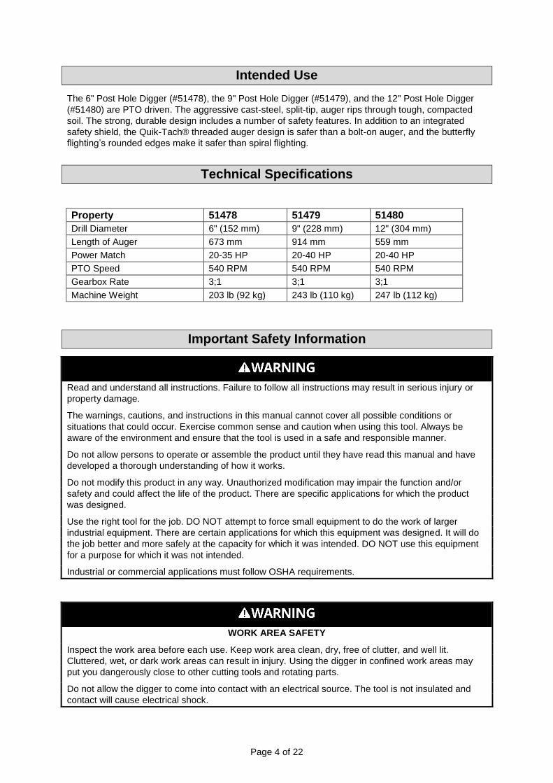
6. Using a 9/16” wrench, remove the shear bolt. Use a hex screwdriver to loosen the jam nut off
the screw enough to clear the internal bore of the PTO shaft.
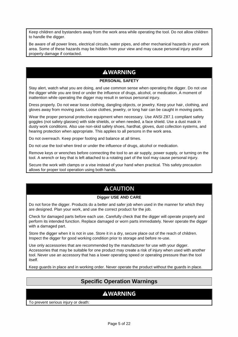
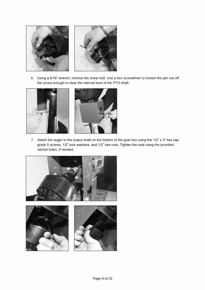
7. Attach the auger to the output shaft on the bottom of the gear box using the 1/2” x 3” hex cap
grade 5 screws, 1/2” lock washers, and 1/2” hex nuts. Tighten the nuts using the provided
ratchet holes, if needed.

Page 9 of 22
8. Attach the driveline to the gear box input shaft using the 5/16” grade 5 hex cap screw, the
5/16” lock washer, and the 5/16” NC hex nut. Tighten the hex nut. Insert the 1/4” x 3/8” set
screw from the hardware kit in the hole on the yoke that aligns with the 3/16” groove on the
gear box input shaft. Tighten.
Attention
The 3/8” hex cap screw provides shear protection. Use a grade 2 3” bolt (not provided) only to avoid
damage to the gear box or auger.
Important
The universal joint should be greased with a good grade chassis lube every week. At the beginning of
each season, grease the sliding drive shaft members with a moly grease. All diggers are equipped
with quick-detach universal joints on the PTO end for a 1-3/8” splined shaft.
9. Attach the tractor end of the driveline to the tractor PTO shaft. Push in the spring-loaded pin
in the splined yoke and slip it on the splined PTO shaft of the tractor. Release the pin and
push in until it locks securely in place. Note: It will be necessary to obtain a 1-1/8” to 1-3/8”
sleeve spline adapter if your tractor PTO shaft has a 1-1/8” spline.
10. Attach and secure both chains on the driveline to the boom.
Note: When the 7/8” diameter pull pins in the A frame are too small for the holes in the lift arms,
bushings should be used to obtain a proper fit.
Important:
The gearbox is shipped without lubricant. Refer to the next section before using the digger.
Always perform maintenance operations with the tractor engine off, the PTO drive disengaged, and
the auger point resting on the ground.

Page 10 of 22
Before Using the Digger
IMPORTANT
The digger was shipped without oil in the gearboxes. Oil must be added to the gearbox before
operating.
Note: Fill the gearbox using gear oil (type 80W-90 lubricant) and fill to the oil level plug. Check the
gear box every fifty hours of use to assure adequate lubrication.
Note: Check all nuts and bolts for tightness. Stabilizers should be kept tight to avoid the side sway of
the digger.
Adding and Changing Gearbox Oil
1. Using a 7/8” wrench, remove the 1/2” vented pipe plug located on front of the gearbox above the
PTO shaft.
2. Remove the check plug located at back of the gearbox.
3. Fill the front of the gearbox with gear oil until it begins to overflow from the check plug hole in
the rear.

Page 11 of 22
⚠CAUTION
DO NOT overfill the gearbox. This could cause damage to the oil seals and
can cause permanent damage to the gearbox (which is not covered under
warranty).
4. Replace and tighten the check plug.
5. Replace and tighten the 1/2” vented pipe plug and clean off any excess oil.
Attaching to the Tractor
Never stand between the tractor and the digger while backing up the tractor to the hitch.
Note: For safety, it’s recommended that two people attach the digger to the tractor.
1. Place the tractor and the digger on level ground and inspect for defects to make sure all
guards and shields are in place.
2. Set the digger in an upright position on the ground. While one person carefully balances the
digger, the other person attaches the boom to the top link mounting bracket and the A frame
to the lift arms on the tractor.
3. Raise the digger to allow enough room to install the auger. Attach the auger to the bottom of
the gearbox.
4. Attach the PTO driveline to the tractor and to the digger’s gearbox input shaft, and secure the
anti-rotation chains.
5. Determine if the PTO shaft needs to be shortened.
Page 12 of 22
Note: Due to the many variations in the tractor hitch points and distances between the equipment
gearbox input shaft and the tractor PTO output shafts, some combinations may require the PTO
shafts to be shortened, as described by the following steps.
6. Raise and lower the digger in order to locate the shortest distance between the equipment
gearbox, the input shaft, and the tractor PTO output shaft. With the digger is in the shortest
distance position, shut down the tractor, and secure the digger in position.
7. Pull apart the PTO shaft and attach the outer section to the tractor PTO output shaft.
Note: Be sure to pull on the PTO shaft section to ensure that the yoke is locked into place.
8. Place and hold the inner PTO shaft section next to the outer section and check to see if the
PTO shaft is too long. Each section should end approximately 3” short of reaching the u-joint
shield on the opposite section. If the shaft is too long, measure 3” back from each u-joint
shield and mark the other shaft section. Be sure to do this for both PTO shaft halves.
Note: Do not cut the PTO shaft sections at this time.
9. Raise the digger. Raise and lower the digger in order to locate the longest distance between
the equipment input shaft and the tractor PTO output shaft. With the digger in the longest
distance position, shut down the tractor and secure the digger in position.
10. As in step 5, hold the PTO shaft sections together and check for a minimum of 6” of overlap. If
the PTO shaft has been marked for cutting, the overlap is the distance measured between the
two marks. If the PTO shaft has less than a 6” overlap, do not use it. Contact your dealer for
a replacement.
Note: If the PTO shaft length is too long, refer to the Sizing the PTO Shaft section.
11. Apply any multi-purpose grease to the outside of the male (inner) PTO shaft section.
Assemble the PTO shaft and install on the digger and the tractor.
12. Pull on the tractor side of the PTO shaft yoke to be sure it has locked into place. Make certain
the PTO shaft shielding is in place and in good working condition.
13. The PTO shaft shield has a non-rotating design and must be secured prior to equipment use.
Attach the chains on the yoke shield to a fixed object on the tractor and the equipment. This
will prevent the PTO shield from rotating (see the top of page 10).
Before Each Use
Safety is a primary concern in the design and manufacturing of our product. Unfortunately, our efforts
to provide safe equipment can be wiped out by a single careless act of an operator or bystander.
In addition to the design and configuration of equipment, hazard control and accident prevention are
dependent upon the awareness, concern, prudence, and proper training of personnel involved in the
operation, transport, maintenance, and storage of this equipment.
It has been said, “The best safety device is an informed, careful operator.” We ask you to be that kind
of operator. It is the operator’s responsibility to read, understand, and follow all safety and operating
instructions in this manual. Accidents can be avoided.
Working with unfamiliar equipment can lead to careless injuries. Read this manual and your tractor’s
manual, before assembling or operating, to acquaint yourself with the machines. If this machine is
used by someone other than the owner, or is loaned or rented, it is the owner’s responsibility to make
certain that this manual be available to the operator prior to operating. All users must:

Page 13 of 22
1. Read and understand the Owner’s Manual.
2. Be instructed in safe and proper use.
Know your controls and how to stop the tractor, the engine, and the digger quickly in an emergency.
To understand how to do this, read this manual and your tractor’s manual.
Train all new personnel and review instructions frequently with existing workers. Be certain only a
properly trained and physically able person will operate the machinery. A person who has not read
and understood all operating and safety instructions is not qualified to operate the machine.
An untrained operator exposes himself and bystanders to possible serious injury or death. If the
elderly are assisting with farm work, their physical limitations need to be recognized and
accommodated.
Preparation
Never operate the tractor and digger until you have read and completely understood this manual, the
tractor Owner’s Manual, and each of the safety messages found on the safety signs on the tractor and
digger.
Personal protection equipment including hard hat, safety goggles, safety shoes, and gloves are
recommended during assembly, installation, operation, adjustment, maintenance, repairing, removal,
or movement of the implement. Do not allow long hair, loose fitting clothing, or jewelry to be around
equipment.
Prolonged exposure to loud noise may cause permanent hearing loss! Tractors with or without
diggers attached can often be noisy enough to cause permanent, partial hearing loss. We recommend
that you wear hearing protection on a full time basis if the noise in the operator’s position exceeds 65
dB. Noise over 65 dB on a long-term basis can cause severe hearing loss. Long term noise over 65
dB adjacent to the operator, may cause permanent, and total hearing loss.
Note: Hearing loss from loud noise (tractors, chain saws, radios, and other such sources close to the
ear) is cumulative over a lifetime, without hope of natural recovery.
Operate the digger only with a tractor equipped with an approved Roll Over Protection System
(ROPS). Always wear your seat belt. Serious injury or even death could result from falling off the
tractor — particularly during a turnover when the operator could be pinned under the ROPS or the
tractor.
Clear the digging area of stones, branches, or other debris that might be thrown or entangled in
the digger, causing injury or damage.
Operate only in daylight or good artificial light.
Ensure that the digger is properly mounted, adjusted, and in good operating condition.
Ensure that all safety shielding and safety signs are properly installed and in good condition.
Operating Instructions
Starting and Stopping
Check the tractor master shield over the PTO stub shaft. Make sure it is in good condition and
fastened securely to the tractor. Purchase a new shield if the old shield is damaged or missing.
All tractors that are not equipped with “live” PTO need to be equipped with an over-running PTO
clutch (available through most farm equipment stores).

Page 14 of 22
Note: The addition of an over-running PTO clutch may change the length of the PTO driveline
required. Pay extra attention to the instructions on the PTO Driveline installation. Be sure that the
driveline system guarding is adequate.
The digger’s operating power is supplied from the tractor PTO. Refer to your tractor manual for PTO
engagement and disengagement instructions. In the case of an emergency, know how to quickly stop
the tractor and the digger.
When engaging the PTO, the engine RPM should always be at idle speed. Once engaged and ready
to start digging, raise the PTO speed to 540 RPM and increase the speed as the auger drills deeper.
Hazards and Obstructions
The use of this equipment is subject to certain hazards that cannot be solely protected by the
mechanical means or product design. All operators of this equipment must read and understand this
entire manual, paying particular attention to safety and operating instructions prior to using. If there is
something in this manual that you do not understand, ask your supervisor or dealer to explain it to you.
Most accidents occur because of neglect or carelessness. Keep all helpers and bystanders at least
several hundred feet from an operating digger. Only properly trained people should operate this
machine.
When the machine is operated in populated areas where thrown objects could injure persons or
property, operation must be stopped when anyone comes within several hundred feet.
The majority of farm equipment accidents involve entanglement on the driveline, injury of bystanders
by the objects thrown by the rotating auger, and operators being knocked off the tractor by low
hanging limbs and being injured by the equipment. Accidents are most likely to occur with machines
that are loaned or rented to someone who has not read the Owner’s Manual and is not familiar with
the digger.
The digger is only designed for use on tractors with the PTO turning at 540 RPM.
Install and secure all guards and shields before starting or operating. The digger, driveline guards,
and tractor shields should be used and maintained in good working condition. They should be
inspected carefully, at least daily, for missing or broken chain links, shields, or guards. (Worn items
must be replaced at once to reduce the possibility of injury.)
Disengage the PTO shaft and place the transmission in neutral before attempting to start the engine.
Many varied objects, such as wire, cable, rope, or chains, can become entangled in the operating
parts of the digger. These items could then swing outside the housing at greater velocities than the
auger. Such a situation is extremely hazardous. Inspect the digging area for such objects before
digging. Remove any of these objects from the site.
Never allow the auger to contact such items. Never assume an area is clear. Always Check!
Always stop the tractor, disengage the PTO, set the brake, shut off the tractor engine, remove the
ignition key, lower the implement to the ground, and allow rotating pieces to come to a complete stop
before dismounting the tractor. Never leave the equipment unattended with the tractor running.
Never place hands or feet under the digger with the tractor engine running or before you are sure all
motion has ended. Stay clear of all moving parts.
Do not reach or place any part of your body under the equipment until it is properly secured.
Do not allow riders on the digger or the tractor at any time. There is no safe place for riders on this
equipment.

Page 15 of 22
Do not operate unless all personnel, livestock, and pets are several hundred feet away to prevent
injury by thrown objects.
Never operate the tractor and the digger under trees with low hanging limbs. Operators can be
knocked off the tractor and hit by equipment.
The rotating parts of this machine have been designed and tested for rugged use. However, they
could fail upon impact with heavy, solid objects such as steel guardrails and concrete abutment. Such
impact could cause the broken objects to be thrown outward at very high velocities. To reduce the
possibility of property damage, serious injury, or even death, never allow the auger to contact such
obstacles.
Stop the digger and the tractor immediately upon striking an obstruction. Turn the engine off, remove
the key, inspect the equipment, and repair any damage before resuming operation.
Maneuvering
Stay alert for uneven terrain, holes, rocks, roots, and other hidden hazards. Keep away from drop-offs
and hazards that could cause a roll over. Use extreme care and maintain minimum ground speed
when operating on hillsides, over rough ground, and close to ditches or fences. Be careful and slow
down when turning sharp corners and changing directions on slopes. Do not start or stop suddenly on
slopes. Avoid operation on steep slopes. In extremely uneven terrain, rear wheels weights, front
tractor weight, and/or tire ballasts should be used to improve stability.
Pass the digger diagonally through sharp dips and avoid sharp drops to prevent ‘hanging up’ the
tractor and the digger. Practice will improve your skills in maneuvering on rough terrain. Always travel
parallel to the slope, never cutting through. Always check the tractor manual for proper use on slopes.
When using this equipment, a minimum 20% of tractor and equipment weight must be on the tractor’s
front wheels. Without this weight, the tractor could tip over, causing personal injury or death. The
weight may be attained with a front-end loader, front wheel weights, ballast in the tires, or front tractor
weights. When attaining a minimum 20% of tractor and equipment weight on the front wheels, you
must not exceed the ROPS weight certification. Weigh the tractor and equipment. Do not guess or
estimate!
Transportation
Comply with state and local laws governing highway safety and movement of farm machinery on
public roads.
The use of flashing amber lights is acceptable in most localities. However, some localities prohibit
their use. Local laws should be checked for all lighting and marking requirements.
At all times, when driving the tractor and equipment on the road or highway under 20 MPH (32 KPH),
use flashing amber warning lights and a slow moving vehicle (SMV) identification emblem. Do not
exceed 20 MPH (32 KPH). Reduce speed on rough roads and surfaces.
Plan your route to avoid heavy traffic.
Always install transport locks, pins, or brackets before transporting.
Do not drink and drive.
Be a safe and courteous driver. Always yield to oncoming traffic in all situations, including narrow
bridges, intersections, etc. Watch for traffic when operating near or crossing roadways.
Turn curves or go up or down hills only at a low speed and at a gradual steering angle. Make certain
that a least 20% of the tractor’s weight is on the front wheels to maintain safe steerage. Slow down on
rough or uneven surface. Always check the tractor manual for proper use on slopes.

Page 16 of 22
Use extreme care and maintain minimum ground clearance when operating close to ditches or fences.
Be careful when turning sharp corners.
After Each Use
Note: For safety, it’s recommended that two people detach the digger.
⚠CAUTION
To prevent personal injury caused by unexpected movement:
1. Park the machine on a level surface.
2. Engage the tractor parking brake and/or place the transmission in
park.
3. Disengage the PTO.
4. Shut off the tractor’s engine and remove the key.
Detaching from the Tractor
1. Remove the PTO driveline from the tractor and the digger gearbox.
⚠WARNING
Shut off the tractor’s engine before detaching the PTO driveline. An
entanglement in a rotating driveline can cause serious injury or death.
2. Adjust the digger to allow room for the auger removal. Remove the auger from the bottom of
the gearbox.
3. Lower the boom by using the lift arms on the tractor. Detach the boom from the top link
mounting bracket and lift the arms.
4. Carefully lay the digger on the ground in a secure position.
Cutting the PTO Shaft to Length
Note: Be sure to cut equal lengths of each PTO shaft section.
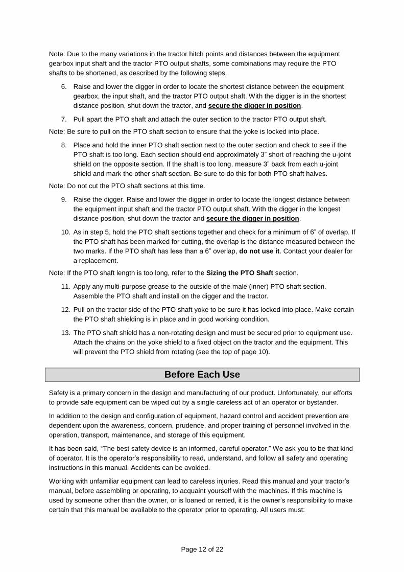
1. Clamp the end of the PTO shaft in a vice and cut off the shield where it’s marked (Figure A &
Figure B).
Page 17 of 22
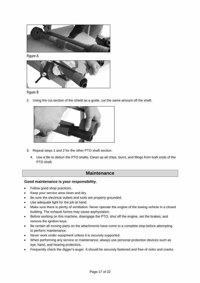
2. Using the cut section of the shield as a guide, cut the same amount off the shaft.
3. Repeat steps 1 and 2 for the other PTO shaft section.
4. Use a file to deburr the PTO shafts. Clean up all chips, burrs, and filings from both ends of the
PTO shaft.
Maintenance
Good maintenance is your responsibility.
Follow good shop practices.
Keep your service area clean and dry.
Be sure the electrical outlets and tools are properly grounded.
Use adequate light for the job at hand.
Make sure there is plenty of ventilation. Never operate the engine of the towing vehicle in a closed
building. The exhaust fumes may cause asphyxiation.
Before working on this machine, disengage the PTO, shut off the engine, set the brakes, and
remove the ignition keys.
Be certain all moving parts on the attachments have come to a complete stop before attempting
to perform maintenance.
Never work under equipment unless it is securely supported.
When performing any service or maintenance, always use personal protection devices such as
eye, hand, and hearing protectors.
Frequently check the digger’s auger. It should be securely fastened and free of nicks and cracks.

Page 18 of 22
Periodically tighten all bolts, nuts, and screws and check that all cotter pins are properly installed
to ensure the unit is in safe condition.
When completing a maintenance or service function, make sure all safety shields and devices are
installed before placing the unit in service.
After servicing, be sure all tools, parts, and service equipment are removed from the digger.
Do not allow debris, grease, or oil, to build up on the digger.
When replacement parts are necessary for periodic maintenance and servicing, genuine factory
replacement parts must be used to restore your equipment to original specifications.
The manufacturer will not be responsible for injuries or damages caused by the use of
unapproved parts and/or accessories.
A fire extinguisher and a first aid kit should be kept readily accessible while performing
maintenance on this equipment.
Troubleshooting
Always perform maintenance operations with the tractor engine off, the PTO drive disengaged, and
the auger point resting on the ground.
1. To remove the auger from the gear box output shaft, take out the two (2) 1/2” x 3-1/2” hex cap
screws.
2. To remove the drive shaft from the gear box input shaft, take out the shear pin bolt and the
1/4” set screw.
3. Check the oil level after every fifty hours of use. Use 80W- 90 lubricant and fill to the oil level
plug. All replacement lubricants should be of this type.
4. The universal joints should be greased with a good grade chassis lube every week. At the
beginning of each season, grease the sliding drive shaft members with moly grease.

Page 19 of 22
Parts Diagram
Page 20 of 22
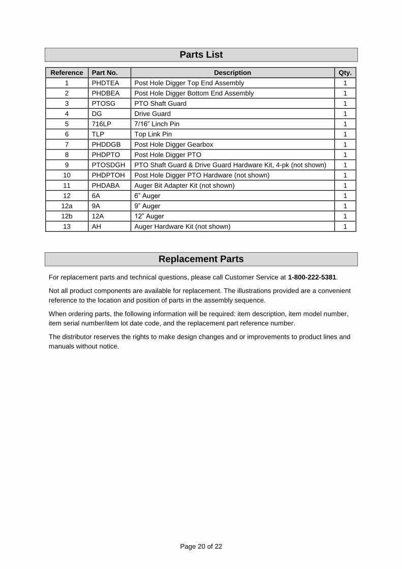
Parts List
Reference Part No. Description Qty.
1 PHDTEA Post Hole Digger Top End Assembly 1
2 PHDBEA Post Hole Digger Bottom End Assembly 1
3 PTOSG PTO Shaft Guard 1
4 DG Drive Guard 1
5 716LP 7/16” Linch Pin 1
6 TLP Top Link Pin 1
7 PHDDGB Post Hole Digger Gearbox 1
8 PHDPTO Post Hole Digger PTO 1
9 PTOSDGH PTO Shaft Guard & Drive Guard Hardware Kit, 4-pk (not shown) 1
10 PHDPTOH Post Hole Digger PTO Hardware (not shown) 1
11 PHDABA Auger Bit Adapter Kit (not shown) 1
12 6A 6” Auger 1
12a 9A 9” Auger 1
12b 12A 12” Auger 1
13 AH Auger Hardware Kit (not shown) 1
Replacement Parts
For replacement parts and technical questions, please call Customer Service at 1-800-222-5381.
Not all product components are available for replacement. The illustrations provided are a convenient
reference to the location and position of parts in the assembly sequence.
When ordering parts, the following information will be required: item description, item model number,
item serial number/item lot date code, and the replacement part reference number.
The distributor reserves the rights to make design changes and or improvements to product lines and
manuals without notice.

Page 21 of 22
Limited Warranty
Northern Tool and Equipment Company, Inc. ("We'' or '"Us'') warrants to the original purchaser only
("You'' or “Your”) that the Nortrac product purchased will be free from material defects in both
materials and workmanship, normal wear and tear excepted, for a period of one year from date of
purchase. The foregoing warranty is valid only if the installation and use of the product is strictly in
accordance with product instructions. There are no other warranties, express or implied, including the
warranty of merchantability or fitness for a particular purpose. If the product does not comply with this
limited warranty, Your sole and exclusive remedy is that We will, at our sole option and within a
commercially reasonable time, either replace the product or product component without charge to You
or refund the purchase price (less shipping). This limited warranty is not transferable.
Limitations on the Warranty
This limited warranty does not cover: (a) normal wear and tear; (b) damage through abuse, neglect,
misuse, or as a result of any accident or in any other manner; (c) damage from misapplication,
overloading, or improper installation; (d) improper maintenance and repair; and (e) product alteration
in any manner by anyone other than Us, with the sole exception of alterations made pursuant to
product instructions and in a workmanlike manner.
Obligations of Purchaser
You must retain Your product purchase receipt to verify date of purchase and that You are the original
purchaser. To make a warranty claim, contact Us at 1-800-222-5381, identify the product by make
and model number, and follow the claim instructions that will be provided. The product and the
purchase receipt must be provided to Us in order to process Your warranty claim. Any returned
product that is replaced or refunded by Us becomes our property. You will be responsible for return
shipping costs or costs related to Your return visit to a retail store.
Remedy Limits
Product replacement or a refund of the purchase price is Your sole remedy under this limited warranty
or any other warranty related to the product. We shall not be liable for: service or labor charges or
damage to Your property incurred in removing or replacing the product; any damages, including,
without limitation, damages to tangible personal property or personal injury, related to Your improper
use, installation, or maintenance of the product or product component; or any indirect, incidental or
consequential damages of any kind for any reason.
Assumption of Risk
You acknowledge and agree that any use of the product for any purpose other than the specified
use(s) stated in the product instructions is at Your own risk.
Governing Law
This limited warranty gives You specific legal rights, and You also may have other rights which vary
from state to state. Some states do not allow limitations or exclusions on implied warranties or
incidental or consequential damages, so the above limitations may not apply to You. This limited
warranty is governed by the laws of the State of Minnesota, without regard to rules pertaining to
conflicts of law. The state courts located in Dakota County, Minnesota shall have exclusive jurisdiction
for any disputes relating to this warranty.

Page 22 of 22
Distributed by:
Northern Tool & Equipment Company, Inc.
Burnsville, Minnesota 55306
www.northerntool.com
Made in China