Embed Size (px)
Citation preview

OP
ER
AT
OR
'S M
AN
UA
LPOST HOLE DIGGERM
AN
1034
(R
ev. 3
/31/
2017
)
3-Point MountedTPD25 - General Purpose for 15-25 hp Tractors
with Limited Category 1 or Category 0 Hitch
TPD35 - Standard-Duty for 20-35 hp Tractorswith Category 1 or Category 2 Hitch
TPD65 - Heavy-Duty for 25-65 hp Tractorswith Category 1 or Category 2 Hitch
TPD95 - Heavy-Duty for 35-95 hp Tractorswith Category 1 or Category 2 Hitch
2 Introduction Gen’l (Rev. 2/25/2016)
TO THE DEALER:
Assembly and proper installation of this product is the responsibility of the Woods® dealer. Read manual instructionsand safety rules. Make sure all items on the Dealer’s Pre-Delivery and Delivery Check Lists in the Operator’s Manualare completed before releasing equipment to the owner.
The dealer must complete the online Product Registration form at the Woods Dealer Website which certifies thatall Dealer Check List items have been completed. Dealers can register all Woods product atdealer.WoodsEquipment.com under Product Registration.
Failure to register the product does not diminish customer’s warranty rights.
TO THE OWNER:
Read this manual before operating your Woods equipment. The information presented will prepare you to do a better andsafer job. Keep this manual handy for ready reference. Require all operators to read this manual carefully and becomeacquainted with all adjustment and operating procedures before attempting to operate. Replacement manuals can beobtained from your dealer. To locate your nearest dealer, check the Dealer Locator at www.WoodsEquipment.com, or inthe United States and Canada call 1-800-319-6637.
The equipment you have purchased has been carefully engineered and manufactured to provide dependable andsatisfactory use. Like all mechanical products, it will require cleaning and upkeep. Lubricate the unit as specified.Observe all safety information in this manual and safety decals on the equipment.
For service, your authorized Woods dealer has trained mechanics, genuine Woods service parts, and the necessarytools and equipment to handle all your needs.
Use only genuine Woods service parts. Substitute parts will void the warranty and may not meet standards required forsafe and satisfactory operation. Record the model number and serial number of your equipment in the spacesprovided:
Model: _______________________________ Date of Purchase: _____________________
Serial Number: (see Safety Decal section for location) ____________________________________
Provide this information to your dealer to obtain correct repair parts.
Throughout this manual, the term NOTICE is used to indicate that failure to observe can cause damage to equipment.The terms CAUTION, WARNING, and DANGER are used in conjunction with the Safety-Alert Symbol (a triangle withan exclamation mark) to indicate the degree of hazard for items of personal safety.

Introduction 3MAN1034 (2/28/2013)
TABLE OF CONTENTSINTRODUCTION . . . . . . . . . . . . . . . . . . . . . . . . . . . . . . . . . . . . . . . . . . . . . . 2
GENERAL INFORMATION . . . . . . . . . . . . . . . . . . . . . . . . . . . . . . . . . . . . . . 3
SPECIFICATIONS . . . . . . . . . . . . . . . . . . . . . . . . . . . . . . . . . . . . . . . . . . . . . 4
SAFETY RULES . . . . . . . . . . . . . . . . . . . . . . . . . . . . . . . . . . . . . . . . . . . . 5 - 7
SAFETY DECALS . . . . . . . . . . . . . . . . . . . . . . . . . . . . . . . . . . . . . . . . . . . 8 - 9
OPERATION . . . . . . . . . . . . . . . . . . . . . . . . . . . . . . . . . . . . . . . . . . . . . . . . 10
PRE-OPERATION CHECKLIST . . . . . . . . . . . . . . . . . . . . . . . . . . . . . . . . . 13
OWNER SERVICE . . . . . . . . . . . . . . . . . . . . . . . . . . . . . . . . . . . . . . . . . . . 14
TROUBLE SHOOTING . . . . . . . . . . . . . . . . . . . . . . . . . . . . . . . . . . . . . . . . 17
ASSEMBLY INSTRUCTIONS . . . . . . . . . . . . . . . . . . . . . . . . . . . . . . . . . . . 19
DEALER CHECK LIST . . . . . . . . . . . . . . . . . . . . . . . . . . . . . . . . . . . . . . . . 26
PARTS INDEX . . . . . . . . . . . . . . . . . . . . . . . . . . . . . . . . . . . . . . . . . . . . . . . 27
BOLT TORQUE CHART . . . . . . . . . . . . . . . . . . . . . . . . . . . . . . . . . . . . . . . 42
BOLT SIZE CHART & ABBREVIATIONS . . . . . . . . . . . . . . . . . . . . . . . . . . 43
PRODUCT WARRANTY . . . . . . . . . . . . . . . . . . . . . . . . . . . . . . . . . . . . . . . 44
REPLACEMENT PARTS WARRANTY . . . . . . . . . . . . INSIDE BACK COVER
GENERAL INFORMATION
■ Some illustrations in this manual show the dig-ger with safety shields removed to provide a betterview. The digger should never be operated withany safety shielding removed.
The purpose of this manual is to assist you in operatingand maintaining your post hole digger. Read it care-fully. It furnishes information and instructions that willhelp you achieve years of dependable performance.These instructions have been compiled from extensivefield experience and engineering data. Some informa-tion may be general in nature due to unknown and
varying operating conditions. However, through experi-ence and these instructions, you should be able todevelop procedures suitable to your particular situa-tion.
The illustrations and data used in this manual were cur-rent at the time of printing but, due to possible inlineproduction changes, your machine may vary slightly indetail. We reserve the right to redesign and change themachines as may be necessary without notification.
Throughout this manual, references are made to rightand left direction These are determined by standingbehind the equipment facing the direction of forwardtravel.
�������

4 Introduction MAN1034 (2/28/2013)
SPECIFICATIONS
Post Hole Digger Model TPD25 TPD35 TPD65 TPD95
3-Point Hitch CAT 1,Limited CAT1 or
CAT 0
CAT1 CAT1 or CAT2 CAT1 or CAT2
Tractor Horsepower 15 - 25 hp 20 - 35 hp 25 - 65 hp 35 - 95 hp
Tractor PTO 540 RPM 540 RPM 540 RPM 540 RPM
Approximate Weight 140 lbs 146 lbs 194 lbs 238 lbs
Driveline protection 5/16 x 2-1/2Grade 2
Shear Bolt
5/16 x 2-1/2Grade 2
Shear Bolt
5/16 x 2-1/2Grade 2
Shear Bolt
5/16 x 2-1/2Grade 2
Shear Bolt
Auger Length 36 inches(recommended)
48 inches(recommended)
48 inches(recommended)
48 inches(recommended)
Auger Points Cast Ductile Iron, Spiral Point, Replaceable
Cutting Teeth Alloy Steel, Hardened, Replaceable
Gearbox 540 RPM, Roller and Ball Bearings, Cast Iron Housing
Gearbox Lubrication SAE 90 Weight Gear Lube

Safety 5TPD SR (2/28/2013)
TRAINING Safety instructions are important! Read allattachment and power unit manuals; follow allsafety rules and safety decal information. (Replace-ment manuals and safety decals are available fromyour dealer. To locate your nearest dealer, checkthe Dealer Locator at www.WoodsEquipment.com,or in the United States and Canada call 1-800-319-6637.) Failure to follow instructions or safety rulescan result in serious injury or death.
If you do not understand any part of this manualand need assistance, see your dealer.
Know your controls and how to stop engine andattachment quickly in an emergency.
Operators must be instructed in and be capableof the safe operation of the equipment, its attach-ments, and all controls. Do not allow anyone tooperate this equipment without proper instruc-tions.
Keep hands and body away from pressurizedlines. Use paper or cardboard, not hands or otherbody parts to check for leaks. Wear safety goggles.Hydraulic fluid under pressure can easily penetrateskin and will cause serious injury or death.
Make sure that all operating and service person-nel know that if hydraulic fluid penetrates skin, itmust be surgically removed as soon as possible by
a doctor familiar with this form of injury or gan-grene, serious injury, or death will result. CON-TACT A PHYSICIAN IMMEDIATELY IF FLUIDENTERS SKIN OR EYES. DO NOT DELAY.
Never allow children or untrained persons tooperate equipment.
PREPARATION
Check that all hardware is properly installed.Always tighten to torque chart specificationsunless instructed otherwise in this manual.
Always wear relatively tight and belted clothingto avoid entanglement in moving parts. Wearsturdy, rough-soled work shoes and protectiveequipment for eyes, hair, hands, hearing, and head;and respirator or filter mask where appropriate.
Make sure attachment is properly secured,adjusted, and in good operating condition.
Make sure spring-activated locking pin or collarslides freely and is seated firmly in tractor PTOspline groove.
Connect PTO driveline directly to power unitPTO shaft. Never use adapter sleeves or adaptershafts. Adapters can cause driveline failures due toincorrect spline or incorrect operating length andcan result in personal injury or death.
Power unit must be equipped with ROPS orROPS cab and seat belt. Keep seat belt securelyfastened. Falling off power unit can result in deathfrom being run over or crushed. Keep foldableROPS system in “locked up” position at all times.
Make sure all safety decals are installed.Replace if damaged. (See Safety Decals section forlocation.)
Make sure shields and guards are properlyinstalled and in good condition. Replace if damaged.
Keep unit from swinging side-to-side by usingstabilizer bars, adjustable sway chains, or swayblocks on tractor lift arms. Adjust tightly for bestresults.
OPERATION
Do not allow bystanders in the area when oper-ating, attaching, removing, assembling, or servic-ing equipment.
Safety is a primary concern in the design andmanufacture of our products. Unfortunately, ourefforts to provide safe equipment can be wipedout by an operator’s single careless act.
In addition to the design and configuration ofequipment, hazard control and accident preven-tion are dependent upon the awareness, con-cern, judgement, and proper training ofpersonnel involved in the operation, transport,maintenance, and storage of equipment.
It has been said, “The best safety device is aninformed, careful operator.” We ask you to bethat kind of operator.
Si no lee Ingles, pida ayuda a alguien que si lo lea para que le
traduzca las medidas de seguridad.
LEA EL INSTRUCTIVO!!
SAFETY RULESATTENTION! BECOME ALERT! YOUR SAFETY IS INVOLVED!

6 Safety TPD SR (2/28/2013)
Consult local utilities before digging. Knowlocation and depth of all underground cables, pipe-lines, and other hazards in working area and avoidcontact.
Do not put digger into service unless augerpoint and all cutting edges are intact and in goodrepair.
Do not put digger into service unless all shieldsand guards are in place and in good condition.Replace if damaged.
Keep bystanders away from equipment.
Do not operate or transport equipment whileunder the influence of alcohol or drugs.
Operate only in daylight or good artificial light.
Never aim auger point with hands on auger,gearbox, boom or driveline. To place auger pointuse 3-point arms and handle.
Keep hands, feet, hair, and clothing away fromequipment while engine is running. Stay clear of allmoving parts.
Always comply with all state and local lightingand marking requirements.
Never allow riders on power unit or attachment.
Power unit must be equipped with ROPS orROPS cab and seat belt. Keep seat belt securelyfastened. Falling off power unit can result in deathfrom being run over or crushed. Keep foldableROPS system in “locked up” position at all times.
Always sit in power unit seat when operatingcontrols or starting engine. Securely fasten seatbelt, place transmission in neutral, engage brake,and ensure all other controls are disengagedbefore starting power unit engine.
When digging holes, always sit in operator seat.
To reduce rapid U-joint wear and driveline fail-ure, never lift auger over 12" from ground whenPTO is running.
Shift tractor transmission into park or neutraland set brakes before engaging PTO and digging.
Keep digger under control by running PTO atslowest speed possible (no faster than half-throttlein 540 rpm range).
Look down and to the rear and make sure areais clear before operating in reverse.
Use extreme care when working close to fences,ditches, other obstructions, or on hillsides.
Do not operate or transport on steep slopes.
When digging in rough ground or hilly terrain,place digger uphill from tractor. If digger is down-hill, tractor could tip when pulling auger from hole.
Do not stop, start, or change directions sud-denly on slopes.
Use extreme care and reduce ground speed onslopes and rough terrain.
When dislodging a stuck auger, disengage PTO,stop engine, remove key, disconnect PTO fromtractor, and turn auger backwards with a wrench.Remove and store wrench before starting engine.
Before performing any service or maintenance,lower digger to ground or block securely, turn offtractor engine, remove key, and disconnect drive-line from tractor PTO.
Never leave a running machine unattended.
Before leaving tractor seat, stop PTO, set brake,shut off engine, remove key, and let auger come toa full stop.
MAINTENANCE
Before performing any service or maintenance,lower digger to ground or block securely, turn offtractor engine, remove key, and disconnect drive-line from tractor PTO.
Never go underneath equipment (lowered to theground or raised) unless it is properly blocked andsecured. Never place any part of the body under-neath equipment or between moveable parts evenwhen the engine has been turned off. Hydraulicsystem leak down, hydraulic system failures,mechanical failures, or movement of control leverscan cause equipment to drop or rotate unexpect-edly and cause severe injury or death.
Service and maintenance work not covered inOWNER SERVICE must be done by a qualifieddealership. Special skills, tools, and safety proce-dures may be required. Failure to follow theseinstructions can result in serious injury or death.
When dislodging a stuck auger, disengage PTO,stop engine, remove key, disconnect PTO fromtractor, and turn auger backwards with a wrench.Remove and store wrench before starting engine.
SAFETY RULESATTENTION! BECOME ALERT! YOUR SAFETY IS INVOLVED!

Safety 7TPD SR (2/28/2013)
Use a suitable lifting device of sufficient capac-ity. Use adequate personnel to handle heavy com-ponents.
Do not modify or alter or permit anyone else tomodify or alter the equipment or any of its compo-nents in any way.
Never replace shear bolt or auger retaining boltwith a different length, or grade. Always use agrade 2 bolt as a replacement.
Always wear relatively tight and belted clothingto avoid getting caught in moving parts. Wearsturdy, rough-soled work shoes and protectiveequipment for eyes, hair, hands, hearing, and head;and respirator or filter mask where appropriate.
Do not allow bystanders in the area when oper-ating, attaching, removing, assembling, or servic-ing equipment.
Make sure attachment is properly secured,adjusted, and in good operating condition.
Never perform service or maintenance withengine running. Keep all persons away from operator controlarea while performing adjustments, service, ormaintenance.
Tighten all bolts, nuts, and screws to torquechart specifications. Check that all cotter pins areinstalled securely to ensure equipment is in a safecondition before putting unit into service.
Make sure all safety decals are installed.Replace if damaged. (See Safety Decals section forlocation.)
Make sure shields and guards are properlyinstalled and in good condition. Replace if damaged.
When lubricating telescoping PTO drives, keepfingers out of shield access slots to prevent injury.
TRANSPORTATION
Always comply with all state and local lightingand marking requirements.
Never allow riders on power unit or attachment.
Power unit must be equipped with ROPS orROPS cab and seat belt. Keep seat belt securelyfastened. Falling off power unit can result in deathfrom being run over or crushed. Keep foldableROPS system in “locked up” position at all times.
Do not operate PTO during transport.
Do not operate auxiliary hydraulics duringtransport.
Look down and to the rear and make sure areais clear before operating in reverse.
Do not stop, start, or change directions sud-denly on slopes.
Use extreme care and reduce ground speed onslopes and rough terrain.
Use additional caution and reduce speed whenunder adverse surface conditions, turning, or oninclines.
Do not operate or transport on steep slopes.
Do not operate or transport equipment whileunder the influence of alcohol or drugs.
A minimum 20% of tractor and equipmentweight must be on the tractor front wheels whenattachments are in transport position. Without thisweight, front tractor wheels could raise up result-ing in loss of steering. The weight may be attainedwith front wheel weights, ballast in tires or fronttractor weights. Weigh the tractor and equipment.Do not estimate.
Raise unit as high as possible for transport.
Reduce transport speed to avoid bouncing andbrief loss of steering control.
STORAGE
Block equipment securely for storage.
Keep children and bystanders away from stor-age area.
Do not climb or lean on equipment stored onstand.
SAFETY RULESATTENTION! BECOME ALERT! YOUR SAFETY IS INVOLVED!

8 Safety MAN1034 (2/28/2013)
BE CAREFUL!
Use a clean, damp cloth to clean safety decals. Avoid spraying too close to decals when using a pressure washer; high-pressure water can enter through very small scratches or under edges of decals causing them to peel or come off. Replacement safety decals can be ordered free from your Woods dealer, or in the United States and Canada call 1-800-319-6637.
1 - SERIAL NUMBER PLATE
2 - PN 1032569
4 - PN 1032571
5 - PN 18866
7 - PN 1886911 - PN 19924
SAFETY & INSTRUCTIONAL DECALSATTENTION! BECOME ALERT! YOUR SAFETY IS INVOLVED!
Replace Immediately If Damaged!
(Rev. 1/15/2015)

Safety 9MAN1034 (2/28/2013)
����� ������
�� �� � �����
�����
33347E
�����
�����
����� ������
�� �� � �����
10 - PN 33347Located under PTO shield
9 - PN 18869
12 - PN 1034504
3 - PN 1032568
6 - PN 1032570
8 - PN 1002941
SAFETY & INSTRUCTIONAL DECALSATTENTION! BECOME ALERT! YOUR SAFETY IS INVOLVED!
Replace Immediately If Damaged!
(Rev. 1/15/2015)

10 Operation MAN1034 (2/28/2013)
OPERATION
The operator is responsible for the safe operation ofthe equipment. The operator must be properly trained.Operators should be familiar with the equipment, thetractor, and all safety practices before starting opera-tion. Read the safety rules and safety decals on page 4to page 9.
Post hole diggers are designed for one-man operation.You must always dig holes while sitting in the tractorseat. It is the responsibility of the operator to seethat no one else is within twenty-five feet (25’) ofthe digger when it is operating. Accidents haveoccurred when more than one person is in the immedi-ate area of the operating equipment. Be sure no oneelse is near you when you operate this product.
Do not put digger into service unless all shieldsand guards are in place and in good condition.Replace if damaged.
Never aim auger point with hands on auger,gearbox, boom or driveline. To place auger pointuse 3-point arms and handle.
Do not shovel dirt away from a running auger.The shovel could be caught and thrown by auger.
Consult local utilities before working. Knowlocation of all underground cables, pipelines, over-head wires, and other hazards in working area andavoid contact.
When dislodging a stuck auger, disengage PTO,stop engine, remove key, disconnect PTO fromtractor, and turn auger backwards with a wrench.Remove and store wrench before starting engine.
Keep hands, feet, hair, and clothing away fromequipment while engine is running. Stay clear of allmoving parts.
Keep hands and body away from pressurizedlines. Use paper or cardboard, not hands or otherbody parts to check for leaks. Wear safety goggles.Hydraulic fluid under pressure can easily penetrateskin and will cause serious injury or death.
Make sure that all operating and service person-nel know that if hydraulic fluid penetrates skin, itmust be surgically removed as soon as possible bya doctor familiar with this form of injury or gan-grene, serious injury, or death will result. CON-TACT A PHYSICIAN IMMEDIATELY IF FLUIDENTERS SKIN OR EYES. DO NOT DELAY.
Do not put digger into service unless augerpoint and all cutting edges are intact and in goodrepair.
Keep bystanders away from equipment.
Shift tractor transmission into park or neutraland set brakes before engaging PTO and digging.
Keep digger under control by running PTO atslowest speed possible (no faster than half-throttlein 540 rpm range).
Always wear relatively tight and belted clothingto avoid getting caught in moving parts. Wearsturdy, rough-soled work shoes and protectiveequipment for eyes, hair, hands, hearing, and head;and respirator or filter mask where appropriate.
Tighten all bolts, nuts, and screws to torquechart specifications. Check that all cotter pins areinstalled securely to ensure equipment is in a safecondition before putting unit into service.
When digging holes, always sit in operator seat.
IMPORTANT Never exceed the recommended auger capacityof the post hole digger. The model TPD25 light-duty digger is designed for use with augers up to12-inch diameter. Use of an incorrect auger orauger extension can cause equipment damage,loss of operator control and personal injury.
PREPARATION
Thoroughly read and understand your Operator’s Man-uals.
Before beginning operation, clear area of objects thatwrap around the auger or might be thrown.
Contact local utility company to make certain there areno buried gas lines, electrical cables, etc., in the workarea.
Check for ditches, stumps, holes, or other obstaclesthat could cause the tractor to roll.
To dig properly, your digger must be able to raise orlower through the highest and lowest points of your liftarm travel without binding against the tractor frame.Check carefully BEFORE attaching the auger. If it doesbind, adjust the tractor 3-pt. linkage so that all move-ment is free.
������
�������
�������
CAUTION

Operation 11MAN1034 (2/28/2013)
Use stabilizer bars, adjustable sway chains, or swayblocks on your tractor lift arms to keep the post holedigger from swaying side to side. Adjust as tightly aspractical for best performance. Remove or place tractordrawbar in storage position.
IMPORTANT■ Post hole digger gearboxes are shipped with-out lubrication. Gearboxes must be serviced with90W gear lube before operation.
■ If PTO driveline interferes with swinging draw-bar, swing drawbar out of the way or remove.
OPERATING TECHNIQUE
Never aim auger point with hands on auger,gearbox, boom or driveline. To place auger pointuse 3-point arms and handle.
Do not shovel dirt away from a running auger.The shovel could be caught and thrown by auger.
IMPORTANT■ NEVER use body weight to help the auger pen-etrate the ground.
1. Position the tractor so that the auger point isplaced where the hole is to be dug.
2. Set tractor brakes. Shift transmission into park orneutral.
3. Do not allow anyone to stand behind, or to the sideof a rotating auger.
4. Lower auger point slowly to the ground with thePTO disengaged.
The point of the auger should be approximately 3" backof center of the gearbox. As the auger works into theground, this slight angle will straighten, due to the piv-oting action of the boom downward. If the auger has aside tilt, correct with the lift arm adjustment on the trac-tor hitch.
If the auger tilts too far forward or to the rear, it may benecessary to move the tractor slightly. Be careful not tobend the auger.
With the auger point lowered to the ground, set theengine speed to idle, then engage the PTO. Make surethe auger point is on the ground before engaging thePTO.
IMPORTANT■ Under no circumstances should the PTO be runin excess of 540 RPM.
As the auger penetrates the ground, lower the unitslowly with the 3-point lift arms. Do not let the auger
screw itself into the ground! Auger must dig with thedirt breaking up and being carried to the top by theauger flighting.
Figure 1. Operation
Dig the hole in small steps. Dig down several inches,then bring the auger up to let the soil clear. Repeat thisprocedure until the desired depth is reached. Thisallows better control of the auger and can prevent diffi-culties that could lead to an accident.
IMPORTANT■ Be careful when raising the auger as high asyour tractor’s 3-point lift arms can go. This can putthe PTO shaft universal joints at an extreme angleand cause damage to the PTO shaft! It is best toraise the auger just enough to clear the hole whenthe PTO is engaged.
■ It is recommended NOT to raise the auger morethan six (6) inches above the ground while it is run-ning. Once the hole is dug to the desired depthraise the auger while rotating to bring the dirt outof the hole.
To get a clean hole, it is sometimes best to lower theauger into the hole with the auger turning and then,when at the bottom, stop the rotation and raise theauger while not turning. This brings the dirt up with littleleft in the hole.
Disengage the PTO when traveling between holes.
In some types of soil it may be necessary to use the 3-point lift arms to prevent the auger from screwing itselfinto the ground.
When the ground is too tough to penetrate with yourcutting edges and point, sharpen or replace them andtry again. These are replaceable parts and must be ingood condition to penetrate. (An optional HydraulicDown Pressure Kit is available.)
�������

12 Operation MAN1034 (2/28/2013)
If you have difficulty penetrating hard ground, refer tothe Troubleshooting section in this manual for sugges-tions.
DOWN FORCE KIT OPERATION (OPTIONAL)
IMPORTANT■ Do not connect RETURN hose to a remote out-let. Remote outlet ports are blocked in the neutralposition and will damage the hydraulic cylinderwhen boom is raised.
1. Lower post hole digger using the 3-point arms andallow auger to dig.
2. If down force is required, slowly apply down forceusing the control lever for the remote outlet. Applyforce in small amounts.
3. Continue to lower the auger using the tractor 3-point lift arms as the auger digs.
4. Raise auger with the 3-point lift arms. Cylinder willretract when auger is raised out of the hole.
TRANSPORT
Do not operate PTO during transport.
The post hole digger auger is free-swinging, and careshould be taken while transporting the machine.
Be sure auger is completely retracted from the holebefore attempting to move the tractor.
DO NOT transport the post hole digger while the PTOis engaged as this could cause the universal joints ofthe PTO driveline into a sharp operating angle andcause failure of the driveline.
Pay particular close attention to the Safety Messagesregarding transport. Avoid unnecessary injuries andequipment damage by exercising cautious, conscien-tious travel procedures.
Attaching the implement to the tractor increases theoverall length of the working unit. Allow additionalclearance for the implement to swing when turning.
Raise the implement as high as possible for transport-ing.
LODGED AUGER
When dislodging a stuck auger, disengage PTO,stop engine, remove key, disconnect PTO fromtractor, and turn auger backwards with a wrench.Remove and store wrench before starting engine.
IMPORTANT■ Removing a lodged auger can be dangerouswork. Be careful.
1. If the auger gets stuck in wet clay, stones or roots,disengage the PTO immediately and turn off theengine.
2. Turn the auger backwards several turns with alarge pipe wrench. Then attempt to raise the augerwith the 3-point lift arms. Extreme rocking or liftingloads while trying to clear auger can cause auger,gearbox, or boom failure.
NOTE: Do not attempt to raise the auger whileturning it with a wrench or with a wrench attachedto the auger. You could be injured if the PTO wasaccidently engaged or the 3-point lift arms sud-denly raised the auger.
3. Remove and store wrench before starting engine.
Figure 2. Dislodge Auger
�������
�������
Operation 13MAN1034 (2/28/2013)
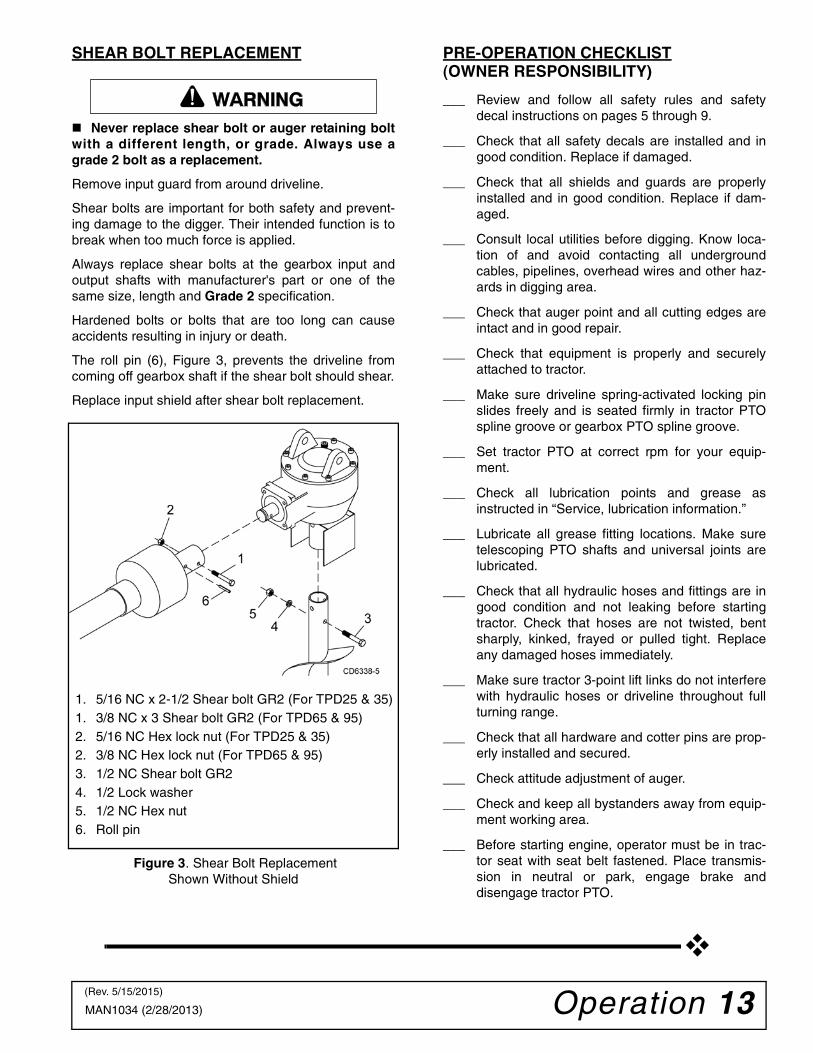
SHEAR BOLT REPLACEMENT
Never replace shear bolt or auger retaining boltwith a different length, or grade. Always use agrade 2 bolt as a replacement.
Remove input guard from around driveline.
Shear bolts are important for both safety and prevent-ing damage to the digger. Their intended function is tobreak when too much force is applied.
Always replace shear bolts at the gearbox input andoutput shafts with manufacturer's part or one of thesame size, length and Grade 2 specification.
Hardened bolts or bolts that are too long can causeaccidents resulting in injury or death.
The roll pin (6), Figure 3, prevents the driveline fromcoming off gearbox shaft if the shear bolt should shear.
Replace input shield after shear bolt replacement.
Figure 3. Shear Bolt ReplacementShown Without Shield
PRE-OPERATION CHECKLIST(OWNER RESPONSIBILITY)
___ Review and follow all safety rules and safetydecal instructions on pages 5 through 9.
___ Check that all safety decals are installed and ingood condition. Replace if damaged.
___ Check that all shields and guards are properlyinstalled and in good condition. Replace if dam-aged.
___ Consult local utilities before digging. Know loca-tion of and avoid contacting all undergroundcables, pipelines, overhead wires and other haz-ards in digging area.
___ Check that auger point and all cutting edges areintact and in good repair.
___ Check that equipment is properly and securelyattached to tractor.
___ Make sure driveline spring-activated locking pinslides freely and is seated firmly in tractor PTOspline groove or gearbox PTO spline groove.
___ Set tractor PTO at correct rpm for your equip-ment.
___ Check all lubrication points and grease asinstructed in “Service, lubrication information.”
___ Lubricate all grease fitting locations. Make suretelescoping PTO shafts and universal joints arelubricated.
___ Check that all hydraulic hoses and fittings are ingood condition and not leaking before startingtractor. Check that hoses are not twisted, bentsharply, kinked, frayed or pulled tight. Replaceany damaged hoses immediately.
___ Make sure tractor 3-point lift links do not interferewith hydraulic hoses or driveline throughout fullturning range.
___ Check that all hardware and cotter pins are prop-erly installed and secured.
___ Check attitude adjustment of auger.
___ Check and keep all bystanders away from equip-ment working area.
___ Before starting engine, operator must be in trac-tor seat with seat belt fastened. Place transmis-sion in neutral or park, engage brake anddisengage tractor PTO.
�������
1. 5/16 NC x 2-1/2 Shear bolt GR2 (For TPD25 & 35)1. 3/8 NC x 3 Shear bolt GR2 (For TPD65 & 95)2. 5/16 NC Hex lock nut (For TPD25 & 35)2. 3/8 NC Hex lock nut (For TPD65 & 95)3. 1/2 NC Shear bolt GR24. 1/2 Lock washer5. 1/2 NC Hex nut6. Roll pin
(Rev. 5/15/2015)
14 Owner Service MAN1034 (2/28/2013)
OWNER SERVICEThe information in this section is written for operatorswho possess basic mechanical skills. If you need help,your dealer has trained service technicians available.For your protection, read and follow all safety informa-tion in this manual.
Before performing any service or maintenance,lower digger to ground or block securely, turn offtractor engine, remove key, and disconnect drive-line from tractor PTO.
NEVER GO UNDERNEATH EQUIPMENT. Neverplace any part of the body underneath equipmentor between moveable parts even when the enginehas been turned off. Hydraulic system leak-down,hydraulic system failures, mechanical failures, ormovement of control levers can cause equipmentto drop or rotate unexpectedly and cause severeinjury or death.
• Service work does not require going under-neath implement.• Read Operator's Manual for service instruc-tions or have service performed by a qualifieddealer.
Keep all persons away from operator controlarea while performing adjustments, service, ormaintenance. Keep hands, feet, hair, and clothing away fromequipment while engine is running. Stay clear of allmoving parts.
Keep hands and body away from pressurizedlines. Use paper or cardboard, not hands or otherbody parts to check for leaks. Wear safety goggles.Hydraulic fluid under pressure can easily penetrateskin and will cause serious injury or death.
Make sure that all operating and service person-nel know that if hydraulic fluid penetrates skin, itmust be surgically removed as soon as possible bya doctor familiar with this form of injury or gan-grene, serious injury, or death will result. CON-TACT A PHYSICIAN IMMEDIATELY IF FLUIDENTERS SKIN OR EYES. DO NOT DELAY.
Always wear relatively tight and belted clothingto avoid getting caught in moving parts. Wearsturdy, rough-soled work shoes and protectiveequipment for eyes, hair, hands, hearing, and head;and respirator or filter mask where appropriate.
ROUTINE MAINTENANCE
1. Check that all bolts, nuts, and screws are tight.Checking the bolts and nuts on the cutting bladesis particularly important in rocky soil.
2. Check daily the level of the gearbox oil and top-offup to the correct level. Check for gearbox oil leaks.It should be noted that no warranty claim can besubmitted on a gearbox that has run dry. It isessential that the gearbox is kept correctly filledwith gearbox oil.
3. Grease the PTO shaft daily.
4. Check the wear on the cutting blades. Sharpenthem routinely with an angle grinder or replacewhen worn down too far. Keep at least two sets ofcutting blades, bolts, and nuts as spares.
LUBRICATION INFORMATION
When lubricating telescoping PTO drives, keepfingers out of shield access slots to prevent injury.
The accompanying chart gives the frequency of lubri-cation in operating hours, based on normal conditions.Severe or unusual conditions may require more fre-quent lubrication.
Do not let excess grease collect on or around parts,particularly when operating in sandy areas.
Use an SAE 90W gear lube in gearbox.
Use a lithium grease of No. 2 consistency with a MOLY(molybdenum disulfide) additive for all locations. Besure to clean fittings thoroughly before attachinggrease gun. When applied according to the lubricationchart, one good pump of most guns is sufficient. Do notover grease.
LUBRICATION CHART
Daily lubrication of the PTO slip joint is necessary. Fail-ure to maintain proper lubrication can result in damageto U-joints, gearbox, tractor PTO and/or driveline.
�������
�������
CAUTION
Ref. No. Description Frequency
1 Front U-Joint 8 Hours
2 Rear U-Joint 8 Hours
3 Rear U-Joint toInput Shaft
Seasonally
4Gearbox(Fill to proper level)
Check Daily
CAUTION

Owner Service 15MAN1034 (2/28/2013)
STORAGE
1. Drain and change the oil in your gearbox.
2. Check and replace, where necessary, blades,bolts, nuts on the machine.
3. Clean machine and touch up any rust spots thatmay have appeared.
4. Replace any safety signs if damaged or paintedover.
5. Make sure PTO driveline yoke and gearbox inputshaft are clean and free of burrs. Keep welllubricated to prevent galling of yoke and input shaftwhen shear bolt becomes sheared.
6. Keep all shields in place. Order new shields ifdamaged or missing.
7. Keep cutting edges sharp. Sharp cutting edges digeasier and better. Outer cutting edges on largeraugers wear faster than inner cutting edges;switching teeth will even wear.
8. Store implement in clean, dry location.
REMOVE DIGGER FROM TRACTOR
Optional parking stand is also available. Check withdealer for availability.
Post hole diggers when off the tractor, can be an awk-ward piece of equipment to handle. Be careful not topinch hands and fingers in the various hinge points ofthe digger.
If possible, it is suggested to hang the digger from anoverhead rafter or beam. Attach the chain or ropearound the boom just ahead of the gearbox. Thisallows one man to easily reconnect the digger to thetractor when next use is required.
If storing outside, another idea is to dig a hole about12-18 inches deep. Then shut the PTO off while theauger is in the hole. Set parking brake, turn off engine,and disconnect the digger from the tractor. The augerin the hole will keep the unit upright and make it possi-ble for one man to disconnect or reconnect to the trac-tor. Doing this, will cause rusting of the auger, but it iseasy for one man to handle the unit.
REPLACE CUTTING EDGE
Cutting edges and center points are replaceable. Theyshould be sharpened or replaced when worn.
1. Remove carriage bolt (4), lock washer (5), and hexnut (6) holding cutting tooth to the auger.
2. Replace or sharpen cutting tooth. Install carriagebolt, lock washer, and hex nut previously removed.
3. Remove center point (1) by removing cap screw(3), lock washer (5), and hex nut (6).
Figure 4. Cutting Tooth Replacement
POST HOLE DIGGER OPTIONS
1. Hydraulic Down Force Kit: For tough, hard soilconditions. This will allow operator to put 300-400lbs. of down force on the auger to force cuttingedges into tough or hard ground. Tractor musthave auxiliary hydraulic outlet. Order part number1009336 for models TPD25 and TPD35. Order partnumber 1009366 for models TPD65 and TPD95.
2. Parking Stand: Order part number 1009324 formodel TPD25. Order part number 1009334 formodels TPD35 and TPD65 and order part number1009392 for model TPD95.
3. Category 0 Mounting Pin Kit: (For use on model TPD25 only) Order part number 1009326.
4. Category 2 Bushing Kit: (For use on models TPD35, TPD65 and TPD95 only) Order part number 1003832.
5. 12" Auger Extension: (For use on models TPD35, TPD65 and TPD95 only) Available for situations where deeper holes are required. Note: Smaller tractors may not raise auger high enough to clear hole when 12" extension is used. Order part number 1009333.
6. Heavy-Duty Auger: (For use with models TPD35, TPD65 and TPD95 only) Augers with heavier flighting and reinforced drive tube are available for rocky or tough soil conditions. Check dealer for availability.
16 Owner Service MAN1034 (2/28/2013)
CLEAN POST HOLE DIGGER
After Each Use● Remove large debris such as clumps of dirt, grass,
crop residue, etc. from machine.
● Inspect machine and replace worn or damagedparts.
● Replace any safety decals that are missing or notreadable.
Periodically or Before Extended Storage● Clean large debris such as clumps of dirt, grass,
crop residue, etc. from machine.
● Remove the remainder using a low-pressure waterspray.
1. Be careful when spraying near scratched or tornsafety decals or near edges of decals as waterspray can peel decal off surface.
2. Be careful when spraying near chipped orscratched paint as water spray can lift paint.
3. If a pressure washer is used, follow the adviceof the pressure washer manufacturer.
● Inspect machine and replace worn or damagedparts.
● Sand down scratches and the edges of areas ofmissing paint and coat with Woods spray paint ofmatching color (purchase from your Woodsdealer).
● Replace any safety decals that are missing or notreadable (supplied free by your Woods dealer).See Safety Decals section for location drawing.

Troubleshooting 17MAN1034 (2/28/2013)
TROUBLESHOOTINGPROBLEM POSSIBLE CAUSES & SOLUTION
Auger will not dig Shear bolt sheared – install new shear bolt.
Teeth dull – sharpen or replace.
Ground too dry and hard – order optional down force kit, or wait until itrains.
Auger turning too fast and bouncing – reduce speed.
Tall grass has wrapped around auger teeth – remove grass.
Auger encountering rocks, roots, or other obstruction – lift auger from holeand inspect.
Auger teeth improperly positioned – see Parts section in this manual forproper tooth pattern.
Post hole digger sways side to side No sway bars or sway blocks on tractor – add same.
Lift arms not adjusted evenly – adjust lift arms.
Post hole digger is mounted with excessive looseness in the hitchconnecting points – use proper size pins or bushings.
Bent auger flighting or bent auger Tractor moved while auger was turning in hole – always set brakes ontractor and make sure it is out of gear.
Operator moved tractor with auger in hole to try and straighten a holebeing dug at an angle.
Auger is encountering rocks or roots or other foreign objects – removeobject from hole or change location.
Outer edge of auger flighting is bending due to contact with rocks or roots– use heavy-duty auger with thicker flighting.
Shear bolt has been replaced with harder bolt – replace with Grade 2 boltper instructions.
Auger screws itself into the ground Operator did NOT ease 3-point hitch to ground slowly.
Tractor 3-point does not have position control. Lift auger after advancingevery 3" - 4".
Faulty 3-point hitch hydraulic system on tractor.
Draft control is not in OFF position.
Tractor is too small to handle digger.
Excessive vibration PTO driveline bearing cross is worn – replace.
PTO driveline assembly comes off input shaft of gearbox when shear bolt is sheared
Roll pin missing in yoke at gearbox input shaft. Install roll pin as perinstructions. THIS IS A DANGEROUS SAFETY HAZARD, CORRECTIMMEDIATELY!
Auger digs so far, but will not dig deeper
See solutions for above.
PTO assembly “bottoms out,” not allowing digger to lower – remove augerfrom digger and lower digger. Gearbox should lower to the ground; if not,PTO driveline assembly may need to be shortened.
PTO driveline interferes with swinging drawbar – swing drawbar out of theway or remove.
Tractor hydraulic system may be faulty – consult tractor dealer.
Soil could have hardpan layer 6"-10" below surface – use optional downforce kit (see list of optional equipment).
(Rev. 3/31/2017)

18 Troubleshooting MAN1034 (2/28/2013)
TROUBLESHOOTINGPROBLEM POSSIBLE CAUSES & SOLUTION
PTO driveline failure Operator raising post hole digger too high above ground when PTO isengaged – causes excessive PTO joint operating angle.
PTO is engaged while moving between holes. (Auger swings, whichcauses excessive PTO joint operating angle.)
Improper use of a hard shear bolt – use Grade 2 bolt per instructions.
Driveline has not been properly lubricated.
Engaging tractor PTO with engine at high rpm.
Digging holes too deep so that PTO driveline contacts ground.
Operating at high rpm.
Use of auger extension can require post hole digger to be lifted high,which can cause excessive PTO joint operating angle.
PTO driveline “galls” or “friction welds” to input shaft of gearbox
Tractor is a “low profile model” (one that is low to the ground). Due to thelow height of the tractor, the digger must be raised higher to have thebottom of the auger clear the ground. Generally, low profile model tractorscan only use 30" long augers (standard auger length is 42"). Use adifferent tractor or purchase 30" long augers.
No lubrication on input shaft of gearbox to allow yoke of PTO driveline toturn freely on input shaft when shear bolt is sheared. Always keep inputshaft greased.
Gearbox failure No oil in gearbox.
Oil not changed per instructions.
Shear bolt has been replaced with a harder bolt – replace with Grade 2per instructions.
Bent output shaft is due to operator moving tractor when auger is in hole.
Gearbox overheating Low on lubricant – fill to proper level.
Improper type lubricant – replace with proper lubricant.
Auger bolts shear on gearbox output shaft
Shear bolt on input shaft has been replaced with a harder bolt – replacewith Grade 2 bolt as per instructions.
Tractor stalls Auger is encountering rocks or roots or other foreign object – removeobject or change hole location.
Tractor idle is not set correctly – tune tractor engine.
Assembly 19MAN1034 (2/28/2013)
ASSEMBLY INSTRUCTIONS
Keep hands, feet, hair, and clothing away fromequipment while engine is running. Stay clear of allmoving parts. Keep all persons away from operator controlarea while performing adjustments, service, ormaintenance.
Make sure spring-activated locking pin or collarslides freely and is seated firmly in tractor PTOspline groove.
Always wear relatively tight and belted clothingto avoid getting caught in moving parts. Wearsturdy, rough-soled work shoes and protectiveequipment for eyes, hair, hands, hearing, and head;and respirator or filter mask where appropriate.
DEALER SET-UP INSTRUCTIONS
Assembly of the post hole digger is the responsibility ofthe WOODS dealer. It should be delivered to the ownercompletely assembled, lubricated, and adjusted fornormal conditions.
The digger is shipped partially assembled. Assemblywill be easier if the components are aligned and looselyassembled before tightening hardware. Recommendedtorque values for hardware are located on page 41.
Select a suitable working area. Open parts boxes andlay out parts and hardware to make location easy.Refer to illustrations, accompanying text, parts lists andexploded view drawings.
IMPORTANT■ Post hole digger gearboxes are shipped with-out lubrication. Gearboxes must be serviced with90W gear lube before operation.
ATTACH A-FRAME TO BOOM - TPD25
A tractor is required during assembly of post hole dig-ger. A tractor will make part fit-up, part alignment, andpart handling easier.
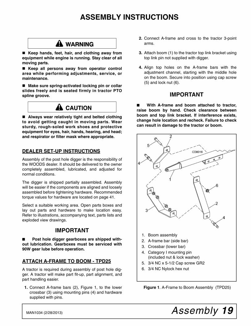
1. Connect A-frame bars (2), Figure 1, to the lowercrossbar (3) using mounting pins (4) and hardwaresupplied with pins.
2. Connect A-frame and cross to the tractor 3-pointarms.
3. Attach boom (1) to the tractor top link bracket usingtop link pin not supplied with digger.
4. Align top holes on the A-frame bars with theadjustment channel, starting with the middle holeon the boom. Secure into position using cap screw(5) and lock nut (6).
IMPORTANT
■ With A-frame and boom attached to tractor,raise boom by hand. Check clearance betweenboom and top link bracket. If interference exists,change hole location and recheck. Failure to checkcan result in damage to the tractor or boom.
Figure 1. A-Frame to Boom Assembly (TPD25)
�������
CAUTION
1. Boom assembly2. A-frame bar (side bar)3. Crossbar (lower bar)4. Category I mounting pin
(included nut & lock washer)5. 3/4 NC x 5-1/2 Cap screw GR26. 3/4 NC Nylock hex nut

20 Assembly MAN1034 (2/28/2013)
ATTACH A-FRAME TO BOOM - TPD35, TPD65 & TPD95
A tractor is required during assembly of post hole dig-ger. A tractor will make part fit-up, part alignment, andpart handling easier.
1. Connect mounting pins (3), Figure 2, and hardwaresupplied with pins to the yoke assembly (2).
NOTE: On tractors with 3-point arm spacing of 32inches, place mounting pins on the outside of theyoke assembly. On tractors with 3-point arm spac-ing of 26 inches or less, place mounting pins on theinside of the yoke assembly.
NOTE: Bushing kit 1003832 will be needed fortractors with a Category 2 hitch. Always use bush-ing kit when using Category 1 pins on a Category 2hitch. Post hole digger will have a loose fit and beunstable.
2. Connect yoke assembly to the tractor 3-point arms.
3. Attach boom (1) to the tractor top link bracket usingsleeve (4), and top link pin not supplied with digger.
4. Align yoke assembly with the adjustment channelon the boom, starting with the middle hole. Secureinto position using boom adjustment pin (5) andtwo cotter pins (6).
IMPORTANT With boom attached to tractor, raise boom byhand. Check clearance between boom and top linkbracket. If interference exists, change hole locationand recheck. Failure to check can result in damageto the tractor or boom.
Figure 2. A-Frame to Boom Assembly (TPD35, TPD65 & TPD95)
1. Boom assembly2. Yoke assembly3. Category 1 mounting pin
(includes nut & lock washer)4. Top link sleeve, Cat 1 to Cat 25. Boom adjustment pin6. 3/16 x 1-1/2 Cotter pin

Assembly 21MAN1034 (2/28/2013)
INSTALL SAFETY SHIELDS
1. Place gearbox upside down on a suitable worksurface.
2. Attach output shield (2), Figure 3, around theoutput shaft and secure to gearbox using four capscrews (6) and flat washers (7). Position shieldopening to the front.
3. Attach input guard mounting bracket (3) over inputshaft and secure to gearbox using four cap screws(6) and flat washers (7).
4. Attach input guard (4) to the input guard mountingbracket (3) and secure with two threaded knobs(5). Retaining chain (8) keeps guard and mountingbracket together.
Figure 3. Safety Shield Installation
ATTACH GEARBOX TO BOOM1. Attach desired auger (A), Figure 4, to output shaft
of gearbox (2). Secure with two grade 2 shear bolts(5), lock washers (6), and hex nuts (7). Do nottighten hardware at this time.
2. Stand gearbox and auger assembly on augerpoint.
3. Place gearbox and auger assembly under boomand slowly lower 3-point arms of tractor.
4. Align gearbox mounting lug and boom. Securetogether using gearbox hitch pin (3) and two cotterpins (4).
Figure 4. Gearbox to Boom Installation
1. Gearbox2. Output shield3. Input guard mounting bracket4. Input guard5. Knob6. Screw7. Flat washer8. Shield tether chain
A. Auger1. Boom2. Gearbox3. Pin4. Cotter pin5. 1/2 NC Shear bolt GR26. 1/2 Lock washer7. 1/2 NC Hex nut
22 Assembly MAN1034 (2/28/2013)
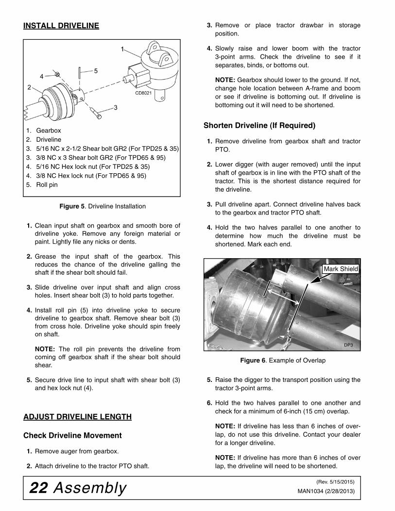
INSTALL DRIVELINE
Figure 5. Driveline Installation
1. Clean input shaft on gearbox and smooth bore ofdriveline yoke. Remove any foreign material orpaint. Lightly file any nicks or dents.
2. Grease the input shaft of the gearbox. Thisreduces the chance of the driveline galling theshaft if the shear bolt should fail.
3. Slide driveline over input shaft and align crossholes. Insert shear bolt (3) to hold parts together.
4. Install roll pin (5) into driveline yoke to securedriveline to gearbox shaft. Remove shear bolt (3)from cross hole. Driveline yoke should spin freelyon shaft.
NOTE: The roll pin prevents the driveline fromcoming off gearbox shaft if the shear bolt shouldshear.
5. Secure drive line to input shaft with shear bolt (3)and hex lock nut (4).
ADJUST DRIVELINE LENGTH
Check Driveline Movement
1. Remove auger from gearbox.
2. Attach driveline to the tractor PTO shaft.
3. Remove or place tractor drawbar in storageposition.
4. Slowly raise and lower boom with the tractor3-point arms. Check the driveline to see if itseparates, binds, or bottoms out.
NOTE: Gearbox should lower to the ground. If not,change hole location between A-frame and boomor see if driveline is bottoming out. If driveline isbottoming out it will need to be shortened.
Shorten Driveline (If Required)
1. Remove driveline from gearbox shaft and tractorPTO.
2. Lower digger (with auger removed) until the inputshaft of gearbox is in line with the PTO shaft of thetractor. This is the shortest distance required forthe driveline.
3. Pull driveline apart. Connect driveline halves backto the gearbox and tractor PTO shaft.
4. Hold the two halves parallel to one another todetermine how much the driveline must beshortened. Mark each end.
Figure 6. Example of Overlap
5. Raise the digger to the transport position using thetractor 3-point arms.
6. Hold the two halves parallel to one another andcheck for a minimum of 6-inch (15 cm) overlap.
NOTE: If driveline has less than 6 inches of over-lap, do not use this driveline. Contact your dealerfor a longer driveline.
NOTE: If driveline has more than 6 inches of overlap, the driveline will need to be shortened.
1. Gearbox2. Driveline3. 5/16 NC x 2-1/2 Shear bolt GR2 (For TPD25 & 35)3. 3/8 NC x 3 Shear bolt GR2 (For TPD65 & 95)4. 5/16 NC Hex lock nut (For TPD25 & 35)4. 3/8 NC Hex lock nut (For TPD65 & 95)5. Roll pin
Mark Shield
DP3
(Rev. 5/15/2015)

Assembly 23MAN1034 (2/28/2013)
Cut Driveline
1. Place driveline half in a padded vise and cut shieldoff at the determined length.
Figure 7. Cut Shield (Example)
2. Place the cutoff portion of the shield against theend of the shaft and use it as a guide. Mark and cutthe shaft.
Figure 8. Cut Shaft to Length
3. Repeat steps for other drive half.
4. File and clean cut ends of the both drive halves.
5. Apply a multi-purpose grease to the outside of themale drive half. Slide the two drive halves together.
6. Connect driveline to gearbox and tractor PTO.
Make sure spring-activated locking pin or collarslides freely and is seated firmly in tractor PTOspline groove.
7. Make sure roll pin is installed in driveline yoke tosecure driveline to gearbox input shaft.
8. Carefully raise and lower the digger to check thatthe driveline does not pull apart or bind through itsrange of motion.
9. Use stabilizer bars, adjustable sway chains, orsway blocks on your tractor lift arms to keep the
post hole digger from swaying side to side. Adjustas tightly as practical for best performance.
FILL GEARBOX1. Level gearbox and remove top fill plug and top
sight plug on back side of gearbox.
2. Fill gearbox with SAE 90W gear lube per modelspecific amount listed below or until oil runs out ofsight hole.
TPD25 and TPD35: 50 ounces (1.5 Liters)
TPD65: 59 ounces (1.75 Liters)
TPD95: 100 ounces (2.9 Liters)
3. Install both plugs.
INSTALL HANDLE1. Slide handle (3), Figure 9, through hole in input
guard mounting bracket (2) and opening in side ofgearbox.
2. Secure to gearbox using cap screw (4).
Figure 9. Handle Installed
Adjust Handle
Handle is used to position the auger as you lower thetip to the ground. You should be able to easily reachhandle while seated in the tractor seat and operate thetractor 3-point lift arms. Adjust as necessary.
1. Bend handle as necessary to provide easy accessfrom the tractor seat.
2. Shorten Handle: Remove plastic handle grip. Cuthandle to desired length. Replace handle grip.
�������
DP6
1. Gearbox2. Input guard mounting bracket3. Handle4. 5/16 NC x 3/4 Cap screw
(Rev. 1/31/2014)
24 Assembly MAN1034 (2/28/2013)
3. Lengthen Handle: Remove plastic handle grip.Weld extension of desired length to handle. Usesame size tubing (7/8") as handle. Paint andreplace handle grip.
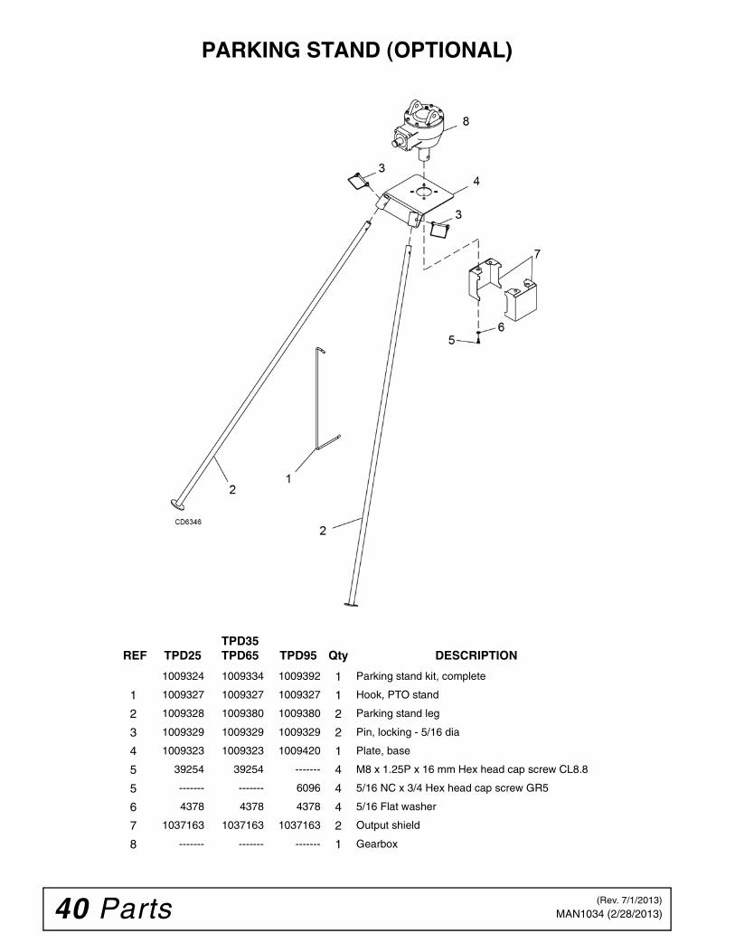
INSTALL PARKING STAND (OPTIONAL)
Figure 10. Parking Stand Installation
1. Remove auger from digger.
2. Remove hardware and output shield (7) frombottom of gearbox, Figure 10.
3. Attach parking stand base plate (4) and outputshield (7) over the output shaft. Secure to thebottom of the gearbox using four new cap screws(5) and flat washers (6) supplied with the parkingstand kit.
4. Install auger to output shaft using two cap screwspreviously removed.
5. Raise digger to the transport position.
6. Insert the two stand legs (2) into the socket on thefront of the parking stand base plate. Secure withtwo locking pins (3).
7. Lower digger until the two legs and the auger forma tripod. This will support the post hole digger in avertical position.
8. Remove 3-point arms and driveline from thetractor.
9. Attach the PTO hook (1) to the boom of the digger.
10. Hang the driveline from the hook to help preventdirt and debris from accumulating in the lockingcollar on the driveline PTO yoke.
INSTALL DOWN FORCE KIT (OPTIONAL)
Install Pivot Plates and Cylinder
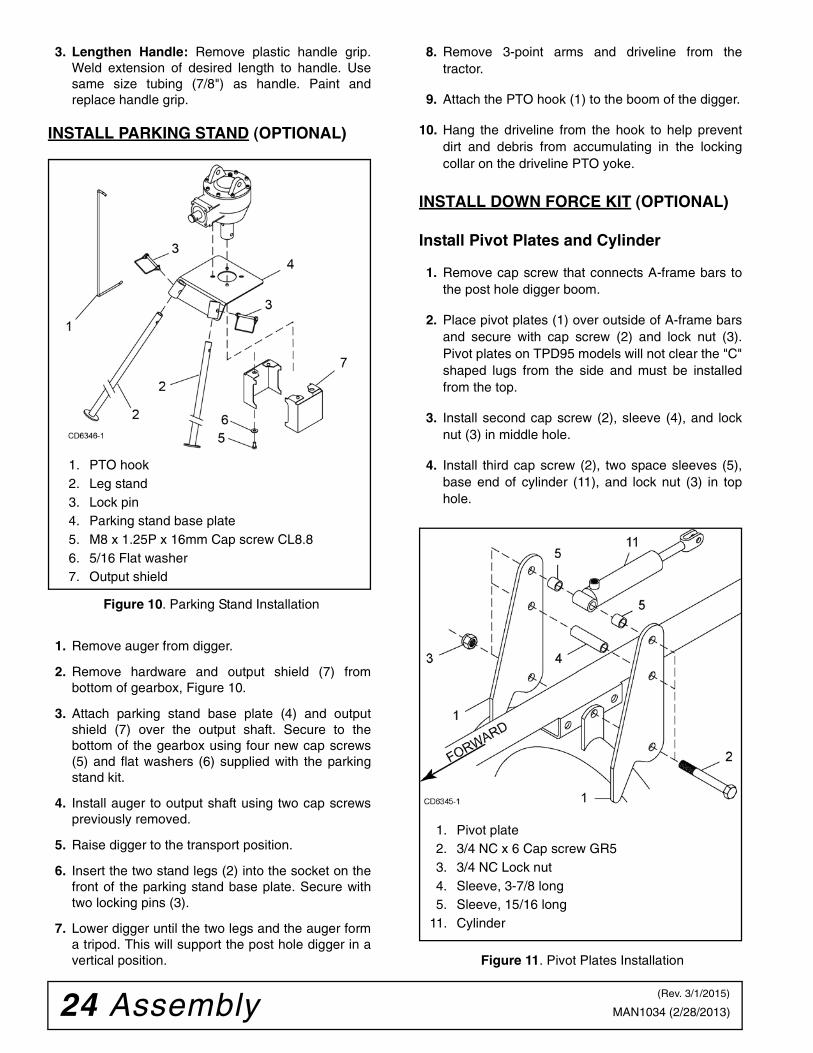
1. Remove cap screw that connects A-frame bars tothe post hole digger boom.
2. Place pivot plates (1) over outside of A-frame barsand secure with cap screw (2) and lock nut (3).Pivot plates on TPD95 models will not clear the "C"shaped lugs from the side and must be installedfrom the top.
3. Install second cap screw (2), sleeve (4), and locknut (3) in middle hole.
4. Install third cap screw (2), two space sleeves (5),base end of cylinder (11), and lock nut (3) in tophole.
Figure 11. Pivot Plates Installation
1. PTO hook2. Leg stand3. Lock pin4. Parking stand base plate5. M8 x 1.25P x 16mm Cap screw CL8.86. 5/16 Flat washer7. Output shield
1. Pivot plate2. 3/4 NC x 6 Cap screw GR53. 3/4 NC Lock nut4. Sleeve, 3-7/8 long5. Sleeve, 15/16 long
11. Cylinder
(Rev. 3/1/2015)

Assembly 25MAN1034 (2/28/2013)
Install Cylinder Clamps1. Make sure cylinder (11) is retracted.
2. Place cylinder clamps (6, top) and (7, bottom)around boom, Figure 13.
3. Loosely secure to boom using two cap screws (8),lock washers (9), and hex nuts (10). Clamp shouldslip on boom.
4. Attach cylinder to top clamp using cap screw (12)and lock nut (13).
5. Raise post hole digger to the full transport position.
6. With cylinder retracted, torque clamp bolts to 300lbs-ft.
NOTE: It may be necessary to retighten clampbolts after initial use to keep the clamp from slip-ping.
Figure 12. Cylinder Clamps Installation
Install Relief Valve and Hoses1. Attach adapter (17) and relief valve (14) to the
cylinder.
2. Attach male quick coupler (not supplied in kit) toPRESSURE hose (15). Attach hose to the top porton the relief valve.
3. Attach adapter (18) and RETURN hose (16) to theside port on the relief valve.
4. Connect opposite end of RETURN hose directly tothe tractor hydraulic reservoir.
NOTE: Fitting for this connection are not suppliedwith this kit.
IMPORTANT
■ Do not connect RETURN hose to a remote out-let. Remote outlet ports are blocked in the neutralposition and will damage the hydraulic cylinderwhen boom is raised.
Figure 13. Relief Valve and Hoses Installation
Install Decal 1009330 on left side of pivot plate.
Figure 14. Down Force Kit Installed
6. Clamp, top7. Clamp, bottom8. 3/4 NC x 3 Cap screw GR59. 3/4 Lock washer
10. 3/4 Hex nut12. 1/2 NC x 2 Cap screw GR513. 1/2 Lock nut
14. Relief valve15. Hose, 3/8 x 60”16. Hose, 3/8 x 72”17. Adapter, 3/8 NPTM x 1/2 NPTM18. Adapter, 3/8 NPTF x 1/2 NPTM
DECAL1009330
26 Dealer Check List MAN1034 (2/28/2013)
DEALER CHECK LISTS
PRE-DELIVERY CHECK LIST(DEALER’S RESPONSIBILITY)
Inspect digger thoroughly after assembly to ensure it isset up properly before delivering it to the customer. Thefollowing check list is a reminder of points to inspect.Check off each item as it is found satisfactory or aftercorrections are made.
IMPORTANT■ Gearbox was not filled at the factory. It must beserviced before operating post hole digger. Failureto service will result in damage to gearbox.
___ Check that all safety shielding and decals areproperly installed and in good condition.
___ Check all bolts to be sure they are tight.
___ Gearboxes are not filled at the factory. Prior todelivery, fill as specified in the Service, lubrica-tion information and check to see that there areno leaking seals.
___ Check that all cotter pins are properly installed.
___ Check that gearbox is serviced and not leak-ing.
___ Lubricate digger as specified in LUBRICATIONINFORMATION, page 14.
DELIVERY CHECK(DEALER’S RESPONSIBILITY)
___ Point out safety features and explain theimportance of safety decals and shielding.Explain the need to keep them properlyinstalled and in good condition.
___ Present Operator's Manual and ask customerto read it before operating cutter.
___ Show customer how to make adjustments andproperly mount digger to tractor.
___ Show customer how to make sure that drive-line is properly installed and that the spring-activated locking pin slides freely and is seatedin groove on tractor PTO shaft.
___ Instruct customer how to lubricate post holedigger and explain importance of lubrication.
___ Make customer aware of optional equipmentavailable for this digger.

Parts 27MAN1034 (2/28/2013)
PARTS INDEX
TPD25 POST HOLE DIGGER ASSEMBLY . . . . . . . . . . . . . . . . . . . 28 - 28
TPD35, TPD65 & TPD95 POST HOLE DIGGER ASSEMBLY . . . . 30 - 31
TPD25 & TPD35 GEARBOX ASSEMBLY . . . . . . . . . . . . . . . . . . . . . . . 32
TPD65 GEARBOX ASSEMBLY . . . . . . . . . . . . . . . . . . . . . . . . . . . . . . . 33
TPD95 GEARBOX ASSEMBLY . . . . . . . . . . . . . . . . . . . . . . . . . . . . . . . 34
TPD25 & TPD35 DRIVELINE ASSEMBLY . . . . . . . . . . . . . . . . . . . . . . 35
TPD65 & TPD95 DRIVELINE ASSEMBLY . . . . . . . . . . . . . . . . . . . . . . 36
TPD25 AUGER ASSEMBLY . . . . . . . . . . . . . . . . . . . . . . . . . . . . . . . . . 37
TPD35, TPD65 & TPD95 AUGER ASSEMBLY . . . . . . . . . . . . . . . . . . . 38
AUGER TOOTH MOUNTING PATTERN. . . . . . . . . . . . . . . . . . . . . . . . 37
DOWN PRESSURE KIT (OPTIONAL) . . . . . . . . . . . . . . . . . . . . . . . . . . 39
PARKING STAND ASSEMBLY . . . . . . . . . . . . . . . . . . . . . . . . . . . . . . . 40
Post Hole DiggerTPD25 - General PurposeTPD35 - Standard-DutyTPD65 - Heavy-DutyTPD95 - Heavy-Duty

28 Parts MAN1034 (2/28/2013)
TPD25 POST HOLE DIGGER ASSEMBLY

Parts 29MAN1034 (2/28/2013)
TPD25 POST HOLE DIGGER ASSEMBLY PARTS LIST
REF PART QTY DESCRIPTION
1 1035527 1 Boom frame
2 1037160 2 A-frame bar
3 1035578 1 Lower A-frame bracket
4 33661 2 Category 1 mounting pin(Includes items 4A & 4B)
4A 30008 2 7/8 Lock washer
4B 30007 2 7/8 NF Hex nut
5 2376 1 3/4 NC x 5 Hex head cap screw GR5
6 302207 1 3/4 NC Flange lock nut
7 1026530 1 Manual storage tube
8 24409* 2 5/16 NC x 1 Carriage bolt
9 14139* 2 5/16 NC Flange lock nut
10 1037122 1 Gearbox (See page 32)
11 1036152 1 Pin, headless .75 x 5.63
12 1285* 2 1/4 x 1-1/2 Cotter pin
13 1037163 2 Auger shield
14 39254 8 M8-1.25P x 14 mm Hex head cap screw
15 2472* 8 5/16 Lock washer
16 1037162 1 Gearbox input shield
REF PART QTY DESCRIPTION
17 1037161 1 Driveline shield
18 30917 1 Driveline shield tether chain
19 66840 2 3-Prong knob, 3/8 NC
20 1036155 1 Positioning handle
21 6096* 1 5/16 NC x 3/4 Hex head cap screw GR5
22 1036150 1 Driveline, complete (See page 35)
23 1036153 1 5/16 NC x 2-1/2 Shear bolt GR2
24 6778* 1 5/16 NC Lock nut
25 37208 1 3/16 x 2 Roll pin
26 --------- 1 Auger assembly (See page 37)
* Standard Hardware - Obtain Locally
(Rev. 12/14/2016)

30 Parts MAN1034 (2/28/2013)
TPD35, TPD65 & TPD95 POST HOLE DIGGER ASSEMBLY

Parts 31MAN1034 (2/28/2013)
TPD35, TPD65 & TPD95 POST HOLE DIGGER ASSEMBLY PARTS LIST
REF TPD35 TPD65 TPD95 Qty DESCRIPTION
1 1035537 1035567 1035597 1 Boom frame
2 1037164 1037165 1037168 1 Yoke frame
3 1009383 1009383 1009383 2 Pin, 3-point lift (Includes items 3A, 3B & 3C)
3A 37009 37009 37009 2 7/8 NF Jam nut
3B 30008 30008 30008 2 7/8 Lock washer
3C 30007 30007 30007 2 7/8 NF Hex nut
4 8325 8325 8325 1 Pin, headless .75 x 4.08
5 1285* 1285* 1285* 4 1/4 x 1-1/2 Cotter pin
6 1026530 1026530 1026530 1 Manual storage tube
7 24409* 24409* 24409* 2 5/16 NC x 1 Carriage bolt
8 14139* 14139* 14139* 2 5/16 NC Flange lock nut
9 1037122 1037123 1037124 1 Gearbox (See pages 32, 33 or 34)
10 1036152 1036154 1036154 1 Pin, headless - gearbox hitch
11 1037163 1037163 1037163 2 Auger shield
12 39254 --------- --------- 8 M8 - 1.25P x 14 mm Hex head cap screw
12 --------- 1686* --------- 8 3/8 NC x 3/4 Hex head cap screw GR5
12 --------- --------- 6096* 8 5/16 NC x 3/4 Hex head cap screw GR5
13 2472* --------- 2472* 8 5/16 Lock washer
13 --------- 838* --------- 8 3/8 Lock washer
14 1037162 1037166 1037169 1 Gearbox input shield
15 1037161 1037161 1037161 1 Driveline shield
16 30917 30917 30917 1 Driveline shield tether chain
17 66840 66840 66840 2 3-Prong knob, 3/8 NC
18 1036155 1036155 1036155 1 Positioning handle
19 6096* 6096* --------- 1 5/16 NC x 3/4 Hex head cap screw GR5
20 1036150 1036151 1036151 1 Driveline, complete (See pages 35 or 36)
21 1036153 --------- --------- 1 5/16 NC x 2-1/2 Shear bolt GR2
21 --------- 1036156 1036156 1 3/8 NC x 3 Shear bolt GR2
22 6778* --------- --------- 1 5/16 NC Lock nut
22 --------- 6698* 6698* 1 3/8 NC Lock nut
23 --------- 1035579 1035579 1 .78 x 1.00 x 1.00 Sleeve
24 37208 --------- --------- 1 3/16 x 2 Roll pin
24 --------- 21022 21022 1 1/4 x 2 Roll pin
25 --------- 1003831 1003831 2 Category 2 hitch sleeve (optional)
26 --------- --------- --------- 1 Auger assembly (See page 38)
27 --------- 565* --------- 4 3/8 Flat washer
* Standard Hardware - Obtain Locally
(Rev. 12/14/2016)

32 Parts MAN1034 (2/28/2013)
TPD25 & TPD35 GEARBOX ASSEMBLY
REF PART QTY DESCRIPTION
1037122 1 Gearbox, complete TPD25 & TPD35
1 N/A 1 Snap ring, 72 x 75 x 2.5
2 N/A 8 Washer, internal tooth 8.4 x 15
3 N/A 8 M8 x 22 Hex socket head screw
4 N/A 1 Cover
5 N/A 3 Plug, 3/8 solid
6 57478 2 Bearing cup & cone
7 N/A 2 Shim kit
8 N/A 1 Crown z30 m5
9 N/A 2 Key parallel 10 x 8 x 30
10 N/A 1 Output shaft
11 1009322 1 Oil seal 40 x 62 x 7
REF PART QTY DESCRIPTION
12 N/A 1 Casing
13 N/A 1 Pinion z10 m5
14 N/A 2 Shim kit (35.3 x 48)
15 1009321 1 Bearing, roller (35 x 72 x 1)
16 N/A 1 Spacer
17 20890 1 Bearing, ball 6207
18 1017477 1 Bushing
19 N/A 1 Snap ring (35 x 33 x 1.5)
20 57463 1 Seal, oil 35 x 72 x 10
21 1036152 1 Pin, headless .75 x 5.63
22 1285 2 1/4 x 1-1/2 Cotter pin
N/A Not available
Parts 33MAN1034 (2/28/2013)
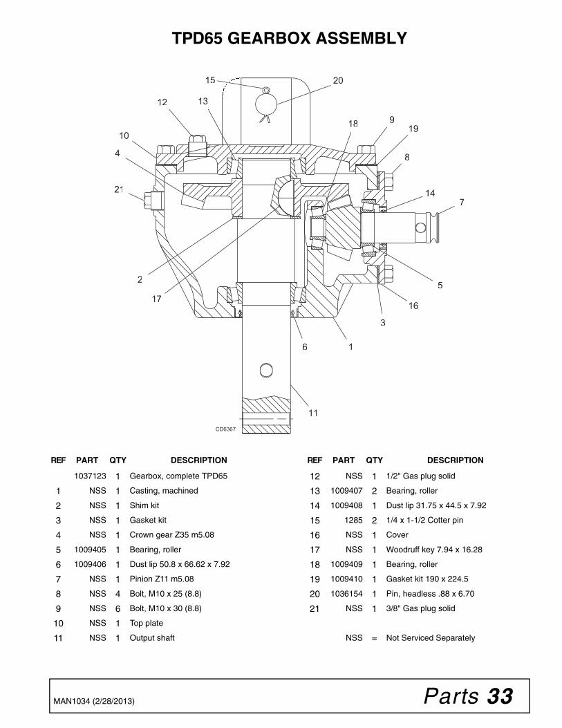
TPD65 GEARBOX ASSEMBLY
1
2
3
4
5
6
7
8
9
10
11
12 13
14
15
1617
1819
20
21
CD6367
REF PART QTY DESCRIPTION
1037123 1 Gearbox, complete TPD65
1 NSS 1 Casting, machined
2 NSS 1 Shim kit
3 NSS 1 Gasket kit
4 NSS 1 Crown gear Z35 m5.08
5 1009405 1 Bearing, roller
6 1009406 1 Dust lip 50.8 x 66.62 x 7.92
7 NSS 1 Pinion Z11 m5.08
8 NSS 4 Bolt, M10 x 25 (8.8)
9 NSS 6 Bolt, M10 x 30 (8.8)
10 NSS 1 Top plate
11 NSS 1 Output shaft
REF PART QTY DESCRIPTION
12 NSS 1 1/2" Gas plug solid
13 1009407 2 Bearing, roller
14 1009408 1 Dust lip 31.75 x 44.5 x 7.92
15 1285 2 1/4 x 1-1/2 Cotter pin
16 NSS 1 Cover
17 NSS 1 Woodruff key 7.94 x 16.28
18 1009409 1 Bearing, roller
19 1009410 1 Gasket kit 190 x 224.5
20 1036154 1 Pin, headless .88 x 6.70
21 NSS 1 3/8" Gas plug solid
NSS = Not Serviced Separately

34 Parts MAN1034 (2/28/2013)
TPD95 GEARBOX ASSEMBLY
REF PART QTY DESCRIPTION
1037124 1 Gearbox, complete TPD95
1 21542 8 Washer, lock 10 mm
2 307201 8 M10 x 1.5P x 30 mmHex head cap screw
3 NSS 1/2" Pipe plug
4 1009423 2 Bearing assembly, cup and cone (output shaft)
5 1009421 1 Input shaft seal
6 1009422 2 Ball bearing (input shaft)
7 1009424 1 Output shaft seal
REF PART QTY DESCRIPTION
8 1285 2 1/4 x 1-1/2 Cotter pin
9 1036154 1 Pin, headless .88 x 6.70
NSS Not Serviced Separately

Parts 35MAN1034 (2/28/2013)
TPD25 & TPD35 DRIVELINE ASSEMBLY
REF PART QTY DESCRIPTION
1036150 1 Driveline, complete
1 1009374 1 Yoke, complete w/zerk
2 41534 2 Cross, journal set
5 1032423 1 Outer yoke
11 1032424 1 Roll pin for outer yoke
14 1032425 1 Outer tube
15 1032416 1 Inner tube
16 1032415 1 Roll pin for inner tube
21 1032414 1 Inner yoke
30 1009376 1 Complete yoke collar
31 1009377 1 Collar, retaining guard outer
37 1009378 1 Collar, retaining guard inner
40 1025873 1 Guard, complete w/manual
REF PART QTY DESCRIPTION
51 N/A 1 Grease zerk M8 x 1
52 N/A 1 Special yoke
71 N/A 1 Collar yoke C12
90 N/A 1 Female tube yoke w/ pin & decal
91 N/A 1 Male tube yoke w/ pin
94 N/A 1 Guard, female half
95 N/A 1 Guard, male half
98 33347 1 Danger decal, guard missing
99 18864 1 Danger decal, rotating driveline
100 N/A 1 Manual, instruction
200 1001340 1 Lock collar repair kit
N/A Not available

36 Parts MAN1034 (2/28/2013)
TPD65 & TPD95 DRIVELINE ASSEMBLY
98
1 2 2 30
40
99
200
31 37
CD6366
REF PART QTY DESCRIPTION
1036151 1 Driveline, complete
1 1001300 1 Complete collar yoke
2 38478 2 U-joint repair kit
30 1009400 1 Yoke, special implement end
31 1009401 1 Collar, outer guard retainer
37 1009402 1 Collar, inner guard retainer
40 1009403 1 Guard, complete with manual
98 33347 1 Decal, Danger guard missing
99 18864 1 Decal, Danger rotating driveline
200 1009404 1 Kit, slide lock collar repair

Parts 37MAN1034 (2/28/2013)
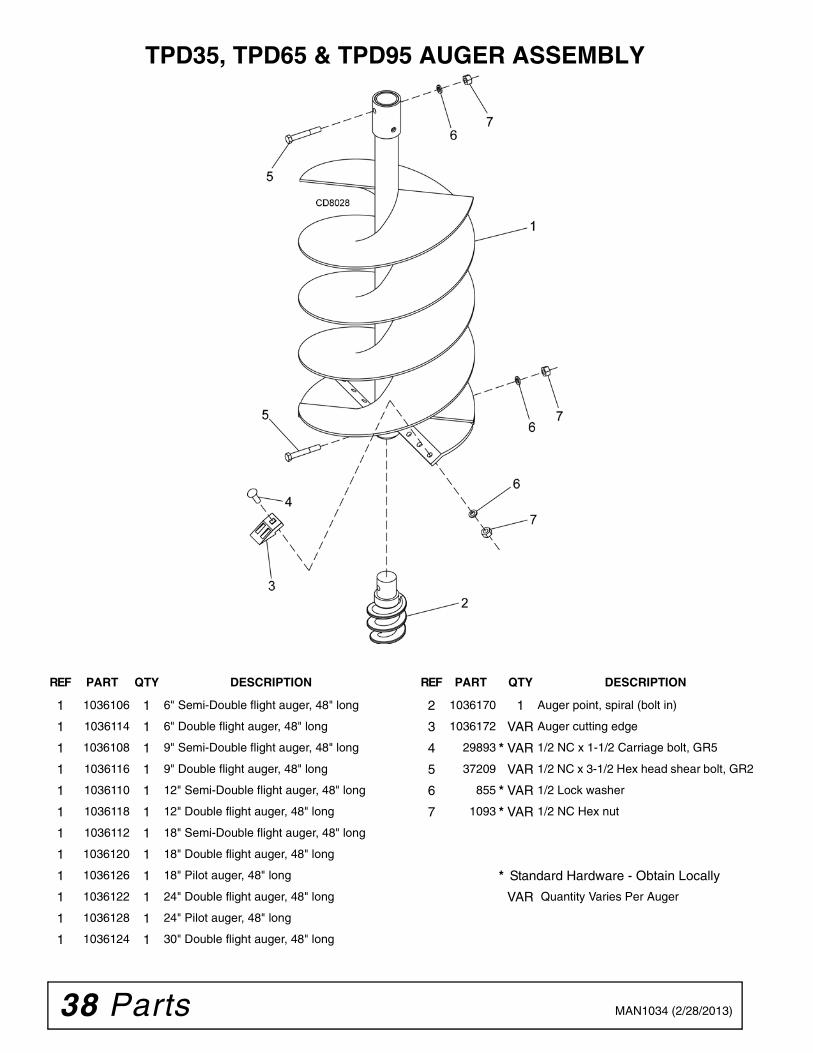
TPD25 AUGER ASSEMBLY
AUGER TOOTH MOUNTING PATTERN
REF PART QTY DESCRIPTION
1 1036100 1 6" Semi-Double flight auger, 36" long
1 1036102 1 9" Semi-Double flight auger, 36" long
1 1036104 1 12" Semi-Double flight auger, 36" long
2 1036170 1 Auger point, spiral (bolt in)
3 1036172 VAR Auger cutting edge
4 29893 * VAR 1/2 NC x 1-1/2 Carriage bolt, GR5
5 15349 VAR 1/2 NC x 3 Hex head shear bolt GR2
6 855 * VAR 1/2 Lock washer
7 1093 * VAR 1/2 NC Hex nut
* Standard Hardware - Obtain Locally
VAR Quantity Varies Per Auger
38 Parts MAN1034 (2/28/2013)
TPD35, TPD65 & TPD95 AUGER ASSEMBLY
REF PART QTY DESCRIPTION
1 1036106 1 6" Semi-Double flight auger, 48" long
1 1036114 1 6" Double flight auger, 48" long
1 1036108 1 9" Semi-Double flight auger, 48" long
1 1036116 1 9" Double flight auger, 48" long
1 1036110 1 12" Semi-Double flight auger, 48" long
1 1036118 1 12" Double flight auger, 48" long
1 1036112 1 18" Semi-Double flight auger, 48" long
1 1036120 1 18" Double flight auger, 48" long
1 1036126 1 18" Pilot auger, 48" long
1 1036122 1 24" Double flight auger, 48" long
1 1036128 1 24" Pilot auger, 48" long
1 1036124 1 30" Double flight auger, 48" long
REF PART QTY DESCRIPTION
2 1036170 1 Auger point, spiral (bolt in)
3 1036172 VAR Auger cutting edge
4 29893 * VAR 1/2 NC x 1-1/2 Carriage bolt, GR5
5 37209 VAR 1/2 NC x 3-1/2 Hex head shear bolt, GR2
6 855 * VAR 1/2 Lock washer
7 1093 * VAR 1/2 NC Hex nut
* Standard Hardware - Obtain Locally
VAR Quantity Varies Per Auger

Parts 39MAN1034 (2/28/2013)
DOWN PRESSURE KIT (OPTIONAL)
REF TPD25 TPD35 TPD65 TPD95 Qty DESCRIPTION
1009336 1009366 1035575 1 Down force kit (optional)
1 1009361 1009361 1035576 1 Plate, pivot - down pressure
2 2377 2377 2377 3 3/4 NC x 6 Hex head cap screw GR5
3 FA446 FA446 FA446 3 3/4 NC Nylock nut
4 1009362 1009362 1009362 1 Sleeve, 3-7/8 long
5 1009363 1009363 1009363 2 Sleeve, 15/16 long
6 1009364 1009397 1009397 1 Upper clamp
7 1009367 1009398 1009398 1 Lower clamp
8 14334 14334 14334 2 3/4 NC x 3 Hex head cap screw GR5
9 2522 2522 2522 2 3/4 Lock washer
10 1450 1450 1450 2 3/4 NC Hex nut
11 1009368 1009368 1009368 1 Hydraulic cylinder, down pressure
-- 1009373 1009373 1009373 1 Hydraulic cylinder seal repair kit
12 3699 3699 3699 1 1/2 NC x 2 Hex head cap screw GR5
13 6241 6241 6241 1 1/2 NC Elastic stop nut
14 1009369 1009369 1009369 1 Relief valve, down pressure
15 1009370 1009370 1009370 1 Hydraulic hose, 3/8 x 60"
16 1009371 1009371 1009371 1 Hydraulic hose, 3/8 x 72"
17 34234 34234 34234 1 Adapter, 3/8 NPTM x 1/2 NPTM
18 10802 10802 10802 1 Adapter, 3/8 NPTF x 1/2 NPTM
(Rev. 3/1/2015)
40 Parts MAN1034 (2/28/2013)
PARKING STAND (OPTIONAL)
REF TPD25 TPD35 TPD65 TPD95 Qty DESCRIPTION
1009324 1009334 1009392 1 Parking stand kit, complete
1 1009327 1009327 1009327 1 Hook, PTO stand
2 1009328 1009380 1009380 2 Parking stand leg
3 1009329 1009329 1009329 2 Pin, locking - 5/16 dia
4 1009323 1009323 1009420 1 Plate, base
5 39254 39254 ------- 4 M8 x 1.25P x 16 mm Hex head cap screw CL8.8
5 ------- ------- 6096 4 5/16 NC x 3/4 Hex head cap screw GR5
6 4378 4378 4378 4 5/16 Flat washer
7 1037163 1037163 1037163 2 Output shield
8 ------- ------- ------- 1 Gearbox
(Rev. 7/1/2013)

Appendix 41Bolt Torque & Size Charts (Rev. 3/28/2007)
BOLT TORQUE CHARTAlways tighten hardware to these values unless a different torque value or tightening procedure is listed for a specific application.Fasteners must always be replaced with the same grade as specified in the manual parts list.Always use the proper tool for tightening hardware: SAE for SAE hardware and Metric for metric hardware.Make sure fastener threads are clean and you start thread engagement properly. All torque values are given to specifications used on hardware defined by SAE J1701 MAR 99 & J1701M JUL 96.
Diameter (Inches)
WrenchSize
MARKING ON HEAD
SAE 2 SAE 5 SAE 8
lbs-ft N-m lbs-ft N-m lbs-ft N-m
1/4" 7/16" 6 8 10 13 14 18
5/16" 1/2" 12 17 19 26 27 37
3/8" 9/16" 23 31 35 47 49 67
7/16" 5/8" 36 48 55 75 78 106
1/2" 3/4" 55 75 85 115 120 163
9/16" 13/16" 78 106 121 164 171 232
5/8" 15/16" 110 149 170 230 240 325
3/4" 1-1/8" 192 261 297 403 420 569
7/8" 1-5/16" 306 416 474 642 669 907
1" 1-1/2" 467 634 722 979 1020 1383
Diameter & Thread Pitch (Millimeters)
Wrench Size
Coarse Thread Fine Thread
Diameter & Thread Pitch (Millimeters)
Marking on Head Marking on Head
Metric 8.8 Metric 10.9 Metric 8.8 Metric 10.9
N-m lbs-ft N-m lbs-ft N-m lbs-ft N-m lbs-ft
6 x 1.0 10 mm 8 6 11 8 8 6 11 8 6 x 1.0
8 x 1.25 13 mm 20 15 27 20 21 16 29 22 8 x 1.0
10 x 1.5 16 mm 39 29 54 40 41 30 57 42 10 x 1.25
12 x 1.75 18 mm 68 50 94 70 75 55 103 76 12 x 1.25
14 x 2.0 21 mm 109 80 151 111 118 87 163 120 14 x 1.5
16 x 2.0 24 mm 169 125 234 173 181 133 250 184 16 x 1.5
18 x 2.5 27 mm 234 172 323 239 263 194 363 268 18 x 1.5
20 x 2.5 30 mm 330 244 457 337 367 270 507 374 20 x 1.5
22 x 2.5 34 mm 451 332 623 460 495 365 684 505 22 x 1.5
24 x 3.0 36 mm 571 421 790 583 623 459 861 635 24 x 2.0
30 x 3.0 46 mm 1175 867 1626 1199 1258 928 1740 1283 30 x 2.0
A
SAE SERIES TORQUE CHART
SAE Bolt Head Identification
SAE Grade 2(No Dashes)
SAE Grade 5(3 Radial Dashes)
SAE Grade 8(6 Radial Dashes)
A
METRIC SERIES TORQUE CHART
Metric Bolt Head Identification
8.8
MetricGrade 10.9
10.9
MetricGrade 8.8
A
A A
Typical Washer Installations Lock Washer
Flat Washer
8/9/00
Bolt

Bolt Torque & Size Charts (Rev. 3/28/2007)42 Appendix
BOLT SIZE CHARTNOTE: Chart shows bolt thread sizes and corresponding head (wrench) sizes for standard SAE and metric bolts.
ABBREVIATIONSAG...............................................................AgricultureASABE.................... American Society of Agricultural &
Biological Engineers (formerly ASAE)ASAE .......American Society of Agricultural EngineersATF ...............................Automatic Transmission FluidBSPP ............................ British Standard Pipe ParallelBSPTM.................British Standard Pipe Tapered MaleCV .................................................... Constant VelocityCCW ..............................................Counter-ClockwiseCW ...............................................................ClockwiseF.......................................................................FemaleFT...............................................................Full ThreadGA..................................................................... GaugeGR (5, etc.) ...........................................Grade (5, etc.)HHCS........................................ Hex Head Cap ScrewHT ...........................................................Heat-TreatedJIC................. Joint Industry Council 37° Degree FlareLH ................................................................ Left HandLT ........................................................................... Leftm .........................................................................Metermm ................................................................MillimeterM .......................................................................... Male
MPa .........................................................Mega Pascal
N ...................................................................... Newton
NC ......................................................National Coarse
NF........................................................... National Fine
NPSM .....................National Pipe Straight Mechanical
NPT .......................................... National Pipe Tapered
NPT SWF .........National Pipe Tapered Swivel Female
ORBM........................................... O-Ring Boss - Male
P .......................................................................... Pitch
PBY ......................................................Power-Beyond
psi ..........................................Pounds per Square Inch
PTO .....................................................Power Take Off
QD ................................................... Quick Disconnect
RH ............................................................. Right Hand
ROPS ...........................Roll-Over Protective Structure
RPM........................................ Revolutions Per Minute
RT........................................................................ Right
SAE ......................... Society of Automotive Engineers
UNC......................................................Unified Coarse
UNF .......................................................... Unified Fine
UNS......................................................Unified Special
5/16 3/8 1/2 5/8 3/4 7/8SAE Bolt Thread Sizes
MM 25 50 75 100 125 150 175
IN 1 7
Metric Bolt Thread Sizes8MM 18MM14MM12MM10MM 16MM
2 3 4 5 6

Index 43MAN1034 (2/28/2013)
INDEX
ASSEMBLYDealer Set-Up Instructions 19
DEALER CHECK LISTSDelivery (Dealer’s Responsibility) 26Pre-Delivery (Dealer’s Responsibility) 26
GENERALAbbreviations 42Bolt Size Chart 42Bolt Torque Chart 41General Information 3Introduction 2Obtaining Replacement Manuals 2Specifications 4Table of Contents 3Warranty
Product 44Replacement Parts 45
OPERATIONLodged Auger 12Operating Technique 11Pre-Operation Checklist-(Owner’s Responsibility) 13Preparation 10Shear Bolt Replacement 13
Transport 12
OWNER SERVICECleaning
After Each Use 16Periodically or Before Extended Storage 16
Lubrication Information 14Lubrication Chart 14
Remove Digger From Tractor 15Replace Cutting Edge 15Storage 15
PARTSIndex to Parts Lists 27
SAFETYCheck Lists
Delivery (Dealer’s Responsibility) 26Pre-Delivery (Dealer’s Responsibility) 26Pre-Operation (Owner’s Responsibility) 13
Safety & Instructional Decals 8, 9Safety Rules 5, 6, 7Safety Symbols Explained 2
TROUBLESHOOTINGPost Hole Digger Issues 17, 18

F-3079 (Rev. 1/3/2017)
WOODS®| A Blount International Brand2606 South Illinois Route 2 Post Office Box 1000Oregon, Illinois 61061 USA
800-319-6637 tel800-399-6637 faxwoodsequipment.com
WARRANTYAll Models Except Mow’n MachineTM Zero-Turn Mowers
Please Enter Information Below and Save for Future Reference.
Date Purchased: ____________________________ From (Dealer): __________________________________________
Model Number: ____________________________ Serial Number: __________________________________________
Woods Equipment Company (“WOODS”) warrants this product to be free from defect in material and workmanship. Except as otherwise set forthbelow, the duration of this Warranty shall be for TWELVE (12) MONTHS COMMENCING ON THE DATE OF DELIVERY OF THEPRODUCT TO THE ORIGINAL PURCHASER.
All current model backhoes, loaders and mounts (except 3-pt. SAF-T-LOK mounts) are warranted for two (2) years from the date of delivery tothe original purchaser. The limited warranty covers any defects in the material and/or workmanship. Following the proper, recommendedinstallation by an authorized Woods Dealer and normal use of a Woods mounting and backhoe or loader, if a tractor incurs damage resulting fromthe attachment, Woods will cover the existing tractor warranty in the event the manufacturer voids its tractor warranty because of the attachment.Warranty does not cover any misuse or abusive conditions that could cause premature wear or damage to attachment or tractor.
The warranty periods for specific parts or conditions are listed below:
Under no circumstances will this Warranty apply in the event that the product, in the good faith opinion of WOODS, has been subjected toimproper operation, improper maintenance, misuse, or an accident. This Warranty does not apply in the event that the product has been materiallymodified or repaired by someone other than WOODS, a WOODS authorized dealer or distributor, and/or a WOODS authorized service center.This Warranty does not cover normal wear or tear, or normal maintenance items. This Warranty also does not cover repairs made with parts otherthan those obtainable through WOODS.
This Warranty is extended solely to the original purchaser of the product. Should the original purchaser sell or otherwise transfer this product to athird party, this Warranty does not transfer to the third party purchaser in any way. There are no third party beneficiaries of this Warranty.
WOODS makes no warranty, express or implied, with respect to engines, batteries, tires or other parts or accessories not manufactured byWOODS. Warranties for these items, if any, are provided separately by their respective manufacturers.
WOODS’ obligation under this Warranty is limited to, at WOODS’ option, the repair or replacement, free of charge, of the product if WOODS, inits sole discretion, deems it to be defective or in noncompliance with this Warranty. The product must be returned to WOODS with proof ofpurchase within thirty (30) days after such defect or noncompliance is discovered or should have been discovered, routed through thedealer and distributor from whom the purchase was made, transportation charges prepaid. WOODS shall complete such repair orreplacement within a reasonable time after WOODS receives the product. THERE ARE NO OTHER REMEDIES UNDER THIS WARRANTY.THE REMEDY OF REPAIR OR REPLACEMENT IS THE SOLE AND EXCLUSIVE REMEDY UNDER THIS WARRANTY.
THERE ARE NO WARRANTIES WHICH EXTEND BEYOND THE DESCRIPTION ON THE FACE OF THIS WARRANTY. WOODSMAKES NO OTHER WARRANTY, EXPRESS OR IMPLIED, AND WOODS SPECIFICALLY DISCLAIMS ANY IMPLIED WARRANTYOF MERCHANTABILITY AND/OR ANY IMPLIED WARRANTY OF FITNESS FOR A PARTICULAR PURPOSE.
WOODS shall not be liable for any incidental or consequential losses, damages or expenses, arising directly or indirectly from theproduct, whether such claim is based upon breach of contract, breach of warranty, negligence, strict liability in tort or any other legaltheory. Without limiting the generality of the foregoing, Woods specifically disclaims any damages relating to (i) lost profits, business, revenuesor goodwill; (ii) loss of crops; (iii) loss because of delay in harvesting; (iv) any expense or loss incurred for labor, supplies, substitute machinery orrental; or (v) any other type of damage to property or economic loss.
This Warranty is subject to any existing conditions of supply which may directly affect WOODS’ ability to obtain materials or manufacturereplacement parts.
No agent, representative, dealer, distributor, serviceperson, salesperson, or employee of any company, including without limitation, WOODS, itsauthorized dealers, distributors, and service centers, is authorized to alter, modify, or enlarge this Warranty. Answers to any questions regardingwarranty service and locations may be obtained by contacting:
Part or Condition Warranted
Model NumberDuration (from date of delivery to the original
purchaser)
All units invoiced after 4/30/2012
Gearbox components
BB48X, BB60X, BB72X, BB84X, BB600X, BB720X, BB840X, BB6000X, BB7200X, BB8400X,DS1440, TS1680, DS8.30, DS10.40, DS8.50, DSO8.50, DS10.50, DSO10.50, DBH5.30, DBH6.30
6 yearsBW12, BW15, BW126X, BW180X, BW126XHD, BW180XHD, BW1260X, BW1800X,
BW240X, BW240XHD, BW1620X, BW2400X
RD990X, PRD6000, PRD7200, PRD8400, S15CD, S20CD, S22CD, S25CD, S27CD, S30CD, TC/R74, TC/R68, TC/R60, TBW144, TBW180, TBW204, TSG50, S12ED, S15ED, S18ED, S20ED,TPD25, TPD35, TPD65, TPD95
RDC54, RD60, RD72, TBW150C, TS/R60, TS/R52, TS/R44, RC3.5, RC4, RC5, RC6 3 years (1 year if used in rental or commercial applications)
Blade spindles RD990X, PRD6000, PRD7200, PRD8400, TBW144, TBW180, TBW204 3 years

F-8494 (Rev. 1/3/2017)
©2017 Woods Equipment Company. All rights reserved. Woods® and the Woods logo are trademarks of Woods Equipment Company. All othertrademarks, trade names, or service marks not owned by Woods Equipment Company that appear in this manual are the property of their respectivecompanies or mark holders. Specifications subject to change without notice.
WOODS®| A Blount International Brand2606 South Illinois Route 2 Post Office Box 1000Oregon, Illinois 61061 USA
800-319-6637 tel800-399-6637 faxwoodsequipment.com
WARRANTY(Replacement Parts For All Models Except Mow’n MachineTM
Zero-Turn Mowers and Woods BoundaryTM Utility Vehicles)
Woods Equipment Company (“WOODS”) warrants this product to be free from defect in material andworkmanship for a period of ninety (90) days from the date of delivery of the product to the original purchaserwith the exception of V-belts, which will be free of defect in material and workmanship for a period of 12 months.
Under no circumstances will this Warranty apply in the event that the product, in the good faith opinion ofWOODS, has been subjected to improper operation, improper maintenance, misuse, or an accident. This Warrantydoes not cover normal wear or tear, or normal maintenance items.
This Warranty is extended solely to the original purchaser of the product. Should the original purchaser sell orotherwise transfer this product to a third party, this Warranty does not transfer to the third party purchaser in anyway. There are no third party beneficiaries of this Warranty.
WOODS’ obligation under this Warranty is limited to, at WOODS’ option, the repair or replacement, free ofcharge, of the product if WOODS, in its sole discretion, deems it to be defective or in noncompliance with thisWarranty. The product must be returned to WOODS with proof of purchase within thirty (30) days aftersuch defect or noncompliance is discovered or should have been discovered, routed through the dealer anddistributor from whom the purchase was made, transportation charges prepaid. WOODS shall completesuch repair or replacement within a reasonable time after WOODS receives the product. THERE ARE NOOTHER REMEDIES UNDER THIS WARRANTY. THE REMEDY OF REPAIR OR REPLACEMENT IS THESOLE AND EXCLUSIVE REMEDY UNDER THIS WARRANTY.
THERE ARE NO WARRANTIES WHICH EXTEND BEYOND THE DESCRIPTION ON THE FACE OF THISWARRANTY. WOODS MAKES NO OTHER WARRANTY, EXPRESS OR IMPLIED, AND WOODSSPECIFICALLY DISCLAIMS ANY IMPLIED WARRANTY OF MERCHANTABILITY AND/OR ANYIMPLIED WARRANTY OF FITNESS FOR A PARTICULAR PURPOSE.
WOODS shall not be liable for any incidental or consequential losses, damages or expenses, arising directlyor indirectly from the product, whether such claim is based upon breach of contract, breach of warranty,negligence, strict liability in tort or any other legal theory. Without limiting the generality of the foregoing,Woods specifically disclaims any damages relating to (i) lost profits, business, revenues or goodwill; (ii) loss ofcrops; (iii) loss because of delay in harvesting; (iv) any expense or loss incurred for labor, supplies, substitutemachinery or rental; or (v) any other type of damage to property or economic loss.
This Warranty is subject to any existing conditions of supply which may directly affect WOODS’ ability to obtainmaterials or manufacture replacement parts.
No agent, representative, dealer, distributor, service person, salesperson, or employee of any company, includingwithout limitation, WOODS, its authorized dealers, distributors, and service centers, is authorized to alter, modify,or enlarge this Warranty.
Answers to any questions regarding warranty service and locations may be obtained by contacting:

PART NO.
MAN1034
© 2017 Woods Equipment Company. All rights reserved. Woods® and the Woods logo are trademarks of Woods Equipment Company. All othertrademarks, trade names, or service marks not owned by Woods Equipment Company that appear in this manual are the property of their respec-tive companies or mark holders. Specifications subject to change without notice.
WOODS®| A Blount International Brand2606 South Illinois Route 2 Post Office Box 1000Oregon, Illinois 61061 USA
800-319-6637 tel800-399-6637 faxwoodsequipment.com