Embed Size (px)
Citation preview

MOTOROLA.COM/SEMICONDUCTORS
56800Hybrid Controller
DRM018/DRev. 0, 03/2003
Using 56F805
Designer ReferenceManual
Torque Vector ControlSynchronous Motor3-Phase PM
Fre
esc
ale
Se
mic
on
du
cto
r, I
Freescale Semiconductor, Inc.
For More Information On This Product, Go to: www.freescale.com
nc
...

Fre
esc
ale
Se
mic
on
du
cto
r, I
Freescale Semiconductor, Inc.
For More Information On This Product, Go to: www.freescale.com
nc
...

DRM018 — Rev. 0 Designer Reference Manual
MOTOROLA 3
3-Phase PM Synchronous Motor Torque Vector Control Using 56F805Designer Reference Manual — Rev. 0
by: Peter BalazovicMotorola Czech System LaboratoriesRoznov pod Radhostem, Czech Republic
Fre
esc
ale
Se
mic
on
du
cto
r, I
Freescale Semiconductor, Inc.
For More Information On This Product, Go to: www.freescale.com
nc
...

Revision history
Designer Reference Manual DRM018 — Rev. 0
4 MOTOROLA
To provide the most up-to-date information, the revision of our documents on the World Wide Web will be the most current. Your printed copy may be an earlier revision. To verify you have the latest information available, refer to:
http://www.motorola.com/semiconductors
The following revision history table summarizes changes contained in this document. For your convenience, the page number designators have been linked to the appropriate location.
Revision history
DateRevision
LevelDescription
PageNumber(s)
January2003
1 Initial release N/A
Fre
esc
ale
Se
mic
on
du
cto
r, I
Freescale Semiconductor, Inc.
For More Information On This Product, Go to: www.freescale.com
nc
...

DRM018 — Rev. 0 Designer Reference Manual
MOTOROLA 5
Designer Reference Manual — 3-Ph. PMSM Torque Vector Control
List of Sections
Section 1. Introduction . . . . . . . . . . . . . . . . . . . . . . . . . . . 13
Section 2. Target Motor Theory . . . . . . . . . . . . . . . . . . . . 19
Section 3. System Description. . . . . . . . . . . . . . . . . . . . . 35
Section 4. Hardware Design. . . . . . . . . . . . . . . . . . . . . . . 53
Section 5. Software Design . . . . . . . . . . . . . . . . . . . . . . . 63
Section 6. System Setup . . . . . . . . . . . . . . . . . . . . . . . . . 87
Appendix A. References. . . . . . . . . . . . . . . . . . . . . . . . . 103
Appendix B. Glossary. . . . . . . . . . . . . . . . . . . . . . . . . . . 105
Fre
esc
ale
Se
mic
on
du
cto
r, I
Freescale Semiconductor, Inc.
For More Information On This Product, Go to: www.freescale.com
nc
...

List of Sections
Designer Reference Manual DRM018 — Rev. 0
6 MOTOROLA
Fre
esc
ale
Se
mic
on
du
cto
r, I
Freescale Semiconductor, Inc.
For More Information On This Product, Go to: www.freescale.com
nc
...

DRM018 — Rev. 0 Designer Reference Manual
MOTOROLA 7
Designer Reference Manual — 3-Ph. PMSM Torque Vector Control
Table of Contents
Section 1. Introduction
1.1 Contents . . . . . . . . . . . . . . . . . . . . . . . . . . . . . . . . . . . . . . . . . .13
1.2 Application Benefit . . . . . . . . . . . . . . . . . . . . . . . . . . . . . . . . . .13
1.3 Motorola DSP Advantages and Features . . . . . . . . . . . . . . . . .14
Section 2. Target Motor Theory
2.1 Contents . . . . . . . . . . . . . . . . . . . . . . . . . . . . . . . . . . . . . . . . . .19
2.2 Permanent Magnet Synchronous Motor . . . . . . . . . . . . . . . . . .19
2.3 Mathematical Description of PM Synchronous Motor. . . . . . . .20
2.4 Digital Control of PM Synchronous Motor. . . . . . . . . . . . . . . . .26
Section 3. System Description
3.1 Contents . . . . . . . . . . . . . . . . . . . . . . . . . . . . . . . . . . . . . . . . . .35
3.2 System Specification . . . . . . . . . . . . . . . . . . . . . . . . . . . . . . . .35
3.3 Vector Control Drive Concept . . . . . . . . . . . . . . . . . . . . . . . . . .36
3.4 System Blocks Concept . . . . . . . . . . . . . . . . . . . . . . . . . . . . . .39
Section 4. Hardware Design
4.1 Contents . . . . . . . . . . . . . . . . . . . . . . . . . . . . . . . . . . . . . . . . . .53
4.2 Hardware Set-up. . . . . . . . . . . . . . . . . . . . . . . . . . . . . . . . . . . .53
4.3 DSP56F805EVM Controller Board . . . . . . . . . . . . . . . . . . . . . .55
4.4 3-Ph BLDC Low Voltage Power Stage . . . . . . . . . . . . . . . . . . .57
4.5 Motor-Brake Specifications. . . . . . . . . . . . . . . . . . . . . . . . . . . .59
Fre
esc
ale
Se
mic
on
du
cto
r, I
Freescale Semiconductor, Inc.
For More Information On This Product, Go to: www.freescale.com
nc
...

Table of Contents
Designer Reference Manual DRM018 — Rev. 0
8 MOTOROLA
4.6 Hardware Documentation . . . . . . . . . . . . . . . . . . . . . . . . . . . . .60
Section 5. Software Design
5.1 Contents . . . . . . . . . . . . . . . . . . . . . . . . . . . . . . . . . . . . . . . . . .63
5.2 Main Software Flow Chart . . . . . . . . . . . . . . . . . . . . . . . . . . . .63
5.3 Data Flow . . . . . . . . . . . . . . . . . . . . . . . . . . . . . . . . . . . . . . . . .68
5.4 State Diagram. . . . . . . . . . . . . . . . . . . . . . . . . . . . . . . . . . . . . .75
5.5 Scaling of Quantities. . . . . . . . . . . . . . . . . . . . . . . . . . . . . . . . .81
5.6 PI Controller Tuning . . . . . . . . . . . . . . . . . . . . . . . . . . . . . . . . .86
5.7 Subprocesses Relation and State Transitions . . . . . . . . . . . . .86
Section 6. System Setup
6.1 Contents . . . . . . . . . . . . . . . . . . . . . . . . . . . . . . . . . . . . . . . . . .87
6.2 Application Description . . . . . . . . . . . . . . . . . . . . . . . . . . . . . . .87
6.3 Application Set-Up . . . . . . . . . . . . . . . . . . . . . . . . . . . . . . . . . .93
6.4 Projects Files . . . . . . . . . . . . . . . . . . . . . . . . . . . . . . . . . . . . . .97
6.5 Application Build & Execute . . . . . . . . . . . . . . . . . . . . . . . . . . .98
6.6 Warning . . . . . . . . . . . . . . . . . . . . . . . . . . . . . . . . . . . . . . . . .100
Appendix A. References
Appendix B. Glossary
Fre
esc
ale
Se
mic
on
du
cto
r, I
Freescale Semiconductor, Inc.
For More Information On This Product, Go to: www.freescale.com
nc
...

DRM018 — Rev. 0 Designer Reference Manual
MOTOROLA 9
Designer Reference Manual — 3-Ph. PMSM Torque Vector Control
List of Figures
Figure Title Page
2-1 PM Synchronous Motor - Cross Section. . . . . . . . . . . . . . . . . .192-2 Stator Current Space Vector and Its Projection . . . . . . . . . . . .212-3 Application of the General Reference Frame . . . . . . . . . . . . . .242-4 3- Phase Inverter . . . . . . . . . . . . . . . . . . . . . . . . . . . . . . . . . . .262-5 Pulse Width Modulation . . . . . . . . . . . . . . . . . . . . . . . . . . . . . .272-6 Block Diagram of PM Synchronous Motor Vector Control . . . .292-7 Clarke Transformation . . . . . . . . . . . . . . . . . . . . . . . . . . . . . . .302-8 Establishing the d-q Coordinate System
(Park Transformation). . . . . . . . . . . . . . . . . . . . . . . . . . . . . . . .322-9 Normal Operation and Field-Weakening . . . . . . . . . . . . . . . . .343-1 Drive Concept . . . . . . . . . . . . . . . . . . . . . . . . . . . . . . . . . . . . . .373-2 Quadrature Encoder Signals . . . . . . . . . . . . . . . . . . . . . . . . . .393-3 Quad Timer Module A Configuration . . . . . . . . . . . . . . . . . . . .403-4 Speed Processing. . . . . . . . . . . . . . . . . . . . . . . . . . . . . . . . . . .423-5 Rotor Alignment . . . . . . . . . . . . . . . . . . . . . . . . . . . . . . . . . . . .453-6 Rotor Alignment Flow Chart . . . . . . . . . . . . . . . . . . . . . . . . . . .453-7 Current Shunt Resistors . . . . . . . . . . . . . . . . . . . . . . . . . . . . . .463-8 Current Amplifier. . . . . . . . . . . . . . . . . . . . . . . . . . . . . . . . . . . .463-9 Time Diagram of PWM and ADC Synchronization . . . . . . . . . .483-10 Voltage Shapes of Two Different PWM Periods . . . . . . . . . . . .493-11 3-phase Sinewave Voltages and Corresponding
Sector Value . . . . . . . . . . . . . . . . . . . . . . . . . . . . . . . . . . . . . . .503-12 Temperature Sensing . . . . . . . . . . . . . . . . . . . . . . . . . . . . . . . .524-1 High-Voltage Hardware System Configuration . . . . . . . . . . . . .544-2 Block Diagram of the DSP56F805EVM . . . . . . . . . . . . . . . . . .574-3 Block Diagram . . . . . . . . . . . . . . . . . . . . . . . . . . . . . . . . . . . . .585-1 Software Flow Chart - General Overview I . . . . . . . . . . . . . . . .655-2 Software Flow Chart - ADC interrupt . . . . . . . . . . . . . . . . . . . .665-3 Software Flow Chart - PWM A Fault interrupt. . . . . . . . . . . . . .67
Fre
esc
ale
Se
mic
on
du
cto
r, I
Freescale Semiconductor, Inc.
For More Information On This Product, Go to: www.freescale.com
nc
...

List of Figures
Designer Reference Manual DRM018 — Rev. 0
10 MOTOROLA
5-4 S/W Flow Chart - General Overview. . . . . . . . . . . . . . . . . . . . .685-5 Data Flow - Part 1. . . . . . . . . . . . . . . . . . . . . . . . . . . . . . . . . . .695-6 Data Flow - Part 2. . . . . . . . . . . . . . . . . . . . . . . . . . . . . . . . . . .705-7 Data Flow - PMSM Control - Current Control . . . . . . . . . . . . . .735-8 State Diagram - Application Control . . . . . . . . . . . . . . . . . . . . .765-9 State Diagram - PMSM Control . . . . . . . . . . . . . . . . . . . . . . . .785-10 State Diagram Fault Control . . . . . . . . . . . . . . . . . . . . . . . . . . .805-11 State Diagram - Analog Sensing . . . . . . . . . . . . . . . . . . . . . . .816-1 RUN/STOP Switch and UP/DOWN Buttons
at DSP56F805EVM . . . . . . . . . . . . . . . . . . . . . . . . . . . . . . . . .916-2 USER and PWM LEDs at DSP56F805EVM. . . . . . . . . . . . . . .916-3 PC Master Software Control Window . . . . . . . . . . . . . . . . . . . .936-4 Set-up of the 3-phase PM Synchronous Motor Control Application
using DSP56F805EVM. . . . . . . . . . . . . . . . . . . . . . . . . . . . . . .946-5 DSP56F805EVM Jumper Reference . . . . . . . . . . . . . . . . . . . .966-6 Target Build Selection. . . . . . . . . . . . . . . . . . . . . . . . . . . . . . . .996-7 Execute Make Command . . . . . . . . . . . . . . . . . . . . . . . . . . . . .99
Fre
esc
ale
Se
mic
on
du
cto
r, I
Freescale Semiconductor, Inc.
For More Information On This Product, Go to: www.freescale.com
nc
...

DRM018 — Rev. 0 Designer Reference Manual
MOTOROLA 11
Designer Reference Manual — 3-Ph. PMSM Torque Vector Control
List of Tables
Table Title Page
1-1 Memory Configuration . . . . . . . . . . . . . . . . . . . . . . . . . . . . . . .153-1 High Voltage Hardware Set Specifications . . . . . . . . . . . . . . . .364-1 Electrical Chatacteristics of the 3-Ph BLDC
Low Voltage Power Stage . . . . . . . . . . . . . . . . . . . . . . . . . . . .594-2 Motor - Brake Specifications. . . . . . . . . . . . . . . . . . . . . . . . . . .606-1 Motor--Brake Specifications . . . . . . . . . . . . . . . . . . . . . . . . . . .886-2 Motor Application States. . . . . . . . . . . . . . . . . . . . . . . . . . . . . .926-3 DSP56F805EVM Jumper Settings . . . . . . . . . . . . . . . . . . . . . .96
Fre
esc
ale
Se
mic
on
du
cto
r, I
Freescale Semiconductor, Inc.
For More Information On This Product, Go to: www.freescale.com
nc
...

List of Tables
Designer Reference Manual DRM018 — Rev. 0
12 MOTOROLA
Fre
esc
ale
Se
mic
on
du
cto
r, I
Freescale Semiconductor, Inc.
For More Information On This Product, Go to: www.freescale.com
nc
...

DRM018 — Rev. 0 Designer Reference Manual
MOTOROLA Introduction 13
Designer Reference Manual — 3-Ph. PMSM Torque Vector Control
Section 1. Introduction
1.1 Contents
1.2 Application Benefit . . . . . . . . . . . . . . . . . . . . . . . . . . . . . . . . . .13
1.3 Motorola DSP Advantages and Features . . . . . . . . . . . . . . . . .14
1.2 Application Benefit
This Reference Design Manual describes the design of a 3-phase Permanent Magnet (PM) synchronous motor torque vector control based on Motorola’s DSP56F805 dedicated motor control device.
PM synchronous motors are very popular in a wide application area. The PM synchronous motor lacks a commutator and is therefore more reliable than the DC motor. The PM synchronous motor also has advantages when compared to an AC induction motor. Because a PM synchronous motor achieves higher efficiency by generating the rotor magnetic flux with rotor magnets, a PM synchronous motors is used in high-end white goods (such as refrigerators, washing machines, dishwashers); high-end pumps; fans; and in other appliances which require high reliability and efficiency.
The concept of the application is a close-loop PM synchronous drive using a Vector Control technique.
This Reference Design includes basic motor theory, system design concept, hardware implementation and software design, including the PC master software visualization tool.
Fre
esc
ale
Se
mic
on
du
cto
r, I
Freescale Semiconductor, Inc.
For More Information On This Product, Go to: www.freescale.com
nc
...

Introduction
Designer Reference Manual DRM018 — Rev. 0
14 Introduction MOTOROLA
1.3 Motorola DSP Advantages and Features
The Motorola DSP56F80x family is well suited for digital motor control, combining a DSP’s computational ability with an MCU’s controller features on a single chip. These DSPs offer many dedicated peripherals like a Pulse Width Modulation (PWM) unit, Analog-to-Digital Converter (ADC), timers, communications peripherals (SCI, SPI, CAN), on-board Flash and RAM. Generally, all family members are well-suited for PM synchornous motor control.
One typical member of the family, the DSP56F805, provides the following peripheral blocks:
• Two Pulse Width Modulator modules (PWMA & PWMB), each with six PWM outputs, three Current Sense inputs, and four Fault inputs; fault tolerant design with deadtime insertion; supports both Center- and Edge- aligned modes
• Twelve bit, Analog to Digital Converters (ADCs), supporting two simultaneous conversions with dual 4-pin multiplexed inputs; the ADC can be synchronized by PWM
• Two Quadrature Decoders (Quad Dec0 & Quad Dec1), each with four inputs, or two additional Quad Timers A & B
• Two dedicated General Purpose Quad Timers totaling 6 pins: Timer C with 2 pins and Timer D with 4 pins
• CAN 2.0 A/B Module with 2-pin ports used to transmit and receive
• Two Serial Communication Interfaces (SCI0 & SCI1), each with two pins, or four additional GPIO lines
• Serial Peripheral Interface (SPI), with configurable 4-pin port, or four additional GPIO lines
• Computer Operating Properly (COP) Watchdog Timer
• Two dedicated external interrupt pins
• Fourteen dedicated General Purpose I/O (GPIO) pins, 18 multiplexed GPIO pins
• External reset pin for hardware reset
• JTAG/On-Chip Emulation (OnCE)
Fre
esc
ale
Se
mic
on
du
cto
r, I
Freescale Semiconductor, Inc.
For More Information On This Product, Go to: www.freescale.com
nc
...

IntroductionMotorola DSP Advantages and Features
DRM018 — Rev. 0 Designer Reference Manual
MOTOROLA Introduction 15
• Software-programmable, Phase Lock Loop-based frequency synthesizer for the DSP core clock
The most interesting peripherals, from the PM synchronous motor control point of view, are the fast Analog-to-Digital Converter (ADC) and the Pulse-Width-Modulation (PWM) on-chip modules. They offer extensive freedom of configuration, enabling efficient control of SR motors.
The PWM module incorporates a PWM generator, enabling the generation of control signals for the motor power stage. The module has the following features:
• Three complementary PWM signal pairs, or six independent PWM signals
• Complementary channel operation
• Deadtime insertion
• Separate top and bottom pulse width correction via current status inputs or software
• Separate top and bottom polarity control
• Edge-aligned or center-aligned PWM signals
• 15 bits of resolution
• Half-cycle reload capability
• Integral reload rates from one to 16
• Individual software-controlled PWM output
Table 1-1. Memory Configuration
DSP56F801 DSP56F803 DSP56F805 DSP56F807
Program Flash 8188 x 16-bit 32252 x 16-bit 32252 x 16-bit 61436 x 16-bit
Data Flash 2K x 16-bit 4K x 16-bit 4K x 16-bit 8K x 16-bit
Program RAM 1K x 16-bit 512 x 16-bit 512 x 16-bit 2K x 16-bit
Data RAM 1K x 16-bit 2K x 16-bit 2K x 16-bit 4K x 16-bit
Boot Flash 2K x 16-bit 2K x 16-bit 2K x 16-bit 2K x 16-bit
Fre
esc
ale
Se
mic
on
du
cto
r, I
Freescale Semiconductor, Inc.
For More Information On This Product, Go to: www.freescale.com
nc
...

Introduction
Designer Reference Manual DRM018 — Rev. 0
16 Introduction MOTOROLA
• Programmable fault protection
• Polarity control
• 20mA current sink capability on PWM pins
• Write-protectable registers
The PM synchronous motor control utilizes the PWM block set in the complementary PWM mode, permitting generation of control signals for all switches of the power stage with inserted deadtime. The PWM block generates three sinewave outputs mutually shifted by 120 degrees.
The Analog-to-Digital Converter (ADC) consists of a digital control module and two analog sample and hold (S/H) circuits. It has the following features:
• 12-bit resolution
• Maximum ADC clock frequency is 5MHz with 200ns period
• Single conversion time of 8.5 ADC clock cycles (8.5 x 200 ns = 1.7µs)
• Additional conversion time of 6 ADC clock cycles (6 x 200 ns = 1.2µs)
• Eight conversions in 26.5 ADC clock cycles (26.5 x 200 ns = 5.3µs) using simultaneous mode
• ADC can be synchronized to the PWM via the sync signal
• Simultaneous or sequential sampling
• Internal multiplexer to select two of eight inputs
• Ability to sequentially scan and store up to eight measurements
• Ability to simultaneously sample and hold two inputs
• Optional interrupts at end of scan at zero crossing or if an out-of-range limit is exceeded
• Optional sample correction by subtracting a pre-programmed offset value
• Signed or unsigned result
• Single ended or differential inputs
Fre
esc
ale
Se
mic
on
du
cto
r, I
Freescale Semiconductor, Inc.
For More Information On This Product, Go to: www.freescale.com
nc
...

IntroductionMotorola DSP Advantages and Features
DRM018 — Rev. 0 Designer Reference Manual
MOTOROLA Introduction 17
The application utilizes the ADC on-chip module in simultaneous mode and sequential scan. The sampling is synchronized with the PWM pulses for precise sampling and reconstruction of phase currents. Such a configuration allows instant conversion of the desired analog values of all phase currents, voltages and temperatures.
Fre
esc
ale
Se
mic
on
du
cto
r, I
Freescale Semiconductor, Inc.
For More Information On This Product, Go to: www.freescale.com
nc
...

Introduction
Designer Reference Manual DRM018 — Rev. 0
18 Introduction MOTOROLA
Fre
esc
ale
Se
mic
on
du
cto
r, I
Freescale Semiconductor, Inc.
For More Information On This Product, Go to: www.freescale.com
nc
...
DRM018 — Rev. 0 Designer Reference Manual
MOTOROLA Target Motor Theory 19
Designer Reference Manual — 3-Ph. PMSM Torque Vector Control
Section 2. Target Motor Theory
2.1 Contents
2.2 Permanent Magnet Synchronous Motor . . . . . . . . . . . . . . . . . .19
2.3 Mathematical Description of PM Synchronous Motor. . . . . . . .20
2.4 Digital Control of PM Synchronous Motor. . . . . . . . . . . . . . . . .26
2.2 Permanent Magnet Synchronous Motor
The PM synchronous motor is a rotating electric machine with a classic 3-phase stator like that of an induction motor; the rotor has surface-mounted permanent magnets (see Figure 2-1).
Figure 2-1. PM Synchronous Motor - Cross Section
Stator
Stator winding(in slots)
Shaft
Rotor
Air gap
Permanent magnets
Fre
esc
ale
Se
mic
on
du
cto
r, I
Freescale Semiconductor, Inc.
For More Information On This Product, Go to: www.freescale.com
nc
...

Target Motor Theory
Designer Reference Manual DRM018 — Rev. 0
20 Target Motor Theory MOTOROLA
In this respect, the PM synchronous motor is equivalent to an induction motor, where the air gap magnetic field is produced by a permanent magnet, so the rotor magnetic field is constant. PM synchronous motors offer a number of advantages in designing modern motion control systems. The use of a permanent magnet to generate substantial air gap magnetic flux makes it possible to design highly efficient PM motors.
2.3 Mathematical Description of PM Synchronous Motor
The model used for vector control design can be understood by using space vector theory. The three-phase motor quantities (such as voltages, currents, magnetic flux, etc.) are expressed in terms of complex space vectors. Such a model is valid for any instantaneous variation of voltage and current and adequately describes the performance of the machine under both steady-state and transient operation. The complex space vectors can be described using only two orthogonal axes. We can look at the motor as a two-phase machine. Using a two-phase motor model reduces the number of equations and simplifies the control design.
2.3.1 Space Vector Definition
Assume isa, isb, isc are the instantaneous balanced three-phase stator currents:
(EQ 2-1.)
Then we can define the stator current space vector as follows:
(EQ 2-2.)
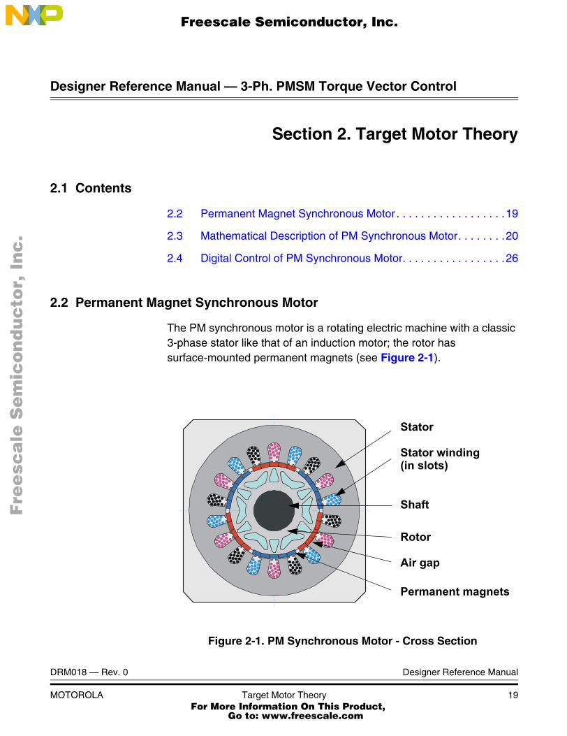
where a and a2 are the spatial operators, a = ej2π/3, a2 = ej4π/3 and k is the transformation constant, chosen as k=2/3. Figure 2-2 shows the stator current space vector projection:
isa isb isc 0=+ +
is k= isa aisb a2isc+ +( )
Fre
esc
ale
Se
mic
on
du
cto
r, I
Freescale Semiconductor, Inc.
For More Information On This Product, Go to: www.freescale.com
nc
...
Target Motor TheoryMathematical Description of PM Synchronous Motor
DRM018 — Rev. 0 Designer Reference Manual
MOTOROLA Target Motor Theory 21
Figure 2-2. Stator Current Space Vector and Its Projection
The space vector defined by (EQ 2-2.) can be expressed utilizing two-axis theory. The real part of the space vector is equal to the instantaneous value of the direct-axis stator current component, isα, and whose imaginary part is equal to the quadrature-axis stator current component, isβ. Thus, the stator current space vector, in the stationary reference frame attached to the stator can be expressed as:
(EQ 2-3.)
In symmetrical three-phase machines, the direct and quadrature axis stator currents isα, isβ are fictitious quadrature-phase (two-phase)
β
i s β
phase- b
is isα jisβ+=
Fre
esc
ale
Se
mic
on
du
cto
r, I
Freescale Semiconductor, Inc.
For More Information On This Product, Go to: www.freescale.com
nc
...

Target Motor Theory
Designer Reference Manual DRM018 — Rev. 0
22 Target Motor Theory MOTOROLA
current components, which are related to the actual three-phase stator currents as follows:
(EQ 2-4.)
(EQ 2-5.)
where k=2/3 is a transformation constant.
The space vectors of other motor quantities (voltages, currents, magnetic fluxes etc.) can be defined in the same way as the stator current space vector.
For a description of the PM synchronous motor, the symmetrical three-phase smooth-air-gap machine with sinusoidally-distributed windings is considered. The voltage equations of stator in the instantaneous form can then be expressed as:
(EQ 2-6.)
(EQ 2-7.)
(EQ 2-8.)
where uSA, uSB and uSC are the instantaneous values of stator voltages, iSA, iSB and iSC are the instantaneous values of stator currents, and ψSA, ψSB, ψSC are instantaneous values of stator flux linkages, in phase SA, SB and SC.
Due to the large number of equations in the instantaneous form, the equations (EQ 2-6.), (EQ 2-7.) and (EQ 2-8.), it is more practical to
isα k isa12---isb� 1
2---isc�
=
isβ k 32
------- isb isc�( )=
uSA RSiSA tdd ψSA+=
uSB RSiSB tdd ψSB+=
uSC RSiSC tdd ψSC+=
Fre
esc
ale
Se
mic
on
du
cto
r, I
Freescale Semiconductor, Inc.
For More Information On This Product, Go to: www.freescale.com
nc
...

Target Motor TheoryMathematical Description of PM Synchronous Motor
DRM018 — Rev. 0 Designer Reference Manual
MOTOROLA Target Motor Theory 23
rewrite the instantaneous equations using two axis theory (Clarke transformation). The PM synchronous motor can be expressed as:
(EQ 2-9.)
(EQ 2-10.)
(EQ 2-11.)
(EQ 2-12.)
(EQ 2-13.)
where:
α,β is the stator orthogonal coordinate system
uSα,β is the stator voltage
iSα,β is the stator current
ΨSα,β is the stator magnetic flux
ΨM is the rotor magnetic flux
RS is the stator phase resistance
LS is the stator phase inductance
ω / ωF is the electrical rotor speed / fields speed
p is the number of poles per phase
J is the inertia
TL is the load torque
Θr is the rotor position in α,β coordinate system
The equations (EQ 2-9.) through (EQ 2-13.) represent the model of PM synchronous motor in the stationary frame α, β fixed to the stator.
Besides the stationary reference frame attached to the stator, motor model voltage space vector equations can be formulated in a general reference frame, which rotates at a general speed ωg. If a general reference frame is used, with direct and quadrature axes x,y rotating at a general instantaneous speed ωg=dθg/dt, as shown in Figure 2-3, where θg is the angle between the direct axis of the stationary reference
uSα RSiSα tdd ΨSα+=
uSβ RSiSβ tdd ΨSβ+=
ΨSα LSiSα ΨM Θr( )cos+=
ΨSβ LSiSβ ΨM Θr( )sin+=
tddω p
J--- 3
2---p ΨSαiSβ ΨSβiSα�( ) TL�=
Fre
esc
ale
Se
mic
on
du
cto
r, I
Freescale Semiconductor, Inc.
For More Information On This Product, Go to: www.freescale.com
nc
...

Target Motor Theory
Designer Reference Manual DRM018 — Rev. 0
24 Target Motor Theory MOTOROLA
frame (α) attached to the stator and the real axis (x) of the general reference frame, then (EQ 2-14.) defines the stator current space vector in general reference frame:
(EQ 2-14.)
Figure 2-3. Application of the General Reference Frame
The stator voltage and flux-linkage space vectors can be similarly obtained in the general reference frame.
Similar considerations hold for the space vectors of the rotor voltages, currents and flux linkages. The real axis (rα) of the reference frame attached to the rotor is displaced from the direct axis of the stator reference frame by the rotor angle θr. Since it can be seen that the angle between the real axis (x) of the general reference frame and the real axis of the reference frame rotating with the rotor (rα) is θg-θr, in the general reference frame, the space vector of the rotor currents can be expressed as:
(EQ 2-15.)
isg isejθg�
isx jisy+==
β
x
y
g
irg irej θg θr�( )�
irx jiry+==
Fre
esc
ale
Se
mic
on
du
cto
r, I
Freescale Semiconductor, Inc.
For More Information On This Product, Go to: www.freescale.com
nc
...

Target Motor TheoryMathematical Description of PM Synchronous Motor
DRM018 — Rev. 0 Designer Reference Manual
MOTOROLA Target Motor Theory 25
where is the space vector of the rotor current in the rotor reference frame.
The space vectors of the rotor voltages and rotor flux linkages in the general reference frame can be similarly expressed.
The motor model voltage equations in the general reference frame can be expressed by utilizing introduced transformations of the motor quantities from one reference frame to the general reference frame. The PM synchronous motor model is often used in vector control algorithms. The aim of vector control is to implement control schemes which produce high dynamic performance and are similar to those used to control DC machines. To achieve this, the reference frames may be aligned with the stator flux-linkage space vector, the rotor flux-linkage space vector or the magnetizing space vector. The most popular reference frame is the reference frame attached to the rotor flux linkage space vector, with direct axis (d) and quadrature axis (q).
After transformation into d-q coordinates, the motor model as follows:
(EQ 2-16.)
(EQ 2-17.)
(EQ 2-18.)
(EQ 2-19.)
(EQ 2-20.)
By considering that below base speed isd=0, the equation (EQ 2-20.) can be reduced to the following form:
(EQ 2-21.)
ir
uSd RSiSd tdd ΨSd ωFΨSq�+=
uSq RSiSq tdd ΨSq ωFΨSd+ +=
ΨSd LSiSd ΨM+=
ΨSq LSiSq=
tddω p
J--- 3
2---p ΨSdiSq ΨSqiSd�( ) TL�=
tddω p
J--- 3
2---p ΨMiSq( ) TL�=
Fre
esc
ale
Se
mic
on
du
cto
r, I
Freescale Semiconductor, Inc.
For More Information On This Product, Go to: www.freescale.com
nc
...

Target Motor Theory
Designer Reference Manual DRM018 — Rev. 0
26 Target Motor Theory MOTOROLA
From the equation (EQ 2-21.), it can be seen that the torque is dependent and can be directly controlled by the current isq only. It is obvious to obtain PM synchornous motor torque eqaution as follwos:
(EQ 2-22.)
2.4 Digital Control of PM Synchronous Motor
Usually the applications of the PM synchronous motors are powered by inverters. The inverter converts DC power to AC power at the required frequency and amplitude. The typical 3-phase inverter is illustrated in Figure 2-4.
Figure 2-4. 3- Phase Inverter
The inverter consists of three half-bridge units where the upper and lower switches are controlled complementarily, meaning when the upper one is turned on, the lower one must be turned off, and vice versa. Because the power device’s turn off time is longer than its turn on time, some deadtime must be inserted between the turn off of one transistor of the half-bridge, and the turn on of its complementary device. The
Te32---p ΨMiSq( )=
Q1
PWM_Q5
Q6Q4
C1
Phase_C
PWM_Q1
PWM_Q4
PWM_Q3
Phase_BGND
Q2
UDCB
PWM_Q2
Phase_A
Q3
PWM_Q6
Q5
Fre
esc
ale
Se
mic
on
du
cto
r, I
Freescale Semiconductor, Inc.
For More Information On This Product, Go to: www.freescale.com
nc
...

Target Motor TheoryDigital Control of PM Synchronous Motor
DRM018 — Rev. 0 Designer Reference Manual
MOTOROLA Target Motor Theory 27
output voltage is mostly created by a pulse width modulation (PWM) technique, where an isosceles triangle carrier wave is compared with a fundamental-frequency sine modulating wave, and the natural points of intersection determine the switching points of the power devices of a half bridge inverter. This technique is shown in Figure 2-5. The 3-phase voltage waves are shifted 120o to each other and, thus, a 3-phase motor can be supplied.
Figure 2-5. Pulse Width Modulation
The most popular power devices for motor control applications are Power MOSFETs and IGBTs.
A Power MOSFET is a voltage-controlled transistor. It is designed for high-frequency operation and has a low voltage drop; thus, it has low power losses. However, the saturation temperature sensitivity limits the MOSFET application in high-power applications.
An insulated-gate bipolar transistor (IGBT) is a bipolar transistor controlled by a MOSFET on its base. The IGBT requires low drive current, has fast switching time, and is suitable for high switching
PWM CarrierWave
GeneratedSine Wave
PWM Output T1(Upper Switch)
01
0
1
PWM Output T2(Lower Switch)
1
0
-1
ωt
ωt
ωt
Fre
esc
ale
Se
mic
on
du
cto
r, I
Freescale Semiconductor, Inc.
For More Information On This Product, Go to: www.freescale.com
nc
...

Target Motor Theory
Designer Reference Manual DRM018 — Rev. 0
28 Target Motor Theory MOTOROLA
frequencies. The disadvantage is the higher voltage drop of a bipolar transistor, causing higher conduction losses.
2.4.1 Vector Control of PM Synchronous Motor
Vector Control is an elegant control method of a PM synchronous motor, where field-oriented theory is used to control space vectors of magnetic flux, current, and voltage. It is possible to set up the coordinate system to decompose the vectors into a magnetic field-generating part and a torque-generating part. The structure of the motor controller (Vector Control controller) is then almost the same as for a separately-excited DC motor, which simplifies the control of PM synchronous motor. This Vector Control technique was developed specifically to achieve a similarly dynamic performance in PM synchronous motors.
As explained in 3.3 Vector Control Drive Concept, there is chosen a torque control with inner current closed-loop, where the rotor flux is considered as zero input.
This method is broken down onto the field-generating and torque-generating parts of the stator current to be able to separately control the magnetic flux and the torque. In order to do so, we need to set up the rotary coordinate system connected to the rotor magnetic field; this system is generally called a “d-q coordinate system”. Very high CPU performance is needed to perform the transformation from rotary to stationary coordinate systems. Therefore, the Motorola DSP56F80x is very well suited for use in a Vector Control algorithm. All transformations which are needed for Vector Control will be described in the next section.
2.4.2 Block Diagram of Vector Control
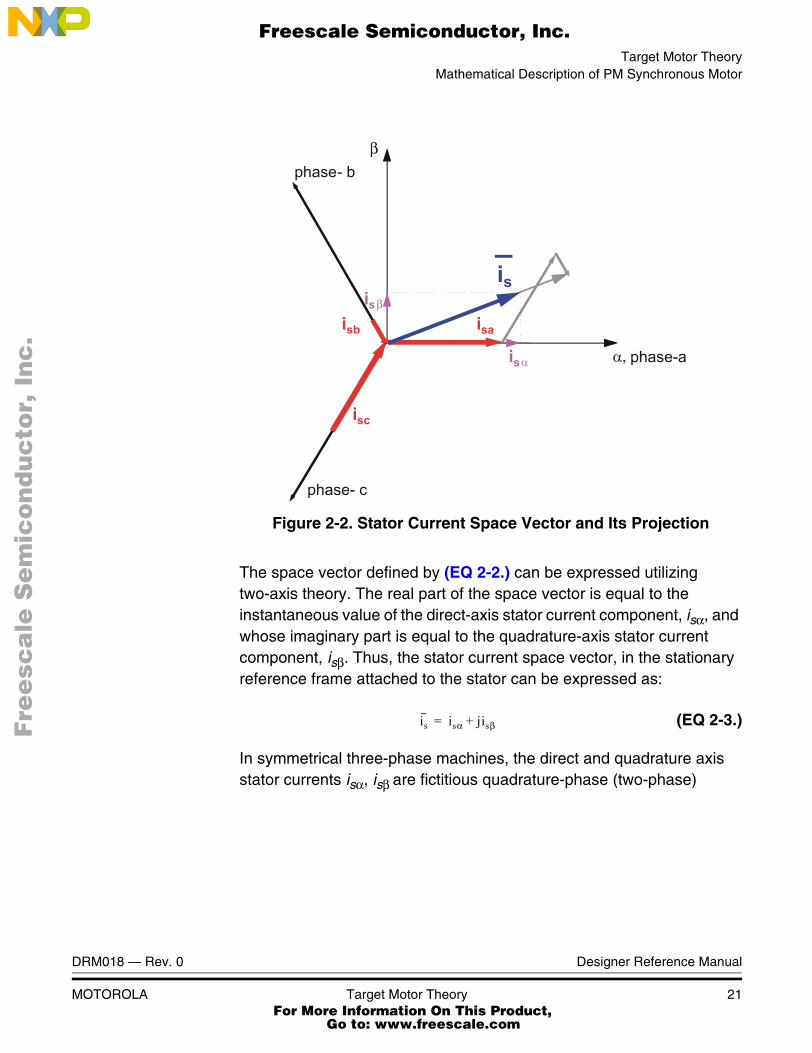
Figure 2-6 shows the basic structure of Vector Control of the PM synchronous motor. To perform Vector Control, follow these steps:
• Measure the motor quantities (phase voltages and currents)
• Transform them into the two-phase system (α,β) using Clarke transformation
• Calculate the rotor flux space vector magnitude and position angle
Fre
esc
ale
Se
mic
on
du
cto
r, I
Freescale Semiconductor, Inc.
For More Information On This Product, Go to: www.freescale.com
nc
...
Target Motor TheoryDigital Control of PM Synchronous Motor
DRM018 — Rev. 0 Designer Reference Manual
MOTOROLA Target Motor Theory 29
• Transform stator currents into the d-q coordinate system using Park transformation
• The stator current torque- (isq) and flux- (isd) producing components are controlled separately by the controllers
• The output stator voltage space vector is calculated using the decoupling block
• The stator voltage space vector is transformed back from the d-q coordinate system into the two-phase system and fixed with the stator by inverse Park transformation
• Using sinewave modulation, the output 3-phase voltage is generated
Figure 2-6. Block Diagram of PM Synchronous Motor Vector Control
2.4.3 Vector Control Transformations
Transforming the PM synchronous motor into a DC motor is based on points of view. As shown in 2.4.2 Block Diagram of Vector Control, a coordinate transformation is required.
3-phase Power Stage
Position/Speed sensor
PMSMmotor
SinewaveGeneration
Forward ClarkeTransformation
Forward ParkTransformation
Dec
oupl
ing
ISβ
ISα
ISq
ISd
U
U
U
U
USd
Sd_lin
Sq_lin
Sα
SβUSq
I
I
I
Sa
Sb
Sc
-
-
Torque Command
Line Input
Position
pwm a
pwm b
pwm c
FluxCommand
Fre
esc
ale
Se
mic
on
du
cto
r, I
Freescale Semiconductor, Inc.
For More Information On This Product, Go to: www.freescale.com
nc
...
Target Motor Theory
Designer Reference Manual DRM018 — Rev. 0
30 Target Motor Theory MOTOROLA
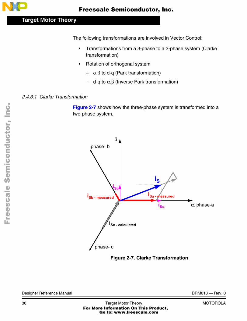
The following transformations are involved in Vector Control:
• Transformations from a 3-phase to a 2-phase system (Clarke transformation)
• Rotation of orthogonal system
– α,β to d-q (Park transformation)
– d-q to α,β (Inverse Park transformation)
2.4.3.1 Clarke Transformation
Figure 2-7 shows how the three-phase system is transformed into a two-phase system.
Figure 2-7. Clarke Transformation
α, phase-a
β
iSα
iSβ
iS
iSa - measurediSb - measured
iSc - calculated
phase- b
phase- c
Fre
esc
ale
Se
mic
on
du
cto
r, I
Freescale Semiconductor, Inc.
For More Information On This Product, Go to: www.freescale.com
nc
...

Target Motor TheoryDigital Control of PM Synchronous Motor
DRM018 — Rev. 0 Designer Reference Manual
MOTOROLA Target Motor Theory 31
To transfer the graphical representation into mathematical language:
(EQ 2-23.)
In most cases, the 3-phase system is symmetrical, which means that the sum of the phase quantities is always zero.
(EQ 2-24.)
The constant “K” can be freely chosen and equalizing the α-quantity and a-phase quantity is recommended. Then:
(EQ 2-25.)
We can fully define the Park-Clarke transformation:
(EQ 2-26.)
2.4.3.2 Transformation from α,β to d-q Coordinates and Backwards
Vector Control is performed entirely in the d-q coordinate system to make the control of PM synchronous motors elegant and easy; see 2.4.2 Block Diagram of Vector Control.
Of course, this requires transformation in both directions and the control action must be transformed back to the motor side.
αβ
K1 1
2---� 1
2---�
0 32
------- 32
-------�
abc
=
α K a 12---b� 1
2---c�
a b c+ + 0= K 32--- a= = =
α a= K 23---=⇒
αβ
23--- 1
3---� 1
3---�
0 13
------- 13
-------�
abc
a b c+ + 0=1 0 0
0 13
------- 13
-------�
abc
= = =
Fre
esc
ale
Se
mic
on
du
cto
r, I
Freescale Semiconductor, Inc.
For More Information On This Product, Go to: www.freescale.com
nc
...
Target Motor Theory
Designer Reference Manual DRM018 — Rev. 0
32 Target Motor Theory MOTOROLA
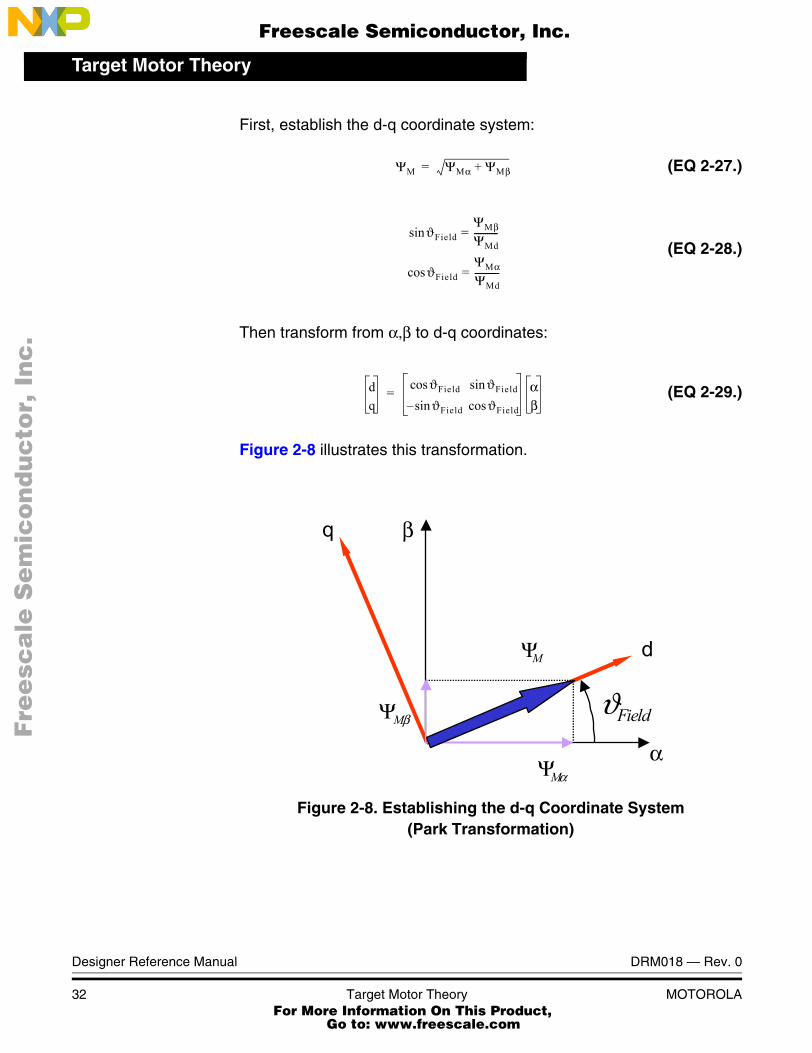
First, establish the d-q coordinate system:
(EQ 2-27.)
(EQ 2-28.)
Then transform from α,β to d-q coordinates:
(EQ 2-29.)
Figure 2-8 illustrates this transformation.
Figure 2-8. Establishing the d-q Coordinate System(Park Transformation)
ΨM ΨMα ΨMβ+=
ϑFieldsinΨMβ
ΨMd-----------=
ϑFieldcosΨMα
ΨMd-----------=
dq
ϑFieldcos ϑFieldsinϑFieldsin� ϑFieldcos
αβ
=
βMΨ ϑField
αMΨ
MΨ
α
βq
d
Fre
esc
ale
Se
mic
on
du
cto
r, I
Freescale Semiconductor, Inc.
For More Information On This Product, Go to: www.freescale.com
nc
...

Target Motor TheoryDigital Control of PM Synchronous Motor
DRM018 — Rev. 0 Designer Reference Manual
MOTOROLA Target Motor Theory 33
The backward (Inverse Park) transformation (from d-q to α,β) is:
(EQ 2-30.)
2.4.4 PMSM Vector Control
This section describes the control regarding the required stator current vectors isd, isq.
There are two speed ranges (shown in Figure 2-9), which differ by controlled current vector:
• Control in Normal Operating Range is a control mode for a speed required below nominal motor speed
• Control in Field-Weakening Range is a control mode for a speed required above nominal motor speed. This application does not utilize control in field-weakening range.
2.4.4.1 Control in Normal Operating Range
Assume an ideal PM synchronous motor with constant stator reluctance, Ls = const. The equations (EQ 2-17.), (EQ 2-18.) and (EQ 2-19.) can then be written as:
(EQ 2-31.)
As demonstrated from PM synchronous motor equations, the maximum efficiency of the ideal PM synchronous motor is obtained when maintaining the current flux-producing component isd at zero. Therefore, in the drive from Figure 2-6, the Field-Weakening Controller sets isd = 0 in the normal operating range. The torque regulator controls the current torque-producing component isq.
A real 3-phase power inverter has voltage and current rating limitations:
1. The absolute value of stator voltage us is physically limited according to DCBus voltage to u_sdq_max limit
αβ
ϑFieldcos ϑFieldsin�ϑFieldsin ϑFieldcos
dq
=
uSq RSiSq LS tdd iSq ωF LSiSd ΨM+( )+ +=
Fre
esc
ale
Se
mic
on
du
cto
r, I
Freescale Semiconductor, Inc.
For More Information On This Product, Go to: www.freescale.com
nc
...
Target Motor Theory
Designer Reference Manual DRM018 — Rev. 0
34 Target Motor Theory MOTOROLA
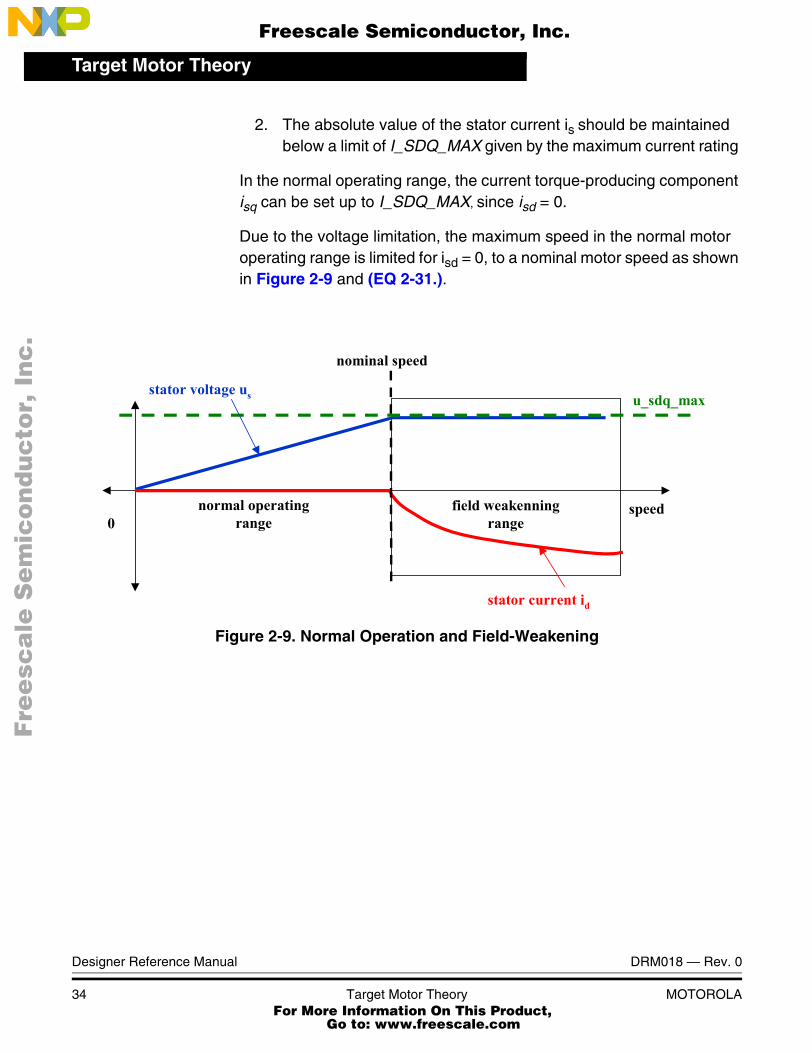
2. The absolute value of the stator current is should be maintained below a limit of I_SDQ_MAX given by the maximum current rating
In the normal operating range, the current torque-producing component isq can be set up to I_SDQ_MAX, since isd = 0.
Due to the voltage limitation, the maximum speed in the normal motor operating range is limited for isd = 0, to a nominal motor speed as shown in Figure 2-9 and (EQ 2-31.).
Figure 2-9. Normal Operation and Field-Weakening
field weakenningrange
speed
nominal speed
stator voltage us
stator current id
u_sdq_max
0normal operating
range
Fre
esc
ale
Se
mic
on
du
cto
r, I
Freescale Semiconductor, Inc.
For More Information On This Product, Go to: www.freescale.com
nc
...

DRM018 — Rev. 0 Designer Reference Manual
MOTOROLA System Description 35
Designer Reference Manual — 3-Ph. PMSM Torque Vector Control
Section 3. System Description
3.1 Contents
3.2 System Specification . . . . . . . . . . . . . . . . . . . . . . . . . . . . . . . .35
3.3 Vector Control Drive Concept . . . . . . . . . . . . . . . . . . . . . . . . . .36
3.4 System Blocks Concept . . . . . . . . . . . . . . . . . . . . . . . . . . . . . .39
3.2 System Specification
The motor control system is designed to drive a 3-phase PM synchronous motor in a closed-loop of torque-generating part of current isq. The application meets the following performance specifications:
• Torque vector control of PM motor using the quadrature encoder as a position sensor
• Targeted for DSP56F805EVM
• Running on a 3-phase Low-volatge PM synchronous motor control development platform at 12 DC
• Control technique incorporates:
– Vector Control with torque-generating part of current isq
– Rotation in both directions
– Motoring and generator mode with brake
– Start from any motor position with rotor alignment
• Manual interface (Start/Stop switch, Up/Down push button control, LED indicator)
• PC master software control interface (motor start/stop, speed set-up)
Fre
esc
ale
Se
mic
on
du
cto
r, I
Freescale Semiconductor, Inc.
For More Information On This Product, Go to: www.freescale.com
nc
...

System Description
Designer Reference Manual DRM018 — Rev. 0
36 System Description MOTOROLA
• PC master software remote monitor
• Power stage board identification
• Overvoltage, undervoltage, overcurrent and overheating fault protection
The PM synchronous drive introduced here is designed to power a high-voltage PM synchronous motor with a quadrature encoder. It has the following specifications:
3.3 Vector Control Drive Concept
A standard system concept is used with this drive; see Figure 3-1. The system incorporates the following hardware parts:
• Three-phase PM synchronous motor high-voltage development platform
• Feedback sensors for:
– Position (quadrature encoder)
– DCBus voltage
Table 3-1. High Voltage Hardware Set Specifications
Motor Characteristics:
Motor Type6 poles, 3-phase, star
connected, BLDC motor
Speed Range 3000 rpm (at 12V)
Maximum Electrical Power: 150 W
Phase Voltage 3*6.5 V
Phase Current 17 A
Drive Characteristics:
Speed Range < 3000 rpm
Input Voltage 12V DC
Maximum DCBus Voltage 15.8 V
Control Algorithm Torque Closed-Loop Control
Optoisolation Required
Fre
esc
ale
Se
mic
on
du
cto
r, I
Freescale Semiconductor, Inc.
For More Information On This Product, Go to: www.freescale.com
nc
...

System DescriptionVector Control Drive Concept
DRM018 — Rev. 0 Designer Reference Manual
MOTOROLA System Description 37
– Phase currents
– DCBus overcurrent detection
– Temperature
• The DSP56F805 evaluation module
The drive can be controlled in two different operational modes:
In the Manual operational mode, the required speed is set by the Start/Stop switch and the Up/Down push buttons.
In the PC master software operational mode, the required speed and Start/Stop switch are set by the PC.
Figure 3-1. Drive Concept
Fre
esc
ale
Se
mic
on
du
cto
r, I
Freescale Semiconductor, Inc.
For More Information On This Product, Go to: www.freescale.com
nc
...

System Description
Designer Reference Manual DRM018 — Rev. 0
38 System Description MOTOROLA
The control process is as follows:
When the Start command is accepted (using the Start/Stop Switch or PC master software command), the required torque generating part of current is calculated according to the Up/Down push buttons or PC master software commands. The required torque generating part of current reference command is put to the current controller. The comparison between the required torque generating part of current command and the actual measured current generates a current error. Based on the error, the current controller generates a volatge, Us_qReq. A second part of stator current Is_dReq, which corresponds to flux might be given by the Field-Weakening Controller but in this application is considered as zero current. Simultaneously, the stator currents Is_a, Is_b, and Is_c are measured and transformed from instantaneous values into the stationary reference frame α, β, and consecutively into the rotary reference frame d-q (Park - Clarke transformation). Based on the errors between required and actual currents in the rotary reference frame, the current controllers generate output voltages Us_q and Us_d (in the rotary reference frame d-q). The voltages Us_q and Us_d are transformed back into the stationary reference frame α, β and, after DCBus ripple elimination, are recalculated to the 3-phase voltage system, which is applied to the motor. The actual speed is calculated from the pulses of the quadrature encoder.
Beside the main control loop, the DCBus voltage, DCBus current and power stage temperature are measured during the control process. They are used for overvoltage, undervoltage, overcurrent and overheating protection of the drive. The undervoltage and overheating protection is performed by software, while the overcurrent and overvoltage fault signal utilizes a fault input of the DSP.
If any of the previously-mentioned faults occur, the motor control PWM outputs are disabled in order to protect the drive, and the fault state of the system is displayed by the on-board LED.
A hardware error is also detected if the wrong power stage is used. Each power stage contains a simple module generating a logic sequence unique for that type of power stage. During chip initialization, this sequence is read and evaluated according to the decoding table. If the correct power stage is identified, the program can continue. In the case
Fre
esc
ale
Se
mic
on
du
cto
r, I
Freescale Semiconductor, Inc.
For More Information On This Product, Go to: www.freescale.com
nc
...

System DescriptionSystem Blocks Concept
DRM018 — Rev. 0 Designer Reference Manual
MOTOROLA System Description 39
of wrong hardware, the program stays in an infinite loop, displaying the fault condition.
3.4 System Blocks Concept
3.4.1 Position and Speed Sensing
All members of Motorola’s DSP56F80x family, except the DSP56F801 device , have a quadrature decoder. This peripheral is commonly used for position and speed sensing. The quadrature decoder position counter counts up/down each edge of Phase A and Phase B signals according to their order. On each revolution, the position counter is cleared by an index pulse; see Figure 3-2.
Figure 3-2. Quadrature Encoder Signals
This means that the zero position is linked with the index pulse, but Vector Control requires the zero position, where the rotor is aligned to the d axis; see 3.4.1.4 Position Reset with Rotor Alignment. Therefore, using a quadrature decoder to decode the encoder’s signal requires either the calculation of an offset which aligns the quadrature decoder position counter with the aligned rotor position (zero position), or the coupling of the zero rotor position with the index pulse of a quadrature encoder. To avoid the calculation of the rotor position offset, the quadrature decoder is not used in this application. The decoder’s digital processing capabilities are then free to be used by another application and the application presented can then run on the DSP56F801, which lacks a quadrature decoder.
Fre
esc
ale
Se
mic
on
du
cto
r, I
Freescale Semiconductor, Inc.
For More Information On This Product, Go to: www.freescale.com
nc
...
System Description
Designer Reference Manual DRM018 — Rev. 0
40 System Description MOTOROLA
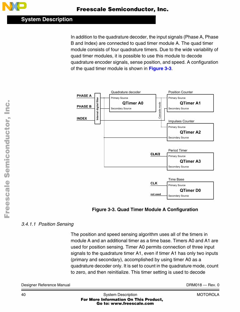
In addition to the quadrature decoder, the input signals (Phase A, Phase B and Index) are connected to quad timer module A. The quad timer module consists of four quadrature timers. Due to the wide variability of quad timer modules, it is possible to use this module to decode quadrature encoder signals, sense position, and speed. A configuration of the quad timer module is shown in Figure 3-3.
Figure 3-3. Quad Timer Module A Configuration
3.4.1.1 Position Sensing
The position and speed sensing algorithm uses all of the timers in module A and an additional timer as a time base. Timers A0 and A1 are used for position sensing. Timer A0 permits connection of three input signals to the quadrature timer A1, even if timer A1 has only two inputs (primary and secondary), accomplished by using timer A0 as a quadrature decoder only. It is set to count in the quadrature mode, count to zero, and then reinitialize. This timer setting is used to decode
Fre
esc
ale
Se
mic
on
du
cto
r, I
Freescale Semiconductor, Inc.
For More Information On This Product, Go to: www.freescale.com
nc
...

System DescriptionSystem Blocks Concept
DRM018 — Rev. 0 Designer Reference Manual
MOTOROLA System Description 41
quadrature signals only. Timer A1 is connected to timer A0 in cascade mode. In this mode, the information about counting up/down is connected internally to timer A1; thus, the secondary input of timer A1 is free to be used for the index pulse. The counter A1 is set to count to +/- ((4*number of pulses per revolution) - 1) and reinitialize after compare. The value of the timer A1 corresponds to the rotor position.
The position of the index pulse is sensed to avoid the loss of some pulses under the influence of noise during extended motor operation, which can result in incorrect rotor position sensing. If some pulses are lost, a different position of the index pulse is detected, and a position sensing error is signaled. If a check of the index pulse is not required, timer A1 can be removed and timer A0 set as the position counter A1. The resulting value of timer A1 is scaled to range <-1; 1), which corresponds to <-π; π).
3.4.1.2 Speed Sensing
There are two common ways to measure speed. The first method measures the time between two following edges of quadrature encoder, and the second method measures a position difference (a number of pulses) per constant period. The first method is used at low speed. At the moment when the measured period is very short, the speed calculation algorithm switches to the second method.
The proposed algorithm combines both methods. The algorithm simultaneously measures the number of quadrature encoder pulses per constant period, and an accurate time interval between the first and last pulse is counted during that constant period. The speed can then be expressed as:
(EQ 3-1.)
where:
speed alculated speed
k scaling constant
N number of pulses per constant period
speed k N⋅T
-----------=
Fre
esc
ale
Se
mic
on
du
cto
r, I
Freescale Semiconductor, Inc.
For More Information On This Product, Go to: www.freescale.com
nc
...

System Description
Designer Reference Manual DRM018 — Rev. 0
42 System Description MOTOROLA
T accurate period of N pulses
The algorithm requires two timers for counting pulses and measuring their period, and a third timer as a time base; see Figure 3-3. Timer A2 counts the pulses of the quadrature encoder, and timer A3 counts a system clock divided by 2. The values in both timers can be captured by each edge of the Phase A signal. The time base is provided by timer D0, which is set to call the speed processing algorithm every 900µs. An explanation of how the speed processing algorithm works follows.
First, the new captured values of both timers are read. The difference in the number of pulses and their accurate time interval are calculated from actual and previous values. The new values are then saved for the next period, and the capture register is enabled. From that moment, the first edge of Phase A signal captures the values of both timers (A2, A3) and the capture register is disabled. This process is repeated on each call of the speed processing algorithm; see Figure 3-4.
Figure 3-4. Speed Processing
Fre
esc
ale
Se
mic
on
du
cto
r, I
Freescale Semiconductor, Inc.
For More Information On This Product, Go to: www.freescale.com
nc
...

System DescriptionSystem Blocks Concept
DRM018 — Rev. 0 Designer Reference Manual
MOTOROLA System Description 43
3.4.1.3 Minimum and Maximum Speed Calculation
The minimum speed is calculated with the following equation:
(EQ 3-2.)
where:
ωmin Minimum obtainable speed [rpm]
N Number of pulses per revolution [1/rev]
Tcalc Period of speed measurement (calculation period) [s]
In the application, the quadrature encoder has 1024 pulses per revolution and a calculation period of 900µs was chosen on the basis of a motor mechanical constant. Thus, (EQ 3-2.) calculates the minimum speed as 16.3 rpm.
The maximum speed can be expressed as:
(EQ 3-3.)
where:
ωmax Maximum obtainable speed [rpm]
N Number of pulses per revolution [1/rev]
TclkT2 Period of input clock to timer A2 [s]
Substitution in (EQ 3-3.) for N and TclkT2 (timer A2 input clock = system clock 36 MHz/2) yields a maximum speed of 263672rpm. As demonstrated, the algorithm can measure speed across a wide range. Because such high speed is not practical, the maximum speed can be reduced to a required range by the constant k in (EQ 3-1.). The constant k can be calculated as:
(EQ 3-4.)
where:
ωmin60
4NTcalc-------------------=
ωmax60
4NTclkT2-----------------------=
k 604NTclkT2ωmax-----------------------------------=
Fre
esc
ale
Se
mic
on
du
cto
r, I
Freescale Semiconductor, Inc.
For More Information On This Product, Go to: www.freescale.com
nc
...

System Description
Designer Reference Manual DRM018 — Rev. 0
44 System Description MOTOROLA
k Scaling constant in (EQ 3-1.)
ωmax Maximum of the speed range [rpm]
N Number of pulses per revolution [1/rev]
TclkT2 Period of input clock to timer A2 [s]
In this application, the maximum measurable speed is limited to 6000rpm.
NOTE: To ensure an accurate speed calculation, you must choose the input clock of timer A2 so that the calculation period of speed processing (in this case, 900µs) is represented in timer A2 as a value lower than 0x7FFFH (900.10-6/TclkT2<=0x7FFFH).
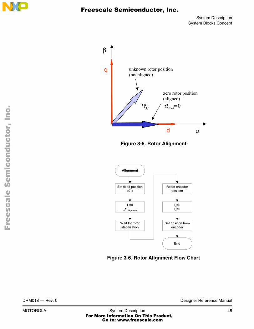
3.4.1.4 Position Reset with Rotor Alignment
After reset, the rotor position is unknown, because a quadrature encoder does not give an absolute position until the index pulse arrives. As shown in Figure 3-5, the rotor position must be aligned with the d axis of the d-q coordinate system before a motor begins running. The alignment algorithm is shown in Figure 3-6. First, the position is set to zero, independent of the actual rotor position. (The value of the quadrature encoder does not affect this setting). Then the Id current is set to alignment current. The rotor is now aligned to the required position. After rotor stabilization, the encoder is reset to the zero position, then the Id current is set back to zero, and alignment is finished. The alignment is executed only once during the first transition from the Stop to Run state of the Run/Stop switch.
Fre
esc
ale
Se
mic
on
du
cto
r, I
Freescale Semiconductor, Inc.
For More Information On This Product, Go to: www.freescale.com
nc
...
System DescriptionSystem Blocks Concept
DRM018 — Rev. 0 Designer Reference Manual
MOTOROLA System Description 45
Figure 3-5. Rotor Alignment
Figure 3-6. Rotor Alignment Flow Chart
0=FieldϑMΨ
α
β
q
d
unknown rotor position(not aligned)
zero rotor position(aligned)
Alignment
Set fixed position(0°)
Iq=0Id=IAlignment
Wait for rotorstabilization
Set position fromencoder
Iq=0Id=0
End
Reset encoderposition
Fre
esc
ale
Se
mic
on
du
cto
r, I
Freescale Semiconductor, Inc.
For More Information On This Product, Go to: www.freescale.com
nc
...
System Description
Designer Reference Manual DRM018 — Rev. 0
46 System Description MOTOROLA
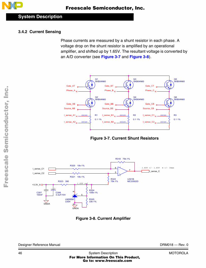
3.4.2 Current Sensing
Phase currents are measured by a shunt resistor in each phase. A voltage drop on the shunt resistor is amplified by an operational amplifier, and shifted up by 1.65V. The resultant voltage is converted by an A/D converter (see Figure 3-7 and Figure 3-8).
Figure 3-7. Current Shunt Resistors
Figure 3-8. Current Amplifier
Q5SKB04N60
Gate_CB
Q4SKB04N60
Phase_A Phase_B
Gate_BB
Source_AB
I_sense_B2
Q1SKB04N60
Gate_AB
I_sense_C2
I_sense_C1
I_sense_A2
sense
sense
R2
0.1 1%
Phase_C
Q3SKB04N60
I_sense_B1
Gate_CT
sense
sense
R3
0.1 1%
I_sense_A1
Gate_AT Gate_BT
Source_CB
sense
sense
R1
0.1 1%
Q2SKB04N60
Q6SKB04N60
Source_BB
R321 10k-1%
+
C3063.3uF/10V
I_sense_C1
C307100nF
+3.3V_A 1.65V ref
GNDAU304LM285M
8
5
4
R320 10k-1%
R323 390
R318 75k-1%
R32533k-1%
1.65V +/- 1.65V @ +/- Imax
R324100k-1%
+
-
U301BMC33502D
5
67 I_sense_C
I_sense_C2
GNDA
R32275k-1%
Fre
esc
ale
Se
mic
on
du
cto
r, I
Freescale Semiconductor, Inc.
For More Information On This Product, Go to: www.freescale.com
nc
...

System DescriptionSystem Blocks Concept
DRM018 — Rev. 0 Designer Reference Manual
MOTOROLA System Description 47
As shown in Figure 3-7, the currents cannot be measured at any moment. For example, the current flows through Phase A (and shunt resistor R1) only if transistor Q2 is switched on. Likewise, the current in Phase B can be measured if transistor Q4 is switched on, and the current in Phase C can be measured if transistor Q6 is switched on. To get a moment of current sensing, a voltage shape analysis must be done.
The voltage shapes of two different PWM periods are shown in Figure 3-11. The voltage shapes correspond to center-aligned PWM sinewave modulation. As shown, the best moment of current sampling is in the middle of the PWM period, where all bottom transistors are switched on.
To set the exact moment of sampling, the DSP56F80x family offers the ability to synchronize ADC and PWM modules via the SYNC signal. This exceptional hardware feature, patented by Motorola, is used for current sensing. The PWM outputs a synchronization pulse, which is connected as an input to the synchronization module TC2 (Quad Timer C, counter/timer 2). A high-true pulse occurs for each reload of the PWM, regardless of the state of the LDOK bit. The intended purpose of TC2 is to provide a user-selectable delay between the PWM SYNC signal and the updating of the ADC values. A conversion process can be initiated by the SYNC input, which is an output of TC2. The time diagram of the automatic synchronization between PWM and ADC is shown in Figure 3-9.
Fre
esc
ale
Se
mic
on
du
cto
r, I
Freescale Semiconductor, Inc.
For More Information On This Product, Go to: www.freescale.com
nc
...

System Description
Designer Reference Manual DRM018 — Rev. 0
48 System Description MOTOROLA
Figure 3-9. Time Diagram of PWM and ADC Synchronization
However, all three currents cannot be measured from one voltage shape. The PWM period II in Figure 3-11 shows a moment when the bottom transistor of Phase A is switched on for a very short time. If the on-time is shorter than a critical time, the current can not be accurately measured. The critical time is given by hardware configuration (transistor commutation times, response delays of the processing
PWM COUNTER
PWM SYNC
PWMGENERATOR
OUTPUTS 0, 1
PWM
PINS 0, 1
POWER
STAGE
VOLTAGE
TC2
t1
t2
COUNTER
TC2OUTPUT
ADCCONVERSION
ADCISR
dead-time/2
dead-time dead-time
dead-time/2
Fre
esc
ale
Se
mic
on
du
cto
r, I
Freescale Semiconductor, Inc.
For More Information On This Product, Go to: www.freescale.com
nc
...

System DescriptionSystem Blocks Concept
DRM018 — Rev. 0 Designer Reference Manual
MOTOROLA System Description 49
electronics, etc.). Therefore, only two currents are measured and a third current is calculated from the following equation:
(EQ 3-5.)
Figure 3-10. Voltage Shapes of Two Different PWM Periods
0 iA iB iC+ +=
PHASE_A
PHASE_B
PHASE_C
PWM PERIOD
ADC sampling pointcritical pulse width
PWM RELOAD
I. II.
Fre
esc
ale
Se
mic
on
du
cto
r, I
Freescale Semiconductor, Inc.
For More Information On This Product, Go to: www.freescale.com
nc
...

System Description
Designer Reference Manual DRM018 — Rev. 0
50 System Description MOTOROLA
Figure 3-11. 3-phase Sinewave Voltages and CorrespondingSector Value
A decision must now be m ade about which phase current should be calculated. The simplest technique is to calculate the current of the most positive voltage phase. For example, Phase A generates the most positive voltage within section 0 - 60°, Phase B within section 60° - 120°, and so on; see Figure 3-11.
In this case, the output voltages are divided into six sectors, as shown in Figure 3-11. The current calculation is then made according to the actual sector value.
Sectors 1 and 6:
(EQ 3-6.)
Sectors 2 and 3:
(EQ 3-7.)
0 60 120 180 240 300 3600
0.2
0.4
0.6
0.8
1
Phase APhase BPhase C
angle
duty
cyc
le ra
tios
0 60 120 180 240 300 3600 60 120 180 240 300 3600
0.2
0.4
0.6
0.8
1
0
0.2
0.4
0.6
0.8
1
Phase APhase BPhase C
Phase APhase BPhase C
angle
duty
cyc
le ra
tios
Sector 1 Sector 2 Sector 3 Sector 4 Sector 5 Sector 6Sector 1 Sector 2 Sector 3 Sector 4 Sector 5 Sector 6
II. I.
iA iB� iC�=
iB iA� iC�=
Fre
esc
ale
Se
mic
on
du
cto
r, I
Freescale Semiconductor, Inc.
For More Information On This Product, Go to: www.freescale.com
nc
...

System DescriptionSystem Blocks Concept
DRM018 — Rev. 0 Designer Reference Manual
MOTOROLA System Description 51
Sectors 4 and 5:
(EQ 3-8.)
NOTE: The sector value is used for current calculation only, and has no other meaning in the sinewave modulation. But if we use any type of space vector modulation, we can get the sector value as part of space vector calculation.
3.4.3 Voltage Sensing
The DCBus voltage sensor is represented by a simple voltage divider. The DCBus voltage does not change rapidly. It is nearly constant, with the ripple given by the power supply structure. If a bridge rectifier is used for rectification of the AC line voltage, the ripple frequency is twice the AC line frequency. If the power stage is designed correctly, the ripple amplitude should not exceed 10% of the nominal DCBus value.
The measured DCBus voltage must be filtered to eliminate noise. One of the easiest and fastest techniques is the first order filter, which calculates the average filtered value recursively from the last two samples and coefficient C:
(EQ 3-9.)
To speed up the initialization of the voltage sensing (the filter has exponential dependency with constant of 1/N samples), the moving average filter, which calculates the average value from the last N samples, can be used for initialization:
(EQ 3-10.)
3.4.4 Power Module Temperature Sensing
The measured power module temperature is used for thermal protection The hardware realization is shown in Figure 3-12. The circuit consists of four diodes connected in series, a bias resistor, and a noise suppression
iC iB� iA�=
uDCBusFilt n 1+( ) CuDCBusFilt n 1+( ) CuDCBusFilt n( )�( ) u� DCBusFilt n( )=
uDCBusFilt uDCBus n( )n 1=
N�
∑=
Fre
esc
ale
Se
mic
on
du
cto
r, I
Freescale Semiconductor, Inc.
For More Information On This Product, Go to: www.freescale.com
nc
...

System Description
Designer Reference Manual DRM018 — Rev. 0
52 System Description MOTOROLA
capacitor. The four diodes have a combined temperature coefficient of 8.8 mV/οC. The resulting signal, Temp_sense, is fed back to an A/D input, where software can be used to set safe operating limits. In this application, the temperature, in Celsius, is calculated according to the conversion equation:
(EQ 3-11.)
where:
temp Power module temperature in centigrades
Temp_senseVoltage drop on the diodes, which is measured by ADC [V]
a Diodes-dependent conversion constant
b Diodes-dependent conversion constant
Figure 3-12. Temperature Sensing
temp Temp_sense b�a--------------------------------------=
C1100nF
D1BAV99LT1
R12.2k - 1%
D2BAV99LT1
Temp_sense
+3.3V_A
Fre
esc
ale
Se
mic
on
du
cto
r, I
Freescale Semiconductor, Inc.
For More Information On This Product, Go to: www.freescale.com
nc
...

DRM018 — Rev. 0 Designer Reference Manual
MOTOROLA Hardware Design 53
Designer Reference Manual — 3-Ph. PMSM Torque Vector Control
Section 4. Hardware Design
4.1 Contents
4.2 Hardware Set-up. . . . . . . . . . . . . . . . . . . . . . . . . . . . . . . . . . . .53
4.3 DSP56F805EVM Controller Board . . . . . . . . . . . . . . . . . . . . . .55
4.4 3-Ph BLDC Low Voltage Power Stage . . . . . . . . . . . . . . . . . . .57
4.5 Motor-Brake Specifications. . . . . . . . . . . . . . . . . . . . . . . . . . . .59
4.6 Hardware Documentation . . . . . . . . . . . . . . . . . . . . . . . . . . . . .60
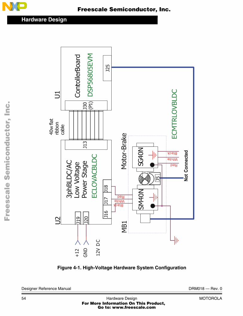
4.2 Hardware Set-up
The application can run on Motorola’s motor control DSPs using the DSP56F803EVM, DSP56F805EVM, or DSP56F807EVM, Motorola’s 3-Phase AC/BLDC high voltage power stage and the BLDC high voltage motor with a quadrature encoder and integrated brake. All components are an integral part of Motorola’s embedded motion control development tools. Application hardware set-up is shown in Figure 4-1.
Fre
esc
ale
Se
mic
on
du
cto
r, I
Freescale Semiconductor, Inc.
For More Information On This Product, Go to: www.freescale.com
nc
...
Hardware Design
Designer Reference Manual DRM018 — Rev. 0
54 Hardware Design MOTOROLA
Figure 4-1. High-Voltage Hardware System Configuration
Fre
esc
ale
Se
mic
on
du
cto
r, I
Freescale Semiconductor, Inc.
For More Information On This Product, Go to: www.freescale.com
nc
...

Hardware DesignDSP56F805EVM Controller Board
DRM018 — Rev. 0 Designer Reference Manual
MOTOROLA Hardware Design 55
All system parts are supplied and documented in these references:
• U1 - DSP56F805 Controller Board for the:
– Supplied as DSP56F805EVM
– Described in the DSP56F805 Evaluation Module Hardware User’s Manual
• U2 - 3-phase AC/BLDC Low-Voltage Power Stage
– Described in the 3-phase Brushless DC Low Voltage Power Stage Manual
• Supplied in a kit with the 3-phase AC/BLDC Low Voltage Power Stage (Order #ECLOVACBLDC)
• MB1 Motor-Brake SM40V + SG40N
– Supplied as Order #ECMTRLOVBLDC
NOTE: The application software is targeted for a PM synchronous motor with sinewave Back-EMF shape. In this demo application, a BLDC motor is used instead, due to the availability of the BLDC motor (MB1). Although the Back-EMF shape of this motor is not an ideal sinewave, it can be controlled by the application software. The drive parameters will be ideal with a PMSM motor with an exact sinewave Back-EMF shape.
A detailed description of the individual board can be found in the appropriate DSP56F80x Evaluation Module User’s Manual, or on the Motorola web site, http://www.motorola.com. The User’s Manual includes the schematic of the board, description of individual function blocks, and a bill of materials. The individual boards can be ordered from Motorola as standard products.
4.3 DSP56F805EVM Controller Board
The DSP56F805EVM is used to demonstrate the abilities of the DSP56F805 and to provide a hardware tool allowing the development of applications that use the DSP56F805.
The DSP56F805EVM is an evaluation module board that includes a DSP56F805 part, peripheral expansion connectors, external memory
Fre
esc
ale
Se
mic
on
du
cto
r, I
Freescale Semiconductor, Inc.
For More Information On This Product, Go to: www.freescale.com
nc
...
Hardware Design
Designer Reference Manual DRM018 — Rev. 0
56 Hardware Design MOTOROLA
and a CAN interface. The expansion connectors are for signal monitoring and user feature expandability.
The DSP56F805EVM is designed for the following purposes:
• Allowing new users to become familiar with the features of the 56800 architecture. The tools and examples provided with the DSP56F805EVM facilitate evaluation of the feature set and the benefits of the family.
• Serving as a platform for real-time software development. The tool suite enables the user to develop and simulate routines, download the software to on-chip or on-board RAM, run it, and debug it using a debugger via the JTAG/OnCETM port. The breakpoint features of the OnCE port enable the user to easily specify complex break conditions and to execute user-developed software at full-speed, until the break conditions are satisfied. The ability to examine and modify all user accessible registers, memory and peripherals through the OnCE port greatly facilitates the task of the developer.
• Serving as a platform for hardware development. The hardware platform enables the user to connect external hardware peripherals. The on-board peripherals can be disabled, providing the user with the ability to reassign any and all of the DSP's peripherals. The OnCE port's unobtrusive design means that all of the memory on the board and on the DSP chip are available to the user.
The DSP56F805EVM provides the features necessary for a user to write and debug software, demonstrate the functionality of that software and interface with the customer's application-specific device(s). The DSP56F805EVM is flexible enough to allow a user to fully exploit the DSP56F805's features to optimize the performance of their product, as shown in Figure 4-2.
Fre
esc
ale
Se
mic
on
du
cto
r, I
Freescale Semiconductor, Inc.
For More Information On This Product, Go to: www.freescale.com
nc
...

Hardware Design3-Ph BLDC Low Voltage Power Stage
DRM018 — Rev. 0 Designer Reference Manual
MOTOROLA Hardware Design 57
Figure 4-2. Block Diagram of the DSP56F805EVM
4.4 3-Ph BLDC Low Voltage Power Stage
Motorola’s embedded motion control series low-voltage (LV) brushless DC (BLDC) power stage is designed to run 3-ph. BLDC and PM Synchronous motors. It operates from a nominal 12-volt motor supply, and delivers up to 30 amps of rms motor current from a dc bus that can deliver peak currents up to 46 amps. In combination with one of Motorola’s embedded motion control series control boards, it provides a software development platform that allows algorithms to be written and tested, without the need to design and build a power stage. It supports a wide variety of algorithms for controlling BLDC motors and PM Synchronous motors.
DSP56F805
RESET
MODE/IRQ
Address,Data &Control
JTAG/OnCE
XTAL/EXTAL
SPI
SCI #0
SCI #1
CAN
TIMER
GPIO
PWM #1
A/D
PWM #2
3.3 V & GND
Peripheral Expansion
Connector(s)
RESETLOGIC
MODE/IRQLOGIC
Program Memory64Kx16-bit
Memory Expansion
Connector(s)
JTAGConnector
ParallelJTAG
Interface
Low FreqCrystal
DSub25-Pin
Data Memory64Kx16-bit
DSub9-Pin
CAN Interface
Debug LEDs
PWM LEDs
Over V Sense
Over I Sense
Zero Crossing Detect
SecondaryUNI-3
PrimaryUNI-3
RS-232Interface
4-Channel10-bit D/A
Power Supply3.3V, 5.0V & 3.3VA
Fre
esc
ale
Se
mic
on
du
cto
r, I
Freescale Semiconductor, Inc.
For More Information On This Product, Go to: www.freescale.com
nc
...

Hardware Design
Designer Reference Manual DRM018 — Rev. 0
58 Hardware Design MOTOROLA
Input connections are made via 40-pin ribbon cable connector J13. Power connections to the motor are made with fast-on connectors J16, J17, and J18. They are located along the back edge of the board, and are labeled Phase A, Phase B, and Phase C. Power requirements are met with a 12-volt power supply that has a 10- to 16-volt tolerance. Fast-on connectors J19 and J20 are used for the power supply. J19 is labeled +12V and is located on the back edge of the board. J20 is labeled 0V and is located along the front edge. Current measuring circuitry is set up for 50 amps full scale. Both bus and phase leg currents are measured. A cycle by cycle overcurrent trip point is set at 46 amps.
The LV BLDC power stage has both a printed circuit board and a power substrate. The printed circuit board contains MOSFET gate drive circuits, analog signal conditioning, low-voltage power supplies, and some of the large passive power components. This board also has a 68HC705JJ7 microcontroller used for board configuration and identification. All of the power electronics that need to dissipate heat are mounted on the power substrate. This substrate includes the power MOSFETs, brake resistors, current-sensing resistors, bus capacitors, and temperature sensing diodes. Figure 4-3 shows a block diagram.
Figure 4-3. Block Diagram
POWERINPUT BIAS
POWERBRAKE
MOSFET
GATE
PHASE CURRENTPHASE VOLTAGE
BUS CURRENTBUS VOLTAGE
MONITOR
ZERO CROSSBACK-EMF SENSE
BOARDID BLOCK
SIGNALSTO/FROMCONTROL
BOARD
POWER MODULE
DRIVERS MOTORTO
Fre
esc
ale
Se
mic
on
du
cto
r, I
Freescale Semiconductor, Inc.
For More Information On This Product, Go to: www.freescale.com
nc
...
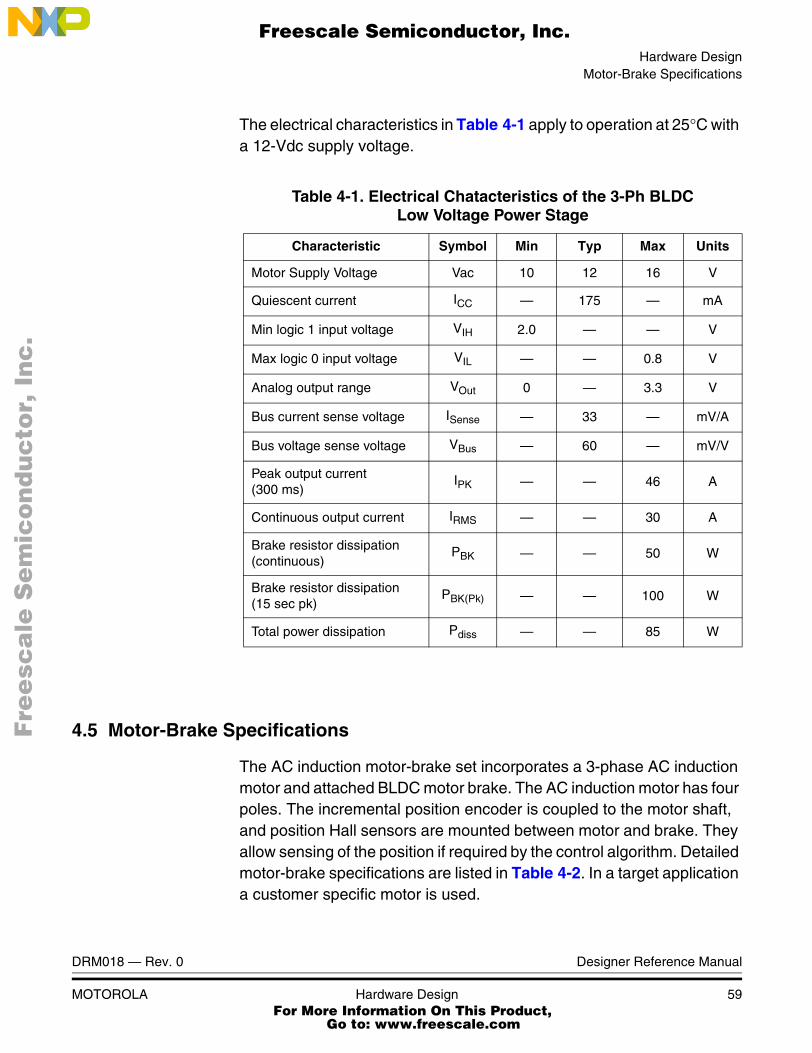
Hardware DesignMotor-Brake Specifications
DRM018 — Rev. 0 Designer Reference Manual
MOTOROLA Hardware Design 59
The electrical characteristics in Table 4-1 apply to operation at 25°C with a 12-Vdc supply voltage.
4.5 Motor-Brake Specifications
The AC induction motor-brake set incorporates a 3-phase AC induction motor and attached BLDC motor brake. The AC induction motor has four poles. The incremental position encoder is coupled to the motor shaft, and position Hall sensors are mounted between motor and brake. They allow sensing of the position if required by the control algorithm. Detailed motor-brake specifications are listed in Table 4-2. In a target application a customer specific motor is used.
Table 4-1. Electrical Chatacteristics of the 3-Ph BLDCLow Voltage Power Stage
Characteristic Symbol Min Typ Max Units
Motor Supply Voltage Vac 10 12 16 V
Quiescent current ICC — 175 — mA
Min logic 1 input voltage VIH 2.0 — — V
Max logic 0 input voltage VIL — — 0.8 V
Analog output range VOut 0 — 3.3 V
Bus current sense voltage ISense — 33 — mV/A
Bus voltage sense voltage VBus — 60 — mV/V
Peak output current(300 ms)
IPK — — 46 A
Continuous output current IRMS — — 30 A
Brake resistor dissipation (continuous)
PBK — — 50 W
Brake resistor dissipation (15 sec pk)
PBK(Pk) — — 100 W
Total power dissipation Pdiss — — 85 W
Fre
esc
ale
Se
mic
on
du
cto
r, I
Freescale Semiconductor, Inc.
For More Information On This Product, Go to: www.freescale.com
nc
...

Hardware Design
Designer Reference Manual DRM018 — Rev. 0
60 Hardware Design MOTOROLA
4.6 Hardware Documentation
All the system parts are supplied and documented according to the following references:
• U1 Controller board for DSP56F805:
– supplied as: DSP56805EVM
– described in: DSP Evaluation Module Hardware User’s Manual
• U2 - 3 ph AC/BLDC Low Voltage Power Stage
– described in: Motorola Embedded Motion Control 3-Phase BLDC Low-Voltage Power Stage User’s Manual MEMC3PBLDCLVUM/D
• MB1 Motor-Brake AM40V + SG40N
Table 4-2. Motor - Brake Specifications
Set Manufactured EM Brno, Czech Republic
Motor Specification: eMotor Type: AM40V3-Phase AC Induction Motor
Pole-Number: 4
Nominal Speed: 1300 rpm
Nominal Voltage: 3 x 200 V
Nominal Current: 0.88 A
Brake Specification: Brake Type:SG40N
3-Phase BLDC Motor
Nominal Voltage: 3 x 27 V
Nominal Current: 2.6 A
Pole-Number: 6
Nominal Speed: 1500 rpm
Position Encoder Type:Baumer Electric
BHK 16.05A 1024-12-5
Pulses per Revolution: 1024
Fre
esc
ale
Se
mic
on
du
cto
r, I
Freescale Semiconductor, Inc.
For More Information On This Product, Go to: www.freescale.com
nc
...

Hardware DesignHardware Documentation
DRM018 — Rev. 0 Designer Reference Manual
MOTOROLA Hardware Design 61
– supplied as: ECMTRHIVAC
Detailed descriptions of individual boards can be found in comprehensive User’s Manuals belonging to each board. The manuals are available on the Motorola web. The User’s Manual incorporates the schematic of the board, description of individual function blocks and a bill of materials. An individual board can be ordered from Motorola as a standard product.
Fre
esc
ale
Se
mic
on
du
cto
r, I
Freescale Semiconductor, Inc.
For More Information On This Product, Go to: www.freescale.com
nc
...

Hardware Design
Designer Reference Manual DRM018 — Rev. 0
62 Hardware Design MOTOROLA
Fre
esc
ale
Se
mic
on
du
cto
r, I
Freescale Semiconductor, Inc.
For More Information On This Product, Go to: www.freescale.com
nc
...
DRM018 — Rev. 0 Designer Reference Manual
MOTOROLA Software Design 63
Designer Reference Manual — 3-Ph. PMSM Torque Vector Control
Section 5. Software Design
5.1 Contents
5.2 Main Software Flow Chart . . . . . . . . . . . . . . . . . . . . . . . . . . . .63
5.3 Data Flow . . . . . . . . . . . . . . . . . . . . . . . . . . . . . . . . . . . . . . . . .68
5.4 State Diagram. . . . . . . . . . . . . . . . . . . . . . . . . . . . . . . . . . . . . .75
5.5 Scaling of Quantities. . . . . . . . . . . . . . . . . . . . . . . . . . . . . . . . .81
5.6 PI Controller Tuning . . . . . . . . . . . . . . . . . . . . . . . . . . . . . . . . .86
5.7 Subprocesses Relation and State Transitions . . . . . . . . . . . . .86
5.2 Main Software Flow Chart
The main software flow chart incorporates the Main routine entered from Reset (see Figure 5-1) and Interrupt states (see Figure 5-2, Figure 5-4). The Main routine includes the initialization of the DSP and the main loop.
The software consist of processes: Application Control, PM Synchronous Motor (PMSM) Control, Analog sensing, Position and Speed Measurement, and Fault Control.
The Application Control process is the highest software level which precedes settings for other software levels. The input of this level is the Run/Stop switch, Up/Down buttons for manual control, and PC master software (via the registers shown in 5.3 Data Flow). This process is handled by Drive Control called from Main; see Figure 5-1.
The PMSM (PM Synchronous Motor) Control process provides most of the motor control functionality. It is executed mainly in Current Processing. Current Processing is called from ADC Complete Interrupt
Fre
esc
ale
Se
mic
on
du
cto
r, I
Freescale Semiconductor, Inc.
For More Information On This Product, Go to: www.freescale.com
nc
...

Software Design
Designer Reference Manual DRM018 — Rev. 0
64 Software Design MOTOROLA
(see Figure 5-2) once per two PWM reloads, with a period 125µs. It can also be set to each PWM reload (62.5µs), but the PC master software recorder pcmasterdrvRecorder() must be removed from the code. The speed measurment is preformed from the Quadrature Timer D0 Interrupt (see Figure 5-4) with the period PER_TMR_POS_SPEED_US (900µs). The current control is executed with a high priority and frequency of calls.
The Analog sensing process handles sensing, filtering and correction of analog variables (phase currents, temperature, DCBus voltage). It is provided by Analog Sensing Processing (see Figure 5-2) and Analog Sensing ADC Phase Set. Analog Sensing ADC Phase Set is split from Analog Sensing Processing because it sets ADC according to the svmSector variable, calculated after PMSM Control Current Processing.
Position and Speed Measurement processes are provided by hardware Timer modules and the functions giving the actual speed and position; see Figure 3-2.
LED Indication Processing is called from Quadrature Timer D0 Interrupt, which provides the time base for LED flashing.
The Fault Control process is split into Background and PWM Fault ISR. Background (see Figure 5-1) checks the Overheating, Undervoltage and Position Sensing Faults. The PWM Fault ISR part (see Figure 5-2) takes care of Overvoltage and Overcurrent Faults, which causes a PWM A Fault interrupt.
The Brake Control process is dedicated to the brake transistor control, which maintains the DCBus voltage level. It is called from Main (see Figure 5-1).
The Up/Down Button processes are split into Button Processing Interrupt, called from Quadrature Timer D0 Interrupt (see Figure 5-4); Button Processing BackGround (inside Analog Sensing); Interrupt Up Button; and Interrupt Down Button (see Figure 5-2).
Fre
esc
ale
Se
mic
on
du
cto
r, I
Freescale Semiconductor, Inc.
For More Information On This Product, Go to: www.freescale.com
nc
...

Software DesignMain Software Flow Chart
DRM018 — Rev. 0 Designer Reference Manual
MOTOROLA Software Design 65
Figure 5-1. Software Flow Chart - General Overview I
The Check switch state routine handles manual switch control. This routine is called regularly in drive control processing state. It is responsible for software control flow due to reading the state of the RUN/STOP switch.
Reset
DSP Initialization
Drive Control - Processing:control/check switchset isqtrigger DriveStatus Run/Stop/Init/set PMSM Control Run/Stopset Fault Control statusset LED Indication}
Fault Control - Background:if faultCtrlStatus - AnalogFaultEnbl
{check Undervoltage, Overheating faults}
if Position sensing,Overvoltage, Overcurrent faults
{set appFaultStatustrigger beginning of Fault State}
Fre
esc
ale
Se
mic
on
du
cto
r, I
Freescale Semiconductor, Inc.
For More Information On This Product, Go to: www.freescale.com
nc
...
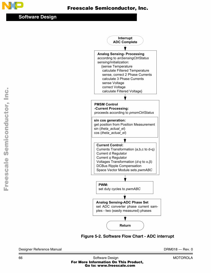
Software Design
Designer Reference Manual DRM018 — Rev. 0
66 Software Design MOTOROLA
Figure 5-2. Software Flow Chart - ADC interrupt
InterruptADC Complete
Return
Analog Sensing- Processingaccording to anSensingCtrlStatussensing/initialization:
{sense Temperaturecalculate Filtered Temperaturesense, correct 2 Phase Currentscalculate 3 Phase Currentssense Voltagecorrect Voltagecalculate Filtered Voltage}
sin cos generation:get position from Position Measurementsin (theta_actual_el)cos (theta_actual_el)
Current Control:Currents Transformation (a,b,c to d-q)Current d RegulatorCurrent q RegulatorVoltages Transformation (d-q to α,β)DCBus Ripple CompensationSpace Vector Module sets pwmABC
PMSM Control-Current Processing:proceeds according to pmsmCtrlStatus
Analog Sensing-ADC Phase Setset ADC converter phase current sam-ples - two (easily measured) phases
PWM:set duty cycles to pwmABC
Fre
esc
ale
Se
mic
on
du
cto
r, I
Freescale Semiconductor, Inc.
For More Information On This Product, Go to: www.freescale.com
nc
...
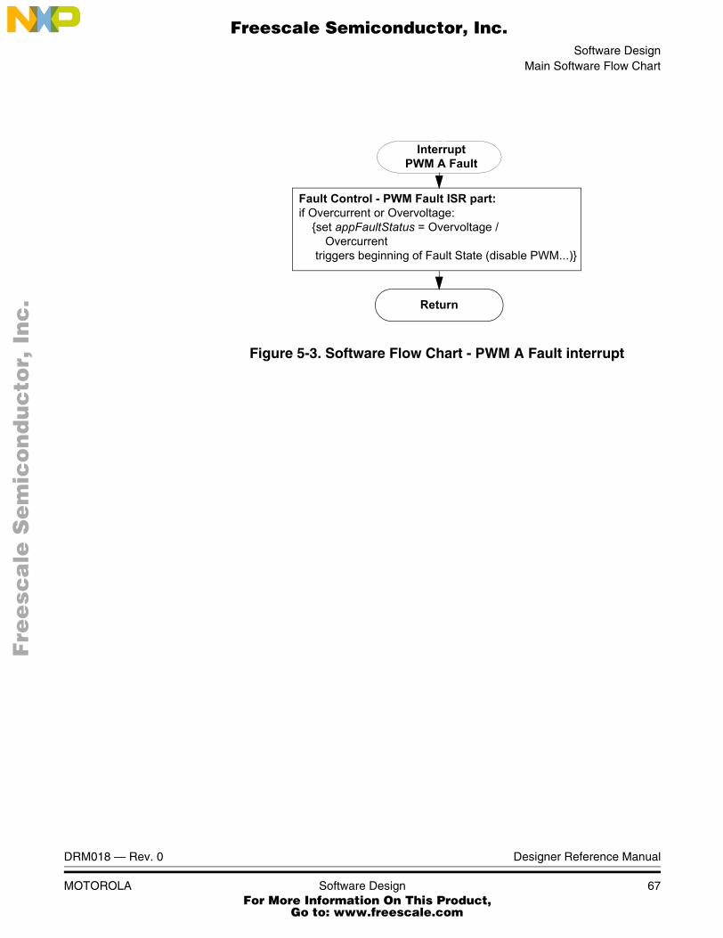
Software DesignMain Software Flow Chart
DRM018 — Rev. 0 Designer Reference Manual
MOTOROLA Software Design 67
Figure 5-3. Software Flow Chart - PWM A Fault interrupt
Return
Fault Control - PWM Fault ISR part:if Overcurrent or Overvoltage:
{set appFaultStatus = Overvoltage / Overcurrent
triggers beginning of Fault State (disable PWM...)}
Interrupt PWM A Fault
Fre
esc
ale
Se
mic
on
du
cto
r, I
Freescale Semiconductor, Inc.
For More Information On This Product, Go to: www.freescale.com
nc
...

Software Design
Designer Reference Manual DRM018 — Rev. 0
68 Software Design MOTOROLA
Figure 5-4. S/W Flow Chart - General Overview
5.3 Data Flow
The PM synchronous motor vector control drive control algorithm is described in the data flow charts shown in Figure 5-5 and Figure 5-6.
Return
Alignment:Software Timerif Timeout
{PMSM Control - End Alignment}
Speed Measurement Processing
pmsmCtrlStatus?
AlignFlag
RunFlagothers
PMSM ControlTorque, and Alignment Processing:proceeds according to its status
get speed from Speed Measurement
LED Indication Processing
Interrupt D0 QTimer
Fre
esc
ale
Se
mic
on
du
cto
r, I
Freescale Semiconductor, Inc.
For More Information On This Product, Go to: www.freescale.com
nc
...

Software DesignData Flow
DRM018 — Rev. 0 Designer Reference Manual
MOTOROLA Software Design 69
The variables and constants described should be clear from their names.
Figure 5-5. Data Flow - Part 1
PHASEA,PHASEB,INDEX
theta_actual_el
Position, SpeedMeasurement
PMSMControl
omega_actual_mechsvmSector
Pwm_AT Pwm_AB Pwm_BT Pwm_BB Pwm_CT Pwm_CB
PWM Generation
PWM Outputs
pwmABC
appState
pmsmCtrlStatus
Start/StopSwitch
PCMaster
Up/DownButtons
ApplicationControl
appFaultStatus
reloadSWtmrAlignment
Analog Sensing(Temperature, DCBus volt.
i_Sa, i_Sb, i_Scu_dc_bus
Phase Currents a,b,c)
temperature
i_Sabc_comp
temperature_filt
u_dc_bus
u_dc_bus_filt
anSensingCtrlStatus
Green LED
faultCtrlStatus
theta_align_el_C i_Sd_Alignment
reloadSWtmrSpeedControl
LEDIndication
I_SDQ_MAX
SVM_INV_INDEX,u_Reserve_FW
SVM_INV_INDEX,u_OverMax
coefBEMF, coefBEMFShift
PCMaster
Software
appPcmCtrlStatusi_Q_desired
i_Q_desired
Fre
esc
ale
Se
mic
on
du
cto
r, I
Freescale Semiconductor, Inc.
For More Information On This Product, Go to: www.freescale.com
nc
...

Software Design
Designer Reference Manual DRM018 — Rev. 0
70 Software Design MOTOROLA
Figure 5-6. Data Flow - Part 2
The data flows consist of the processes described in the following sections.
5.3.1 Application Control Process
The Application Control process is the highest software level, which precedes settings for other software levels.
The process state is determined by the variable appState.
The application can be controlled either:
• Manually
• From PC master software
PWMEN bit
PWM Faults(Overvoltage/Overcurrent)
Fault Control
temperature_filt
u_dc_bus_filt
Pwm_AT Pwm_AB Pwm_BT Pwm_BB Pwm_CT Pwm_CB
PWM GenerationPWM Outputs
i_Sabc_comp
appFaultStatus
u_dc_bus_min_fault_C
TEMPERATURE_MAX_F16
faultCtrlStatus
pmsmCtrlStatus
PCMaster
Check IndexPosition
Software
Fre
esc
ale
Se
mic
on
du
cto
r, I
Freescale Semiconductor, Inc.
For More Information On This Product, Go to: www.freescale.com
nc
...

Software DesignData Flow
DRM018 — Rev. 0 Designer Reference Manual
MOTOROLA Software Design 71
For manual control, the input of this process is the Run/Stop switch and Up/Down buttons.
The PC master software communicates via omega_reqPCM_mech,
which is the required angular speed from PC master software; appPcmCtrlStatus, which consists of the flags StartStopCtrl for Start/Stop; RequestCtrl for changing the application’s operating mode appOpMode to manual or PC control; and appFaultStatus, indicating faults.
The other processes are controlled by setting pmsmCtrlStatus, omega_required_mech, appPcmCtrlStatus, brakeCtrlStatus, faultCtrlStatus.
5.3.2 LED Indication Process
This process controls the LED flashing according to appState.
5.3.3 Analog Sensing Process
The Analog sensing process handles sensing, filtering and correction of analog variables (phase currents, temperature, DC Bus voltage).
5.3.4 Position and Speed Measurement Process
The Position and Speed Measurement process gives mechanical angular speed omega_actual_mech and electrical position theta_actual_el.
5.3.5 PMSM (PM Synchronous Motor) Control Process
The PMSM (PM Synchronous Motor) Control process provides most of the motor control functionality.
Figure 5-7 shows the data flow inside the process PMSM Current control. It shows essential subprocesses of the process: Sine; Cosine Transformations; Current Control; Speed; and Alignment Control.
Fre
esc
ale
Se
mic
on
du
cto
r, I
Freescale Semiconductor, Inc.
For More Information On This Product, Go to: www.freescale.com
nc
...
Software Design
Designer Reference Manual DRM018 — Rev. 0
72 Software Design MOTOROLA
The Sine and Cosine Transformations generate sinCos_theta_el with the components sine, cosine according to electrical position theta_actual_el. It is provided in a look-up table.
The data flow inside the process Current Control is detailed in Figure 5-7. The measured phase currents i_Sabc_comp are transformed into i_SDQ_lin using sinCos_theta_el; see 2.4.3 Vector Control Transformations. Both d and q components are regulated by independent PI regulators to i_SDQ_desired values. The outputs of the regulators are u_SDQ_lin.
Fre
esc
ale
Se
mic
on
du
cto
r, I
Freescale Semiconductor, Inc.
For More Information On This Product, Go to: www.freescale.com
nc
...

Software DesignData Flow
DRM018 — Rev. 0 Designer Reference Manual
MOTOROLA Software Design 73
Figure 5-7. Data Flow - PMSM Control - Current Control
Current qRegulator
Current Transformationa,b,c -> d-q
i_SDQ.d_axis
i_Sabc_comp
Current dRegulator
i_SDQ.q_axis
u_SDQ_lin.d_axisu_SDQ_lin.q_axis
Feed Forward
Voltage Transformationd-q -> alpha, beta
u_SAlphaBeta
u_dc_bus_filt
ScalingDCBus Ripple
Space VectorModulation
u_Salpha_RipElim
i_SDQ_desired.q_axis i_SDQ_desired.d_axis
sinCos_theta_el
svmSector
omega_actual_mech
pmsmCtrlStatus
SVM_INV_INDEX/2*
I_SDQ_MAX_F16
pwmABC
Compensation
u_LimitF16
u_SDQ
SVM_INV_INDEX,
*u_dc_bus_filt ++u_OverMax
u_OverMax
u_LimitF16sinCos_theta_el
coefBEMF, coefBEMFShift
Fre
esc
ale
Se
mic
on
du
cto
r, I
Freescale Semiconductor, Inc.
For More Information On This Product, Go to: www.freescale.com
nc
...

Software Design
Designer Reference Manual DRM018 — Rev. 0
74 Software Design MOTOROLA
The Feed Forward process provides the following calculations:
(EQ 5-1.)
(EQ 5-2.)
The u_SDQ voltages are transformed into u_SAlphaBeta (see 2.4.3 Vector Control Transformations) by the Voltage Transformation process. The Scaling DCBus Ripple Compensation block scales u_SAlphaBeta (according u_dc_bus_filt) to u_Salpha_RipElim, described in the svmlimDcBusRip function in the Motor Control Library. The space vector modulation process generates duty cycle pwmABC and svmSector according to u_Salpha_RipElim.
The u_LimitF16 is a voltage limit for current controllers. The u_OverMax constant is used to increase the limitation of u_SDQ voltages over maximum SVM_INV_INDEX/2*u_dc_bus_filt determined by the DCBus voltage and space vector modulation. Although the pwmABC will be limited by the space vector modulation process functions, the reserve might be used for field-weakening controller dynamics. In the stable state, the u_SDQ voltages vector will not exceed u_S_max_FWLimit.
The process controls the i_SDQ_desired.q_axis current according to the PMSM Control Process Status. For Alignment status, it sets i_SDQ_desired.d_axis to i_Sd_Alignment and i_SDQ_desired.q_axis to 0.
5.3.6 PWM Generation Process
The PWM generation process controls the generation of PWM signals, driving the 3-phase inverter.
The input is pwmABC, with three PWM components scaled to the range <0,1> of type Frac16. The scaling (according to PWM module setting) and the PWM module control (on the DSP) is provided by the PWM driver.
u_SDQ.q_axis coefBEMF 2coefBEMFShft omega_actual_mech⋅ ⋅ u_SDQ_lin.q_axis+=
u_SDQ.d_axis u_SDQ_lin.d_axis=
Fre
esc
ale
Se
mic
on
du
cto
r, I
Freescale Semiconductor, Inc.
For More Information On This Product, Go to: www.freescale.com
nc
...

Software DesignState Diagram
DRM018 — Rev. 0 Designer Reference Manual
MOTOROLA Software Design 75
5.3.7 Fault Control Process
The Fault Control process checks the Overheating, Undervoltage, Overvoltage, Overcurrent and Position Sensing faults.
Overheating and Undervoltage are checked by the comparisons temperature_filt < TEMPERATURE_MAX_F16 and u_dc_bus_filt < u_dc_bus_min_fault_C, where u_dc_bus_min_fault_C is initialized with U_DCB_MIN_FAULT_MAINS230_F16 or U_DCB_MIN_FAULT_MAINS115_F16. The Position Sensing fault is checked with the Check Index Position process.
The Overvoltage and Overcurrent faults are set in the PWMA Fault interrupt.
5.4 State Diagram
The software can be split into the processes shown in 5.3 Data Flow.
The following processes are described below:
• Application Control Sate Diagram
• PMSM Control State Diagram
• Fault Control State Diagram
• Analog Sensing State Diagram
All processes start with the DSP Initialization state after Reset.
5.4.1 DSP Initialization
The DSP Initialization state:
• Initializes:
– PWM
– Application Control
– PM Synchronous Motor Control
– Analog Sensing
Fre
esc
ale
Se
mic
on
du
cto
r, I
Freescale Semiconductor, Inc.
For More Information On This Product, Go to: www.freescale.com
nc
...

Software Design
Designer Reference Manual DRM018 — Rev. 0
76 Software Design MOTOROLA
– Fault Control
– LED Indication
• Sets manual application operating mode
• Enables masked interrupts
• Application Control: Initialization Triggers, which set all affected processes to the Begin Application Initialization state
5.4.2 Application Control State Diagram
The Application Control process is detailed in Figure 5-8.
Figure 5-8. State Diagram - Application Control
Application Control:StopApplication Control:
Fault BeginApplication Control:
Begin Run
Fault Control: switchState = Run
switchState = Stop
Application Control:Run
Application Control:Begin Stop
donedone
clear pmsmCtrlStatus.RunFlag
DSPInitialization
Reset
Application Control:Fault
done
Fault Control: faults cleared
switchState = Stop &
switchState = Stop &
Fault Control: Begin Fault
done
appState = APP_STOP
set appState = APP_RUN
Begin Fault
appPcmCtrlStatus.RequestCtrl = 1
set appState = APP_STOP
appState = APP_RUN
initializations finished
clear pmsmCtrlStatus.AlignFlagset appState = APP_FAULT
Application Control:Init
Initializations proceedingappState = APP_INIT
Fre
esc
ale
Se
mic
on
du
cto
r, I
Freescale Semiconductor, Inc.
For More Information On This Product, Go to: www.freescale.com
nc
...

Software DesignState Diagram
DRM018 — Rev. 0 Designer Reference Manual
MOTOROLA Software Design 77
After reset, the DSP Initialization state is entered. The peripherals and variables are initialized in this state, and the application is set to Manual Control.
When the state is finished, the Application Control Init state follows. As shown in Figure 5-8, appState = APP_INIT; all subprocesses requiring initialization are proceeding; the PWM is disabled; and so no voltage is applied on motor phases. If the appPcmCtrlStatus.RequestCtrl flag is set from PC master software. If the switchState = Stop, the Application Control enters the Stop state.
The switchState is set according to the manual switch on the EVM or PC master software register AppPcmCtrlStatus.StartStopCtrl, depending on the application operating mode.
In the Stop state, appState = APP_STOP and the PWM is disabled, so no voltage is applied on motor phases. When switchState = Run, the Begin Run state is processed. If there is a request to change application operating mode, appPcmCtrlStatus.RequestCtrl = 1, the application Init is entered and the application operating mode request can only be accepted in the Init or Stop state by transition to the Init state.
In the Begin Run state, all the processes provide settings to the Run state.
In the Run state, the PWM is enabled, so voltage is applied on motor phases. The motor is running according to the state of all subprocesses. If switchState = Stop, the Stop state is entered.
If fault is detected during the Begin Fault state, which is a subprocess of Fault control, the Begin Fault state is entered. It sets appState = APP_FAULT; the PWM is disabled; and the subprocess PMSM Control is set to Stop. The Fault state can only move onto the Init state when switchState = Stop, and the Fault Control subprocess has successfully cleared all faults.
5.4.3 PMSM Control State Diagram
A state diagram of the Commutation Control process is illustrated in Figure 5-9.
Fre
esc
ale
Se
mic
on
du
cto
r, I
Freescale Semiconductor, Inc.
For More Information On This Product, Go to: www.freescale.com
nc
...

Software Design
Designer Reference Manual DRM018 — Rev. 0
78 Software Design MOTOROLA
Figure 5-9. State Diagram - PMSM Control
When Application Control initializes, the PMSM Control subprocess initialization state is entered. The AlignInitDoneFlag is cleared, which means that alignment can proceed. The next PMSM Control state is Begin Stop or Fault. RunFlag and AlignFlag are cleared and the Stop or Fault state is entered. When Application Control: Begin Run, the PMSM Control subprocess enters the Begin Alignment or Begin Run state, depending on whether or not the alignment initialization has already proceeded (flagged by AlignInitDoneFlag). The alignment state is necessary for setting the zero position of position sensing; see 3.4.1.4 Position Reset with Rotor Alignment. In the state Begin Alignment, the Alignment current and duration are set; the alignment is provided by setting desired current for d_axis to i_Sd_Alignment and q_axis to 0. The
PMSM Control:Stop or Fault
PMSM Control:
PMSM Control:Initialization
Application Control: Begin Running
Alignment Timeout
PMSM Control:Begin Alignment
set Alignment current
Application Control: Begin Stop/Fault
done
done
Application Control: Init
PMSM Control:Run
PMSM Control:Begin Run
done
PMSM Control:Begin Stop or Fault
pmsmCtrlStatus.AlignInitDoneFlag = No
clear AlignInitDoneFlag
Begin RunningAlignInitDoneFlag = 1
set RunFlag PMSM Control:End Alignment
done Set Zero Position
set Alignment timeout
clear RunFlagclear AlignFlag
timeout searchCurrent ramp
set AlignInitDoneFlagclear AlignFlag
set AlignFlag
done
Alignment
Fre
esc
ale
Se
mic
on
du
cto
r, I
Freescale Semiconductor, Inc.
For More Information On This Product, Go to: www.freescale.com
nc
...

Software DesignState Diagram
DRM018 — Rev. 0 Designer Reference Manual
MOTOROLA Software Design 79
alignment state provides current control and timeout search. When alignment timeout occurs, End Alignment is entered. In that state, the Position Sensing Zero Position is set, so the position sensor is aligned with the real vector of the rotor flux. When the End Alignment state ends, the PMSM Control enters a regular Run state, where the motor is running at the required speed. If the Application Control state is set to Begin Stop or Begin Fault, the PMSM Control enters the Begin Stop or Fault, then the Stop or Fault.
5.4.4 Fault Control State Diagram
The state diagram of the Fault Control subprocess is illustrated in Figure 5-10. After the initialization, the fault conditions are searched. If any fault occurs, the appFaultStatus variable is set according to detected error; PWM is switched on (PWMEN bit = 0); the Fault state is entered. This state also causes Application Control: Fault state. If the faults are successfully cleared, this is signaled to the Application Control process. The Fault state is left when the Application Control Init state is entered.
Fre
esc
ale
Se
mic
on
du
cto
r, I
Freescale Semiconductor, Inc.
For More Information On This Product, Go to: www.freescale.com
nc
...

Software Design
Designer Reference Manual DRM018 — Rev. 0
80 Software Design MOTOROLA
Figure 5-10. State Diagram Fault Control
5.4.5 Analog Sensing State Diagram
The state diagram of the Analog Sensing subprocess is shown in Figure 5-11. The DSP Initialization state initializes hardware modules like ADC, synchronization with PWM, etc. In Begin Init, Initialization is started, so the variables for initialization sum and the InitDoneFlag are cleared. In the Init Proceed state, the temperature, DCBus voltage and phase current samples are sensed and summed. After required analog sensing, Init samples are sensed, and the Init Finished state is entered.
Fault Control:Application Initialization
Application Control: Init
clear appFaultStatus
Fault Control:No Fault
searching faults
Fault Control:Begin Fault
Application Control Begin Faultsetting of appFaultStatus
Fault Control:Fault
clear/test faults
Fault:Undervoltage (filtered)Overheating (filtered)Overcurrent (fault pin)Overvoltage (fault pin)
done
Fault Control:DSP Initialization
wrong PCB
pcb identification
Reset
done
PWMEN bit = 0
Position Sensing fault
Fre
esc
ale
Se
mic
on
du
cto
r, I
Freescale Semiconductor, Inc.
For More Information On This Product, Go to: www.freescale.com
nc
...

Software DesignScaling of Quantities
DRM018 — Rev. 0 Designer Reference Manual
MOTOROLA Software Design 81
There, the samples’ average is calculated, from the sum divided by the number of analog sensing Init samples. According to the phase currents’ average value, the phase current offsets are initialized.
All variable sensing is initialized and the state Init Done is entered, so the variables from analog sensing are valid for other processes. In this state, temperature and DCBus voltage are filtered in first order filters.
Figure 5-11. State Diagram - Analog Sensing
5.5 Scaling of Quantities
The PM synchronous motor vector control application uses a fractional representation for all real quantities except time.
The N-bit signed fractional format is represented using 1.[N-1] format (1 sign bit, N-1 fractional bits). Signed fractional numbers (SF) lie in the following range:
(EQ 5-3.)
Analog Sensing:Begin Init
Analog SensingInit Done,
Analog SensingInit. Proceed:
Analog SensingDSP Initialization
Reset
clear variables
Application Control: Begin Initsamples counter =
Application Control: Begin Init
clear InitDoneFlag
Analog SensingInit Finished:
samples average
done
done
set current offsets
sense and sum samples
count samples
analog sensing init samples
set InitDoneFlag
normal operation:
1.0� SF +1.0 -2 N 1�[ ]�≤ ≤
Fre
esc
ale
Se
mic
on
du
cto
r, I
Freescale Semiconductor, Inc.
For More Information On This Product, Go to: www.freescale.com
nc
...
Software Design
Designer Reference Manual DRM018 — Rev. 0
82 Software Design MOTOROLA
For words and long-word signed fractions, the most negative number that can be represented is -1.0, whose internal representation is $8000 and $80000000, respectively. The most positive word is $7FFF or 1.0 - 2-15, and the most positive long-word is $7FFFFFFF or 1.0 - 2-31.
The following equation shows the relationship between the real and fractional representations:
(EQ 5-4.)
where:
Fractional Value is the fractional representation of the real value [Frac16]
Real Values is the real value of the quantity [V, A, RPM, etc.]
Real Quantity Range Max is the maximum of the quantity range, defined inthe application [V, A, RPM, etc.]
The C language standard does not have any fractional variable type defined. Therefore, fractional operations are provided by CodeWarrior intrinsics functions (e.g. mult_r() ). As a substitution for the fractional type variables, the application uses types Frac16 and Frac32. These are in fact defined as integer 16-bit signed variables and integer 32-bit signed variables. The difference between Frac16 and pure integer variables is that Frac16 and Frac32 declared variables should only be used with fractional operations (intrinsics functions).
A recalculation from real to a fractional form and Frac16, Frac32 value is made with the following equations:
(EQ 5-5.)
for Frac16 16-bit signed value and:
(EQ 5-6.)
Fractional Value Real ValueReal Quantity Range Max--------------------------------------------------------------=
Frac16 Value 32768 Real ValueReal Quantity Range Max--------------------------------------------------------------⋅=
Frac32 Value 231 Real ValueReal Quantity Range Max--------------------------------------------------------------⋅=
Fre
esc
ale
Se
mic
on
du
cto
r, I
Freescale Semiconductor, Inc.
For More Information On This Product, Go to: www.freescale.com
nc
...
Software DesignScaling of Quantities
DRM018 — Rev. 0 Designer Reference Manual
MOTOROLA Software Design 83
for Frac32 32-bit signed value.
(EQ 5-7.)
Fractional form, a conversion from Fraction Value to Frac16 and Frac32 Value can be provided by the C language macro.
5.5.1 Voltage Scaling
Voltage scaling results from the sensing circuits of the hardware used; for details see the 3-Phase AC/BLDC Low-Voltage Power Stage User’s Manual.
Voltage quantities are scaled to the maximum measurable voltage, which is dependent on the hardware. The relationship between real and fractional representations of voltage quantities is:
(EQ 5-8.)
where:
uFrac Fractional representation of voltage [-]
uReal Real voltage quantities in physical units [V]
VOLT_RANGE_MAXDefined voltage range maximum used for scaling inphysical units [V]
In the application, the VOLT_RANGE_MAX value is the maximum measurable DCBus voltage:
VOLT_RANGE_MAX = 407 V
All application voltage variables are scaled in the same way (u_dc_bus, u_dc_bus_filt, u_SAlphaBeta, u_SDQ, u_SAlphaBeta, and so on).
Fractional Value Real ValueReal Quantity Range Max--------------------------------------------------------------=
uFracuReal
VOLT_RANGE_MAX--------------------------------------------------------=
Fre
esc
ale
Se
mic
on
du
cto
r, I
Freescale Semiconductor, Inc.
For More Information On This Product, Go to: www.freescale.com
nc
...

Software Design
Designer Reference Manual DRM018 — Rev. 0
84 Software Design MOTOROLA
5.5.2 Current Scaling
Current scaling also results from the sensing circuits of the hardware used; for details see 3-Phase AC/BLDC Low-Voltage Power Stage User’s Manual.
The relationship between real and fractional representation of current quantities is:
(EQ 5-9.)
where:
iFrac Fractional representation of current quantities [-]
iReal Real current quantities in physical units [A]
CURR_RANGE_MAXDefined current range maximum used for scaling inphysical units[A]
In the application, the CURR_RANGE_MAX value is the maximum measurable current:
CURR_RANGE_MAX = 5.86 A
All application current variables are scaled in the same way (components of i_Sabc_comp, i_SAlphaBeta, i_SDQ, i_SDQ_desired, i_Sd_Alignment and so forth).
NOTE: As shown in 3-Phase AC/BLDC Low-Voltage Power Stage User’s Manual, the current sensing circuit provides measurement of the current in the range from CURR_MIN = -2.93A to CURR_MAX = +2.93A, giving the voltage for the ADC input ranges from 0 to 3.3V with 1.65V offset. The DSP5680x’s ADC converter is able to automatically cancel (subtract) the offset. The fractional representation of the measured current is then in the range <-0.5, 0.5), while the possible representation of a fractional value is <-1,1), as shown in (EQ 5-5.). Therefore, CURR_RANGE_MAX is calculated according to the following equation:
(EQ 5-10.)
iFraciReal
CURR_RANGE_MAX---------------------------------------------------------=
CURR_RANGE_MAX CURR_MAX-CURR_MIN 2 CURR_MAX⋅= =
Fre
esc
ale
Se
mic
on
du
cto
r, I
Freescale Semiconductor, Inc.
For More Information On This Product, Go to: www.freescale.com
nc
...

Software DesignScaling of Quantities
DRM018 — Rev. 0 Designer Reference Manual
MOTOROLA Software Design 85
5.5.3 Speed Scaling
Speed quantities are scaled to the defined speed range maximum, which should be set lower than all speed variables in the application, so it was set higher than the maximum mechanical speed of the drive. The relationship between real and fractional representation of speed quantities is:
(EQ 5-11.)
where:
ωFrac Fractional representation of speed quantities [-]
ωReal Real speed quantities in physical units [rpm]
OMEGA_RANGE_MAXDefined speed range maximum used for scaling inphysical units[rpm]
In the application, the OMEGA_RANGE_MAX value is defined as:
OMEGA_RANGE_MAX = 6000rpm
The relation between speed scaling and speed measurement with encoder is described in 3.4.1.2 Speed Sensing. In the final software, the constant OMEGA_SCALE is identical with the scaling constant k in equations (EQ 3-3.) and (EQ 3-4.), and OMEGA_RANGE_MAX is ωMax.
5.5.4 Position Scaling
Position Scaling is described in 3.4.1.1 Position Sensing
5.5.5 Temperature Scaling
As shown in 3.4.4 Power Module Temperature Sensing, the temperature variable does not have a linear dependency.
ωFracωReal
OMEGA_RANGE_MAX--------------------------------------------------------------=
Fre
esc
ale
Se
mic
on
du
cto
r, I
Freescale Semiconductor, Inc.
For More Information On This Product, Go to: www.freescale.com
nc
...

Software Design
Designer Reference Manual DRM018 — Rev. 0
86 Software Design MOTOROLA
5.6 PI Controller Tuning
The application consists of four PI controllers. Two controllers are used for the Id and Iq currents. The controller’s constants are given by simulation in Mathlab and were experimentally specified. A detailed description of controller tuning is beyond the scope of this reference design.
5.7 Subprocesses Relation and State Transitions
As shown in 5.3 Data Flow and 5.4 State Diagram, the software is split into subprocesses according to functionality. The application code is designed to be able to extract individual processes, such as Analog Sensing, and use them for customer applications. The C language functions dedicated for each process are located in one place in the software, so they can be easily used for other applications. The function naming usually starts with the name of the process, for example, AnalogSensingInitProceed().
As 5.4 State Diagram shows, the processes’ or subprocesses’, state transients have some mutual relations. For example, Application Control: Begin Initialization is a condition for transient of the Analog Sensing process: Init Done to Begin Init state. In the code, the interface between processes is provided via “trigger” functions. The naming convention is for these functions is: <ProcessName><State>Trig().
The functionality will be explained in following example:
The “trigger” function Process1StateTrig() is called from process1. The transient functions of process2, process3,etc., which must be triggered by Process1State, are put inside the Process1StateTrig().
Fre
esc
ale
Se
mic
on
du
cto
r, I
Freescale Semiconductor, Inc.
For More Information On This Product, Go to: www.freescale.com
nc
...

DRM018 — Rev. 0 Designer Reference Manual
MOTOROLA System Setup 87
Designer Reference Manual — 3-Ph. PMSM Torque Vector Control
Section 6. System Setup
6.1 Contents
6.2 Application Description . . . . . . . . . . . . . . . . . . . . . . . . . . . . . . .87
6.3 Application Set-Up . . . . . . . . . . . . . . . . . . . . . . . . . . . . . . . . . .93
6.4 Projects Files . . . . . . . . . . . . . . . . . . . . . . . . . . . . . . . . . . . . . .97
6.5 Application Build & Execute . . . . . . . . . . . . . . . . . . . . . . . . . . .98
6.6 Warning . . . . . . . . . . . . . . . . . . . . . . . . . . . . . . . . . . . . . . . . .100
6.2 Application Description
The vector control algorithm is calculated on the Motorola DSP56F805. The algorithm generates the 3-phase PWM signals for Permanent Magnet (PM) synchronous motor inverter according to the user-required inputs, measured and calculated signals.
The concept of the PMSM drive incorporates the following hardware components:
• BLDC motor-brake set
• 3-phase AC/BLDC high voltage power stage
• DSP56F805EVM boards
• ECOPTINL - In-line optoisolation box, which is connected between the host computer and the DSP56F805EVM
The BLDC motor--brake set incorporates a 3-phase BLDC motor and attached BLDC motor brake. The BLDC motor has six poles. The incremental position sensor (encoder) is coupled on the motor shaft and position Hall Sensors are mounted between the motor and the brake.
Fre
esc
ale
Se
mic
on
du
cto
r, I
Freescale Semiconductor, Inc.
For More Information On This Product, Go to: www.freescale.com
nc
...

System Setup
Designer Reference Manual DRM018 — Rev. 0
88 System Setup MOTOROLA
They allow to position sensing if required by the control algorithm. The detailed motor--brake specifications are listed in Table 6-1.
NOTE: The application software is targeted for PM Synchronous motor with sine-wave Back-EMF shape. In this particular demo application, the BLDC motor is used instead, due to the availability of the BLDC motor--Brake SM40V+SG40N, supplied as ECMTRHIVBLDC. Although the Back-EMF shape of this motor is not ideally sine-wave, it can be controlled by the application software. The drive parameters will be improved when a PMSM motor with an exact sine-wave Back-EMF shape is used.
The drive can be controlled in two different operating modes:
• Manual operating mode - the required speed is set by UP/DOWN push buttons and the drive is started and stopped by the RUN/STOP switch on the EVM board.
Table 6-1. Motor--Brake Specifications
Motor Characteristics
Motor Type6 poles, 3-phase, star
connected, BLDC motor
Speed Range 2500 rpm (at 310V)
Max. Electrical Power 150 W
Phase Voltage 3*220V
Phase Current 0.55A
Drive Characteristics
Speed Range < 2500 rpm
Input Voltage 310V DC
Max DC Bus Voltage 380 V
Control Algorithm Current Closed Loop Control
Optoisolation Required
Motor Characteristics
Motor Type6 poles,3-phase, star
connected, BLDC motor
Speed Range 2500 rpm (at 310V)
Max. Electrical Power 150 W
Fre
esc
ale
Se
mic
on
du
cto
r, I
Freescale Semiconductor, Inc.
For More Information On This Product, Go to: www.freescale.com
nc
...

System SetupApplication Description
DRM018 — Rev. 0 Designer Reference Manual
MOTOROLA System Setup 89
• PC master software operating mode - the required torque producing current is set by the PC master software.
Measured quantities:
• DC Bus voltage
• Phase currents (phase A, phase B, phase C)
• Power module temperature
• Rotor speed
The faults used for drive protection:
• Overvoltage (PC master software error message = Overvoltage fault)
• Undervoltage (PC master software error message = Undervoltage fault)
• Overcurrent (PC master software error message = Overcurrent fault)
• Overheating (PC master software error message = Overheating fault)
6.2.1 Drive Protection
The DC Bus voltage, DC Bus current and power stage temperature are measured during the control process. They protect the drive from over voltage, undervoltage, overcurrent and overheating. The undervoltage and overheating protection is performed by software, while the overcurrent and over voltage fault signal utilizes a fault input of the DSP. The power stage is identified using board identification. If the correct power stage is not identified, the fault “Wrong Power Stage” disables the drive operation. Line voltage is measured during application initialization and the application automatically adjusts itself to run at either 115V AC or 230V AC, depending on the measured value.
If any of the above-mentioned faults occur, the motor control PWM outputs are disabled to protect the drive, and the application enters the FAULT state. The FAULT state can be left only when the fault conditions
Fre
esc
ale
Se
mic
on
du
cto
r, I
Freescale Semiconductor, Inc.
For More Information On This Product, Go to: www.freescale.com
nc
...

System Setup
Designer Reference Manual DRM018 — Rev. 0
90 System Setup MOTOROLA
disappear and the RUN/STOP switch is moved to the STOP position manual mode and by the PC master software in the PC master software remote mode.
The application can run on:
• External RAM or Flash
• 3-Phase AC/BLDC Low-Voltage Power Stage powered by 12 DC
• Manual or PC master software Operating Mode
The correct power stage and voltage level is identified automatically and the appropriate constants are set.
The 3-phase PM synchronous motor control application can operate in two modes:
1. Manual Operating ModeThe drive is controlled by the RUN/STOP switch (S6). The motor torque producing current is set by the UP (S2-IRQB) and DOWN (S1-IRQA) push buttons; see Figure 6-1. If the application runs and motor spinning is disabled (i.e., the system is ready) the USER LED (LED3, shown in Figure 6-2) will blink. When motor spinning is enabled, the USER LED is On. Refer to Table 6-2 for application states.
Fre
esc
ale
Se
mic
on
du
cto
r, I
Freescale Semiconductor, Inc.
For More Information On This Product, Go to: www.freescale.com
nc
...

System SetupApplication Description
DRM018 — Rev. 0 Designer Reference Manual
MOTOROLA System Setup 91
Figure 6-1. RUN/STOP Switch and UP/DOWN Buttonsat DSP56F805EVM
Figure 6-2. USER and PWM LEDs at DSP56F805EVM
Fre
esc
ale
Se
mic
on
du
cto
r, I
Freescale Semiconductor, Inc.
For More Information On This Product, Go to: www.freescale.com
nc
...
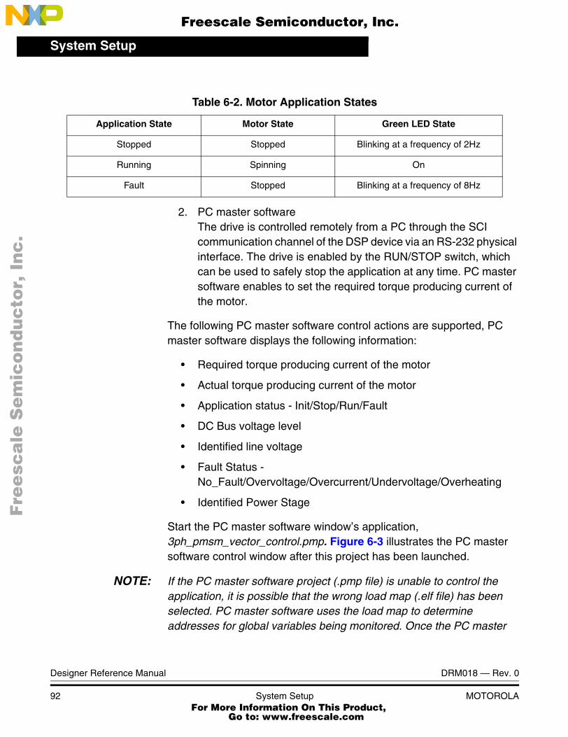
System Setup
Designer Reference Manual DRM018 — Rev. 0
92 System Setup MOTOROLA
2. PC master softwareThe drive is controlled remotely from a PC through the SCI communication channel of the DSP device via an RS-232 physical interface. The drive is enabled by the RUN/STOP switch, which can be used to safely stop the application at any time. PC master software enables to set the required torque producing current of the motor.
The following PC master software control actions are supported, PC master software displays the following information:
• Required torque producing current of the motor
• Actual torque producing current of the motor
• Application status - Init/Stop/Run/Fault
• DC Bus voltage level
• Identified line voltage
• Fault Status - No_Fault/Overvoltage/Overcurrent/Undervoltage/Overheating
• Identified Power Stage
Start the PC master software window’s application, 3ph_pmsm_vector_control.pmp. Figure 6-3 illustrates the PC master software control window after this project has been launched.
NOTE: If the PC master software project (.pmp file) is unable to control the application, it is possible that the wrong load map (.elf file) has been selected. PC master software uses the load map to determine addresses for global variables being monitored. Once the PC master
Table 6-2. Motor Application States
Application State Motor State Green LED State
Stopped Stopped Blinking at a frequency of 2Hz
Running Spinning On
Fault Stopped Blinking at a frequency of 8Hz
Fre
esc
ale
Se
mic
on
du
cto
r, I
Freescale Semiconductor, Inc.
For More Information On This Product, Go to: www.freescale.com
nc
...

System SetupApplication Set-Up
DRM018 — Rev. 0 Designer Reference Manual
MOTOROLA System Setup 93
software project has been launched, this option may be selected in the PC master software window under Project/Select Other Map FileReload.
Figure 6-3. PC Master Software Control Window
6.3 Application Set-Up
Figure 6-4 illustrates the hardware set-up for the 3-phase PM Synchronous Motor Control application.
Fre
esc
ale
Se
mic
on
du
cto
r, I
Freescale Semiconductor, Inc.
For More Information On This Product, Go to: www.freescale.com
nc
...
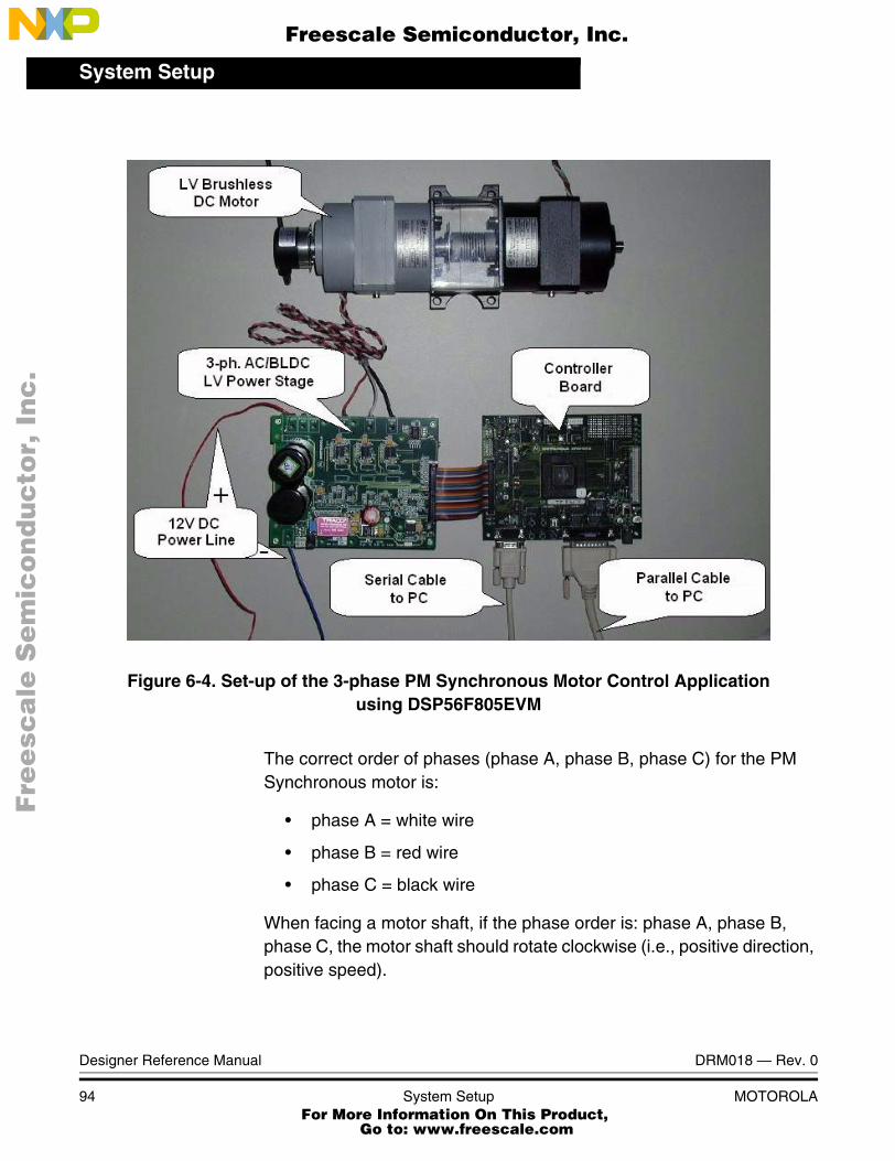
System Setup
Designer Reference Manual DRM018 — Rev. 0
94 System Setup MOTOROLA
Figure 6-4. Set-up of the 3-phase PM Synchronous Motor Control Applicationusing DSP56F805EVM
The correct order of phases (phase A, phase B, phase C) for the PM Synchronous motor is:
• phase A = white wire
• phase B = red wire
• phase C = black wire
When facing a motor shaft, if the phase order is: phase A, phase B, phase C, the motor shaft should rotate clockwise (i.e., positive direction, positive speed).
Fre
esc
ale
Se
mic
on
du
cto
r, I
Freescale Semiconductor, Inc.
For More Information On This Product, Go to: www.freescale.com
nc
...

System SetupApplication Set-Up
DRM018 — Rev. 0 Designer Reference Manual
MOTOROLA System Setup 95
For detailed information, see the DSP56F805 Evaluation Module Hardware Reference Manual. The serial cable is needed for the PC master software debugging/control.
The system consists of the following components:
• BLDC Motor Type SM 40V, EM Brno s.r.o., Czech Republic
• Load Type SG 40N, EM Brno s.r.o., Czech RepublicDSP56F805 Board:
• Encoder BHK 16.05A1024-12-5, Baumer Electric, Switzerland
• 3-ph AC BLDC LV Power Stage 180W
• Serial cable - needed for the PC master software debugging tool only.
• The parallel cable - needed for the Metrowerks Code Warrior debugging and s/w loading.
• Command Converter Cable - needed for the DSP56F805 Controller Board only.
For detailed information, refer to the dedicated application note (see References).
6.3.1 Application Setup Using DSP56F805EVM
To execute the Three-Phase PM Synchronous Motor Vector Control, the DSP56F805EVM board requires the strap settings shown in Figure 6-5 and Table 6-3.
Fre
esc
ale
Se
mic
on
du
cto
r, I
Freescale Semiconductor, Inc.
For More Information On This Product, Go to: www.freescale.com
nc
...

System Setup
Designer Reference Manual DRM018 — Rev. 0
96 System Setup MOTOROLA
Figure 6-5. DSP56F805EVM Jumper Reference
JG8
JG9
DSP56F805EVM
JG31
J29
JTAG
JG141
P3
USER
S/N
LED3
P1
Y1
U1
U15
S2 S3
3
12
JG13
S1
S4 S5 S6
P1
PWM
47
369
JG121
32
JG131
32
J23 J24
JG6
JG1 JG21
1
JG9JG7
JG5U9 U10
JG41
JG8
RESETIRQBIRQA
RUN/STOPGP2GP1
12
78
JG4
1 2
7 8
JG3
3
12
JG123 1
4
JG14JG10
69 7
JG10
1JG1
3
1JG6
3
1JG2
3
JG5
JG15
3 1
JG11
3 1
JG16
3 1
JG15
1
JG16
1
JG11
1
JG18
JG17
JG17JG18
JG7
Table 6-3. DSP56F805EVM Jumper Settings
Jumper Group Comment Connections
JG1 PD0 input selected as a high 1-2
JG2 PD1 input selected as a high 1-2
JG3 Primary UNI-3 serial selected 1-2, 3-4, 5-6, 7-8
JG4 Secondary UNI-3 serial selected 1-2, 3-4, 5-6, 7-8
JG5Enable on-board parallel JTAG Command Converter
InterfaceNC
JG6 Use on-board crystal for DSP oscillator input 2-3
JG7 Select DSP’s Mode 0 operation upon exit from reset 1-2
JG8 Enable on-board SRAM 1-2
JG9 Enable RS-232 output 1-2
Fre
esc
ale
Se
mic
on
du
cto
r, I
Freescale Semiconductor, Inc.
For More Information On This Product, Go to: www.freescale.com
nc
...
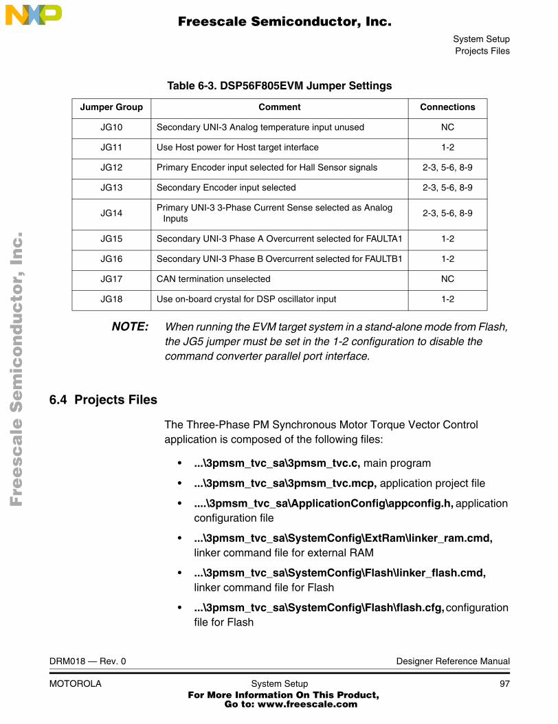
System SetupProjects Files
DRM018 — Rev. 0 Designer Reference Manual
MOTOROLA System Setup 97
NOTE: When running the EVM target system in a stand-alone mode from Flash, the JG5 jumper must be set in the 1-2 configuration to disable the command converter parallel port interface.
6.4 Projects Files
The Three-Phase PM Synchronous Motor Torque Vector Control application is composed of the following files:
• ...\3pmsm_tvc_sa\3pmsm_tvc.c, main program
• ...\3pmsm_tvc_sa\3pmsm_tvc.mcp, application project file
• ....\3pmsm_tvc_sa\ApplicationConfig\appconfig.h, application configuration file
• ...\3pmsm_tvc_sa\SystemConfig\ExtRam\linker_ram.cmd, linker command file for external RAM
• ...\3pmsm_tvc_sa\SystemConfig\Flash\linker_flash.cmd, linker command file for Flash
• ...\3pmsm_tvc_sa\SystemConfig\Flash\flash.cfg, configuration file for Flash
JG10 Secondary UNI-3 Analog temperature input unused NC
JG11 Use Host power for Host target interface 1-2
JG12 Primary Encoder input selected for Hall Sensor signals 2-3, 5-6, 8-9
JG13 Secondary Encoder input selected 2-3, 5-6, 8-9
JG14Primary UNI-3 3-Phase Current Sense selected as Analog
Inputs2-3, 5-6, 8-9
JG15 Secondary UNI-3 Phase A Overcurrent selected for FAULTA1 1-2
JG16 Secondary UNI-3 Phase B Overcurrent selected for FAULTB1 1-2
JG17 CAN termination unselected NC
JG18 Use on-board crystal for DSP oscillator input 1-2
Table 6-3. DSP56F805EVM Jumper Settings
Jumper Group Comment Connections
Fre
esc
ale
Se
mic
on
du
cto
r, I
Freescale Semiconductor, Inc.
For More Information On This Product, Go to: www.freescale.com
nc
...

System Setup
Designer Reference Manual DRM018 — Rev. 0
98 System Setup MOTOROLA
• ...\3pmsm_tvc_sa\PCMaster\3pmsm_tvc.pmp, PC master software file
These files are located in the application folder.
• ...\controller_new.c, .h: source and header files for PI controller
• ...\ramp.c, .h: source and header files for ramp generation
• ...\svm.c, .h: source and header files for space vector modulation
• ...\cptrfm.c, .h: source and header files for Clark and Park transformation
• ...\mfr16.c, .h, mfr32.c, .h, mfr32sqrt.asm, portasm.h: source, header and asm files providing fractional math intrinsics
All the necessary resources (algorithms and peripheral drivers) are part of the application project file.
• ...\3pmsm_tvc\src\include, folder for general C-header files
• ...\3pmsm_tvc\src\dsp56805, folder for the device specific source files, e.g. drivers
• ...\3ph_pmsm_vector_control_sa\src\pc_master_support, folder for PC master software source files
• ...\3pmsm_tvc\src\algorithms\, folder for algorithms
6.5 Application Build & Execute
When building the Three-Phase PM Synchronous Motor Vector Control, the user can create an application that runs from internal Flash or External RAM. To select the type of application to build, open the 3ph_pmsm_vector_control.mcp project and select the target build type, as shown in Figure 6-6. A definition of the projects associated with these target build types may be viewed under the Targets tab of the project window.
Fre
esc
ale
Se
mic
on
du
cto
r, I
Freescale Semiconductor, Inc.
For More Information On This Product, Go to: www.freescale.com
nc
...

System SetupApplication Build & Execute
DRM018 — Rev. 0 Designer Reference Manual
MOTOROLA System Setup 99
Figure 6-6. Target Build Selection
The project may now be built by executing the Make command, as shown in Figure 6-7. This will build and link the Three-Phase PM Synchronous Motor Torque Vector Control Application.
Figure 6-7. Execute Make Command
Fre
esc
ale
Se
mic
on
du
cto
r, I
Freescale Semiconductor, Inc.
For More Information On This Product, Go to: www.freescale.com
nc
...

System Setup
Designer Reference Manual DRM018 — Rev. 0
100 System Setup MOTOROLA
To execute the Three-Phase PM Synchronous Motor Vector Control application, select Project\Debug in the CodeWarrior IDE, followed by the Run command. For more help with these commands, refer to the CodeWarrior tutorial documentation in the following file located in the CodeWarrior installation folder:
<...>\CodeWarrior Documentation\PDF\Targeting_DSP56800.pdf
If the Flash target is selected, CodeWarrior will automatically program the internal Flash of the DSP with the executable generated during Build. If the External RAM target is selected, the executable will be loaded to off-chip RAM.
Once Flash has been programmed with the executable, the EVM target system may be run in a stand-alone mode from Flash. To do this, set the JG5 jumper in the 1-2 configuration to disable the parallel port, and press the RESET button.
Once the application is running, move the RUN/STOP switch to the RUN position and set the required speed using the UP/DOWN push buttons. Pressing the UP/DOWN buttons should incrementally increase the motor speed until it reaches maximum speed. If successful, the motor will be spinning.
NOTE: If the RUN/STOP switch is set to the RUN position when the application starts, toggle the RUN/STOP switch between the STOP and RUN positions to enable motor spinning. This is a protection feature that prevents the motor from starting when the application is executed from CodeWarrior.
You should also see a lighted green LED, which indicates that the application is running. If the application is stopped, the green LED will blink at a 2Hz frequency. If an Undervoltage fault occurs, the green LED will blink at a frequency of 8Hz.
6.6 Warning
This application operates in an environment that includes dangerous voltages and rotating machinery.
Fre
esc
ale
Se
mic
on
du
cto
r, I
Freescale Semiconductor, Inc.
For More Information On This Product, Go to: www.freescale.com
nc
...

System SetupWarning
DRM018 — Rev. 0 Designer Reference Manual
MOTOROLA System Setup 101
Be aware that the application power stage and optoisolation board are not electrically isolated from the mains voltage - they are live with risk of electric shock when touched.
An isolation transformer should be used when operating off an ac power line. If an isolation transformer is not used, power stage grounds and oscilloscope grounds are at different potentials, unless the oscilloscope is floating. Note that probe grounds and, therefore, the case of a floated oscilloscope are subjected to dangerous voltages.
The user should be aware that:
• Before moving scope probes, making connections, etc., it is generally advisable to power down the high-voltage supply.
• To avoid inadvertently touching live parts, use plastic covers.
• When high voltage is applied, using only one hand for operating the test setup minimizes the possibility of electrical shock.
• Operation in lab setups that have grounded tables and/or chairs should be avoided.
• Wearing safety glasses, avoiding ties and jewelry, using shields, and operation by personnel trained in high-voltage lab techniques are also advisable.
• Power transistors, the PFC coil, and the motor can reach temperatures hot enough to cause burns.
• When powering down; due to storage in the bus capacitors, dangerous voltages are present until the power-on LED is off.
Fre
esc
ale
Se
mic
on
du
cto
r, I
Freescale Semiconductor, Inc.
For More Information On This Product, Go to: www.freescale.com
nc
...

System Setup
Designer Reference Manual DRM018 — Rev. 0
102 System Setup MOTOROLA
Fre
esc
ale
Se
mic
on
du
cto
r, I
Freescale Semiconductor, Inc.
For More Information On This Product, Go to: www.freescale.com
nc
...

DRM018 — Rev. 0 Designer Reference Manual
MOTOROLA References 103
Designer Reference Manual — 3-Ph. PMSM Torque Vector Control
Appendix A. References
1. Design of Brushless Permanent-magnet Motors, J.R. Hendershot JR and T.J.E. Miller, Magna Physics Publishing and Clarendon Press, 1994
2. Sensorless Vector and Direct Torque Control, P. Vas (1998), Oxford University Press, ISBN 0-19-856465-1, New York.
3. DSP56F80x 16-bit Digital Signal Processor, User’s Manual, DSP56F801-7UM/D, Motorola, 2001
4. DSP56F800 16-bit Digital Signal Processor, Family Manual, DSP56F800FM/D, Motorola, 2001
5. 3-Phase AC/BLDC Low-Voltage Power Stage User’s Manual, MEMC3PBLDCLVUM/D , Motorola, 2000
6. User’s Manual for PC master software, Motorola, 2001
7. Evaluation Motor Board User’s Manual, MEMCEVMBUM/D, Motorola
8. Motorola Embedded Motion Optoisolation Board User’s Manual, MEMCOBUM/D, Motorola, 2000
9. DSP Parallel Command Converter Hardware User’s Manual, MCSL, MC108UM2R1
10. CodeWarrior for Motorola DSP56800 Embedded Systems, CWDSP56800, Metrowerks, 2001.
Fre
esc
ale
Se
mic
on
du
cto
r, I
Freescale Semiconductor, Inc.
For More Information On This Product, Go to: www.freescale.com
nc
...

References
Designer Reference Manual DRM018 — Rev. 0
104 References MOTOROLA
Fre
esc
ale
Se
mic
on
du
cto
r, I
Freescale Semiconductor, Inc.
For More Information On This Product, Go to: www.freescale.com
nc
...

DRM018 — Rev. 0 Designer Reference Manual
MOTOROLA Glossary 105
Designer Reference Manual — 3-Ph. PMSM Torque Vector Control
Appendix B. Glossary
AC — Alternating Current
ADC — Analogue-to-Digital Converter
brush — A component transfering elektrical power from non-rotational terminals, mounted on the stator, to the rotor.
BLDC — Brushless DC motor
commutation — A process providing the creation of a rotation field by switching of power transistor (electronic replacement of brush and commutator).
commutator — A mechanical device alternating DC current in DC commutator motor and providing rotation of DC commutator motor.
COP — Computer Operating Properly timer
DC — Direct Current
DSP — Digital Signal Prosessor
DSP56F80x — A Motorola family of 16-bit DSPs dedicated for motor control.
DT — see “Dead Time (DT)”
Dead Time (DT) — A short time that must be inserted between the turning off of one transistor in the inverter half bridge and turning on of the complementary transistor due to the limited switching speed of the transistors.
duty cycle — A ratio of the amount of time the signal is on versus the time it is off. Duty cycle is usually represented by a percentage.
GPIO — General Purpose Input/Output
Fre
esc
ale
Se
mic
on
du
cto
r, I
Freescale Semiconductor, Inc.
For More Information On This Product, Go to: www.freescale.com
nc
...
Glossary
Designer Reference Manual DRM018 — Rev. 0
106 Glossary MOTOROLA
Hall Sensors - A position sensor giving six defined events (each 60 electrical degrees) per electrical revolution (for 3-phase motor).
HV- High Voltage
interrupt — A temporary break in the sequential execution of a program to respond to signals from peripheral devices by executing a subroutine.
input/output (I/O) — Input/output interfaces between a computer system and the external world. A CPU reads an input to sense the level of an external signal and writes to an output to change the level on an external signal.
JTAG — Interface allowing On-Chip Emulation and Programming
LED — Lignt Emiting Diode
logic 1 — A voltage level approximately equal to the input power voltage (VDD).
logic 0 — A voltage level approximately equal to the ground voltage (VSS).
LV- Low Voltage
PI controller — Proportional-Integral controller
phase-locked loop (PLL) — A clock generator circuit in which a voltage controlled oscillator produces an oscillation which is synchronized to a reference signal.
PM — Permanent Magnet
PMSM - Permanent Magnet Synchronous Motor
PWM — Pulse Width Modulation
Quadrature Decoder — A module providing decoding of position from a quadrature encoder mounted on a motor shaft.
Quad Timer — A module with four 16-bit timers
reset — To force a device to a known condition.
Fre
esc
ale
Se
mic
on
du
cto
r, I
Freescale Semiconductor, Inc.
For More Information On This Product, Go to: www.freescale.com
nc
...

Glossary
DRM018 — Rev. 0 Designer Reference Manual
MOTOROLA Glossary 107
RPM — Revolutions per minute
SCI — See "serial communication interface module (SCI)"
serial communications interface module (SCI) — A module that supports asynchronous communication.
serial peripheral interface module (SPI) — A module that supports synchronous communication.
software — Instructions and data that control the operation of a microcontroller.
software interrupt (SWI) — An instruction that causes an interrupt and its associated vector fetch.
SPI — See "serial peripheral interface module (SPI)."
timer — A module used to relate events in a system to a point in time.
Fre
esc
ale
Se
mic
on
du
cto
r, I
Freescale Semiconductor, Inc.
For More Information On This Product, Go to: www.freescale.com
nc
...

Glossary
Designer Reference Manual DRM018 — Rev. 0
108 Glossary MOTOROLA
Fre
esc
ale
Se
mic
on
du
cto
r, I
Freescale Semiconductor, Inc.
For More Information On This Product, Go to: www.freescale.com
nc
...

Fre
esc
ale
Se
mic
on
du
cto
r, I
Freescale Semiconductor, Inc.
For More Information On This Product, Go to: www.freescale.com
nc
...

HOW TO REACH US:
USA/EUROPE/LOCATIONS NOT LISTED:
Motorola Literature Distribution; P.O. Box 5405, Denver, Colorado 80217 1-303-675-2140 or 1-800-441-2447
JAPAN:
Motorola Japan Ltd.; SPS, Technical Information Center, 3-20-1, Minami-Azabu Minato-ku, Tokyo 106-8573 Japan81-3-3440-3569
ASIA/PACIFIC:
Motorola Semiconductors H.K. Ltd.; Silicon Harbour Centre, 2 Dai King Street, Tai Po Industrial Estate, Tai Po, N.T., Hong Kong852-26668334
TECHNICAL INFORMATION CENTER:
1-800-521-6274
HOME PAGE:
http://motorola.com/semiconductors
Information in this document is provided solely to enable system and software
implementers to use Motorola products. There are no express or implied copyright
licenses granted hereunder to design or fabricate any integrated circuits or
integrated circuits based on the information in this document.
Motorola reserves the right to make changes without further notice to any products
herein. Motorola makes no warranty, representation or guarantee regarding the
suitability of its products for any particular purpose, nor does Motorola assume any
liability arising out of the application or use of any product or circuit, and specifically
disclaims any and all liability, including without limitation consequential or incidental
damages. “Typical” parameters which may be provided in Motorola data sheets
and/or specifications can and do vary in different applications and actual
performance may vary over time. All operating parameters, including “Typicals”
must be validated for each customer application by customer’s technical experts.
Motorola does not convey any license under its patent rights nor the rights of
others. Motorola products are not designed, intended, or authorized for use as
components in systems intended for surgical implant into the body, or other
applications intended to support or sustain life, or for any other application in which
the failure of the Motorola product could create a situation where personal injury or
death may occur. Should Buyer purchase or use Motorola products for any such
unintended or unauthorized application, Buyer shall indemnify and hold Motorola
and its officers, employees, subsidiaries, affiliates, and distributors harmless
against all claims, costs, damages, and expenses, and reasonable attorney fees
arising out of, directly or indirectly, any claim of personal injury or death associated
with such unintended or unauthorized use, even if such claim alleges that Motorola
was negligent regarding the design or manufacture of the part.
Motorola and the Stylized M Logo are registered in the U.S. Patent and Trademark Office. digital dna is a trademark of Motorola, Inc. All other product or service names are the property of their respective owners. Motorola, Inc. is an Equal Opportunity/Affirmative Action Employer.
© Motorola, Inc. 2003
DRM018/D
Fre
esc
ale
Se
mic
on
du
cto
r, I
Freescale Semiconductor, Inc.
For More Information On This Product, Go to: www.freescale.com
nc
...