Embed Size (px)
Citation preview
Journal of Engineering Sciences, Assiut University, Vol. 36, No.5, pp.1189 -1211, September 2008
1189
SENSORLESS VECTOR CONTROL OF PM SYNCHRONOUS MOTORS USING ADAPTIVE STATE OBSERVERS WITH
DISTURBANCE TORQUE ESTIMATION
Yehia S. Mohamed
Electrical Engineering Department, Faculty of Engineering,
Minia University, Minia Egypt
(Received July 16, 2008 Accepted August 24, 2008)
In this paper, a novel sensorless nonlinear speed control for a permanent
magnet synchronous motor (PMSM) driving an unknown load torque is
developed and integrated with the vector control scheme. An extended
nonlinear state observer with parameter adaptive scheme is used to
estimate the states of the motor and disturbance torque avoiding the use
of mechanical sensors. The parameter identified adaptively is stator
resistance which varies with motor temperature and frequency.
Furthermore, to improve the performance of the speed controller the load
inertia is identified by the periodic test signal. The proposed sensorless
makes the drive system accurate, robust and insensitive to parameter
variation. The steady state and dynamic performances of the proposed
sensorless drive using digital simulation results are demonstrated.
1. INTRODUCTION
Permanent magnet synchronous motors (PMSM) are used in various industrial
applications of electromechanical systems due to their high power density, large
torque to inertia ratio, high efficiency and good controllability over a wide rang of
speeds. Fast and accurate response, quick recovery of speed from any disturbances and
insensitivity to parameter variations are some of the main criteria of high performance
drive systems used in robotics, rolling mills, machine tools, etc. In these applications,
equivalent performance characteristics of a separately excited dc motor can be
obtained from the PMSM if the closed loop vector control scheme is employed [1].
The PMSM drive system involving the vector control scheme not only decouples the
torque and flux which provides faster response but also makes the control task easy.
The speed controller used in PMSM drive system plays an important role to meet the
other required criteria of the high performance drive. It should enable the drive to
follow any reference speed taking into account the effects of load impact, saturation
and parameter variations. Conventional controllers such as proportional integral (PI)
or proportional integral differential (PID) have been widely used in both dc and ac
motor controls. But these types of controllers are difficult to design if an accurate
system model is not available. Moreover, unknown load dynamics and other factors
such as noise, temperature, saturation, etc. affect the performance of these controllers
for wide range of speed operations [2].
Coupling the load to the motor shaft may cause variations of the inertia and
viscous friction coefficient besides the load variation. In [3], a speed control method
Yehia S. Mohamed 1190
for a PMSM using the input-output linearization has been proposed. In this scheme, an
integral controller has been introduced to improve the robustness against the
inaccurate speed measurement. However, other motor parameter variations have not
been considered. Even though a steady-state response can be improved by introducing
the integral controller, it can not give a good transient response under the parameter
mismatch.
The performance of adjustable speed drives containing PMSM can be
improved implementing nonlinear control strategies. Among others, feedback
linearization has emerged as a very useful control law for electrical drives [4]. The
implementation of feedback linearization, as well as the other strategies, requires an
optical/mechanical sensor to obtain position and speed as part of the state to be fed
back. However, mechanical sensors can be avoided when sensorless control strategies
are designed. In such cases rotor position and speed must be estimated and these
estimated values are used to compute the control law.
State observers can be used to estimate the rotor position and speed of PMSM.
Several approaches to obtain PMSM state observers have been proposed, such as
nonlinear full order observers based on linearization, extended Kalman filter (EKF),
viz nonlinear observers, nonlinear reduced order observers [5]. In [5], [6] and [7]
observer-based speed controllers have been proposed. In these papers certain
assumptions have to be introduced to design the observer-based controller. In [6], a
known load torque has been considered, while in [7] the value of inductance is
assumed to be zero to design the controller. In [5], the authors assume that machine
speed is approximately constant during a short time interval. Nevertheless, when
higher performance is required the mismatches caused by an unknown load torque, a
nonzero inductance and variable speed have to be compensated. Recently, an adaptive
input-output linearization technique [8] and a sliding mode control technique [9] have
been reported for the speed control of the PMSM. Although good performance can be
obtained, the controller design are quite complex.
In this paper, a novel sensorless nonlinear speed control for a PMSM drive
with vector control scheme is presented. The states of the motor and disturbance load
torque are estimated via an extended nonlinear observer with parameter adaptive
scheme avoiding the use of mechanical sensors. The adaptive state observer uses a
mechanical model to improve the behavior during speed transients. The parameters
identified adaptively are stator resistance which varies with motor temperature and
frequency and load inertia. The use of the adaptive state observer makes the drive
system robust, accurate and insensitive to parameter variations. The steady state and
dynamic performance of the proposed sensorless drive system are evaluated by digital
simulations. Simulation results are presented to demonstrate smooth steady state
operation and exhibits good dynamic performance of the drive system during
disturbance of load torque.
2. DYNAMIC MODEL OF PMSM
A PMSM consists of permanent magnets mounted on the rotor surface and three phase
stator winding that are sinusoidally distributed and displayed by 120°. The dynamic
SENSORLESS VECTOR CONTROL OF PM SYNCHRONOUS…..
1191
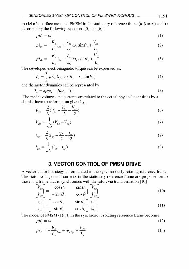
model of a surface mounted PMSM in the stationary reference frame (α-β axes) can be
described by the following equations [5] and [6],
rrp (1)
s
s
rr
s
m
s
s
s
sL
V
Li
L
Rpi
sin (2)
s
s
rr
s
m
s
s
s
sL
V
Li
L
Rpi
cos (3)
The developed electromagnetic torque can be expressed as:
)sincos(2
3rsrsme iipT (4)
and the motor dynamics can be represented by
drre TBJpT (5)
The model voltages and currents are related to the actual physical quantities by a
simple linear transformation given by:
)22
(3
2 csbs
ass
VVVV (6)
)(3
1csbss VVV (7)
)22
(3
2 css
ass
iiii
(8)
)(3
1csbss iii (9)
3. VECTOR CONTROL OF PMSM DRIVE
A vector control strategy is formulated in the synchronously rotating reference frame.
The stator voltages and currents in the stationary reference frame are projected on to
those in a frame that is synchronous with the rotor, via transformation [10]
s
s
rr
rr
qs
ds
V
V
V
V
cossin
sincos (10)
s
s
rr
rr
qs
ds
i
i
i
i
cossin
sincos (11)
The model of PMSM (1)-(4) in the synchronous rotating reference frame becomes
rrp (12)
s
ds
qsrds
s
s
dsL
Vii
L
Rpi (13)
Yehia S. Mohamed 1192
s
qs
s
rm
dsrqs
s
s
qsL
V
Lii
L
Rpi
(14)
Note that the electromagnetic torque can be expressed as:
)(2
3qsdsdsqse iiPT (15)
The stator flux components ),( qsds are in the form
mdssds iL , (16)
qssqs iL (17)
An efficient control strategy of the vector control technique is to make the d-
axis current di zero so that the direct axis stator flux linkage ds becomes dependent
only on the flux linkage by the permanent magnet rotor m . With this control strategy,
the machine model becomes simpler and can be described by the following equations
s
qs
s
rm
qs
s
s
qsL
V
Li
L
Rpi
(19)
J
T
J
B
J
Tp dre
r
(20)
and the electromagnetic torque is proportional to the q-axis stator current as given by
qsTe iKT (21)
Where mT PK 2
3
Equation (21) is similar to the torque equation of a separately excited dc
motor, where qsi corresponds to the armature current of a dc motor. Hence, a precise
torque control of the PMSM is achieved by controlling the q-axis stator current
component qsi .
4. NONLINEAR STATE OBSERVER
An extended nonlinear state observer is used to estimate the PMSM states and the
unknown load torque disturbance. The observer states copies the PMSM model adding
a correction term that works as a driving input and the unknown load torque
disturbance. A new state is added to track a slowly varying load torque [11]. The
torque due to viscosity is incorporated to the disturbance torque dT , so the rB term
does not appear explicitly in the observer. Even though, the disturbance torque dT is
not a constant parameter under the mechanical parameter variations from their nominal
values. If the sampling interval is sufficiently fast as compared with the time, the
variation in viscous friction coefficient, inertia and hence of the unknown disturbance
dT can be assumed to be constant during each sampling interval as [10] and [11].
SENSORLESS VECTOR CONTROL OF PM SYNCHRONOUS…..
1193
0dpT (22)
In order to satisfy convergence conditions, stability, the correction term and
the adaptation law are derived using Lyapunovs theorem [9].
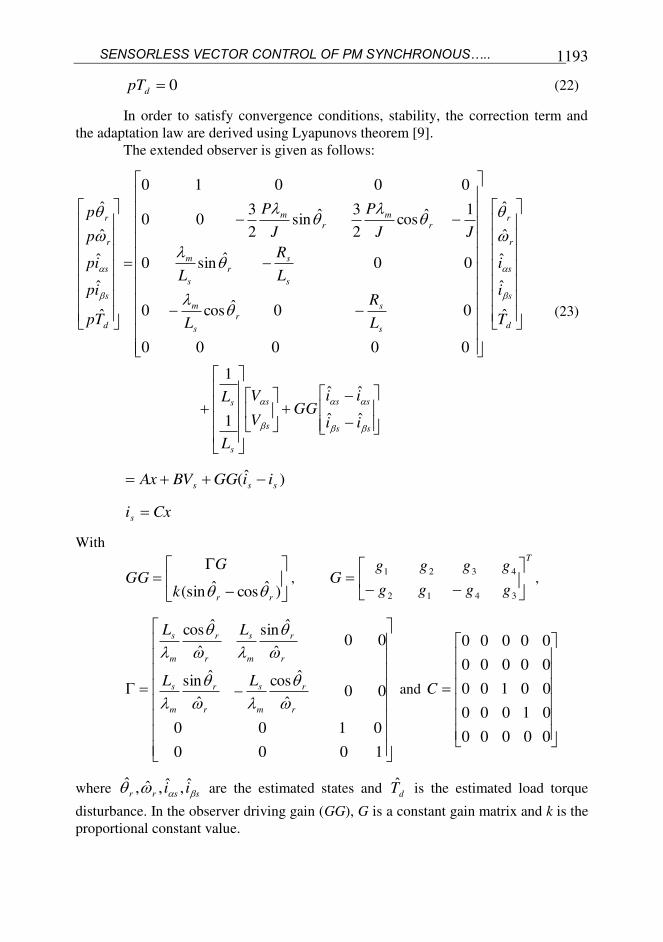
The extended observer is given as follows:
ss
ss
s
s
s
s
d
s
s
r
r
s
s
r
s
m
s
s
r
s
m
r
m
r
m
d
s
s
r
r
ii
iiGG
V
V
L
L
T
i
i
L
R
L
L
R
L
JJ
P
J
P
Tp
ip
ip
p
p
ˆˆ
ˆˆ
1
1
ˆ
ˆ
ˆˆ
ˆ
00000
00ˆcos0
00ˆsin0
1ˆcos2
3ˆsin2
300
00010
ˆ
ˆ
ˆˆ
ˆ
(23)
)ˆ( sss iiGGBVAx
Cxis
With
)ˆcosˆ(sin rrk
GGG
,
T
gggg
ggggG
3412
4321,
1000
0100
00ˆ
ˆcos
ˆ
ˆsin
00ˆ
ˆsin
ˆ
ˆcos
r
r
m
s
r
r
m
s
r
r
m
s
r
r
m
s
LL
LL
and
00000
01000
00100
00000
00000
C
where ssrr ii ˆ,ˆ,ˆ,ˆ are the estimated states and dT is the estimated load torque
disturbance. In the observer driving gain (GG), G is a constant gain matrix and k is the
proportional constant value.
Yehia S. Mohamed 1194
5. NONLINEAR STATE OBSERVER WITH PARAMETER ADAPTATION
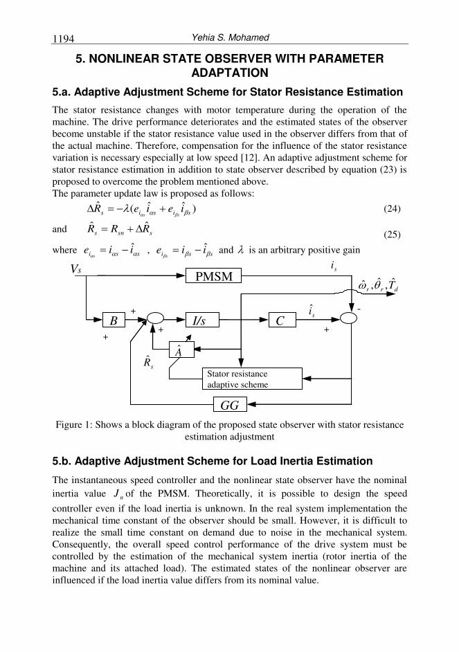
5.a. Adaptive Adjustment Scheme for Stator Resistance Estimation
The stator resistance changes with motor temperature during the operation of the
machine. The drive performance deteriorates and the estimated states of the observer
become unstable if the stator resistance value used in the observer differs from that of
the actual machine. Therefore, compensation for the influence of the stator resistance
variation is necessary especially at low speed [12]. An adaptive adjustment scheme for
stator resistance estimation in addition to state observer described by equation (23) is
proposed to overcome the problem mentioned above.
The parameter update law is proposed as follows:
)ˆˆ(ˆsisis ieieR
ss (24)
and ssns RRR ˆˆ
(25)
where ssi iies
ˆ , ssi iies
ˆ and is an arbitrary positive gain
Figure 1: Shows a block diagram of the proposed state observer with stator resistance
estimation adjustment
5.b. Adaptive Adjustment Scheme for Load Inertia Estimation
The instantaneous speed controller and the nonlinear state observer have the nominal
inertia value nJ of the PMSM. Theoretically, it is possible to design the speed
controller even if the load inertia is unknown. In the real system implementation the
mechanical time constant of the observer should be small. However, it is difficult to
realize the small time constant on demand due to noise in the mechanical system.
Consequently, the overall speed control performance of the drive system must be
controlled by the estimation of the mechanical system inertia (rotor inertia of the
machine and its attached load). The estimated states of the nonlinear observer are
influenced if the load inertia value differs from its nominal value.
C I/s
Stator resistance
adaptive scheme
GG
PMSM Vs
B
A
si
si
+
-
+ +
+
sR
drr T,ˆ,ˆ
SENSORLESS VECTOR CONTROL OF PM SYNCHRONOUS…..
1195
The inertia of the mechanical load condition is estimated in this paper using
the periodic test signal according to the relationship of the mathematical orthogonality
of the disturbance between the periodic signal and its derivative.
For the purpose of this estimation, the disturbance load torque observer
corresponding to nominal inertia value ndT can be modified as:
)()()()(ˆ tTtBtpJtT errnnd (26)
T
e
qsqsK
tTtipi
)()( (27)
Where is the observer pole ( >0)
The load inertia variation is caused by the variation of machine load condition
or an estimated error of load inertia and it is expressed as:
nJJJ
From equations (26) and (27) above, the derivative of the estimated
disturbance torque is derived as:
0))()(()(ˆ)(ˆ crrdd TtBtJptTtTp (28)
where cT is the constant load torque
Using equations (26)-(28) the estimated disturbance load torque for any load
condition can be obtained as:
qsTrrd iKtBtJptT )()()(ˆ (29)
The angular speed of the PMSM drive system imposed by the periodic speed
command, the can be expressed as:
t
Ttt rr 0)()(lim
The inner product of arbitrary signals can be confined as follows:
kT
Tk
baba dttt)1(
)()(, (30)
From equation (30), the inner products of rr p and rqs pi can be written
as follows:
k
dttpt
kT
Tk
rr
)1(
0)()(lim
k
dttpti
kT
Tk
rqs
)1(
0)()(lim
From above relations, the convergence of the estimated load inertia can be
evaluated as follows:
Yehia S. Mohamed 1196
kT
Tk
kT
Tk
rqsTrr
kT
Tk
r
kT
Tk
rd dttptiKdttptBdttpJdttptT)1( )1()1(
2
)1(
)()()()()()()(ˆ
kk
dttpJdttptT
kT
Tk
r
kT
Tk
rd
)1(
2
)1(
)()()(ˆ
k
dttp
dttpT
Jk
Tk
r
k
Tk
rd
)1(
2
)1(
)(ˆ
)(ˆˆ
limˆ
(31)
Consequently, the estimated load inertia J value converges to the actual one
due to the existence relationship of the orthogonality between the periodic forward-
reverse speed command and its derivative.
0)(),()( *** tTtt rrr
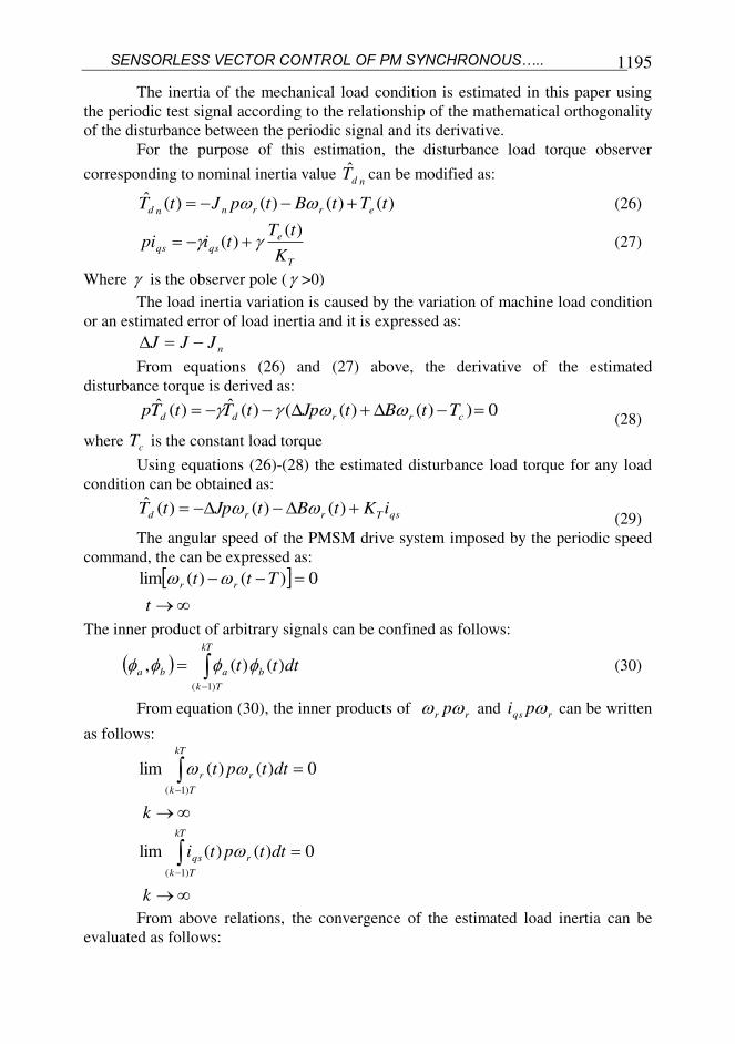
Figure 2 shows the block diagram of the estimated load inertia variation of the
mechanical system described by equation (31)
Figure 2: Block diagram of the load inertia estimation
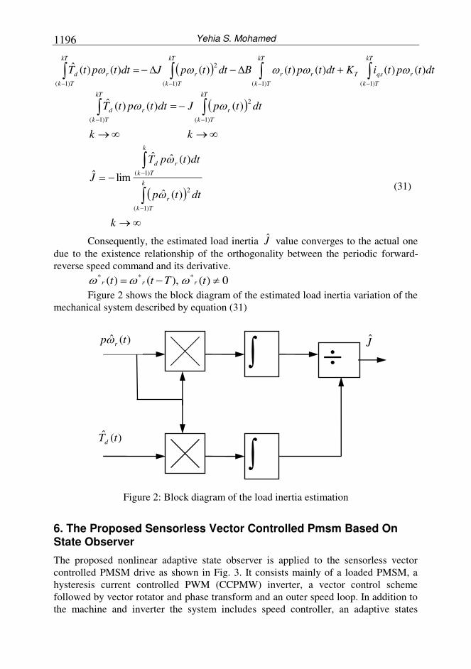
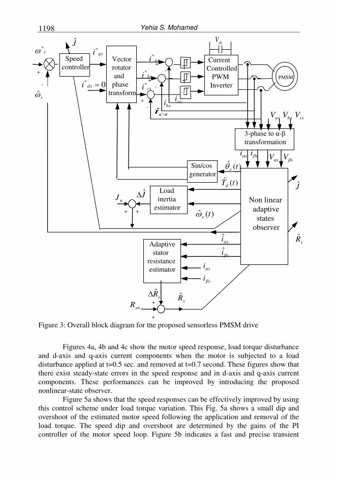
6. The Proposed Sensorless Vector Controlled Pmsm Based On State Observer
The proposed nonlinear adaptive state observer is applied to the sensorless vector
controlled PMSM drive as shown in Fig. 3. It consists mainly of a loaded PMSM, a
hysteresis current controlled PWM (CCPMW) inverter, a vector control scheme
followed by vector rotator and phase transform and an outer speed loop. In addition to
the machine and inverter the system includes speed controller, an adaptive states
)(ˆ tTd
)(ˆ tp r
J
SENSORLESS VECTOR CONTROL OF PM SYNCHRONOUS…..
1197
observer, an adaptive stator resistance and load inertia estimators. The speed controller
generates the torque component current command qsi*
from the speed error between
the estimated motor speed and the command speed. The estimated speed is obtained
from the nonlinear adaptive states observer. Measurements of two stator phase
voltages and currents are transformed to α- and β- components and used in an adaptive
states observer. The nonlinear adaptive states observer is used to estimate PMSM
states ( rss ii ˆ,ˆ,ˆ and r ) and the unknown load torque disturbance dT . This
observer with stator resistance and load inertia estimations is used for adapting the
parameters of speed controller. The vector rotator and phase transform in Fig. 3 is used
for transforming the stator current components command ( qsi*
and 0* dsi ) to the
three phase stator current commands ( bsas ii** , and csi
*) by using the estimated rotor
angle position r . The hysteresis current control compares the stator current
commands to the actual currents of the machine and switches the inverter transistors in
such a way that the commanded currents are obtained.
6. SIMULATION RESULTS AND DISCUSSION
The proposed observer-based controller with disturbance torque estimation of Fig. 3 is
verified by means of simulations. The nominal parameters and specifications of a
PMSM used for the simulations are listed in Table I.
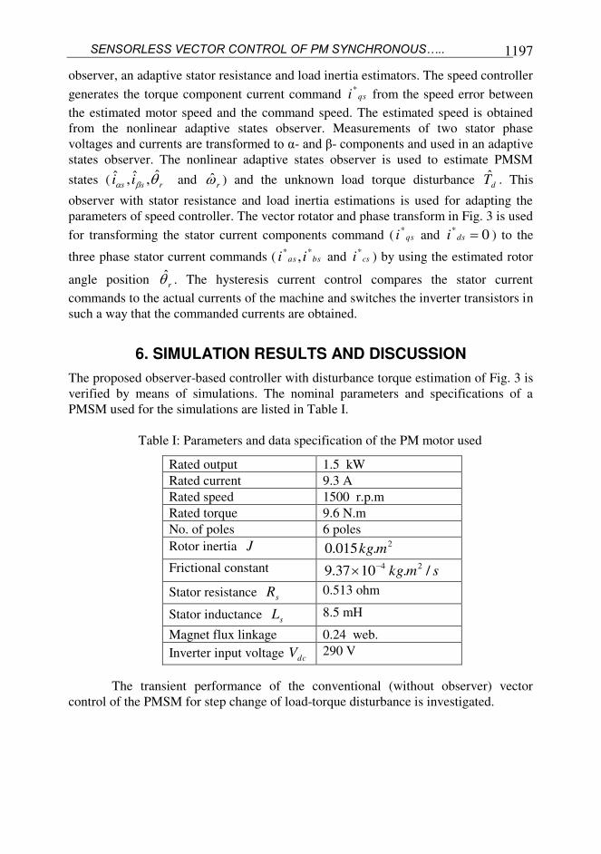
Table I: Parameters and data specification of the PM motor used
Rated output 1.5 kW
Rated current 9.3 A
Rated speed 1500 r.p.m
Rated torque 9.6 N.m
No. of poles 6 poles
Rotor inertia J 2.015.0 mkg
Frictional constant smkg /.1037.9 24
Stator resistance sR 0.513 ohm
Stator inductance sL 8.5 mH
Magnet flux linkage 0.24 web.
Inverter input voltage dcV 290 V
The transient performance of the conventional (without observer) vector
control of the PMSM for step change of load-torque disturbance is investigated.
Yehia S. Mohamed 1198
Figure 3: Overall block diagram for the proposed sensorless PMSM drive
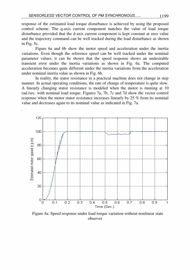
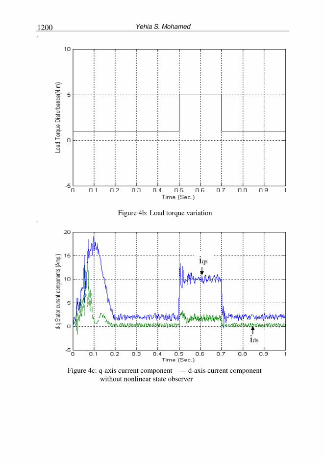
Figures 4a, 4b and 4c show the motor speed response, load torque disturbance
and d-axis and q-axis current components when the motor is subjected to a load
disturbance applied at t=0.5 sec. and removed at t=0.7 second. These figures show that
there exist steady-state errors in the speed response and in d-axis and q-axis current
components. These performances can be improved by introducing the proposed
nonlinear-state observer.
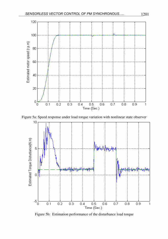
Figure 5a shows that the speed responses can be effectively improved by using
this control scheme under load torque variation. This Fig. 5a shows a small dip and
overshoot of the estimated motor speed following the application and removal of the
load torque. The speed dip and overshoot are determined by the gains of the PI
controller of the motor speed loop. Figure 5b indicates a fast and precise transient
)(ˆ tr
qsi*
s
s
i
i
ss ii ss VV
)(ˆ tTd
s
s
i
i
ˆ
ˆ
0* dsi
J
J nJ
+ +
sR
PMSM
3-phase to α-β
transformation
Non linear
adaptive
states
observer
Speed
controller
Sin/cos
generator
Load
inertia
estimator
Adaptive
stator
resistance
estimator
+
+
sR sR
snR
r*
r
+
J
+
-
dcV
Current
Controlled
PWM
Inverter
)(ˆ tr
csbsas VVVcsi
asi
asi*
bsi*
csi*
Vector
rotator
and
phase
transform
bsi +
-
+
-
+
-
SENSORLESS VECTOR CONTROL OF PM SYNCHRONOUS…..
1199
response of the estimated load torque disturbance is achieved by using the proposed
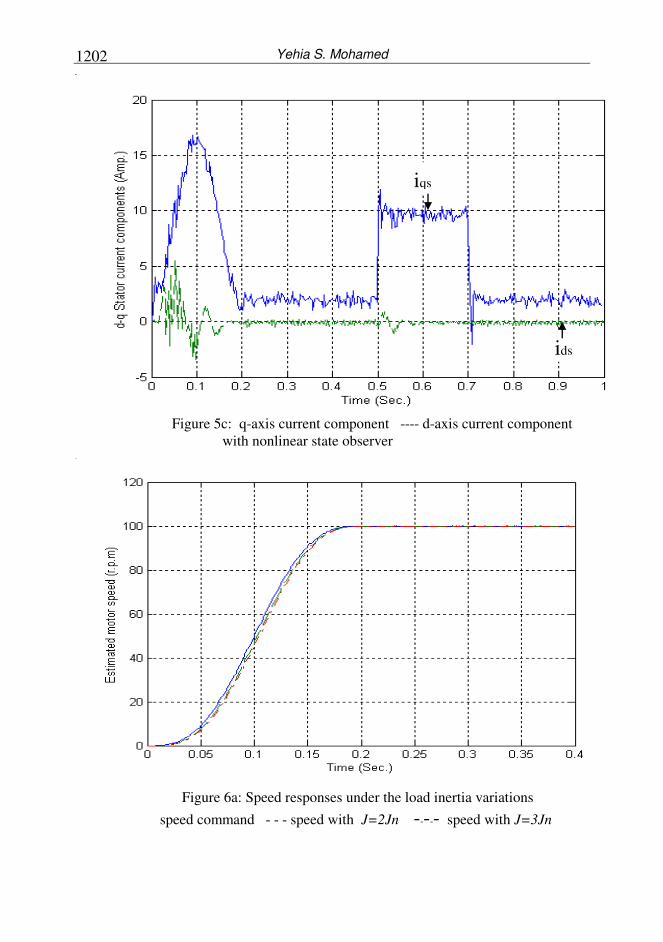
control scheme. The q-axis current component matches the value of load torque
disturbance provided that the d-axis current component is kept constant at zero value
and the trajectory command can be well tracked during the load disturbance as shown
in Fig. 5c.
Figure 6a and 6b show the motor speed and acceleration under the inertia
variations. Even though the reference speed can be well tracked under the nominal
parameter values, it can be shown that the speed response shows an undesirable
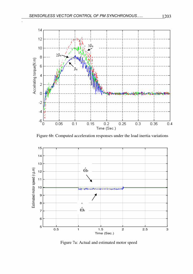
transient error under the inertia variations as shown in Fig. 6a. The computed
acceleration becomes quite different under the inertia variations from the acceleration
under nominal inertia value as shown in Fig. 6b.
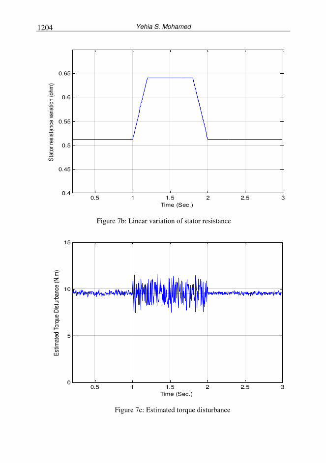
In reality, the stator resistance in a practical machine does not change in step
manner. In actual operating conditions, the rate of change of temperature is quite slow.
A linearly changing stator resistance is modeled when the motor is running at 10
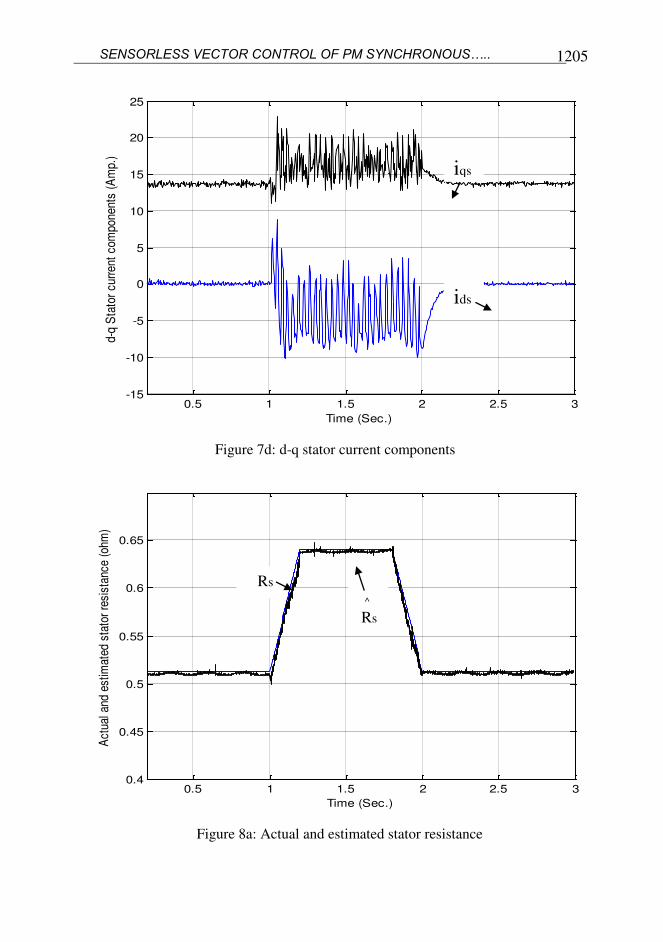
rad./sec. with nominal load torque. Figures 7a, 7b, 7c and 7d show the vector control
response when the motor stator resistance increases linearly by 25 % from its nominal
value and decreases again to its nominal value as indicated in Fig. 7a.
Figure 4a: Speed response under load torque variation without nonlinear state
observer
Yehia S. Mohamed 1200
Figure 4b: Load torque variation
Figure 4c: q-axis current component --- d-axis current component
without nonlinear state observer
ids
iqs
SENSORLESS VECTOR CONTROL OF PM SYNCHRONOUS…..
1201
Figure 5a: Speed response under load torque variation with nonlinear state observer
Figure 5b: Estimation performance of the disturbance load torque
Yehia S. Mohamed 1202
Figure 5c: q-axis current component ---- d-axis current component
with nonlinear state observer
Figure 6a: Speed responses under the load inertia variations
speed command - - - speed with J=2Jn ----- speed with J=3Jn
ids
iqs
SENSORLESS VECTOR CONTROL OF PM SYNCHRONOUS…..
1203
Figure 6b: Computed acceleration responses under the load inertia variations
0.5 1 1.5 2 2.5 35
6
7
8
9
10
11
12
13
14
15
Time (Sec.)
Est
imat
ed m
otor
spe
ed (
r.p.
m)
Figure 7a: Actual and estimated motor speed
3Jn
2Jn
Jn
^
ώr
ώr
Yehia S. Mohamed 1204
0.5 1 1.5 2 2.5 30.4
0.45
0.5
0.55
0.6
0.65
Time (Sec.)
Sta
tor
resi
stan
ce v
aria
tion
(ohm
)
Figure 7b: Linear variation of stator resistance
0.5 1 1.5 2 2.5 30
5
10
15
Time (Sec.)
Est
imat
ed T
orqu
e D
istu
rban
ce (
N.m
)
Figure 7c: Estimated torque disturbance
SENSORLESS VECTOR CONTROL OF PM SYNCHRONOUS…..
1205
0.5 1 1.5 2 2.5 3-15
-10
-5
0
5
10
15
20
25
Time (Sec.)
d-q
Sta
tor
curr
ent
com
pone
nts
(Am
p.)
Figure 7d: d-q stator current components
0.5 1 1.5 2 2.5 30.4
0.45
0.5
0.55
0.6
0.65
Time (Sec.)
Act
ual a
nd e
stim
ated
sta
tor
resi
stan
ce (
ohm
)
Figure 8a: Actual and estimated stator resistance
ids
iqs
^
Rs
Rs
Yehia S. Mohamed 1206
0.5 1 1.5 2 2.5 35
6
7
8
9
10
11
12
13
14
15
Time (Sec.)
Est
imat
ed m
otor
spe
ed (
r.p.
m)
Figure 8b: Actual and estimated motor speed with stator resistance estimator
0.5 1 1.5 2 2.5 30
5
10
15
Time (Sec.)
Est
imat
ed T
orqu
e D
istu
rban
ce (
N.m
)
Figure 8c: Estimated torque disturbance with stator resistance estimator
SENSORLESS VECTOR CONTROL OF PM SYNCHRONOUS…..
1207
0.5 1 1.5 2 2.5 3-15
-10
-5
0
5
10
15
20
25
Time (Sec.)
d-q
Sta
tor
curr
ent
com
pone
nts
(Am
p.)
Figure 8d: d-q stator current components with stator resistance estimator
0.5 1 1.5 2 2.5 30
0.005
0.01
0.015
0.02
0.025
0.03
0.035
0.04
0.045
0.05
Time (Sec.)
Iner
tia v
aria
tion
and
its e
stim
atio
n (k
g.m
eter
squ
are)
Figure 9a: Inertia variation and its estimation
ids
iqs
Yehia S. Mohamed 1208
0.5 1 1.5 2 2.5 3-6
-4
-2
0
2
4
6
Time (Sec.)
Est
imat
ed m
otor
spe
ed (
r.p.
m)
Figure 9b: Estimated speed response and its reference
0.5 1 1.5 2 2.5 3-20
-15
-10
-5
0
5
10
15
20
Time (Sec.)
Est
imat
ed T
orqu
e D
istu
rban
ce (
N.m
)
Figure 9c: Estimated disturbance torque
SENSORLESS VECTOR CONTROL OF PM SYNCHRONOUS…..
1209
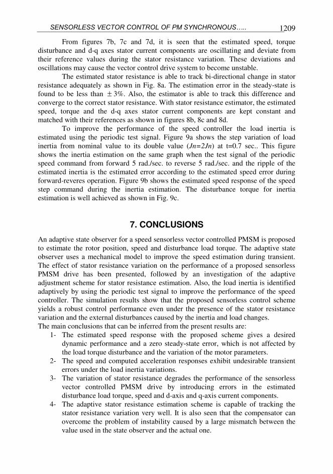
From figures 7b, 7c and 7d, it is seen that the estimated speed, torque
disturbance and d-q axes stator current components are oscillating and deviate from
their reference values during the stator resistance variation. These deviations and
oscillations may cause the vector control drive system to become unstable.
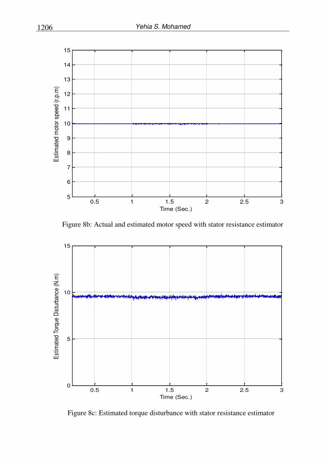
The estimated stator resistance is able to track bi-directional change in stator
resistance adequately as shown in Fig. 8a. The estimation error in the steady-state is
found to be less than 3%. Also, the estimator is able to track this difference and
converge to the correct stator resistance. With stator resistance estimator, the estimated
speed, torque and the d-q axes stator current components are kept constant and
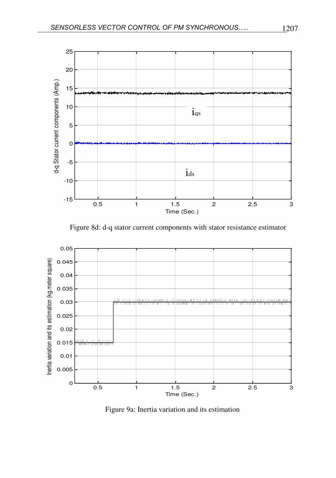
matched with their references as shown in figures 8b, 8c and 8d.
To improve the performance of the speed controller the load inertia is
estimated using the periodic test signal. Figure 9a shows the step variation of load
inertia from nominal value to its double value (Jn=2Jn) at t=0.7 sec.. This figure
shows the inertia estimation on the same graph when the test signal of the periodic
speed command from forward 5 rad./sec. to reverse 5 rad./sec. and the ripple of the
estimated inertia is the estimated error according to the estimated speed error during
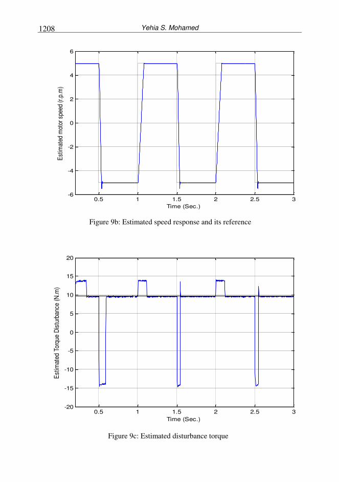
forward-reveres operation. Figure 9b shows the estimated speed response of the speed
step command during the inertia estimation. The disturbance torque for inertia
estimation is well achieved as shown in Fig. 9c.
7. CONCLUSIONS
An adaptive state observer for a speed sensorless vector controlled PMSM is proposed
to estimate the rotor position, speed and disturbance load torque. The adaptive state
observer uses a mechanical model to improve the speed estimation during transient.
The effect of stator resistance variation on the performance of a proposed sensorless
PMSM drive has been presented, followed by an investigation of the adaptive
adjustment scheme for stator resistance estimation. Also, the load inertia is identified
adaptively by using the periodic test signal to improve the performance of the speed
controller. The simulation results show that the proposed sensorless control scheme
yields a robust control performance even under the presence of the stator resistance
variation and the external disturbances caused by the inertia and load changes.
The main conclusions that can be inferred from the present results are:
1- The estimated speed response with the proposed scheme gives a desired
dynamic performance and a zero steady-state error, which is not affected by
the load torque disturbance and the variation of the motor parameters.
2- The speed and computed acceleration responses exhibit undesirable transient
errors under the load inertia variations.
3- The variation of stator resistance degrades the performance of the sensorless
vector controlled PMSM drive by introducing errors in the estimated
disturbance load torque, speed and d-axis and q-axis current components.
4- The adaptive stator resistance estimation scheme is capable of tracking the
stator resistance variation very well. It is also seen that the compensator can
overcome the problem of instability caused by a large mismatch between the
value used in the state observer and the actual one.
Yehia S. Mohamed 1210
5- The estimated load inertia tracks well the step variation in the load inertia
during forward-reverse speed command. Also, the estimated speed and
disturbance load torque are achieved well during the inertia estimation
REFERENCES
[1] F. Blaschke, " The principle of Field Orientation as Applied to the New
Transvector Closed Loop Control System for Rotating Field Machines", Simens
Review 1972.
[2] M. A. El-Sharkawi, A. A. El-Samahy and M. L. El-Sayed, " High Performance
Drive of DC Brushless Motors Using Neural Network", IEEE Trans. on Energy
Conversion, Vol. 9, No. 2, pp. 317-322, 1994.
[3] B. Le Pioufle, " Comparison of Speed Nonlinear Control Strategies for the
Synchronous Servomotor, " Elect. Machine Power System, Vol. 21, pp. 151-169,
1993.
[4] M. Bodson, J. Chiasson, R. Novocna and R. Rcawaski " High Performance
Nonlinear Feedback Control of a Permanent Synchronous Stepper Motor," IEEE
Trans. on Control Systems Technology, Vol. 1, pp.5-13, 1993.
[5] J. Kim and S. Sul , " High Performance PMSM Drive Without Rotational Position
Sensors Using Reduced Order Observer," in Proc. 1995 IEEE Transaction
Industry Applications Society Annual Meeting (IAS'95), Vol. 1, Orlando USA,
pp. 75-82, October 1995.
[6] R. Sepe and J. Lang," Real Time Observer Based (Adaptive) Control of a
Permanent Synchronous Motor Without Mechanical Sensors," IEEE Transaction
on Industry Applications , Vol. 28, pp. 1345-1352, 1992.
[7] J. Shouse and D. Taylor, " Sensorless Velocity Control of Permanent Magnet
Synchronous Motors, " In Proc. 33rd
IEEE Conference on Decision and Control
(CDC'94), Lake Buena Vista. USA, pp. 1844-1849, 1994.
[8] K. H. Kim, I. C. Baik, S. K. Chung and M. J. Youn, " Robust Speed Control of
brushless DC Motor Using Adaptive Input-Output Linearization Technique,"
Proc. IEE-Elect. Power Application Vol. 144, No. 6, pp. 469-475, 1997.
[9] I. C. Baik, K. H. Kim and M. J. Youn, " Robust Nonlinear Speed Control of PM
synchronous Motor Using Boundary Layer Integral Sliding Mode Control
Technique," IEEE Transaction Control System Technology, Vol. 8, pp. 47-54,
Jan. 2000.
[10] J. Solsona, M. I. Valla and C. Muravchik," Nonlinear Control of a Permanent
Magnet Synchronous Motor With Disturbance Torque Estimation", IEEE
Transaction on Energy Conversion, Vol. 15, pp. 163-168, June 2000.
[11] G. Buja, R. Menis, and M. I. Valla. "Disturbance Torque Estimation in a
Sensorless DC Drive," IEEE Trans. On Industrial Electronic, Vol. 42, pp. 351-
357, 1995
[12] M. Rashed, P. F. A. MacConnell, A. F. Stronach and P. Acarnley, "Sensorless
Indirect Rotor Field Orientation Speed Control of a Permanent Magnet
Synchronous Motor With Stator Resistance Estimation", IEEE Transaction on
Industrial Electronics, Vol. 54, No. 3, June 2007.

SENSORLESS VECTOR CONTROL OF PM SYNCHRONOUS…..
1211
محرك م م ااتجاهي تح زامن ذو مغناطيس دائم بدون مقياستامقيمذلسرعة و لعزم ا مفاجئ تغير ا ك باستخدام ماحظ مائم مع ا
زا ن و غناةد را ي دم ور ح ا البح ي دم ري ة دم ة لرد ر لا يحلي ال مة ل ة ح ي ذه - .أايلاه غد ع ف برون ا يمراي مداس لا ة ويي ا يل ا ذل ع نظاي اليحلي
ي ي ا يمراي ح ظ امة ذو يواب ر مد ة بة دم ة ة لاحض و ا و ع الع و ال روا - لي ش ا يمراي ح ا ار وال ة و لبار يدا الع و اليابر ولذل اليغد ال فالئ ف زوي الح
دلاندلدة.وذل با يمراي الي رري ي يمد دي ماو ة الع و الياب ر الي ييغد ع ر ل ة الح ا لا ح ول ذل -
ي ي يح دن م وا حل ي ال ة وذل بيمد دي لمد ة زي المض و ال ذاي وأد اة دم ة ال يحلي ال ي ال غوبة. اميبا رو دة لا ة إشا لاح با يمراي
باليغد ف يوابر ال ح . واديا يالة دمة ال مي حة يلع نظاي ال ح دع برقة و ماو ة -ل با يمراي الني ا ر النظ د ة ذالم وا الردنا دلد ة وال يم لانظ اي ال مي ي ي ا ويو دح ا و -
الي يي الحضو اد ا ن الحا ب.