Embed Size (px)
Citation preview

3-Jaw Chuck Rotary Attachment for Fusion
The 3-Jaw chuck style rotary is an extremely versatile tool for marking and engraving cylindrical
objects. It comes with a variety of interchangeable components that make it easy to hold different
sized and shaped cylinders.
There are two basic setups:
1) 3-Jaw Chuck
2) Fixture plates
This photo shows the basic setup with the 3-jaw
chuck on the left and the centering fixture on the
right.
This photo shows the 3-Jaw style rotary attachment
with the large fixture plates installed.
Fixture plates and additional components:
1) Small fixture plates (2 each)
2) Large fixture plates (2 each)
3) Idle-side centering fixture (1 each)
4) Plate spindle (1 each)
5) Plate fixture thumb screws (2 each)
6) 3-Jaw tightening pins (2 each)

7) 3” Lens for CO2 Fusion only. Always install this 3” lens
whenever using the 3-Jaw chuck style rotary in the CO2 Fusion. Use
the standard 2” lens for all non-3-Jaw chuck rotary jobs.
CO2 Fusion
The CO2 Fusion 3-Jaw rotary attachment requires the use a 3” lens. The crash bar
on the standard 2” lens on the CO2 Fusion interferes with the rotary attachment
and cannot be used.
The FiberMark Fusion does not need a different lens because it already
incorporates a 5” lens as standard equipment.
Remove the standard 2” lens. The 2” lens
incorporates the crash bar and the air assist
tube.
Install the 3” lens. The 3” lens does not
include the crash bar or air assist tube.
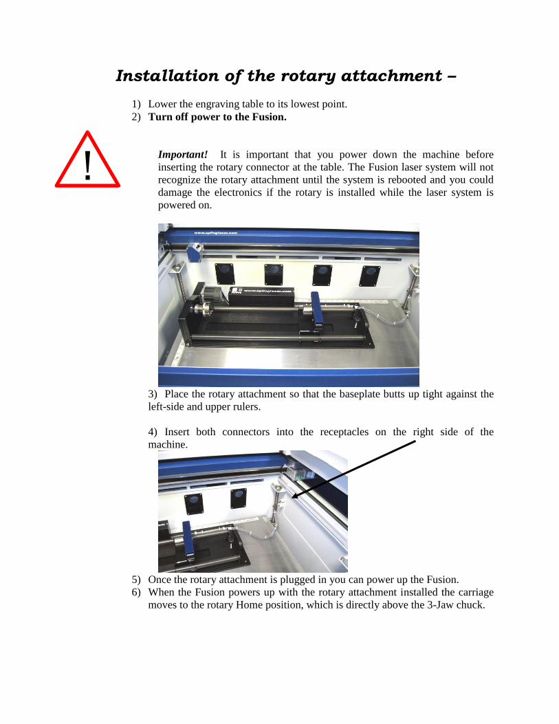
Installation of the rotary attachment –
1) Lower the engraving table to its lowest point.
2) Turn off power to the Fusion.
Important! It is important that you power down the machine before
inserting the rotary connector at the table. The Fusion laser system will not
recognize the rotary attachment until the system is rebooted and you could
damage the electronics if the rotary is installed while the laser system is
powered on.
3) Place the rotary attachment so that the baseplate butts up tight against the
left-side and upper rulers.
4) Insert both connectors into the receptacles on the right side of the
machine.
5) Once the rotary attachment is plugged in you can power up the Fusion.
6) When the Fusion powers up with the rotary attachment installed the carriage
moves to the rotary Home position, which is directly above the 3-Jaw chuck.

Initial Setup (Setting Home - First time use only).
New installations may need to establish the Rotary Home Position.
The following instructions show how to set a Home position for the 3-Jaw rotary attachment. For
most users this is not necessary because they set a new Home position for every rotary job they
run using the Center-Center engraving feature in the driver. Center-Center engraving is
explained later in these instructions. The concept of why Center-Center is used is hard to explain,
but rest assured that it will become obvious on your very first 3-Jaw chuck rotary job.
Install the rotary and power up the system. The system will go through its standard power up
sequence. The carriage will come to rest directly over the rotary instead of in the upper left
corner and the table will move to its lowest position.
Turn on the red dot pointer (you will need to raise the table to focus the red dot pointer). The red
dot will show you the location of your Home position. For proper operation most users set the
Home position at the edge of either the clamp or the jaws. However, depending on your specific
application it can be set anywhere you want it to be. Our experience shows that most users prefer
the edge of the jaws.
Your X-Home position defines the left edge of
your page in your graphics software.
To establish the Rotary Home setting at the
edge of the jaws we will use the red dot pointer
to show us where our Home position is and
then how much we need to adjust our settings.
1. Turn on the red dot pointer from the Fusion keypad.
2. Go to Jog on the Fusion keyboard.
3. Use the Joystick to move the carriage so that the red dot pointer is at the
front edge of the jaws or the clamp. Make sure the red dot is also centered
front to back. This exercise is easier to perform if you have a cylinder in
place.
4. The LCD on the keypad shows a digital readout of the location of the red
dot pointer. The number displayed on the left is the X-Axis, the number on
Edge of jaw.
Edge of chuck.

the right is the Y-axis. Write down these two numbers including the plus
or minus sign associated with each.
5. Go to Config on the Fusion keypad.
6. Tilt the Joystick down to scroll to the X R Home menu. New installations
will show a value of 0.000.
7. Center-Click the Joystick. A flashing cursor will appear below the number
displayed. Tilt the Joystick up or down to increment or decrement the
number so that it matches the number you recorded above for the red dot
pointer X-axis value.
8. Press the Go button to Save the setting.
9. Now, tilt the Joystick down to scroll to the Y R Home menu. New
installations will show a value of 0.000.
10. Center-Click the Joystick. A flashing cursor will appear below the number
displayed. Tilt the Joystick to increment or decrement the number so that
it matches the number you recorded above for the red dot pointer Y-axis
value.
11. Press the Go button to Save the setting.
12. Tilt the Joystick up to scroll back to the Restore XY Home menu item.
13. Center-Click to save the new X and Y values. The carriage will now move
back and to the left to establish a new Home position. Your red dot pointer
should now be located at its new location.
Once you have set and saved the X and Y rotary Home position you should not
have to set it again, but you can always use the procedure above to adjust your
Home position.
Additional notes about setting a Home position on the Rotary Attachment
Many users do not worry about establishing a formal Home position on the clamping style
rotary. Many users find that each new rotary job uses an entirely different clamping method than
the last and setting a fixed Home position just isn’t important. Instead, they use the Center-
Center feature in the driver and establish a new home position for each job. This is easy to do.
1) Clamp your cylinder into the rotary attachment.
2) Focus on your cylinder.
3) Turn on the Red dot pointer.
4) Use the Jog feature to move the red dot to a point along your cylinder that defines the
center point of your mark.
5) Single center-click to set that point as your home position.

6) Use the Center-Center feature in the
driver when you are ready to print.
For more information on the Center-
Center feature please refer to Using the
Driver section in your owner’s manual.
Using the Rotary Attachment
Important notes about the 3-Jaw rotary:
There are speed limitations in Vector mode based on cylinder diameter. The
driver will display the maximum speed setting that can be used for a given
diameter. Your Power setting will need to be adjusted according to the speed.
The 3-Jaw style rotary was designed to rotate cylinders that range in size from
0.040” (12.7 mm) to approximately 7” (76.2 mm) in diameter. However, from a
practical point-of-view, it is difficult to produce a legible mark on cylinders that
are smaller than .080” (2 mm).
Measure your Cylinder
Measure your cylinder. The cylinder diameter will
be used in the print driver.
Adjust the rotary for cylinder length
Depress the blue anodized idle-side handle to move the
support mechanism left or right to accommodate
different length cylinders. There are photos later in this
section that show the different configurations available
for the Y-Axis idle side support.

Clamp your Cylinder
Insert your cylinder into the 3-jaw chuck and tighten the chuck so the cylinder is held firmly in
place.
You will need to use the two tightening pins that are
provided with the chuck in order to clamp the cylinder
tightly into place.
Cylinders can be held
from the outside
diameter or the inside
diameter.
The chuck jaws can be
flipped from Standard mode to Wide mode (180 degrees) to accommodate larger radius
cylinders.
Pay particular attention to aligning the numbers as shown on the diagram when flipping the jaws!
Failure to align the correct jaw in the correct slot will result in uneven spacing of the jaws when
they are tightened.
Notice that there is a stamped number on each side of each jaw and next to each slot. For wide-radius
turning, simply remove jaws 1 and 3, flip them, and then insert jaw 1 into slot 3 and jaw 3 into slot 1.
Standard Wide
Cam
JawSlot

Remove jaw 2, flip it and return it to slot 2. The jaws do not need to be inserted all the way just yet. You
will need to rotate the cam to capture the jaws in ascending order (1,2,3). Rotate the cam so that it catches
jaw 1 first, then jaw 2, then jaw 3.
3-Jaw chuck diameter capacities: The 3-jaw chuck allows four different ways to hold your object based on cylinder diameter and
whether you are holding it from the inside or outside diameter.
Jaws in Standard mode Jaws in Wide mode
Piece held from inside diameter.
.875 inch to 3 inches (22.2 to 76.2 mm)
2.125 inch to 3.125 inches (54 to 79.4 mm)
Piece held from outside diameter.
0.040 inch to 1.25 inches (2.54 to 31.7 mm)
1 inch to 3 inches (25.4 to 76.2 mm)
Set the Cylinder Diameter in the Driver
With the rotary installed, the diameter set, and the cylinder held tightly in place,
you are ready to print.
Select the 3-Jaw
Chuck option in the
driver.
Notice that for small
diameter cylinders
the driver limits the
Vector speed in
Vector mode only.
Larger diameter
cylinders do not have
speed limitations.
Focus

With your cylinder in place on
the rotary attachment, place the
focus gage on the lens carriage
and then scroll to Focus mode on
the Fusion keyboard. The
carriage will move back after
one second so that the focus gage
is centered over your cylinder.
When you are finished focusing press the Reset button on the Keypad. The lens
carriage will go back to its standard rotary Home position. You are now ready to
start the job.
Additional notes about focusing with the rotary.
The 3-Jaw chuck style rotary was designed to use manual focusing only. While
Auto focus can be used, it is impractical for everyday use.
When you are in Focus mode the entire x-beam and carriage can be moved by
hand. Normally, users will move only the carriage to a point along the long axis to
focus. It is uncommon, but occasionally users will move the entire x-beam back
and forth by hand. Use caution when moving the x-beam!
After you have finished focusing, pressing any button on the keypad will reset the
carriage back to its standard rotary Home position.
The standard sub-menu items are available in Rotary Focus mode:
GO 0 MOVEOUT
SET 0 RESTORE

Artwork Setup Set up a custom page size in your engraving software that will accommodate the
length and circumference of your cylinder. To set up your page in Corel, measure
the length of the cylinder you are engraving. Use this as the minimum size of the
horizontal dimension of your page. Measure the diameter of the cylinder and
multiply this number by Pi (3.1416) to determine the circumference of the
cylinder. Use the circumference as the minimum size of the vertical dimension of
your page.
The actual size of the page is not overly important. If you have a cylinder that’s
5.23 inches long with a circumference of 2.35 inches, use a page that’s slightly
larger, say, 6” x 3”.
It’s important that you set up your artwork so
the top of the artwork is as close to the top of
the page as you can comfortably place it.
Any white space between the top of the page
and your artwork is considered part of the print
job and your cylinder will rotate that amount
until it reaches the first point of engraving.
Rotary Removal
1) Turn off power to the laser.
2) Open the door.
3) Depress the release tabs on the connectors and unplug the connectors.
4) Remove the rotary attachment.
This image shows a page size of 6”
x 3”. The gray inner rectangle
represents the cylinder that is 5.23”
x 2.35”. Insure your artwork fits
within the cylinder size.

Using the Fixture plates and additional rotary components
The 3-Jaw chuck rotary comes with additional attachments that make it easy to hold different
sized and shaped cylinders. The photos below show different configurations that can be used to
hold a wide variety of cylinders. The components can be mixed and matched. There is no single
“correct” method of holding a cylinder.
Attaching the Fixture Plate to the Chuck
Secure a large or small fixture plate to the spindle
using one of the plate thumb screws.
The fixture plate will look like the photo when the
spindle is assembled.
Slide the spindle into the chuck. Make sure the spindle
is fully inserted into the chuck, then secure it using the
chuck tightening pins.
Be sure to check that your home position is where you
need it once the fixture plate has been installed.

Attaching the Idle-Side Centering Fixture
The idle-side centering fixture is used to hold
small diameter cylinders in place. It can be
removed if the fixture plates are required for
larger diameter cylinders. Remove or install it
using the supplied hex wrench.
Attaching the Idle-Side Fixture Plates
The fixture plates can be used on both the chuck
side of the rotary as well as the idle-side. Attach
the plate by placing it on the idle-side spindle and
securing with a thumb screw.
The splines on all the fixture plates can be
reversed to accommodate parts using the
inside diameter (ID) or outside diameter
(OD). To reverse the spline orientation, pull
the spring-loaded splines away from the
plate and rotate them 180 degrees.
This photo shows the small idle-side plate fixture.
The small plate fixture can accommodate sizes up
to 1” in diameter.

Different Configurations for Fixturing Cylinders
This photo shows a typical example of a part that
might be used with the 3-jaw chuck on the left
side and the small idle-side plate fixture on the
right.
This configuration is used when the cylinder
diameter on the right side is too large for the
centering fixture.
This photo shows a typical example of a larger
part that requires a fixture plate on both the left
and the right sides. Notice that the left side fixture
plate is held in place with the 3-jaw chuck.
This photo shows the standard 3-jaw chuck on the
left side and the idle-side centering fixture on the
right. The idle-side centering fixture can
accommodate sizes up to 1” in diameter.
The centering fixture is used to support small
diameter parts that sag when held in place using
only the 3-jaw chuck.
Some parts do not need the idle-side centering
fixture for support and can be held using only the
3-jaw chuck.

Quick Start Guide:
1) Lower the table far enough to accommodate the rotary attachment.
2) Turn off the machine.
3) Plug in the rotary attachment and position it in the upper left corner of the table.
4) Power up your laser.
5) Set up your artwork.
6) Print, and go to the Preferences window to set your laser parameters
a. Select Center-Center engraving mode.
b. Deselect Auto Focus.
c. Select the 3-Jaw chuck option.
d. Input your cylinder diameter.
e. Set your Speed, Power, and other laser parameters.
f. Send the job to the laser.
7) Focus - Most users prefer to manually focus when using the 3-Jaw style rotary.
a. Press the Focus key on the keypad.
b. One second after pressing the Focus key the carriage will move back and to the
right which places the manual focus gage directly over your cylinder.
c. Use the Joystick to move the table up and down to focus on your cylinder.
d. You can move the carriage by hand to focus anywhere along the length of your
cylinder. You can also move the entire X-beam front and back by hand when the
rotary is installed. Use caution when moving the beam by hand.
e. Press any menu key to exit Focus. The carriage and beam will move back to their
Home position.
8) Set Home – Press the Jog function on the keypad.
a. Turn on the red dot pointer.
b. Use the Joystick to move the pointer to the point on your cylinder where you want
your Home position to be located.
c. Center-click the Joystick to set a Home position.
d. If desired, Double Center-click to bring up the standard Jog submenu.
9) Close the top access door.
10) Press the Go key to start your job.