Embed Size (px)
Citation preview
Generator Advanced Concepts
Common Topics, The Practical Side• Machine Output Voltage Equation
• Pitch
• Harmonics
• Circulating Currents when Paralleling
• Reactances and Time Constants
• Three Generator Curves Used for System Coordination – Thermal Damage Curve
– Decrement Curve
– Reactive Capability
• Efficiency
• Parallel Operation
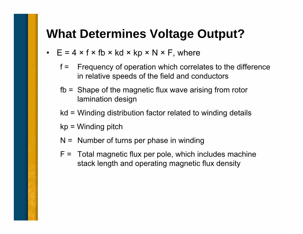
What Determines Voltage Output?• E = 4 × f × fb × kd × kp × N × F, where
f = Frequency of operation which correlates to the difference in relative speeds of the field and conductors
fb = Shape of the magnetic flux wave arising from rotor lamination design
kd = Winding distribution factor related to winding details
kp = Winding pitch
N = Number of turns per phase in winding
F = Total magnetic flux per pole, which includes machine stack length and operating magnetic flux density
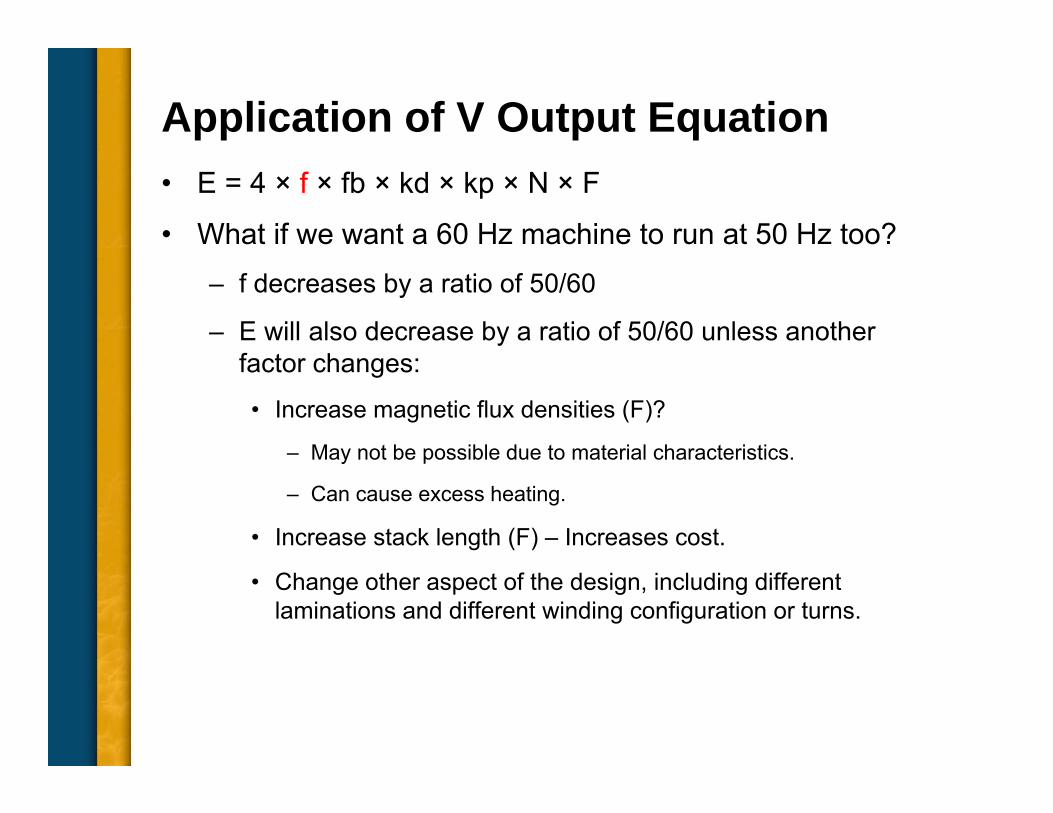
Application of V Output Equation• E = 4 × f × fb × kd × kp × N × F
• What if we want a 60 Hz machine to run at 50 Hz too?– f decreases by a ratio of 50/60
– E will also decrease by a ratio of 50/60 unless another factor changes:
• Increase magnetic flux densities (F)?
– May not be possible due to material characteristics.
– Can cause excess heating.
• Increase stack length (F) – Increases cost.
• Change other aspect of the design, including different laminations and different winding configuration or turns.
Common Topics, The Practical Side• Machine Output Voltage Equation
• Pitch
• Harmonics
• Circulating Currents when Paralleling
• Reactances and Time Constants
• Three Generator Curves Used for System Coordination – Thermal Damage Curve
– Decrement Curve
– Reactive Capability
• Efficiency
• Parallel Operation
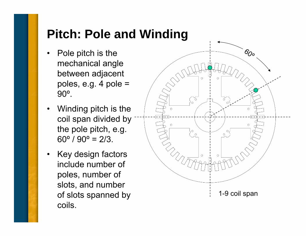
Pitch: Pole and Winding• Pole pitch is the
mechanical angle between adjacent poles, e.g. 4 pole = 90º.
• Winding pitch is the coil span divided by the pole pitch, e.g. 60º / 90º = 2/3.
• Key design factors include number of poles, number of slots, and number of slots spanned by coils.
1-9 coil span
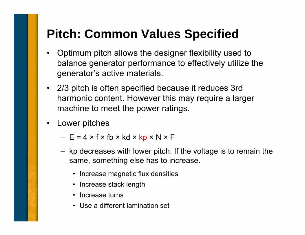
Pitch: Common Values Specified• Optimum pitch allows the designer flexibility used to
balance generator performance to effectively utilize the generator’s active materials.
• 2/3 pitch is often specified because it reduces 3rd harmonic content. However this may require a larger machine to meet the power ratings.
• Lower pitches– E = 4 × f × fb × kd × kp × N × F
– kp decreases with lower pitch. If the voltage is to remain the same, something else has to increase.
• Increase magnetic flux densities • Increase stack length• Increase turns• Use a different lamination set
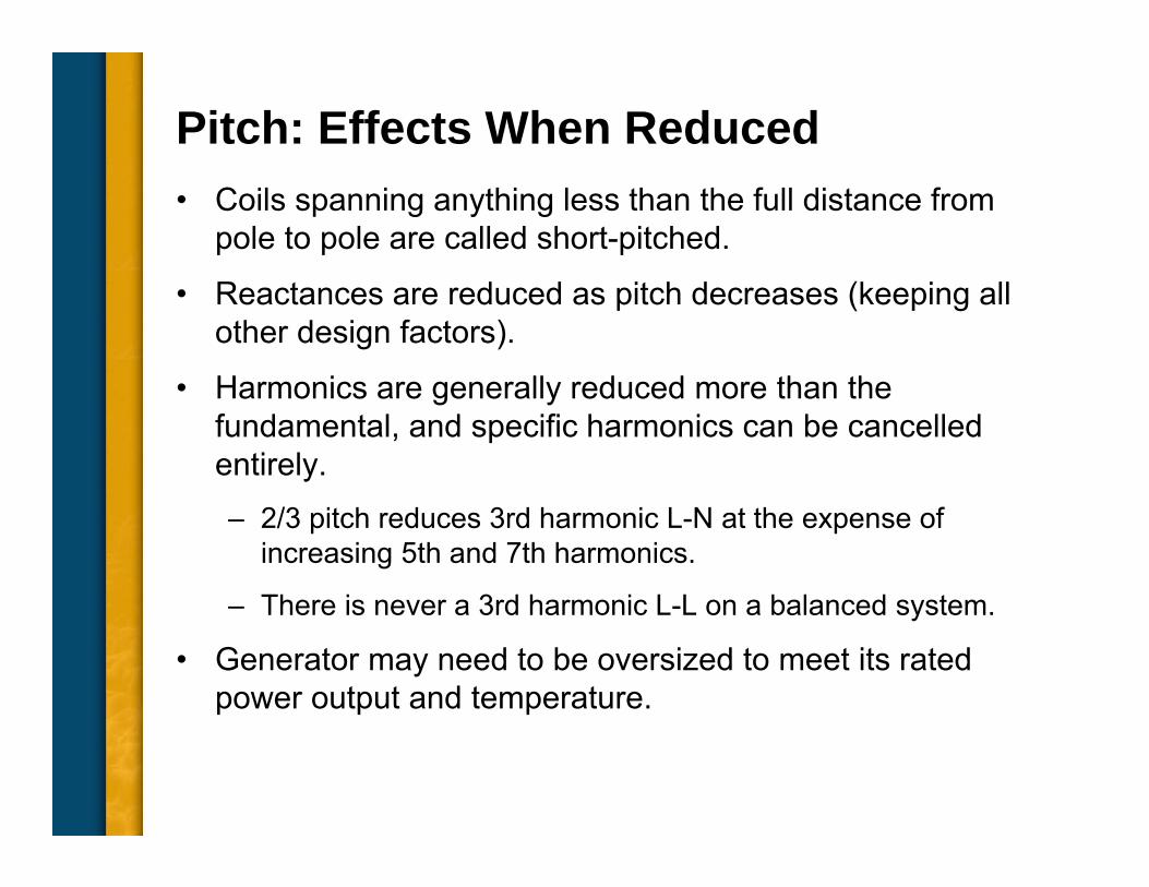
Pitch: Effects When Reduced• Coils spanning anything less than the full distance from
pole to pole are called short-pitched.
• Reactances are reduced as pitch decreases (keeping all other design factors).
• Harmonics are generally reduced more than the fundamental, and specific harmonics can be cancelled entirely.– 2/3 pitch reduces 3rd harmonic L-N at the expense of
increasing 5th and 7th harmonics.
– There is never a 3rd harmonic L-L on a balanced system.
• Generator may need to be oversized to meet its rated power output and temperature.
Common Topics, The Practical Side• Machine Output Voltage Equation
• Pitch
• Harmonics
• Circulating Currents when Paralleling
• Reactances and Time Constants
• Three Generator Curves Used for System Coordination – Thermal Damage Curve
– Decrement Curve
– Reactive Capability
• Efficiency
• Parallel Operation
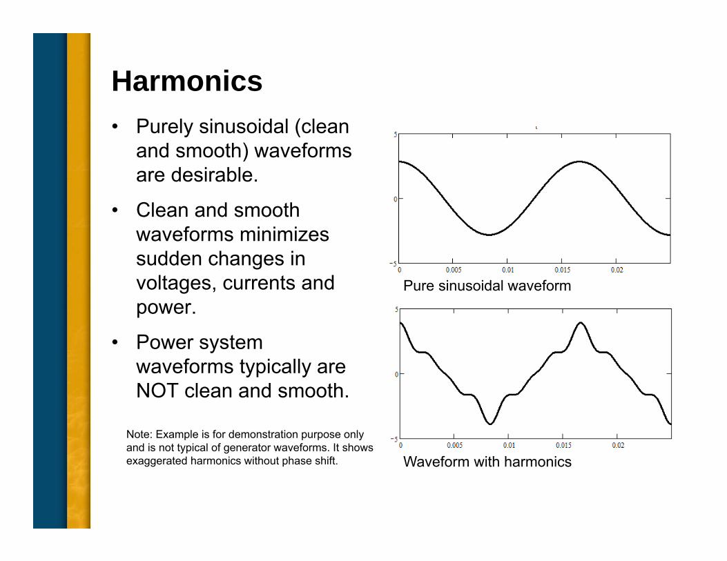
Harmonics• Purely sinusoidal (clean
and smooth) waveforms are desirable.
• Clean and smooth waveforms minimizes sudden changes in voltages, currents and power.
• Power system waveforms typically are NOT clean and smooth.
Pure sinusoidal waveform
Waveform with harmonics
Note: Example is for demonstration purpose only and is not typical of generator waveforms. It shows exaggerated harmonics without phase shift.
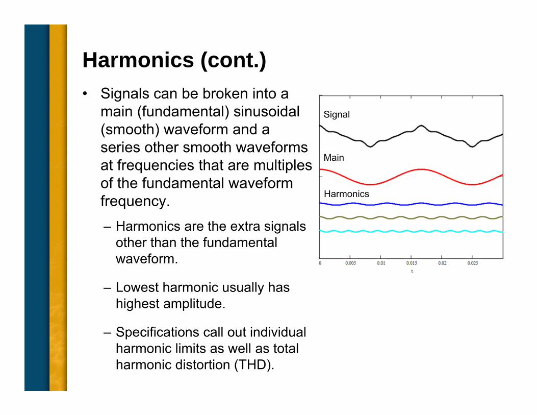
Signal
Main
Harmonics
Harmonics (cont.)• Signals can be broken into a
main (fundamental) sinusoidal (smooth) waveform and a series other smooth waveforms at frequencies that are multiples of the fundamental waveform frequency.– Harmonics are the extra signals
other than the fundamental waveform.
– Lowest harmonic usually has highest amplitude.
– Specifications call out individual harmonic limits as well as total harmonic distortion (THD).
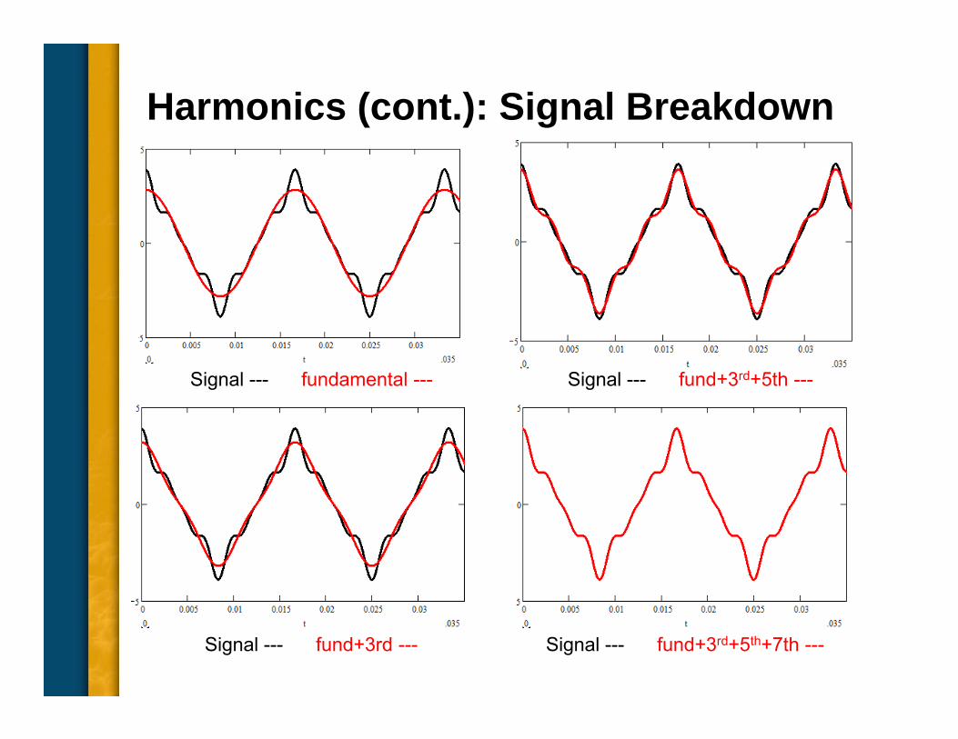
Harmonics (cont.): Signal Breakdown
Signal --- fundamental --- Signal --- fund+3rd+5th ---
Signal --- fund+3rd --- Signal --- fund+3rd+5th+7th ---
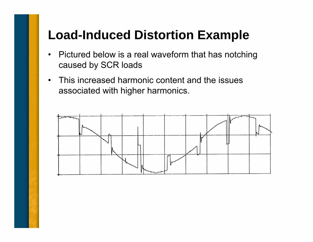
Load-Induced Distortion Example• Pictured below is a real waveform that has notching
caused by SCR loads
• This increased harmonic content and the issues associated with higher harmonics.
Harmonics (cont.): Resultant Problems• Insulation systems may stress and get damaged.
• Generator components may overheat, requiring derating of the generator.
• Motors on the system may experience overheating, high audible noise or increased torque ripple.
• Transformers may overheat due to harmonic flux core losses.
• Power factor correction capacitors and other electronic equipment may receive excess currents and/or voltages.
• Telephone systems may get interfered with by higher order harmonics - telephone-influence factor (TIF).
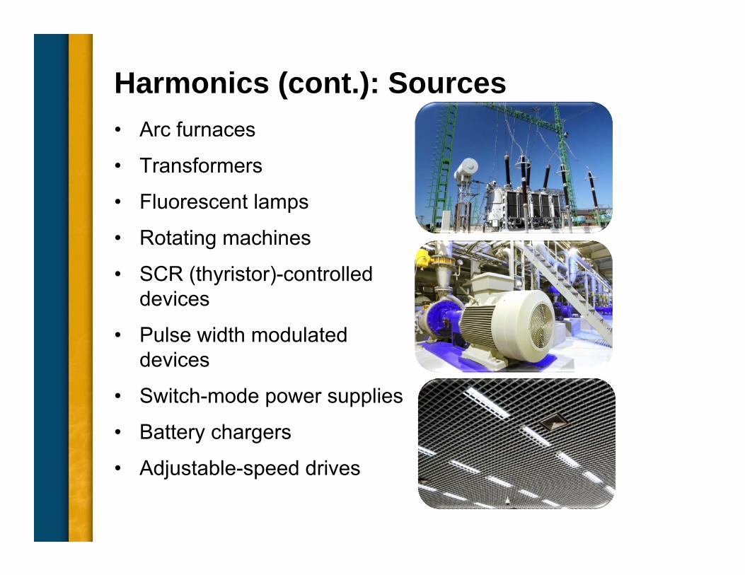
Harmonics (cont.): Sources• Arc furnaces
• Transformers
• Fluorescent lamps
• Rotating machines
• SCR (thyristor)-controlled devices
• Pulse width modulated devices
• Switch-mode power supplies
• Battery chargers
• Adjustable-speed drives
Common Topics, The Practical Side• Machine Output Voltage Equation
• Pitch
• Harmonics
• Circulating Currents when Paralleling
• Reactances and Time Constants
• Three Generator Curves Used for System Coordination – Thermal Damage Curve
– Decrement Curve
– Reactive Capability
• Efficiency
• Parallel Operation
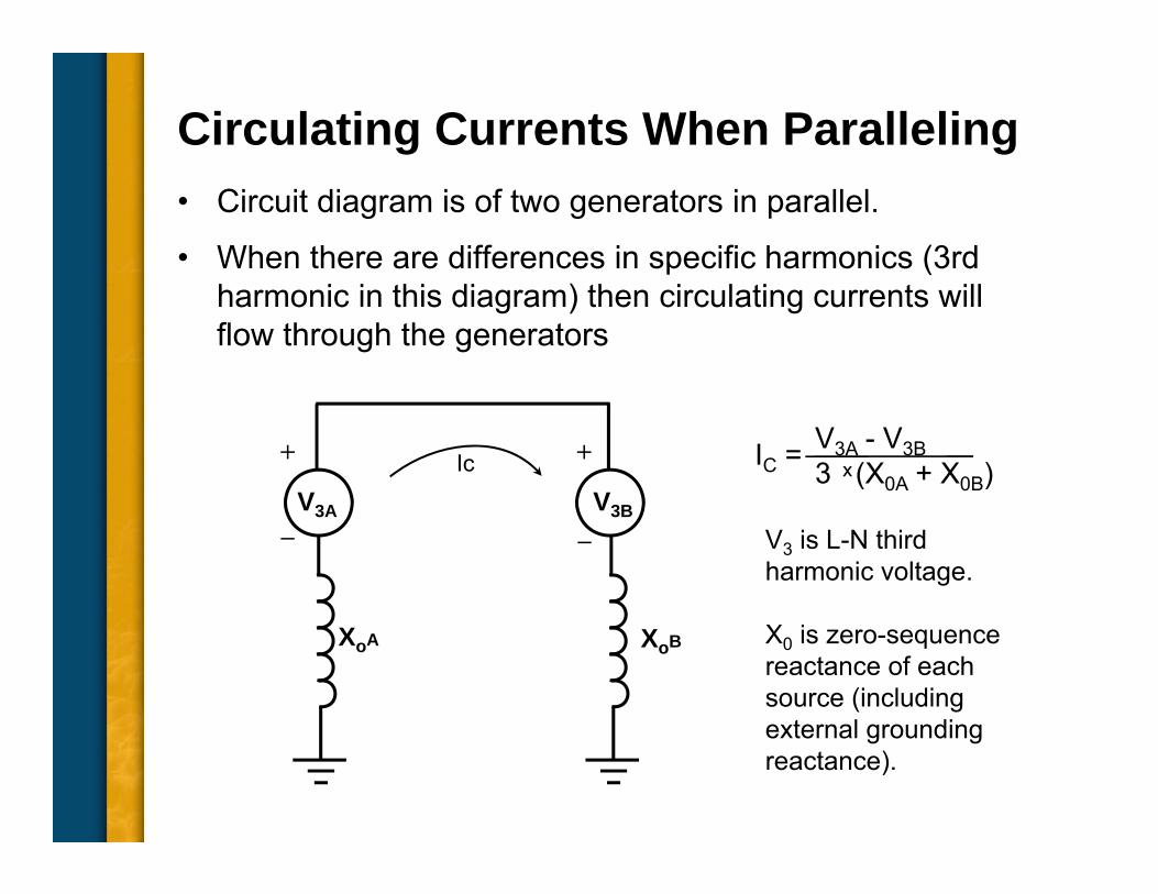
Circulating Currents When Paralleling• Circuit diagram is of two generators in parallel.
• When there are differences in specific harmonics (3rd harmonic in this diagram) then circulating currents will flow through the generators
IC = V3A - V3B3 ͯ (X0A + X0B)
V3 is L-N third harmonic voltage.
X0 is zero-sequence reactance of each source (including external grounding reactance).
XoB
Ic
XoA
V3A V3B
+ +
_ _
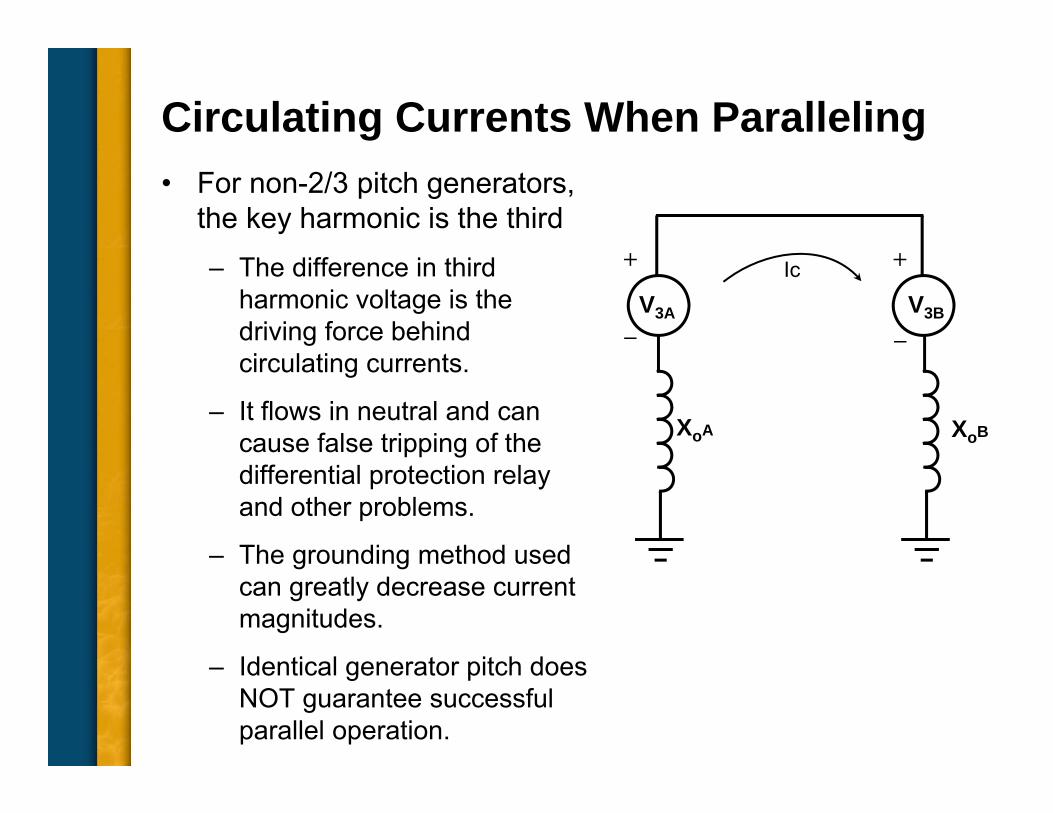
Circulating Currents When Paralleling• For non-2/3 pitch generators,
the key harmonic is the third– The difference in third
harmonic voltage is the driving force behind circulating currents.
– It flows in neutral and can cause false tripping of the differential protection relay and other problems.
– The grounding method used can greatly decrease current magnitudes.
– Identical generator pitch does NOT guarantee successful parallel operation.
XoB
Ic
XoA
V3A V3B
+ +
_ _
Common Topics, The Practical Side• Machine Output Voltage Equation
• Pitch
• Harmonics
• Circulating Currents when Paralleling
• Reactances and Time Constants
• Three Generator Curves Used for System Coordination – Thermal Damage Curve
– Decrement Curve
– Reactive Capability
• Efficiency
• Parallel Operation
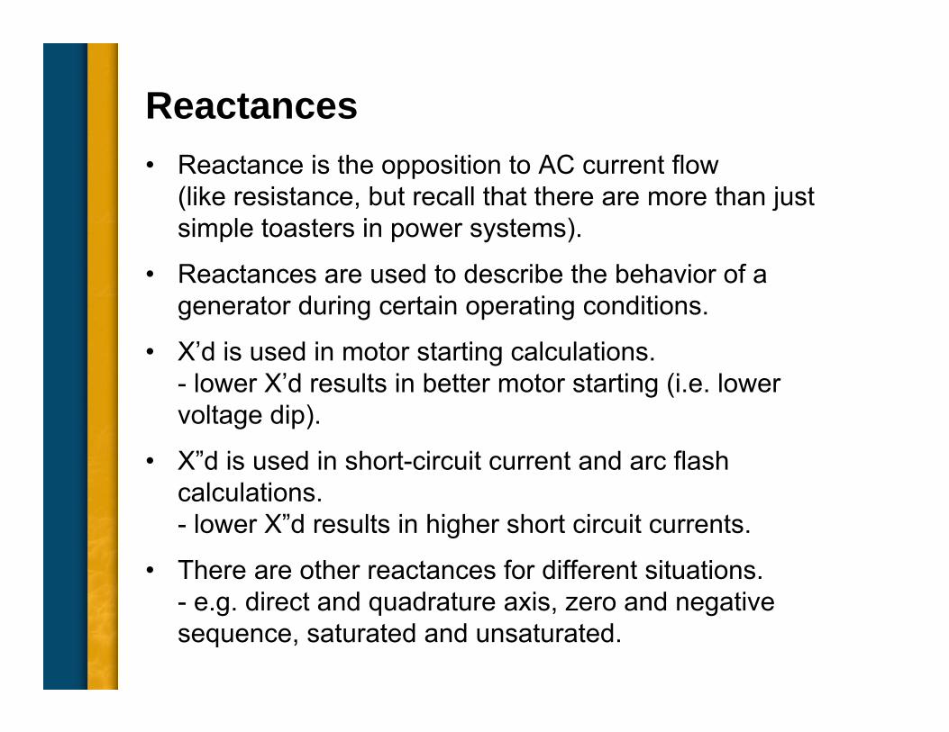
Reactances• Reactance is the opposition to AC current flow
(like resistance, but recall that there are more than just simple toasters in power systems).
• Reactances are used to describe the behavior of a generator during certain operating conditions.
• X’d is used in motor starting calculations.- lower X’d results in better motor starting (i.e. lower voltage dip).
• X”d is used in short-circuit current and arc flash calculations.- lower X”d results in higher short circuit currents.
• There are other reactances for different situations.- e.g. direct and quadrature axis, zero and negative sequence, saturated and unsaturated.
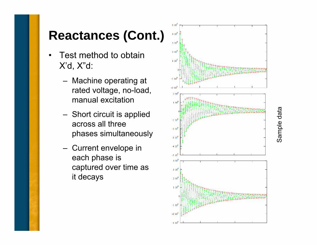
Reactances (Cont.)• Test method to obtain
X’d, X”d:– Machine operating at
rated voltage, no-load, manual excitation
– Short circuit is applied across all three phases simultaneously
– Current envelope in each phase is captured over time as it decays
Sam
ple
data
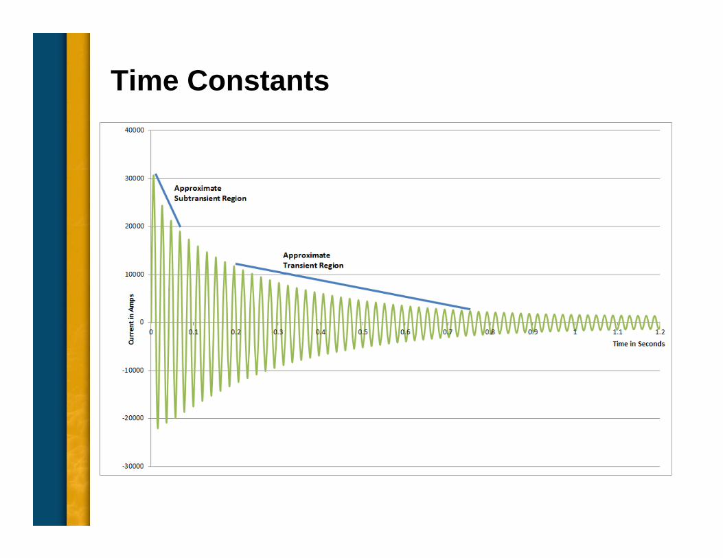
Time Constants• Time constants characterize the length of time that
currents flow during a specific instant in time of a given configuration.
• The two most common are the subtransient time constant T”d and the transient time constant T’.– Sub-transient time constant T”d determines length of time
sub-transient (damper) current flows.
– Transient time constant T’d determines length of time transient current flows.
Time Constants
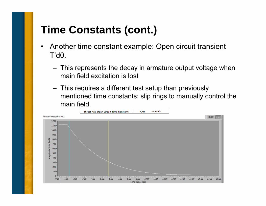
Time Constants (cont.)• Another time constant example: Open circuit transient
T’d0.– This represents the decay in armature output voltage when
main field excitation is lost
– This requires a different test setup than previously mentioned time constants: slip rings to manually control the main field.
Reactances, Time Constants: Why are they Important?• Very useful to predict performance in large system
simulations because they simplify and speed up calculations.
• Now, for many users, the reactances and time constants are plugged into simulators used for system modeling and coordination studies.
• Generator manufacturers use this information to produce three curves commonly used for system coordination:– Thermal damage curve
– Short-circuit decrement curve
– Reactive Capability
Common Topics, The Practical Side• Machine Output Voltage Equation
• Pitch
• Harmonics
• Circulating Currents when Paralleling
• Reactances and Time Constants
• Two Generator Curves Used for System Coordination – Thermal Damage Curve
– Decrement Curve
– Reactive Capability
• Efficiency
• Parallel Operation
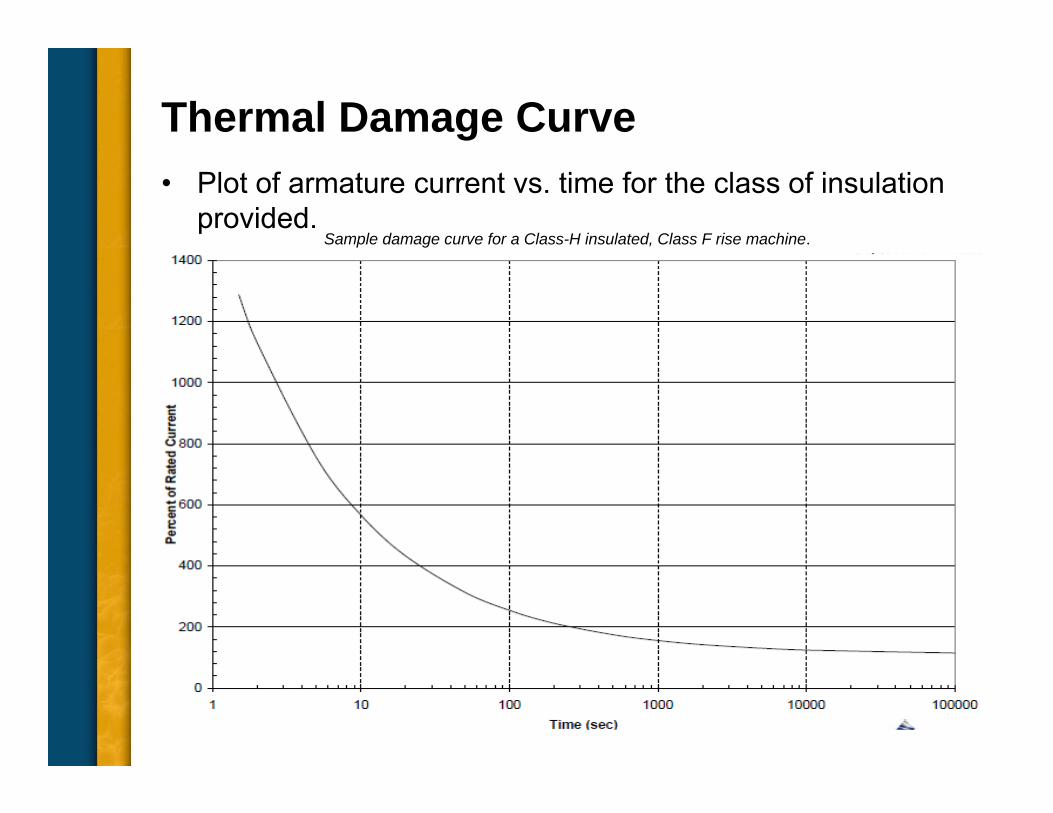
Thermal Damage Curve• Plot of armature current vs. time for the class of insulation
provided.Sample damage curve for a Class-H insulated, Class F rise machine.
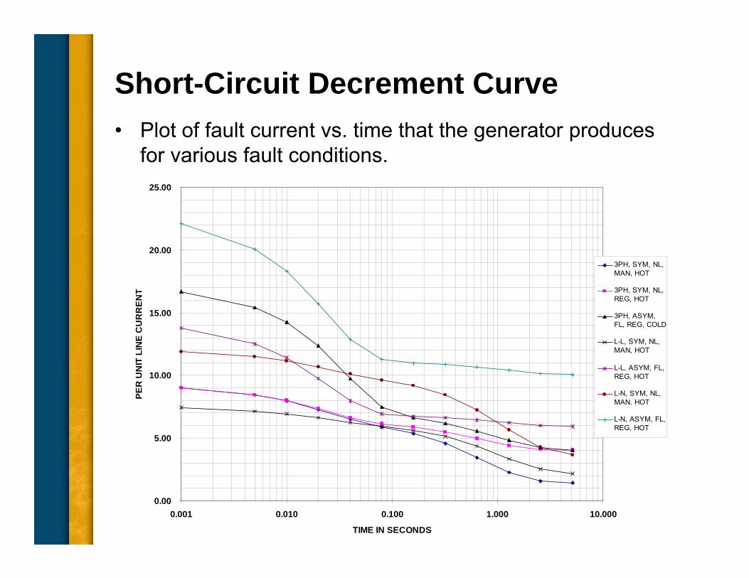
Short-Circuit Decrement Curve• Plot of fault current vs. time that the generator produces
for various fault conditions.
0.00
5.00
10.00
15.00
20.00
25.00
0.001 0.010 0.100 1.000 10.000
TIME IN SECONDS
PER
UN
IT L
INE
CU
RR
ENT
3PH, SYM, NL,MAN, HOT
3PH, SYM, NL,REG, HOT
3PH, ASYM,FL, REG, COLD
L-L, SYM, NL,MAN, HOT
L-L, ASYM, FL,REG, HOT
L-N, SYM, NL,MAN. HOT
L-N, ASYM, FL,REG, HOT
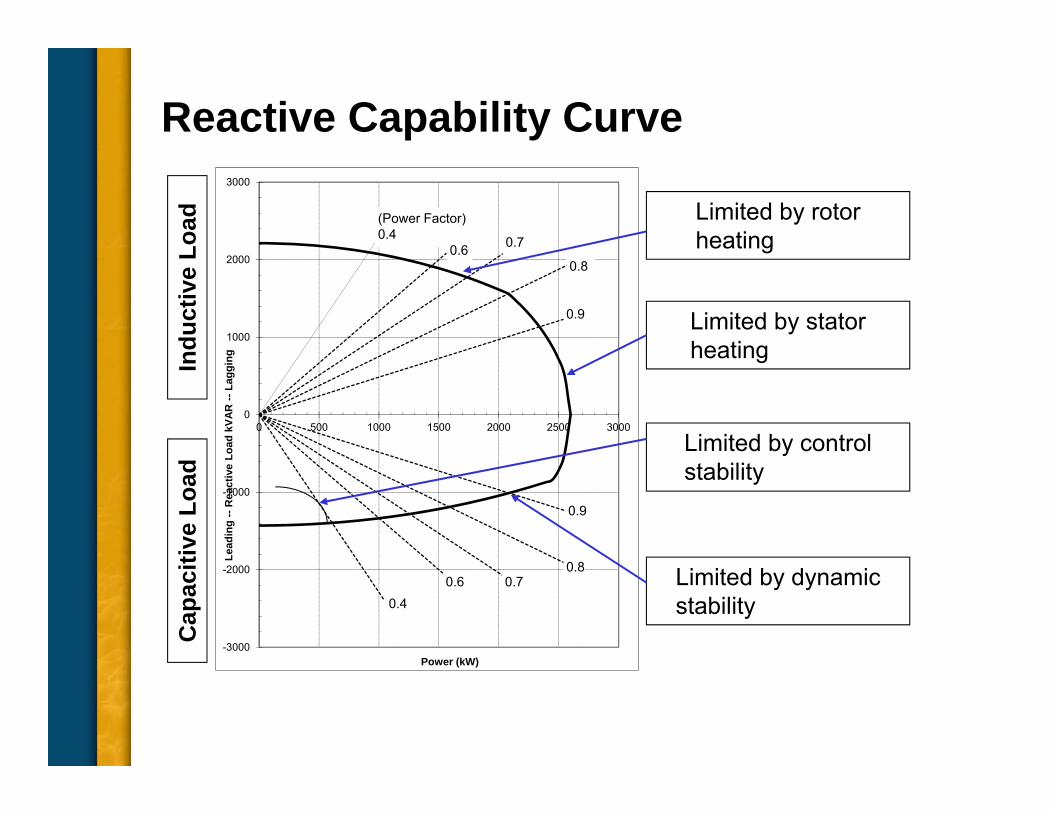
Reactive Capability Curve
Limited by rotor heating
Limited by dynamic stability
Limited by control stability
Indu
ctiv
e Lo
adC
apac
itive
Loa
d
-3000
-2000
-1000
0
1000
2000
3000
0 500 1000 1500 2000 2500 3000
Lead
ing
--R
eact
ive
Load
kVA
R --
Lagg
ing
Power (kW)
(Power Factor)0.4
0.6 0.7
0.8
0.9
0.9
0.80.7
0.40.6
Limited by stator heating
Common Topics, The Practical Side• Machine Output Voltage Equation
• Pitch
• Harmonics
• Circulating Currents when Paralleling
• Reactances and Time Constants
• Three Generator Curves Used for System Coordination – Thermal Damage Curve
– Decrement Curve
– Reactive Capability
• Efficiency
• Parallel Operation
Efficiency• Ratio of electrical energy output against the required
mechanical energy input.
• Usually expressed as a percentage and always less than 100 percent.
• Usually improves with increasing sizes. – For a 5 kW output, a typical efficiency is about 80%.
– For a 500 kW output, efficiency is typically 93% or better.
• Reduced by losses:– Fixed losses (independent of load current)
– Variable losses (directly proportional to load current)
Efficiency: Fixed Losses• Fixed losses
– Friction and windage losses:
• Bearing friction and wind resistance spinning rotor and associated fans
• Reduce by optimizing fan blade pitch
– Laminated core losses:
• Hysteresis
– Heat losses in the stator core due to change in magnetic flux flow
– Reduce by using low-loss silicon steel
• Eddy-current losses
– Loses due to induced current in the stator core
– Reduce by using low-loss silicon steel
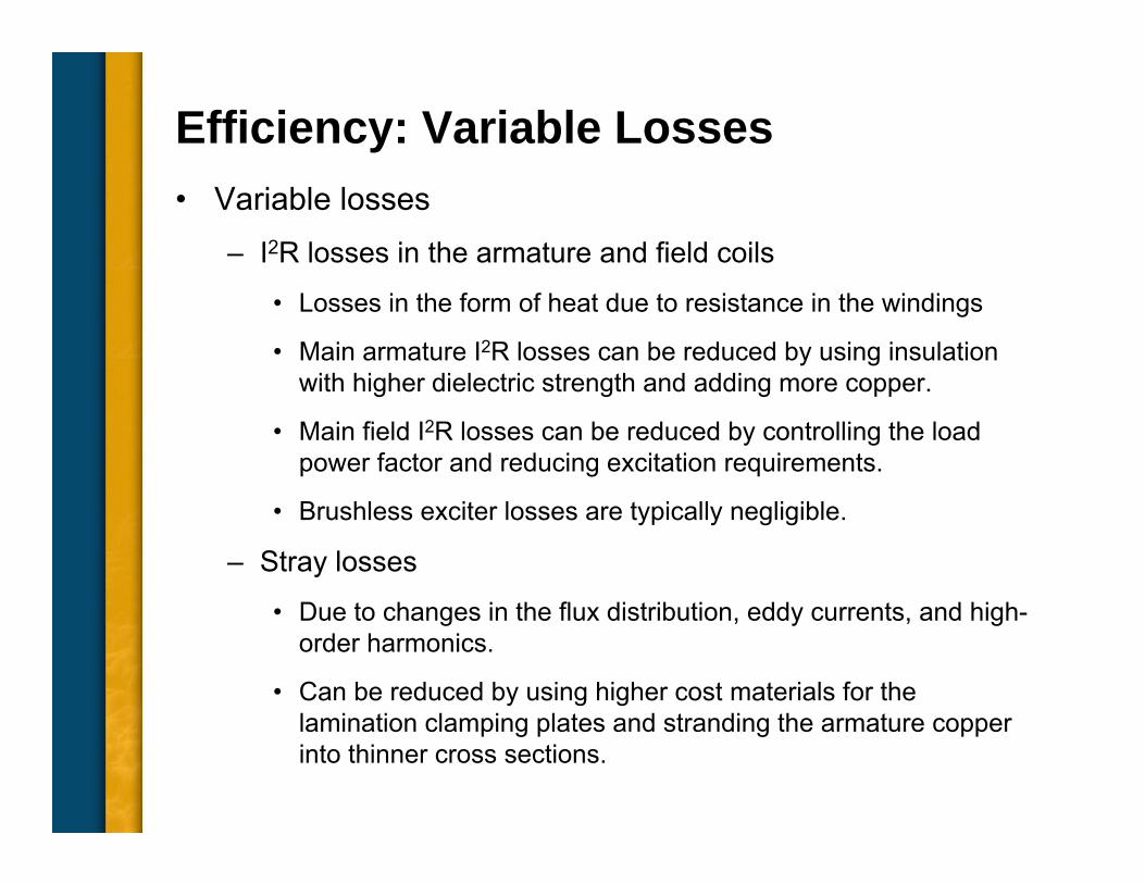
Efficiency: Variable Losses• Variable losses
– I2R losses in the armature and field coils
• Losses in the form of heat due to resistance in the windings
• Main armature I2R losses can be reduced by using insulation with higher dielectric strength and adding more copper.
• Main field I2R losses can be reduced by controlling the load power factor and reducing excitation requirements.
• Brushless exciter losses are typically negligible.
– Stray losses
• Due to changes in the flux distribution, eddy currents, and high-order harmonics.
• Can be reduced by using higher cost materials for the lamination clamping plates and stranding the armature copper into thinner cross sections.
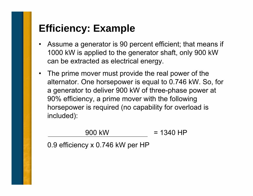
Efficiency: Example• Assume a generator is 90 percent efficient; that means if
1000 kW is applied to the generator shaft, only 900 kW can be extracted as electrical energy.
• The prime mover must provide the real power of the alternator. One horsepower is equal to 0.746 kW. So, for a generator to deliver 900 kW of three-phase power at 90% efficiency, a prime mover with the following horsepower is required (no capability for overload is included):
900 kW = 1340 HP
0.9 efficiency x 0.746 kW per HP
Common Topics, The Practical Side• Machine Output Voltage Equation
• Pitch
• Harmonics
• Circulating Currents when Paralleling
• Reactances and Time Constants
• Three Generator Curves Used for System Coordination – Thermal Damage Curve
– Decrement Curve
– Reactive Capability
• Efficiency
• Parallel Operation
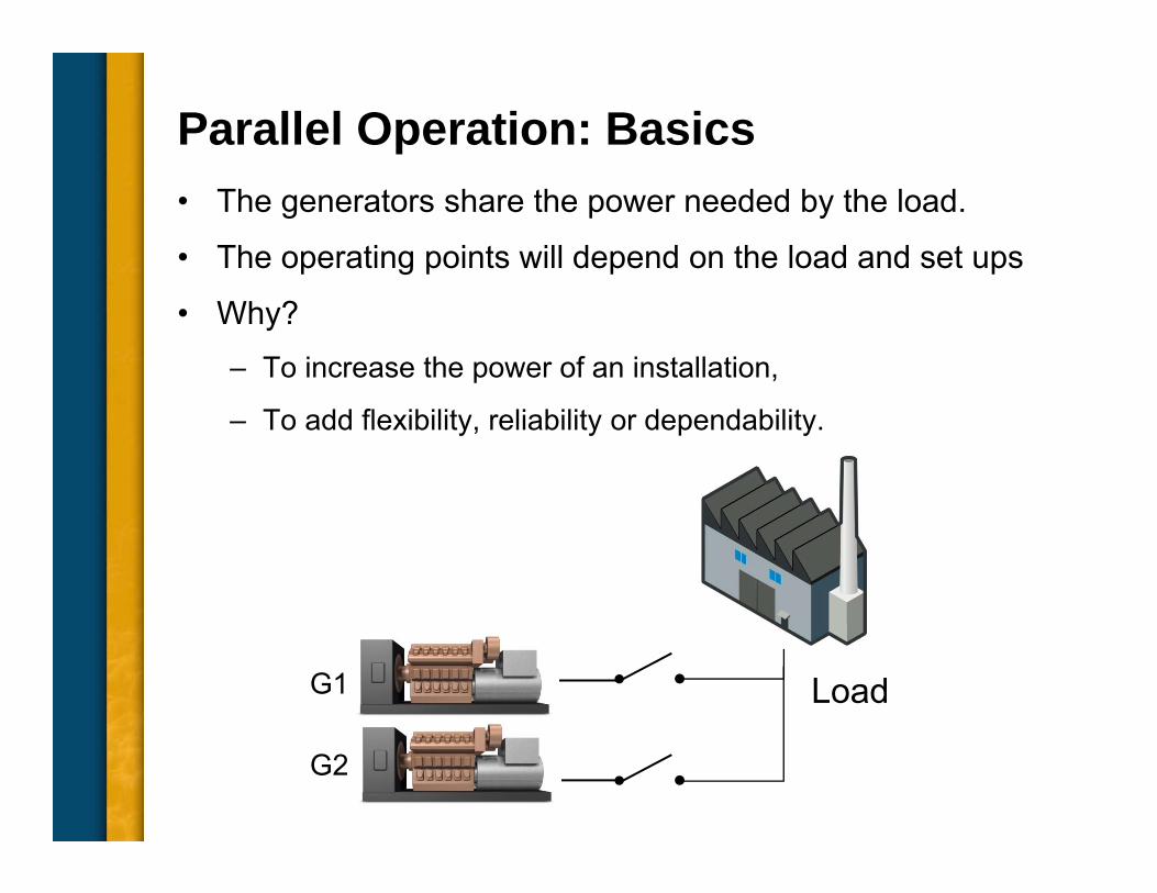
Parallel Operation: Basics• The generators share the power needed by the load.
• The operating points will depend on the load and set ups
• Why?– To increase the power of an installation,
– To add flexibility, reliability or dependability.
LoadG1
G2
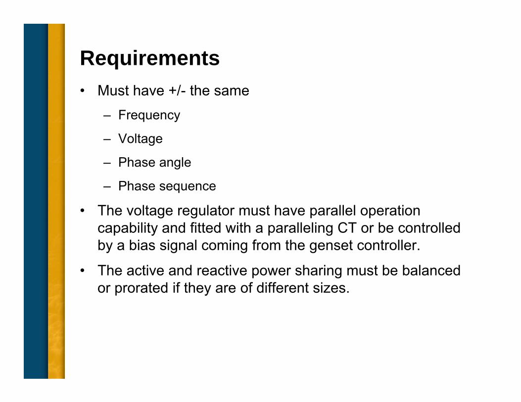
Requirements• Must have +/- the same
– Frequency
– Voltage
– Phase angle
– Phase sequence
• The voltage regulator must have parallel operation capability and fitted with a paralleling CT or be controlled by a bias signal coming from the genset controller.
• The active and reactive power sharing must be balanced or prorated if they are of different sizes.
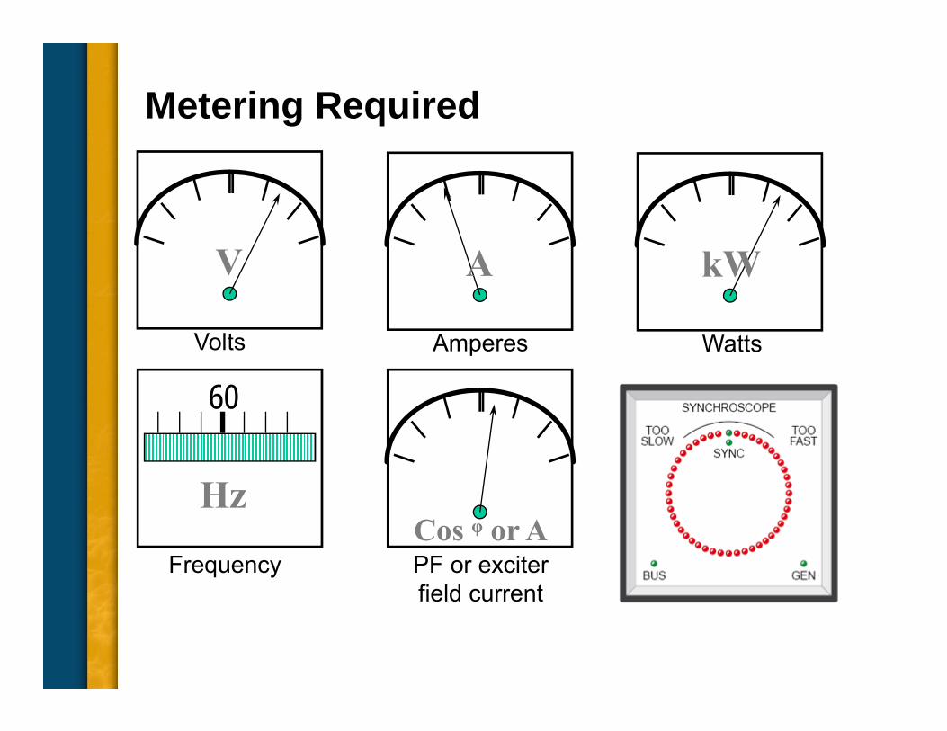
Metering Required
V
Volts
A
Amperes
kW
Watts
60
FrequencyCos ᵠ or APF or exciter field current
Hz
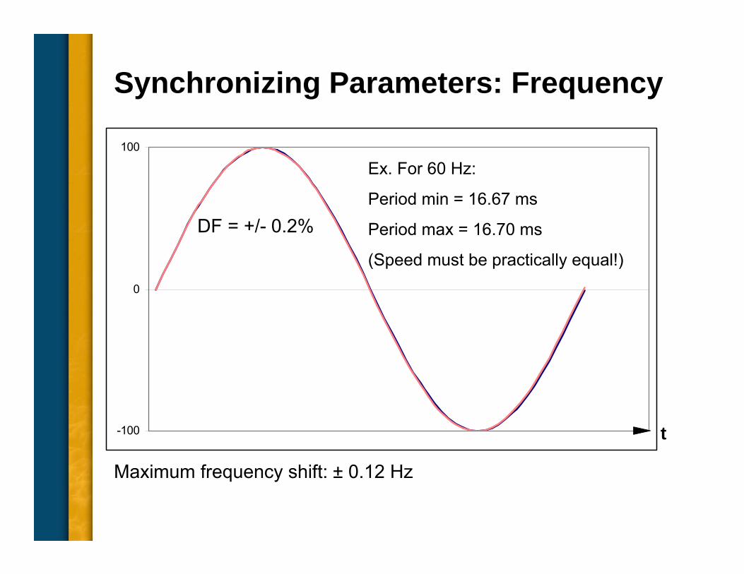
Synchronizing Parameters: Frequency
-100
0
100
Ex. For 60 Hz:
Period min = 16.67 ms
Period max = 16.70 ms
(Speed must be practically equal!)
Maximum frequency shift: ± 0.12 Hz
DF = +/- 0.2%
t
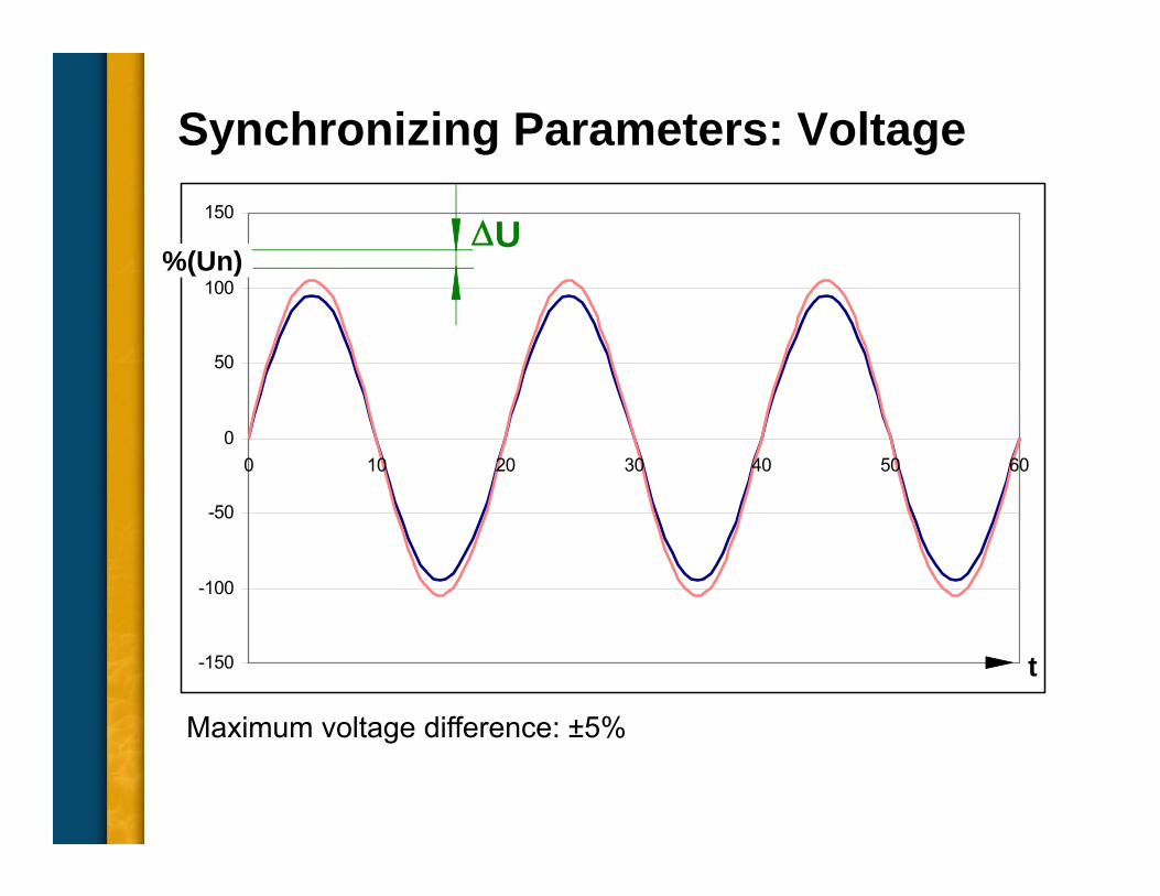
Synchronizing Parameters: Voltage
-150
-100
-50
0
50
100
150
0 10 20 30 40 50 60
%(Un)U
Maximum voltage difference: ±5%
t
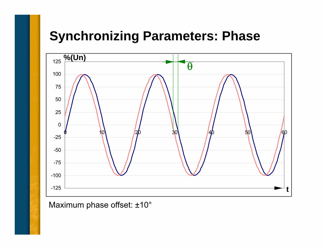
Synchronizing Parameters: Phase
-125
-100
-75
-50
-25
0
25
50
75
100
125
0 10 20 30 40 50 60
t
%(Un)
Maximum phase offset: ±10°
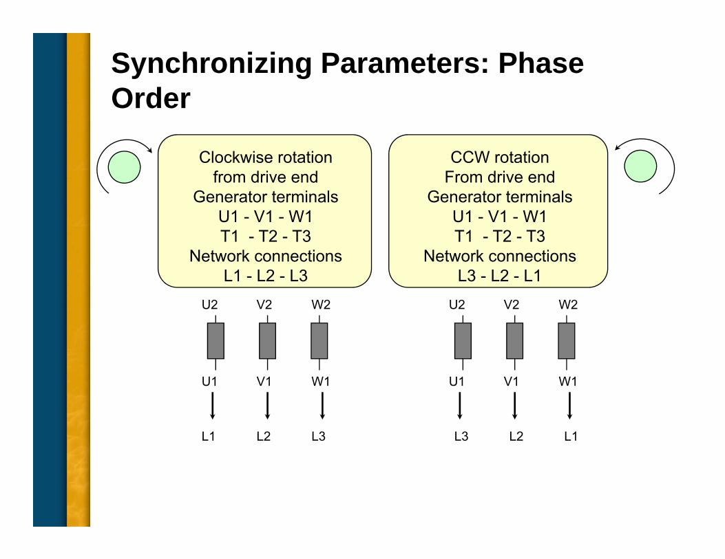
Synchronizing Parameters: Phase Order
Clockwise rotationfrom drive end
Generator terminalsU1 - V1 - W1T1 - T2 - T3
Network connectionsL1 - L2 - L3
U2 V2 W2
L1 L2 L3
U1 V1 W1
CCW rotationFrom drive end
Generator terminalsU1 - V1 - W1T1 - T2 - T3
Network connectionsL3 - L2 - L1
U2 V2 W2
U1 V1 W1
L3 L2 L1
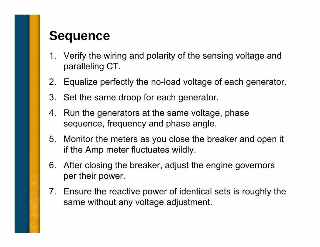
Sequence1. Verify the wiring and polarity of the sensing voltage and
paralleling CT.
2. Equalize perfectly the no-load voltage of each generator.
3. Set the same droop for each generator.
4. Run the generators at the same voltage, phase sequence, frequency and phase angle.
5. Monitor the meters as you close the breaker and open it if the Amp meter fluctuates wildly.
6. After closing the breaker, adjust the engine governors per their power.
7. Ensure the reactive power of identical sets is roughly the same without any voltage adjustment.
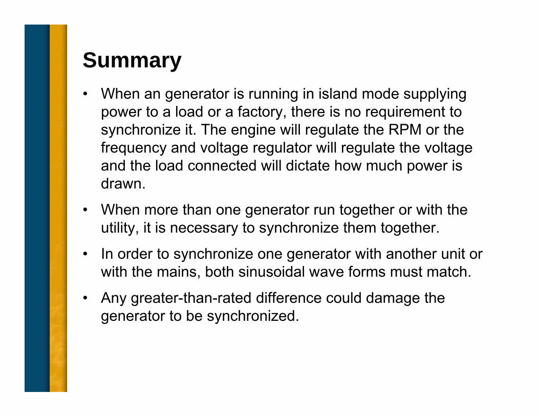
Summary• When an generator is running in island mode supplying
power to a load or a factory, there is no requirement to synchronize it. The engine will regulate the RPM or the frequency and voltage regulator will regulate the voltage and the load connected will dictate how much power is drawn.
• When more than one generator run together or with the utility, it is necessary to synchronize them together.
• In order to synchronize one generator with another unit or with the mains, both sinusoidal wave forms must match.
• Any greater-than-rated difference could damage the generator to be synchronized.


![BPMN Advanced Concepts[1]](https://img.pdfslide.us/doc/110x75/577cc3651a28aba71195ee74/bpmn-advanced-concepts1.jpg)