Embed Size (px)
DESCRIPTION
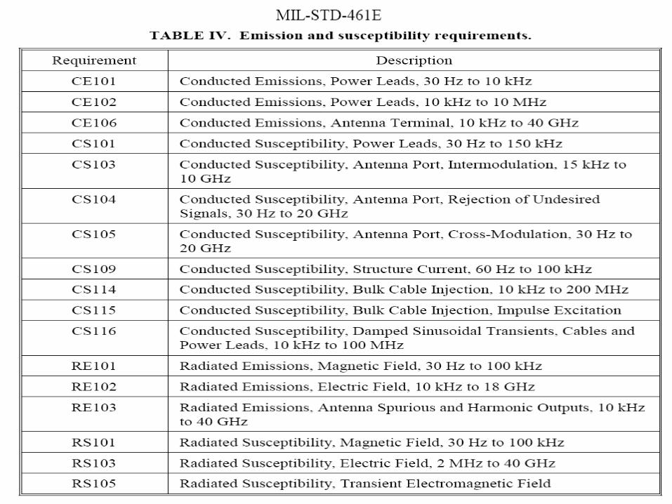
MIL STD 461
Citation preview

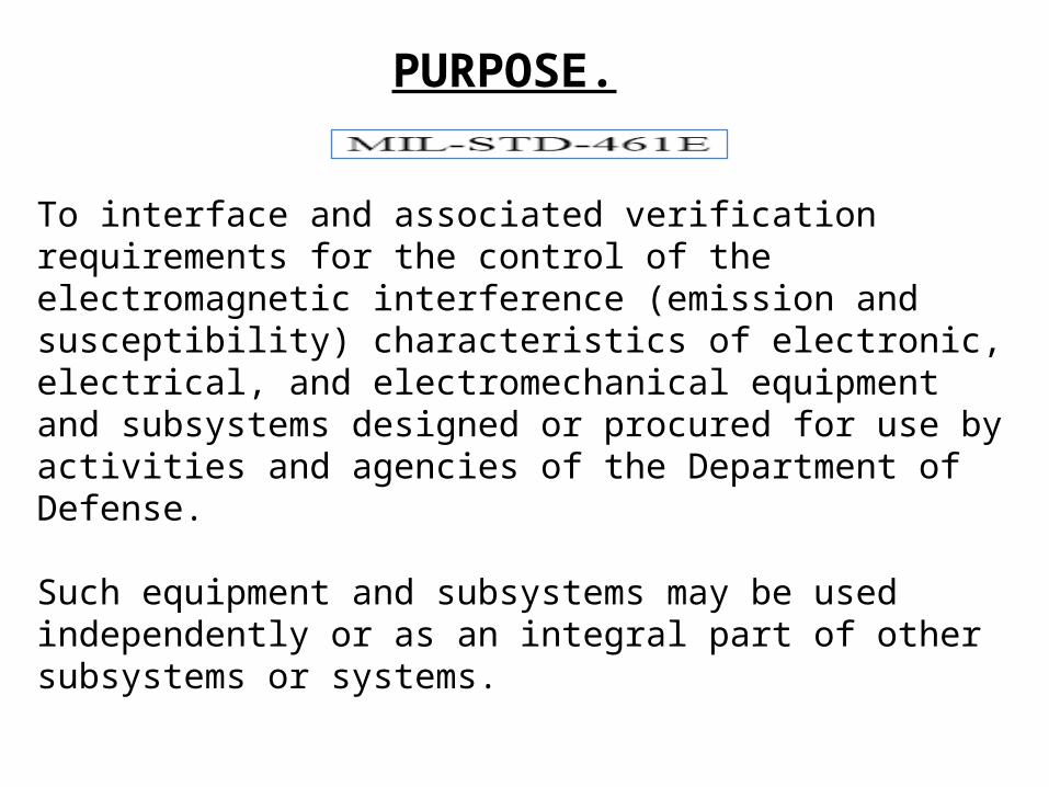
To interface and associated verification requirements for the control of the electromagnetic interference (emission and susceptibility) characteristics of electronic, electrical, and electromechanical equipment and subsystems designed or procured for use by activities and agencies of the Department of Defense.
Such equipment and subsystems may be used independently or as an integral part of other subsystems or systems.
PURPOSE.

STRATEGY OF EMC RISK
UK Defence Standardization
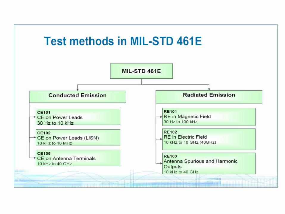
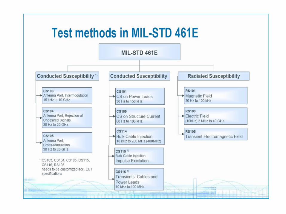
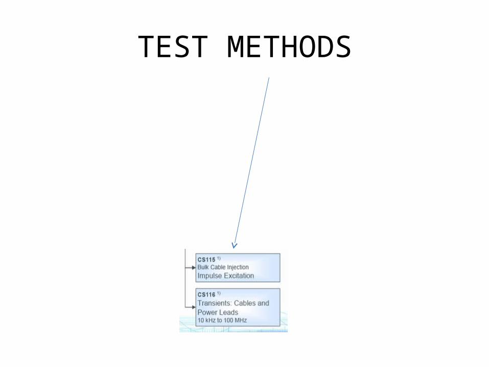
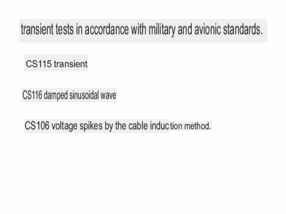
TEST METHODS
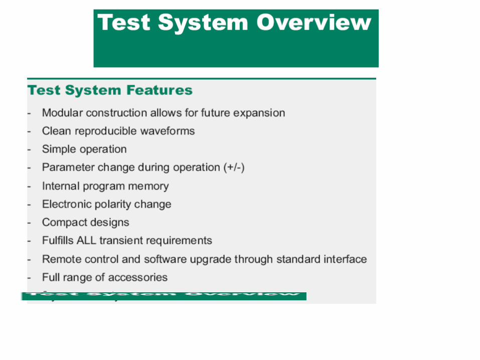
Military Test System
for Transient
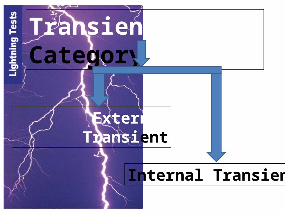
Transient Category
External Transient
Internal Transient
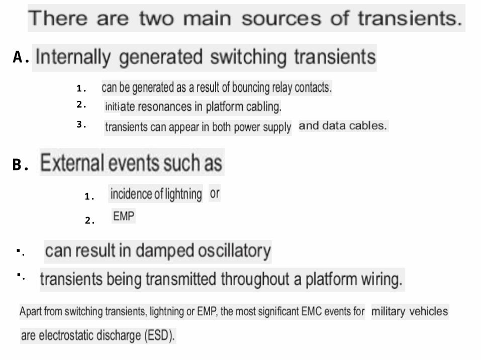
A.
B.
1.
2.
3.
1.
2.
.
.
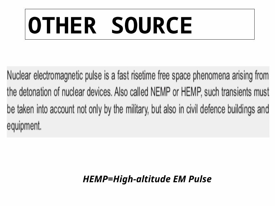
HEMP=High-altitude EM Pulse
OTHER SOURCE

NATURE
NATURE
IMPULSE EXCITATION
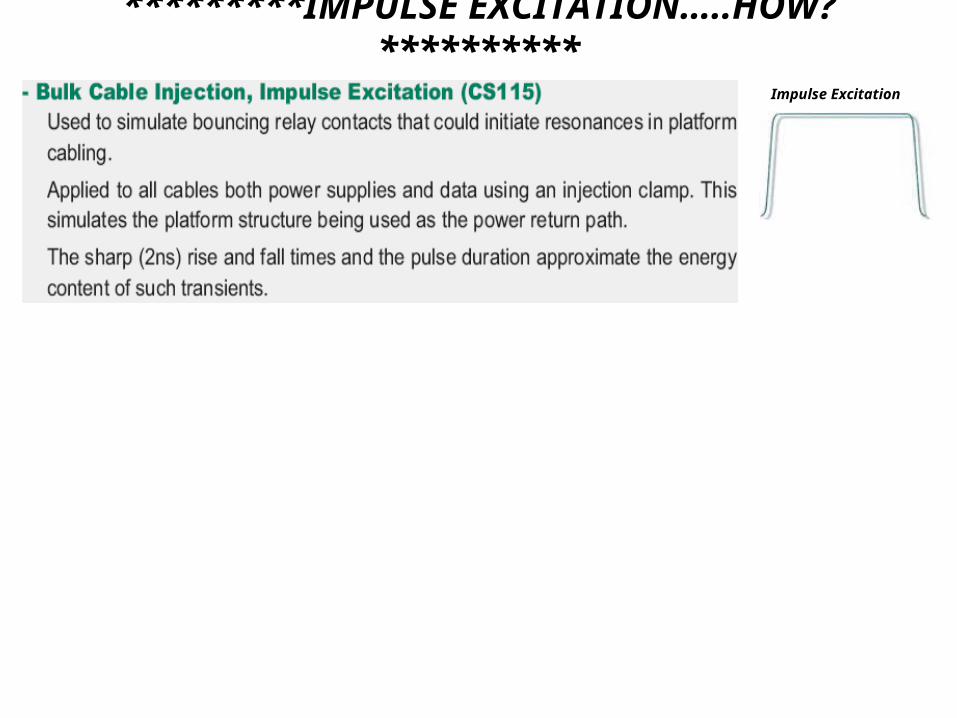
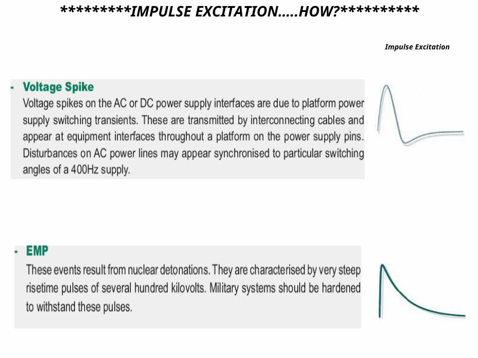
*********IMPULSE EXCITATION…..HOW?**********
Impulse Excitation
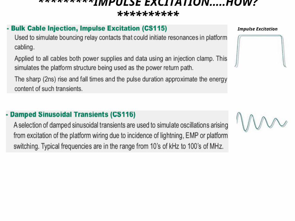
*********IMPULSE EXCITATION…..HOW?**********
Impulse Excitation
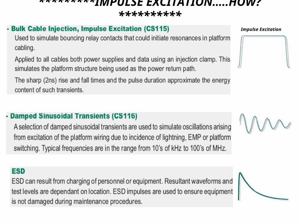
*********IMPULSE EXCITATION…..HOW?**********
Impulse Excitation
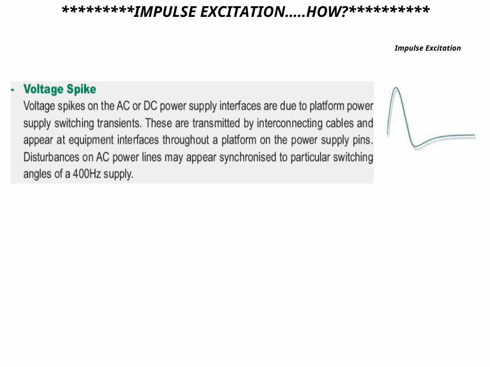
*********IMPULSE EXCITATION…..HOW?**********
Impulse Excitation
*********IMPULSE EXCITATION…..HOW?**********
Impulse Excitation
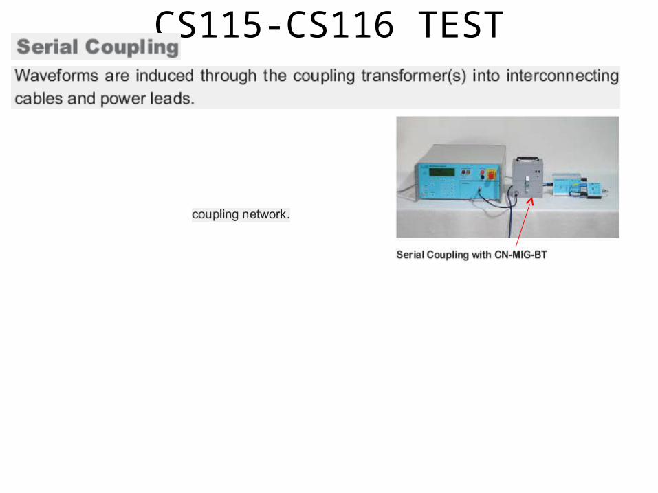
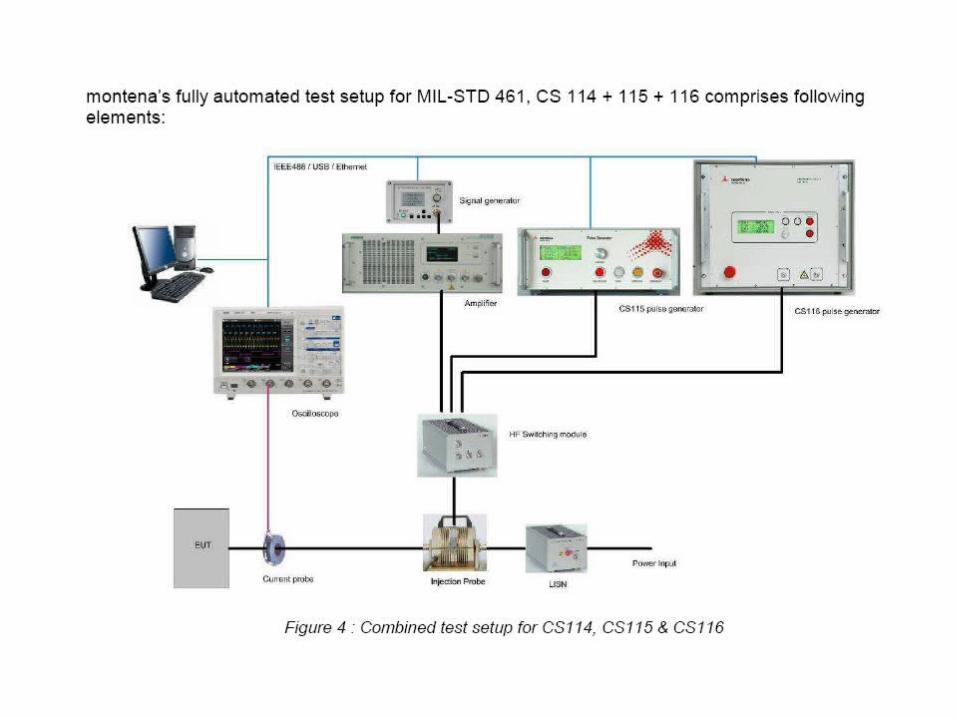
CS115-CS116 TEST
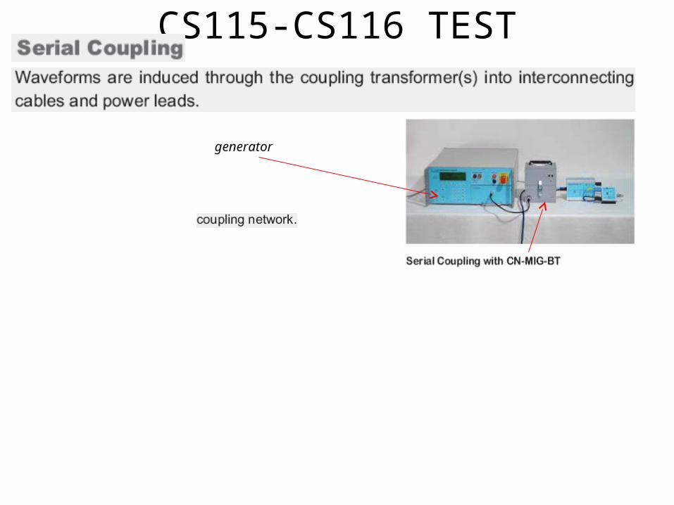
CS115-CS116 TEST
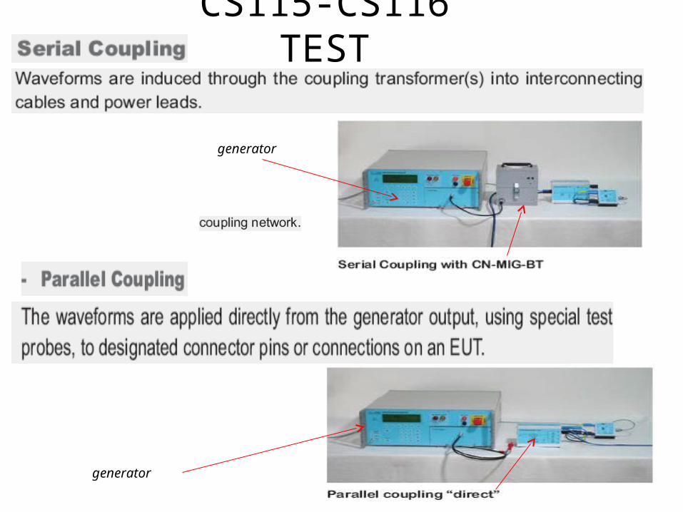
CS115-CS116 TEST
CS115-CS116 TEST
CS115-CS116 TEST
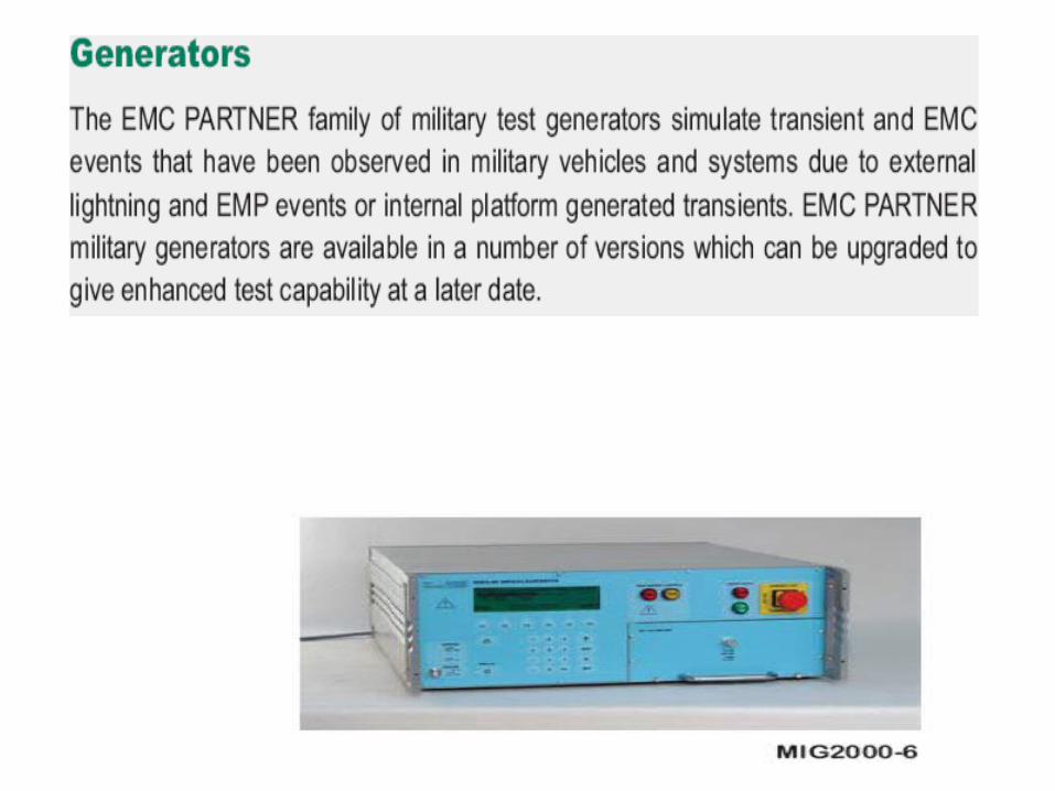
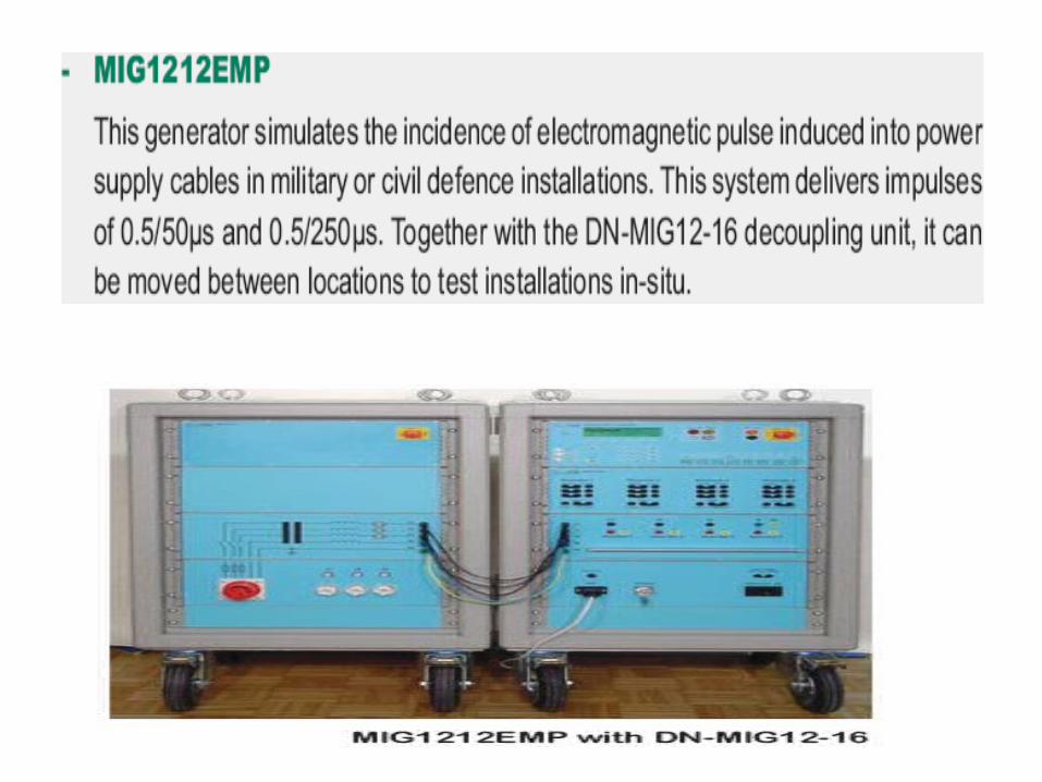
generator
CS115-CS116 TEST
generator
generator
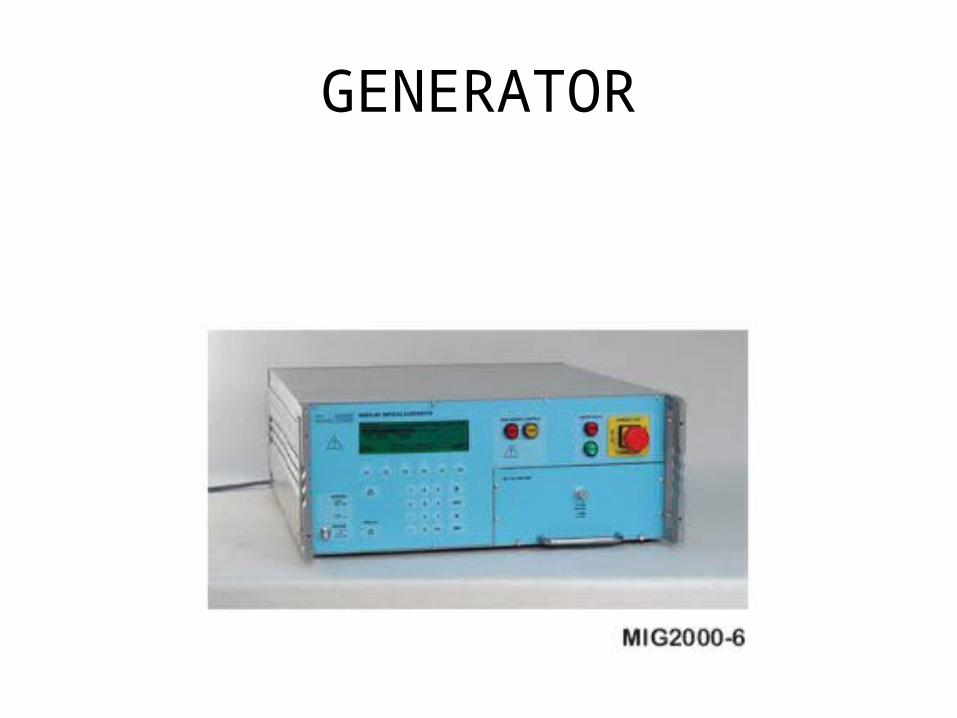
GENERATOR
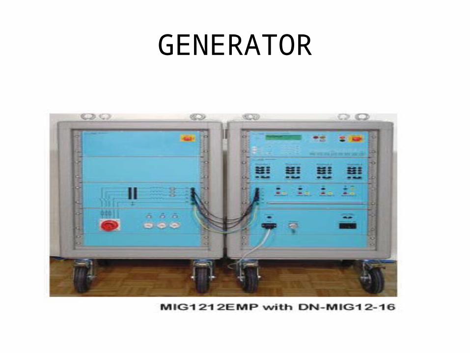
GENERATOR

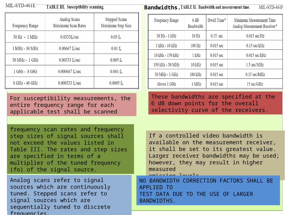
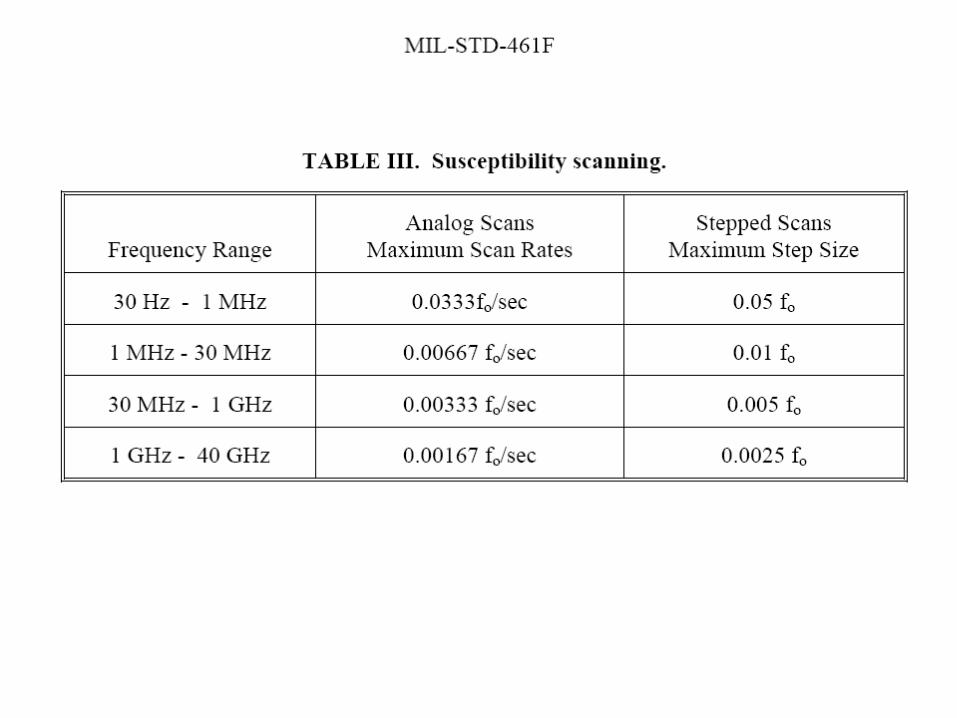
For susceptibility measurements, the entire frequency range for each applicable test shall be scanned
frequency scan rates and frequency step sizes of signal sources shall not exceed the values listed in Table III. The rates and step sizes are specified in terms of a multiplier of the tuned frequency (fo) of the signal source.
Analog scans refer to signal sources which are continuously tuned. Stepped scans refer to signal sources which are sequentially tuned to discrete frequencies.
If a controlled video bandwidth is available on the measurement receiver, it shall be set to its greatest value. Larger receiver bandwidths may be used; however, they may result in higher measuredemission levels.
These bandwidths are specified at the 6 dB down points for the overall selectivity curve of the receivers.
Bandwidths.
NO BANDWIDTH CORRECTION FACTORS SHALL BE APPLIED TOTEST DATA DUE TO THE USE OF LARGER BANDWIDTHS.
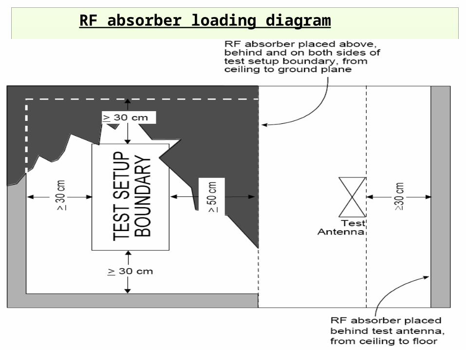
RF absorber loading diagram
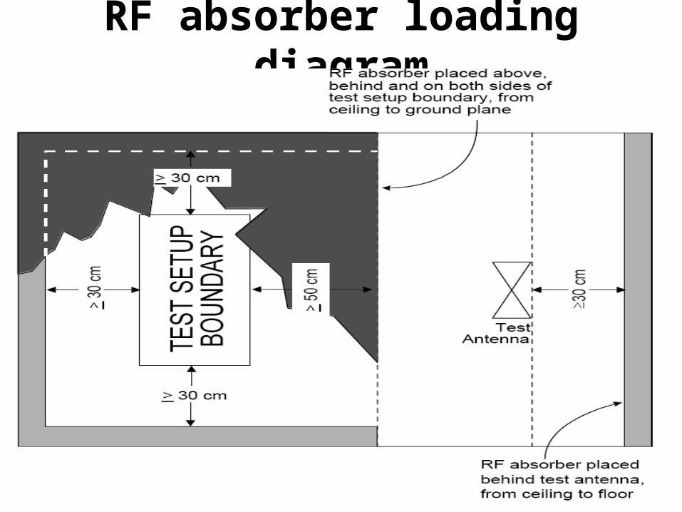
RF absorber loading diagram
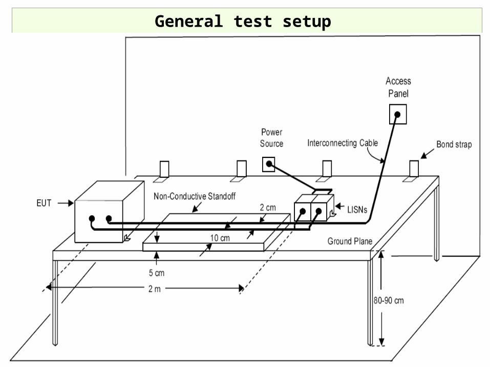
General test setup
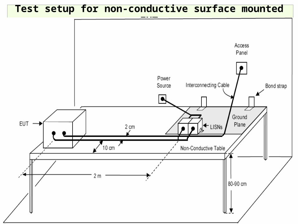
Test setup for non-conductive surface mounted EUT
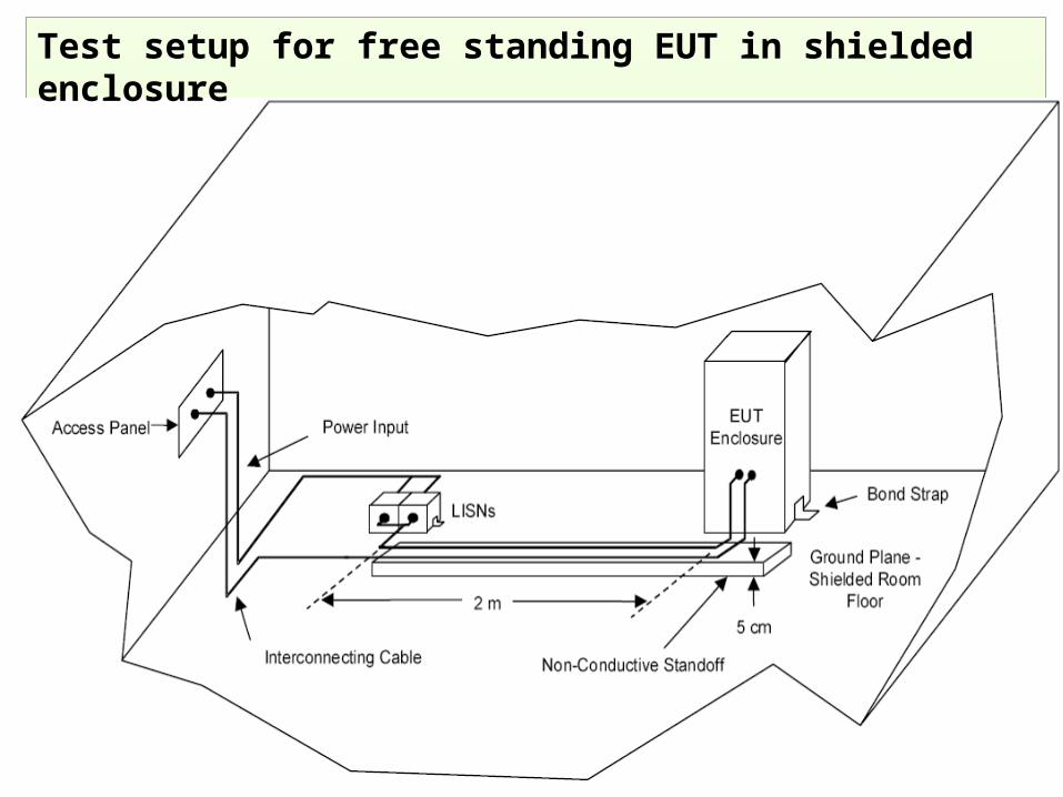
Test setup for free standing EUT in shielded enclosure
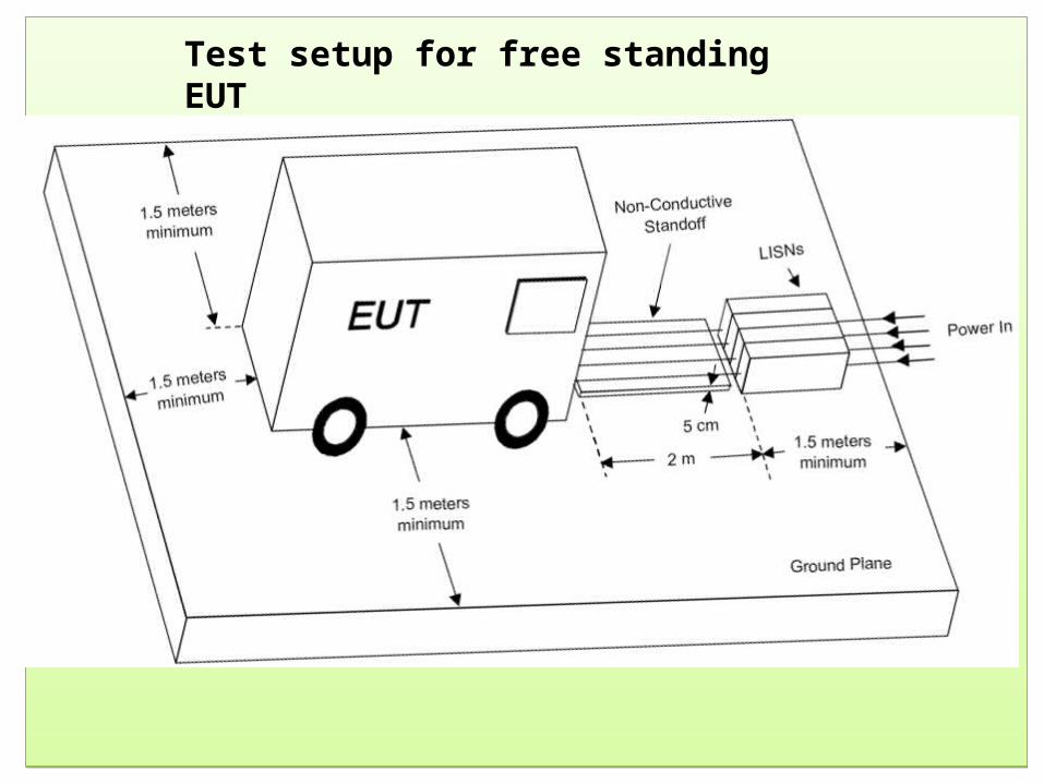
Test setup for free standing EUT
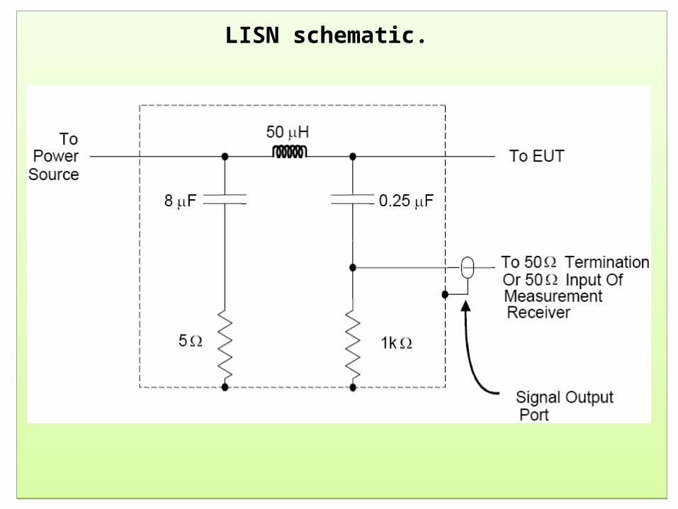
LISN schematic.
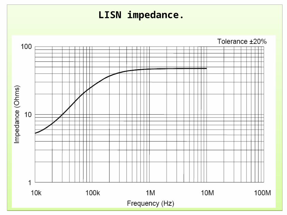
LISN impedance.
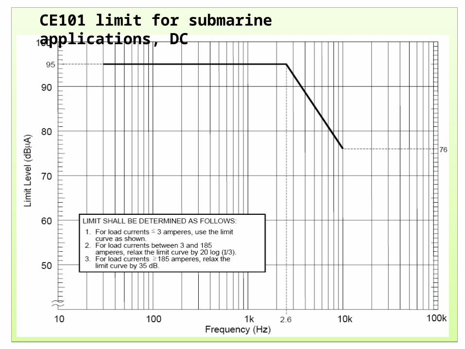
CE101 limit for submarine applications, DC
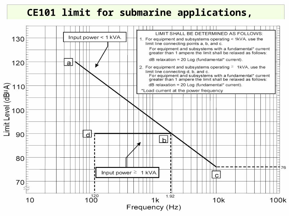
CE101 limit for submarine applications, 50 Hz
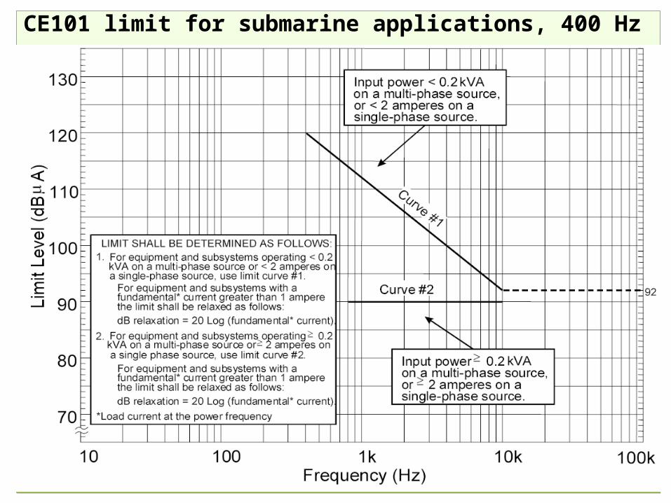
CE101 limit for submarine applications, 400 Hz
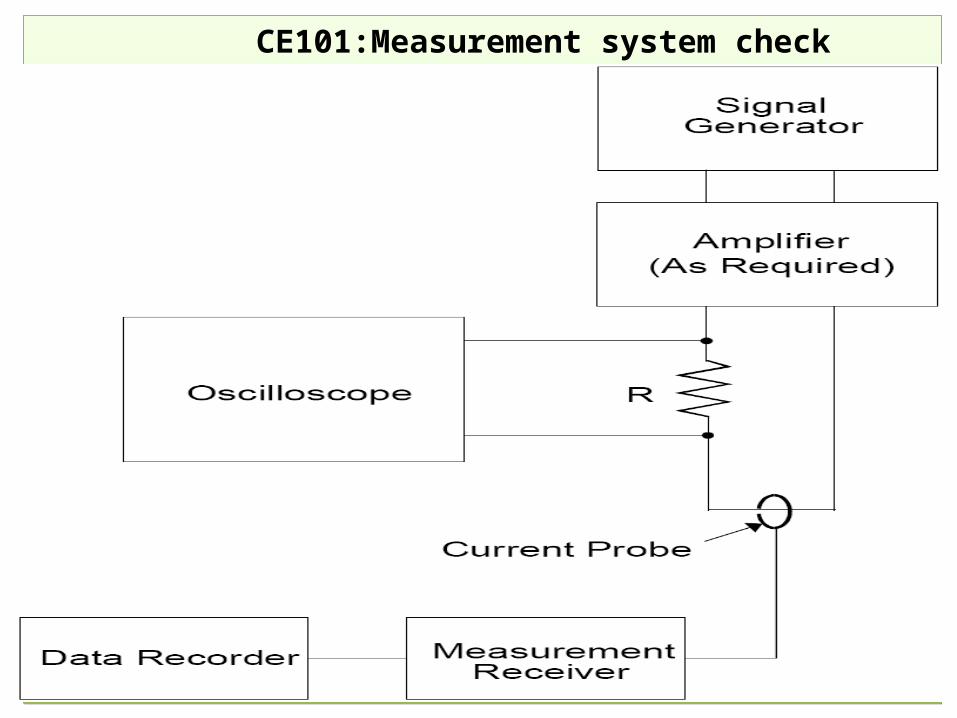
CE101:Measurement system check
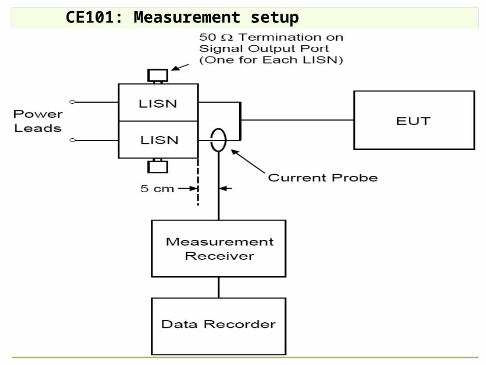
CE101: Measurement setup
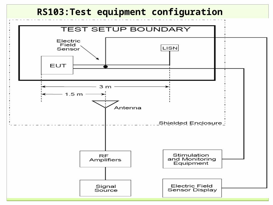
RS103:Test equipment configuration
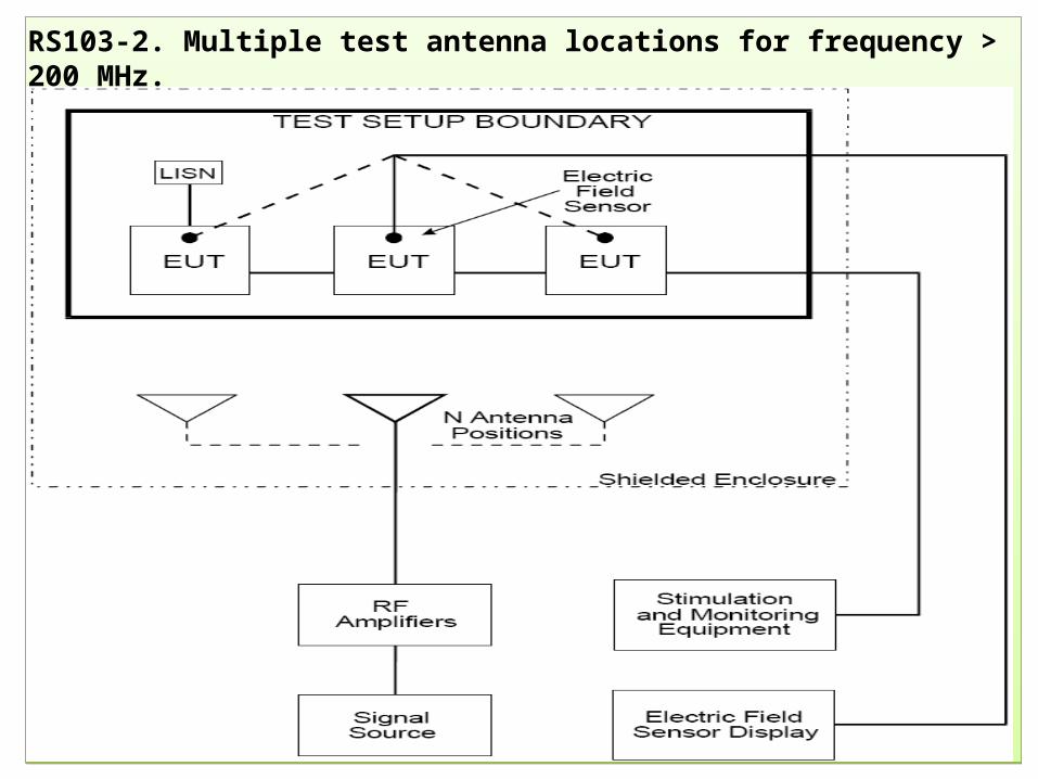
RS103-2. Multiple test antenna locations for frequency > 200 MHz.
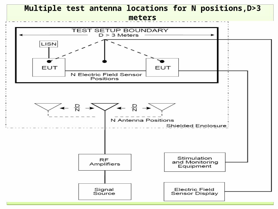
Multiple test antenna locations for N positions,D>3 meters
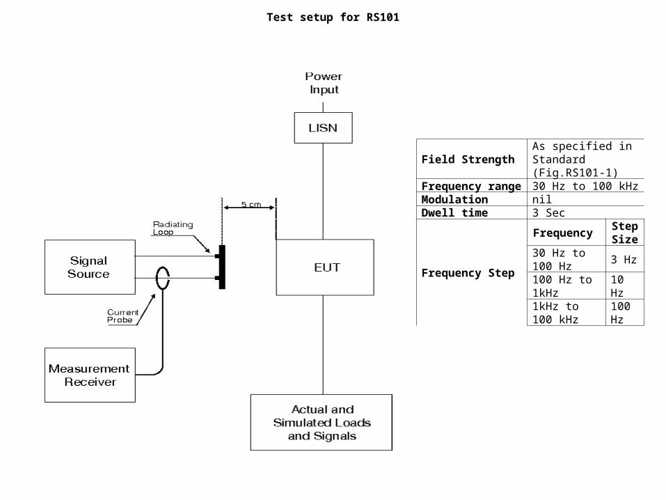
Test setup for RS101
Field StrengthAs specified in Standard (Fig.RS101-1)
Frequency range 30 Hz to 100 kHzModulation nilDwell time 3 Sec
Frequency Step
Frequency Step Size
30 Hz to 100 Hz
3 Hz
100 Hz to 1kHz
10 Hz
1kHz to 100 kHz
100 Hz
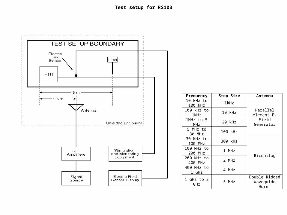
Frequency Step Size Antenna10 kHz to 100
kHz1kHz
Parallel element E-Field Generator
100 kHz to 1MHz
10 kHz
1MHz to 5 MHz
20 kHz
5 MHz to 30 MHz
100 kHz
30 MHz to 100 MHz
300 kHz
Biconilog
100 MHz to 200 MHz
1 MHz
200 MHz to 400 MHz
2 MHz
400 MHz to 1 GHz
4 MHz
1 GHz to 3 GHz
5 MHzDouble Ridged
Waveguide Horn
Test setup for RS103
Subrange DetectorsIF
BandwidthStep Size Antenna
CommentsMeas. Time
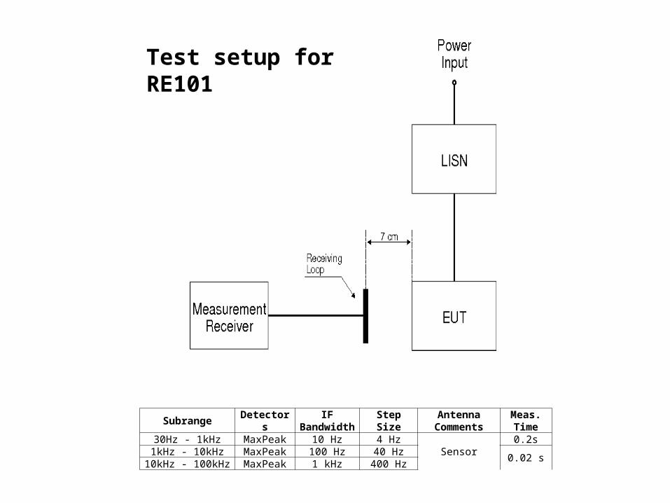
30Hz - 1kHz MaxPeak 10 Hz 4 HzSensor
0.2s1kHz - 10kHz MaxPeak 100 Hz 40 Hz
0.02 s10kHz - 100kHz MaxPeak 1 kHz 400 Hz
Test setup for RE101
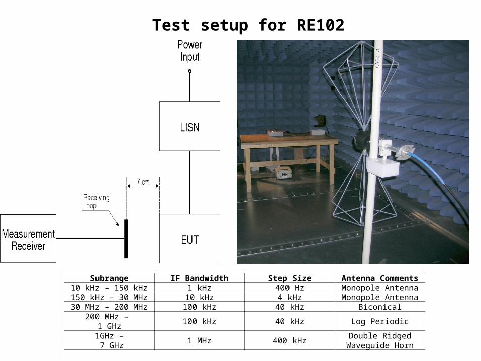
Subrange IF Bandwidth Step Size Antenna Comments10 kHz – 150 kHz 1 kHz 400 Hz Monopole Antenna150 kHz – 30 MHz 10 kHz 4 kHz Monopole Antenna30 MHz – 200 MHz 100 kHz 40 kHz Biconical
200 MHz – 1 GHz
100 kHz 40 kHz Log Periodic
1GHz – 7 GHz
1 MHz 400 kHzDouble Ridged
Waveguide Horn
Test setup for RE102
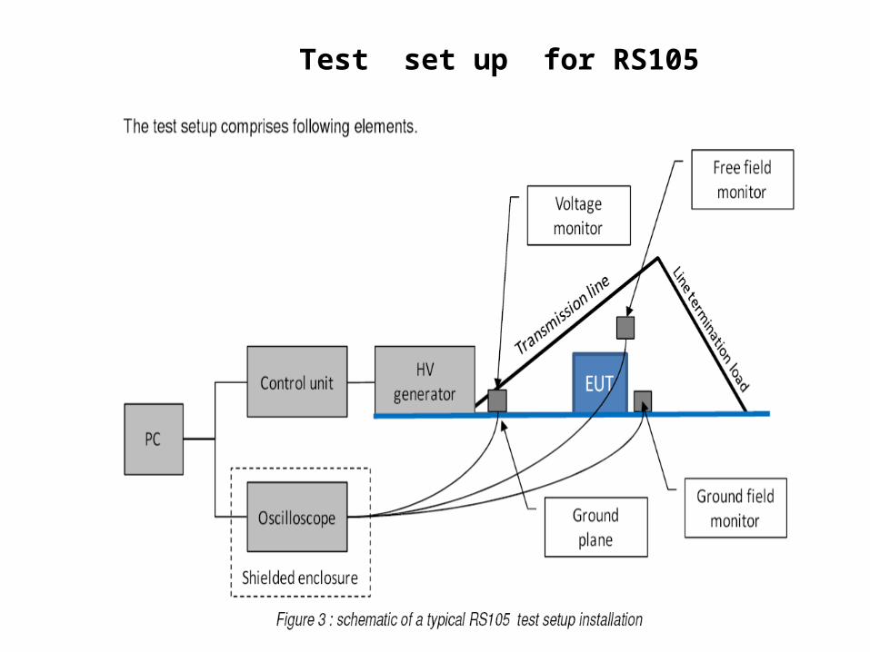
Test set up for RS105
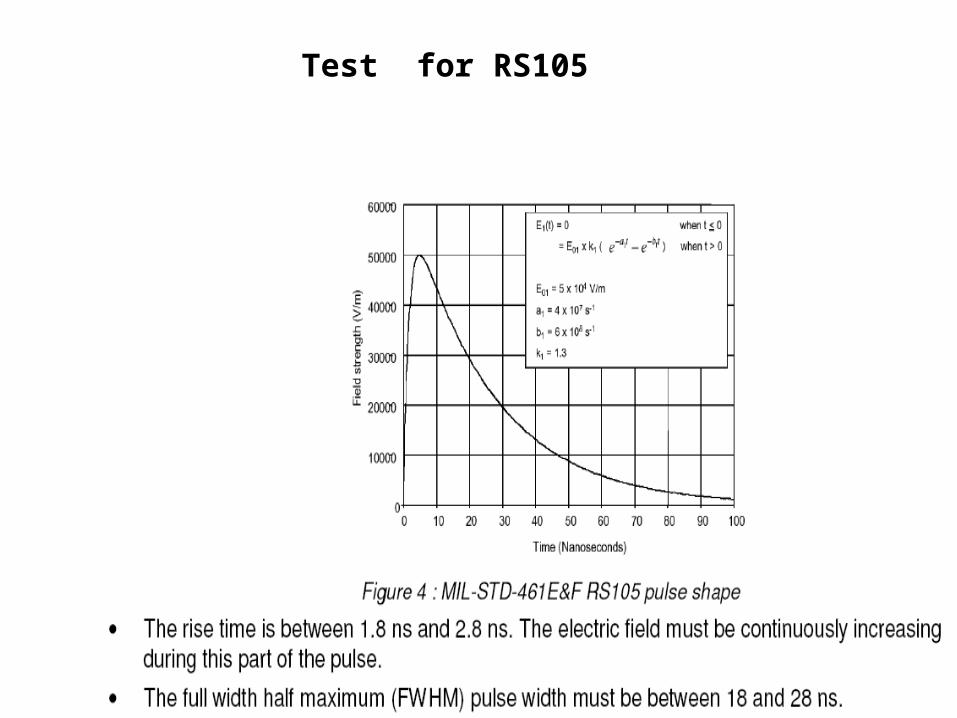
Test for RS105


![Analysis and Optimized Design of a Distributed Multi-Stage ...oa.upm.es/20894/1/INVE_MEM_2012_131624.pdf · aerospace applications, the military standard MIL-STD-461E [6] is applicable](https://img.pdfslide.us/doc/110x75/6119d7f30fce3e30ab15e0f4/analysis-and-optimized-design-of-a-distributed-multi-stage-oaupmes208941invemem2012.jpg)