Embed Size (px)
Citation preview
2.ALU Design Olle Seger ([email protected]) Dake Liu ([email protected])
Oscar Gustafsson ([email protected])
1
•ALU, an overview •AU, a case study •Exercises •About Lab-2

ALU Key component in datapath of a DSP Processor Usually all operands from RF, except imm Execution Cost : 1 Clock Cycle Use one guard bit
Key Components of ALU Arithmetic Unit Logic Unit (AND, OR, XOR etc) Shifter (LRS, LLS, ASR, ASL) Special Functions (e.g. bit manipulation) Multiplexers
2

ALU Overview
Logic Shift Special
Flags
AU
Pre-Processing
Post- Processing
Result Saturation
3
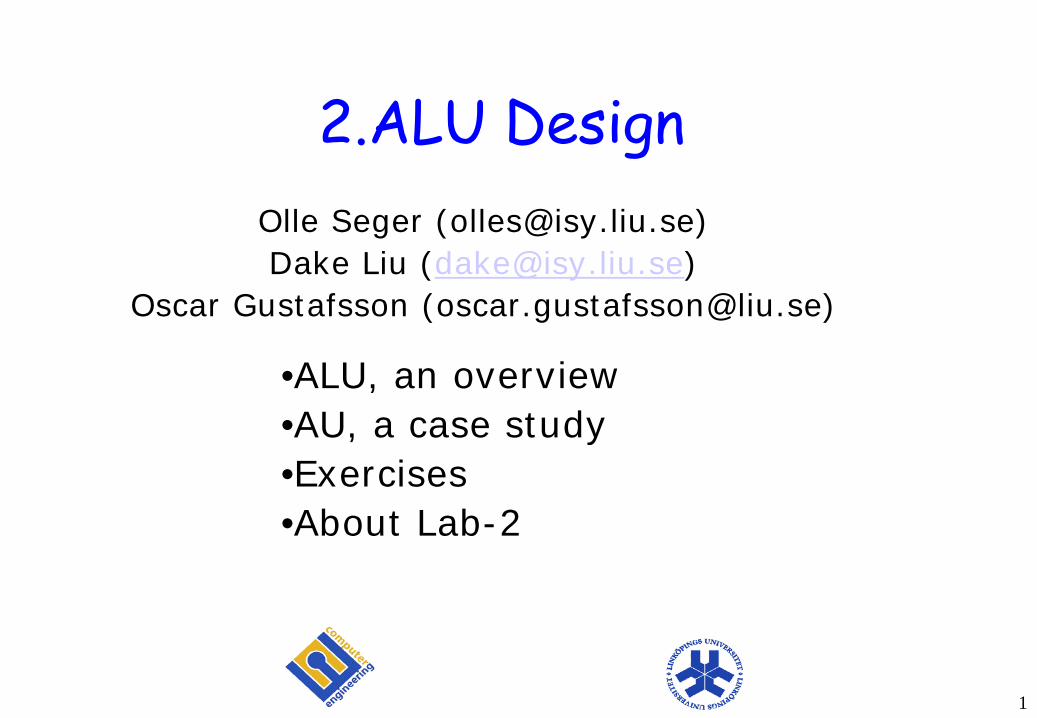
Let’s design a small AU Functional Specification 0. A + B with saturation OP=0000 1. A + B without saturation OP=0001 2. A + B + Cin with saturation OP=0010 3. A + B + Cin without saturation OP=0011 4. A - B with saturation OP=0100 5. A - B without saturation OP=0101 6. A compare to B with saturation OP=0110 7. ABS(A) Absolute operation on A OP=0111 8. NEG(A) Negate operation on A OP=1000 9. (A+B)/2 Average operation OP=1001 10. NOP OP=1010 The C, Z, V, and N flag should be updated for OP0-9
4
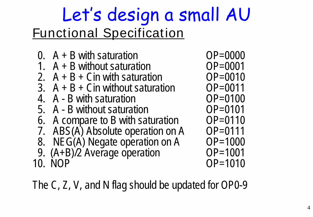
AU functions
A
B
A
B
Saturation
+
A
B
+
+
+
A
B
Cin
Cin
SAT(A + B)
A + B
SAT(A + B + C)
A + B +C
Saturation
Average (A+B)
+
A
B
‘1’
+
A
B
‘1’ Flag-only
+
A
B
‘1’
+
A
B=0
MSB of A
0 1
+
A
B=0
‘1’
ASR
+
A
B
SAT(A -B)
A - B
compare
ABS(A)
NEG(A)
Saturation
5

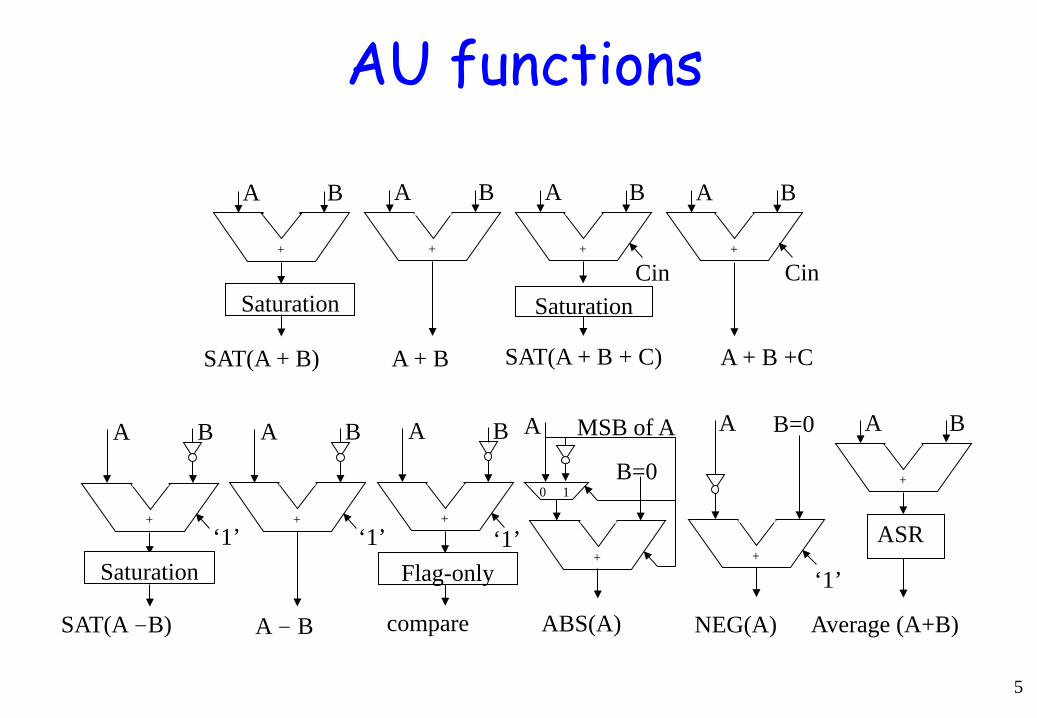
HW with multiplexing
6
C1
=1
A[15] A[15:0] B[15:0]
1 0
C A[15]
ASR SAT
C4
C3
DEC C1 C2 C3 C4
OP
00 01 10
00 01 10
11 10 01 00
Flags
17-bit adder
C5
C5
0 1
Cin Cout = S[16]
S
R
C2
0
00 01 10
trunc

7
HW with multiplexing always @(posedge clk) if (c5) begin C <= Cout; Z <= !|R; N <= R[15]; V <= (S[16] != S[15]); end
Flags
ASR ½ assign R = S[16:1];
always @(*) if (S[16]==S[15]) R <= S[15:0]; else if (S[16]==0) R <= 16’h7fff; else R <= 16’h8000;
Sat
DEC
OP C1 C2 C3 C4 C5 0 Sat(A+B) 00 00 00 00 1 1 A+B 00 00 00 01 1 2 Sat(A+B+C) 00 00 10 00 1 3 A+B+C 00 00 10 01 1 4 A-B 00 01 01 01 1 5 Sat(A-B) 00 01 01 00 1 6 Cmp(A,B) 00 01 01 - 1 7 Abs(A) 10 10 11 01 1 8 Neg(A) 01 10 01 01 1 9 (A+B)/2 00 00 00 10 1 10 NOP - - - 0
Trunc assign R = S[15:0];
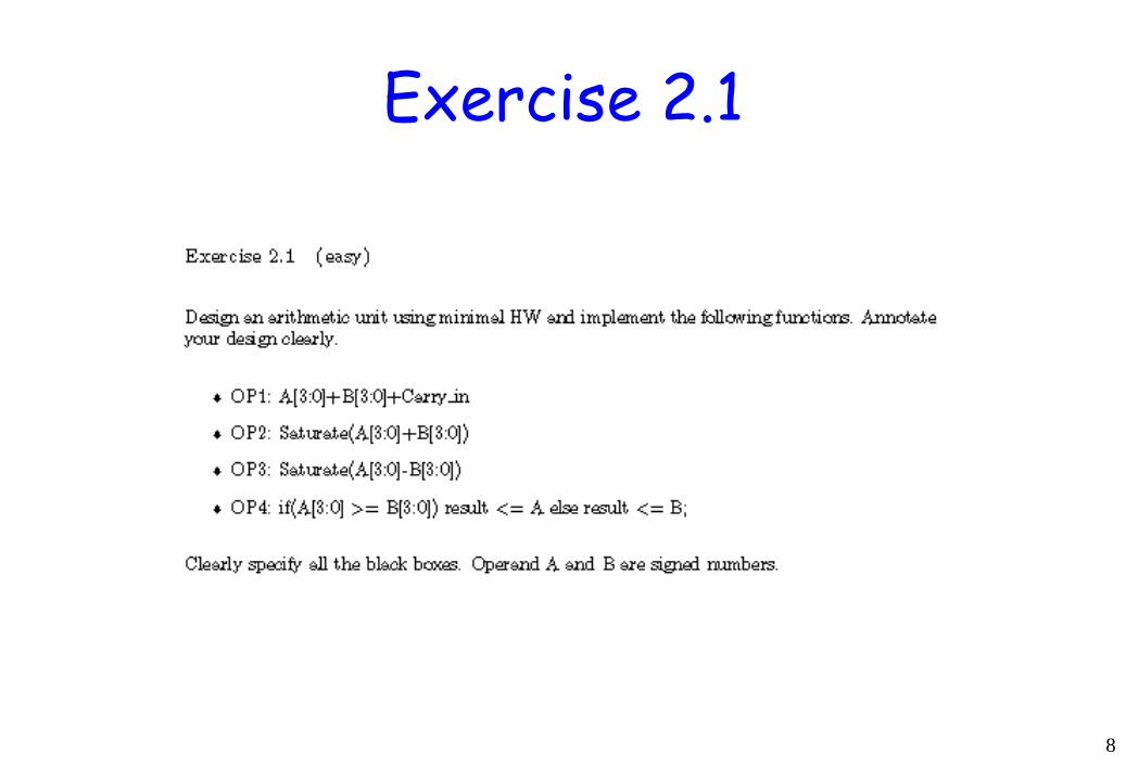
Exercise 2.1
8
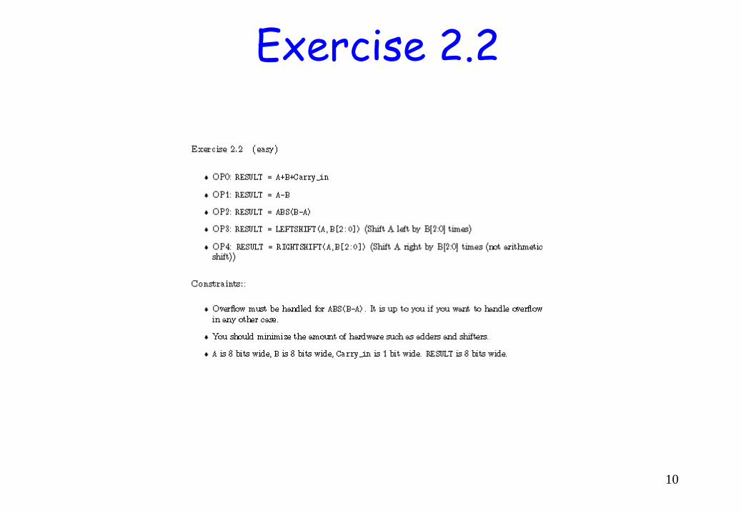
Exercise 2.2
10

11
We have a processor with a pipeline where we can: * Read out two operands from the register file and write one operand to the register file, all at the same time * Instead of reading out one of the operands you can choose to take a 16-bit immediate from the instruction word * We have 32 16-bit registers * A conditional branch takes 3 clock cycles * We have a repeat instruction * We have only one load instruction of interest: load Rd, DM0[AR0++], AR0 is set with the instruction set AR0, Rs * The store instruction works the same way store DM0[AR0++],Rs * After a load instruction we must wait a clock cycle before we can use the result
Exercise 2.3
12
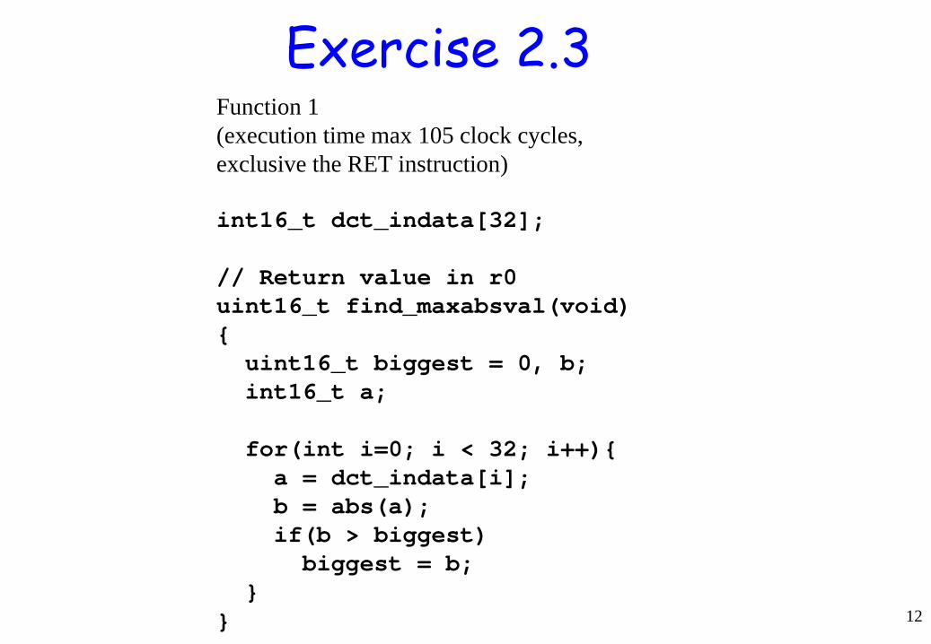
Function 1 (execution time max 105 clock cycles, exclusive the RET instruction) int16_t dct_indata[32]; // Return value in r0 uint16_t find_maxabsval(void) { uint16_t biggest = 0, b; int16_t a; for(int i=0; i < 32; i++){ a = dct_indata[i]; b = abs(a); if(b > biggest) biggest = b; } }
Exercise 2.3
13
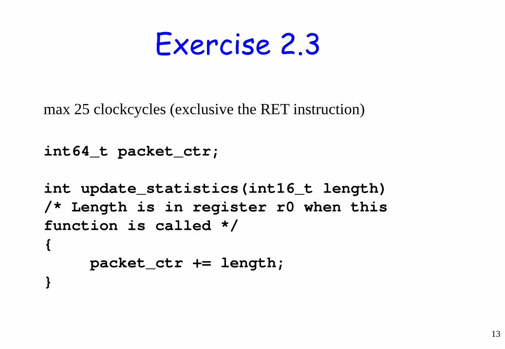
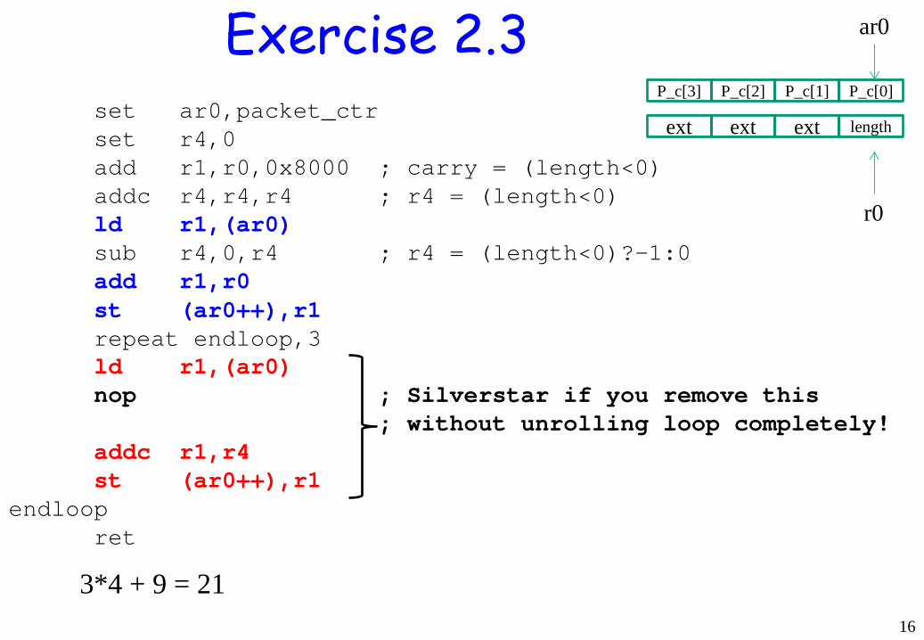
int64_t packet_ctr; int update_statistics(int16_t length) /* Length is in register r0 when this function is called */ { packet_ctr += length; }
max 25 clockcycles (exclusive the RET instruction)
Exercise 2.3
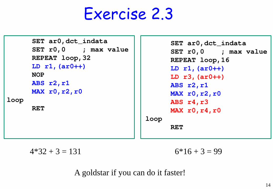
14
SET ar0,dct_indata SET r0,0 ; max value REPEAT loop,32 LD r1,(ar0++) NOP ABS r2,r1 MAX r0,r2,r0 loop RET
SET ar0,dct_indata SET r0,0 ; max value REPEAT loop,16 LD r1,(ar0++) LD r3,(ar0++) ABS r2,r1 MAX r0,r2,r0 ABS r4,r3 MAX r0,r4,r0 loop RET
4*32 + 3 = 131 6*16 + 3 = 99
A goldstar if you can do it faster!
Exercise 2.3
15
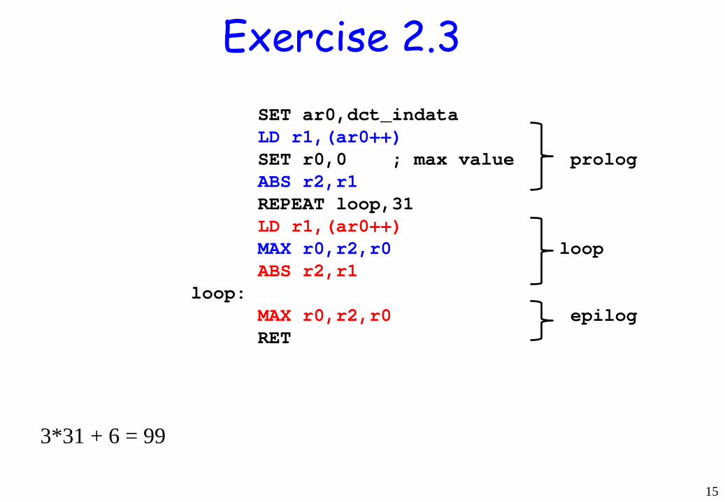
SET ar0,dct_indata LD r1,(ar0++) SET r0,0 ; max value prolog ABS r2,r1 REPEAT loop,31 LD r1,(ar0++) MAX r0,r2,r0 loop ABS r2,r1 loop: MAX r0,r2,r0 epilog RET
3*31 + 6 = 99
Exercise 2.3
16
set ar0,packet_ctr set r4,0 add r1,r0,0x8000 ; carry = (length<0) addc r4,r4,r4 ; r4 = (length<0) ld r1,(ar0) sub r4,0,r4 ; r4 = (length<0)?-1:0 add r1,r0 st (ar0++),r1 repeat endloop,3 ld r1,(ar0) nop ; Silverstar if you remove this ; without unrolling loop completely! addc r1,r4 st (ar0++),r1 endloop ret
P_c[0]
ext length
P_c[1] P_c[2] P_c[3]
ar0
ext ext
r0
Exercise 2.3
3*4 + 9 = 21

17
set ar0,packet_ctr set r4,0 add r1,r0,0x8000 ; carry = (length<0) addc r4,r4,r4 ; 1 in r4 if length<0 ld r1,(ar0) sub r4,0,r4 ; -1 in r4 if neg add r2,r1,r0 repeat endloop,3 ld r1,(ar0+1) st (ar0++),r2 ; loop addc r2,r1,r4 endloop st (ar0++),r2 ret
Exercise 2.3 software pipelining
3*3 + 9 = 18

ALU
18
C1 C2 C3 C4 C5 ABS(A) 1 10 11 0 0 MAX(A,B) 0 01 00 1 0 A+B 0 00 01 0 1 A-B 0 01 00 0 1 A+B+C 0 00 10 0 1
17-bit adder
{B[15],B[15:0]}
00 01 10
{A[15],A[15:0]}
0 1
Cout
17
C1 C2
C4
=1
A[15]
0
0 1
A[15]
C3
11 10 01 00
C
10 00,01 11
always @(posedge clk) if (C5) begin C <= Cout; end
S
[15:0]
S[16] 1 2
Exercise 2.3
19
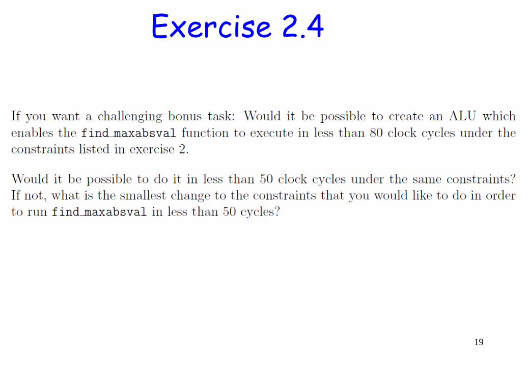
Exercise 2.4
20
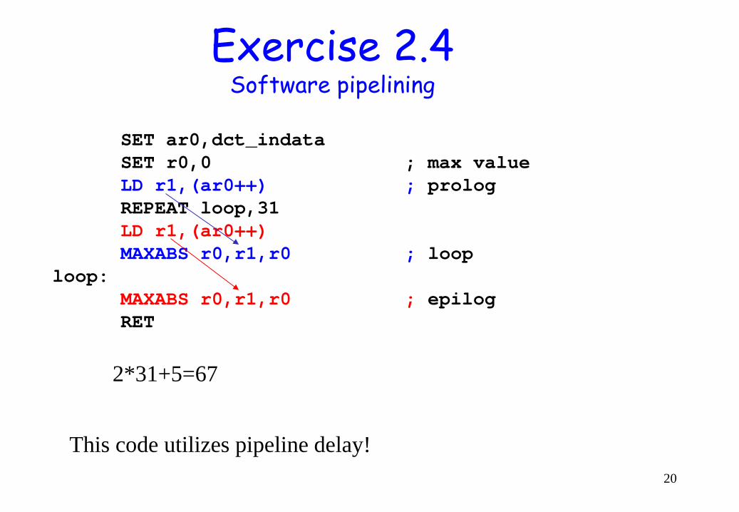
Exercise 2.4 Software pipelining
SET ar0,dct_indata SET r0,0 ; max value LD r1,(ar0++) ; prolog REPEAT loop,31 LD r1,(ar0++) MAXABS r0,r1,r0 ; loop loop: MAXABS r0,r1,r0 ; epilog RET
2*31+5=67
This code utilizes pipeline delay!
21
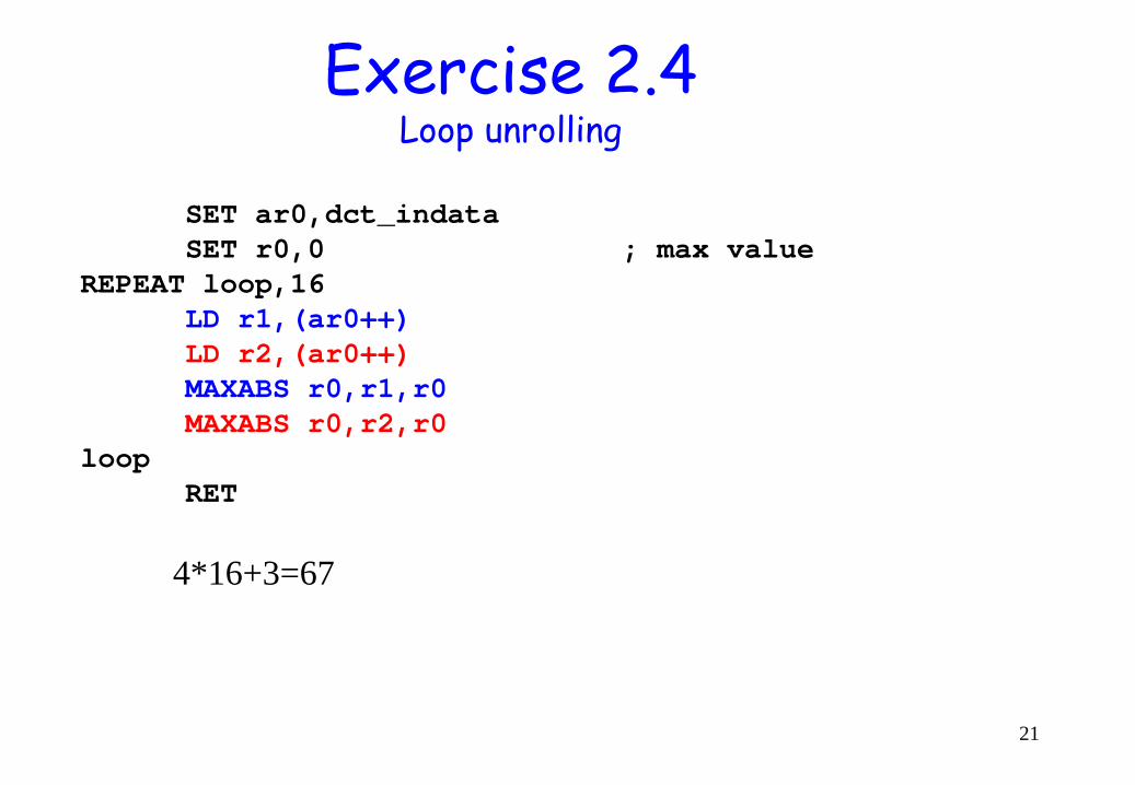
Exercise 2.4 Loop unrolling
SET ar0,dct_indata SET r0,0 ; max value REPEAT loop,16 LD r1,(ar0++) LD r2,(ar0++) MAXABS r0,r1,r0 MAXABS r0,r2,r0 loop RET
4*16+3=67

About Lab 2 (Datapath) • Manual for Lab 2 (Ch-2) • Source code for LAB-2 • You can use Verilog or VHDL. • Go through Ch-0 and Ch-2 for all details
Read the manuals carefully before starting the labs!
22
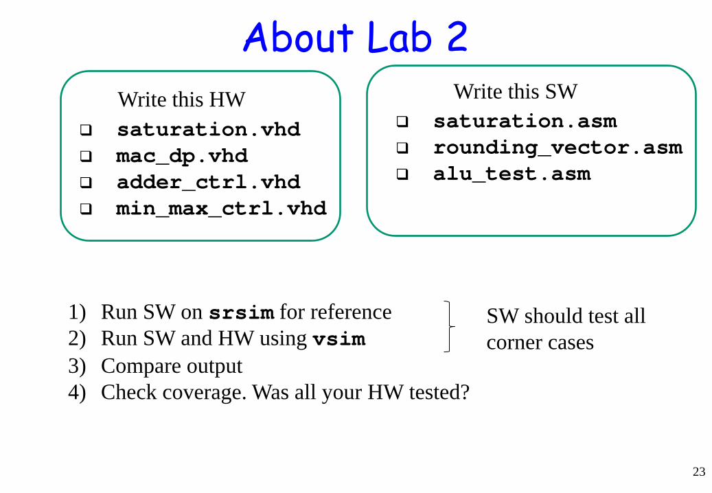
About Lab 2
saturation.vhd mac_dp.vhd adder_ctrl.vhd min_max_ctrl.vhd
23
saturation.asm rounding_vector.asm alu_test.asm
Write this HW Write this SW
1) Run SW on srsim for reference 2) Run SW and HW using vsim 3) Compare output 4) Check coverage. Was all your HW tested?
SW should test all corner cases
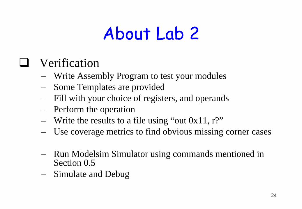
About Lab 2 Verification
– Write Assembly Program to test your modules – Some Templates are provided – Fill with your choice of registers, and operands – Perform the operation – Write the results to a file using “out 0x11, r?” – Use coverage metrics to find obvious missing corner cases
– Run Modelsim Simulator using commands mentioned in
Section 0.5 – Simulate and Debug
24
![Challenge SSTIC 2017ChallengeSSTIC2017 3 DON’T LET HIM ESCAPE! 067: ldxdw r1, [r10+0xffe0];offset=&payload[12] 068: ldindw r1, 0x0 069: xor64 r0, 0xffffffff 06a: lsh64 r0, 0x20](https://img.pdfslide.us/doc/110x75/600c34053801427cbb078a48/challenge-sstic-2017-challengesstic2017-3-donat-let-him-escape-067-ldxdw-r1.jpg)
![LLVM MC in Practice · 2019. 10. 30. · _fac: push {r4, r7, lr} ldr! r0, [pc, #20] mov r1, #1 add r7, sp, #4 ldr! r0, [pc, r0] mov! r2, r1 ldr! r0, [r0] b! #0 # 4 bytes of data:.long](https://img.pdfslide.us/doc/110x75/60c63395503ad85a6a26c0e3/llvm-mc-in-practice-2019-10-30-fac-push-r4-r7-lr-ldr-r0-pc-20-mov.jpg)


![A Memory Consistency Model For RISC-V...T0 T1 T2 T3 st [x] ç 1 st [y] ç 1 ld x à [r0] ld y à [r2] F R, R F R, R ld y à [r1] ld x à [r3] Non-SC Outcome: r0=1, r1=0, r2=1, r3=0](https://img.pdfslide.us/doc/110x75/5f32b1ec6699724c863b6abd/a-memory-consistency-model-for-risc-v-t0-t1-t2-t3-st-x-1-st-y-1-ld.jpg)