Embed Size (px)
Citation preview
299
Chapter 11
Rural buildings
IntRoductIonThe traditional lifestyle of the rural communities of tropical Africa is undergoing many changes. People are becoming better educated, coming into contact with other cultures and technologies, and gradually losing their knowledge of the traditional crafts and agricultural methods that were practised by their ancestors. This is an encouraging change from the traditional way of life to a more modern way of life with a desire for appropriate dwellings.
Planning the design and construction of a rural dwelling requires decisions with which the rural family must live for a long time, perhaps a lifetime. These decisions are likely to be highly personal because of individual preferences, financial situation, family size, location and other circumstances. There are a number of factors to be considered and questions to be answered before building a home.
This chapter presents information relating to space requirements, together with ideas for planning rural dwellings. It leaves a great deal of opportunity for designs to evolve through the cooperation of the rural family, craftsmen and, perhaps, engineers and architects. The planning will involve careful evaluation of factors such as traditional family culture and social life, climate, government regulations, available materials and the skills of local craftsmen.
The planning process will result in unique designs that may differ greatly from one area to another. However, only a planning process that aims to produce designs that are general in terms of layout, materials, construction and details – within a cultural and environmental context – can contribute to the development of an indigenous building tradition that pursues the native architectural heritage.
Space RequIRementSIn planning a rural home, adequate space must be allowed for each of the daily activities. This is not so much related to total space as it is to such things as door widths and heights, corridor widths, adequate space for a bed or a table and chairs and clearance for a door to swing open. It is essential for these dimensions to be checked in every design, as very minimal changes can often make a considerable difference in terms of convenience. Figure 11.1, as well as several figures in the Section ‘Functional Requirements for different rooms and spaces’, provides a guide to space requirements.
Figure 11.1 critical human space requirements
FamIly cultuRal and SocIal RequIRementS Various tribes and ethnic groups with different cultural and religious backgrounds have developed distinctive customs and social requirements. An analysis of the rural family’s daily life, including present requirements and future plans, will help in selecting the important factors for designing an appropriate dwelling house.
A number of questions relevant to rural home design are listed below:
Family size: How many persons will live in the house initially and in the future? What are the family relationships: age, sex, marital status?
Sleeping: Are separate bedrooms and/or houses needed for the husband and wife (wives)? Where do small children sleep: in the parent’s room or a separate room nearby? Where do the older children sleep: in
400
1 000 1 200 600-750
600
Min. corridor width for one person
Min. corridor width for two persons
870
750-
800
450-
480
870
750
620
400-
450
1 20025
0 -
350
Office chair Dining chair Arm chair
Door opening to corridor
800 1 000 1 200
300 Rural structures in the tropics: design and development
a separate room or a separate house? Are children of different sexes segregated?
Cooking/eating: Does cooking take place inside or outside the house, or in a separate structure? Do cooking and eating take place in the same area? Is there a separation between women and men, children or visitors, during mealtimes? What kinds of water resources are available?
Store: How much food is stored, and where? What types of storage conditions are required? What other items need to be stored – fuel, water, implements?
Resting/conversation: What kind of room is required for resting and conversation: an outside verandah or separate shelter, or an inside kitchen or living room? Are men, women and children separated during these activities?
SpecIal RequIRementS oF RuRal dwellIngS Rural families accustomed to working with nature have different needs in a dwelling from those of families in an urban situation. Although many of the basic requirements are the same for both rural and urban homes, additional factors must be considered when designing a rural dwelling. These include:
• A site that is well drained but suitable for a well and, where necessary, either a latrine or a septic tank and drainage field. A home should never be built on a flood plain.
• How the dwelling relates to other rural buildings to provide a view of the access road and the farmstead.
• The correct orientation of the house to give protection against sun, rain, odour and dust, while providing for ventilation, a view and easy access. An east–west orientation to provide the maximum shade is a general rule. However, it may sometimes be desirable to modify this to take advantage of a prevailing wind for better ventilation or to allow more sun penetration into the house in cool highland areas. See Figure 11.2.
• A design that will enable the house to be built in stages according to the availability of finances.
• Flexibility in the arrangement of rooms to allow for alternative uses and future expansion.
• A kitchen large enough to allow for space-consuming activities, such as cutting meat after slaughter and preparation of homegrown vegetables.
• A separate entrance from the backyard into the kitchen area. A small verandah at the rear of the home where some of the kitchen work can be carried out, and perhaps rural/work clothes can be stored.
• A verandah large enough to allow for activities such as eating, resting and receiving visitors. The verandah, along with windows and ventilation openings, may need to be protected against insects with mosquito netting.
• A separate office for larger farms, while a storage cupboard and the dining table will be sufficient for small farms.
• A place to store dirty farm clothes and shoes, combined with washing facilities if possible.
• A guest room if it is likely to be needed.
Figure 11.2 orientation of a rural dwelling
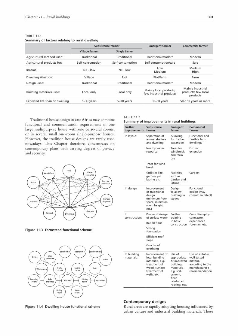
categoRIeS oF RuRal houSeSRural communities may be grouped according to the type of agriculture practised in the area: subsistance, emergent or commercial. The size of the home, the materials used and the method of construction will be influenced by the type of agriculture and the resulting income. The dwelling may range from a self-built structure using local, natural materials and costing little or nothing, to a contractor-built house using mostly commercial building materials and requiring a considerable income to finance. Table 11.1 summarizes various factors relating to housing for the three categories of rural families.
Improvements in layout, design, construction and building materials may allow further development of the rural dwelling; it will also help to extend the lifespan of the dwelling house and make life more comfortable. Table 11.2 summarizes some of the improvements to be expected.
FunctIon and communIcatIon SchemeSGood communications play an important role in the successful management of a farm business. Close supervision and control will help to maximize profits and keep losses to a minimum. Therefore, easy access to ongoing farm activities is imperative. A functionally placed dwelling will serve as a communication centre within the farmstead and will help the farmer to supervise farm operations. Figure 11.3 is a graphic depiction of the dwelling as the centre of farmstead operations.
The human environment and traditional social life have a strong influence on the functional arrangement of rooms within a dwelling. Figure 11.4 attempts to show functional communication between rooms with the essential interconnections.
SUN SUN
N
W E
S
Control view
Cookingeating
Sleeping
Sleeping
Verandah
Farm dwelling
Entrance
Prevailing wind
Main rain
Attractive view
301Chapter 11 – Rural buildings
Traditional house design in east Africa may combine functional and communication requirements in one large multipurpose house with one or several rooms, or in several small one-room single-purpose houses. However, the tradition house designs are rarely used nowadays. This Chapter therefore, concentrates on contemporary plans with varying degrees of privacy and security.
Figure 11.3 Farmstead functional scheme
Figure 11.4 dwelling house functional scheme
Carpark
Livestock
Store
WorkshopField
DwellingGarden
Refusedisposal
Energyresource
Waterresource
Office
Washroom Bath
Toilet
Bedroom IIIBedroom IIBedroom I
Kitchen Verandah
Mainentrance
Sideentrance
Diningroom
Storeroom
Dressingroom
Livingroom
Utilityroom
Hall /Corridor
Table 11.2Summary of improvements in rural buildings
Further improvements
Subsistence farmer
emergent farmer
commercial farmer
In layout: Separation of animal shelters and dwelling
allowing for further expansion
Functional and flexible farm dwellings
Nearby water resource
Trees for windbreak and farm use
Future extension
Trees for wind break
facilities like garden, pit latrine etc.
Facilities such as garden and latrine
Carport
In design: Improvement of traditional design (minimum floor space, minimum room height, etc.)
Design to allow building in stages
Functional design (may consult architect)
In construction:
Proper drainage of surface water
Raised floor
Strong foundation
efficient roof slope
Good roof overhang
Further training in basic construction
Consult/employ contractor, experienced foreman, etc.
In building materials:
Improvement of local building materials, e.g. treatment of wood, surface treatment of walls, etc.
Use of appropriate or improved building materials, e.g. soil-cement, fibre-reinforced roofing, etc.
Use of suitable, well-tested material according to the manufacturer's recommendation
contemporary designsRural areas are rapidly adopting housing influenced by urban culture and industrial building materials. These
Table 11.1Summary of factors relating to rural dwelling
Subsistence farmer emergent farmer
commercial farmer
Village farmer Single famer
agricultural method used: Traditional Traditional Traditional/modern Modern
agricultural products for: Self-consumption Self-consumption Self-consumption/sale Sale
Income: Nil - low Nil - low low Medium
Medium High
Dwelling situation: Village Plot Plot/farm Farm
Design used: Traditional Traditional Traditional/modern Modern
building materials used: local only local only Mainly local products; few industrial products
Mainly industrial products; few local
products
expected life span of dwelling 5–30 years 5–30 years 30–50 years 50–150 years or more
302 Rural structures in the tropics: design and development
designs combine the advantages of privacy, security and improved health conditions without excessive expense for building materials or skilled craftsmen.
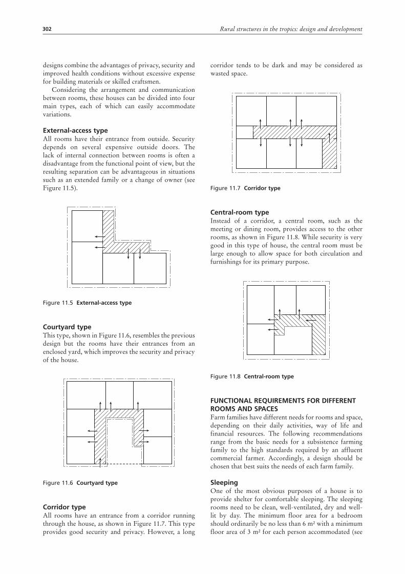
Considering the arrangement and communication between rooms, these houses can be divided into four main types, each of which can easily accommodate variations.
external-access typeAll rooms have their entrance from outside. Security depends on several expensive outside doors. The lack of internal connection between rooms is often a disadvantage from the functional point of view, but the resulting separation can be advantageous in situations such as an extended family or a change of owner (see Figure 11.5).
Figure 11.5 external-access type
courtyard typeThis type, shown in Figure 11.6, resembles the previous design but the rooms have their entrances from an enclosed yard, which improves the security and privacy of the house.
Figure 11.6 courtyard type
corridor typeAll rooms have an entrance from a corridor running through the house, as shown in Figure 11.7. This type provides good security and privacy. However, a long
corridor tends to be dark and may be considered as wasted space.
Figure 11.7 corridor type
central-room typeInstead of a corridor, a central room, such as the meeting or dining room, provides access to the other rooms, as shown in Figure 11.8. While security is very good in this type of house, the central room must be large enough to allow space for both circulation and furnishings for its primary purpose.
Figure 11.8 central-room type
FunctIonal RequIRementS FoR dIFFeRent RoomS and SpaceSFarm families have different needs for rooms and space, depending on their daily activities, way of life and financial resources. The following recommendations range from the basic needs for a subsistence farming family to the high standards required by an affluent commercial farmer. Accordingly, a design should be chosen that best suits the needs of each farm family.
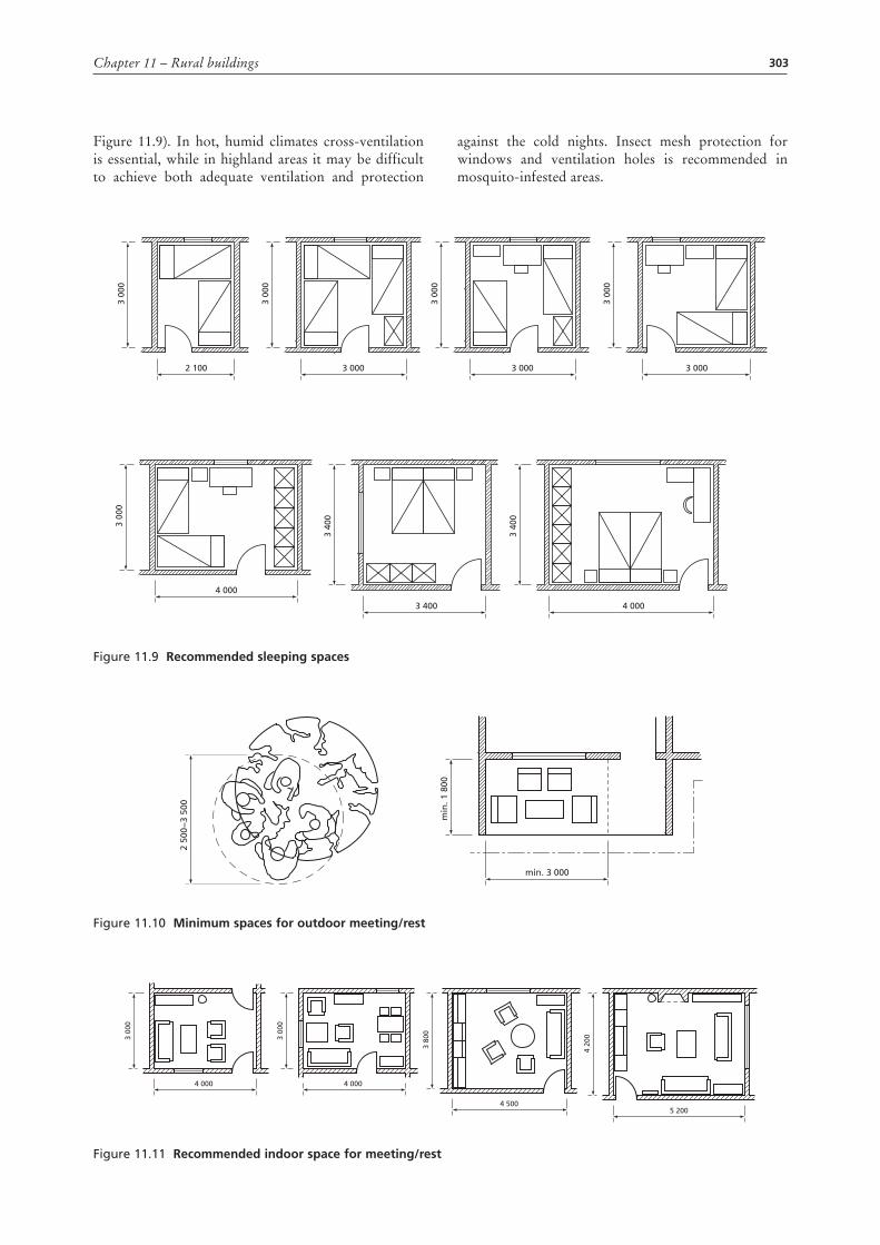
SleepingOne of the most obvious purposes of a house is to provide shelter for comfortable sleeping. The sleeping rooms need to be clean, well-ventilated, dry and well-lit by day. The minimum floor area for a bedroom should ordinarily be no less than 6 m² with a minimum floor area of 3 m² for each person accommodated (see
303Chapter 11 – Rural buildings
Figure 11.9). In hot, humid climates cross-ventilation is essential, while in highland areas it may be difficult to achieve both adequate ventilation and protection
against the cold nights. Insect mesh protection for windows and ventilation holes is recommended in mosquito-infested areas.
Figure 11.9 Recommended sleeping spaces
3 00
0
2 100
3 00
0
3 00
0
3 000
3 00
0
3 000 3 000
3 00
0
4 000
3 40
0
3 400
3 40
0
4 000
Figure 11.10 minimum spaces for outdoor meeting/rest
min
. 1 8
00
2 50
0−3
500
min. 3 000
Figure 11.11 Recommended indoor space for meeting/rest
3 00
0
4 000
3 00
0
4 000
3 80
0
4 5005 200
4 20
0
304 Rural structures in the tropics: design and development
meeting and restAn important facet of African daily life is a place to meet to talk with family and friends or simply to sit down to rest. To a large extent, this activity takes place outdoors in the shade of a tree, a separate shelter or a verandah. In order to function well, this outdoor space should not be less than the recommendation given in Figure 11.10.
There should also be some indoor space, such as a living room, for similar activities during the evening and in inclement weather. A room with a minimum floor space of 12–15 m², furnished with chairs and tables, will ordinarily be sufficient (see Figure 11.11). Although not an ideal solution, this room can be used for sleeping by children or older boys. If the room is to be more elaborately furnished, an increase in floor space of up to 25–30 m² may be needed. Cupboards, bookshelves, a television, fireplace and other amenities may be included.
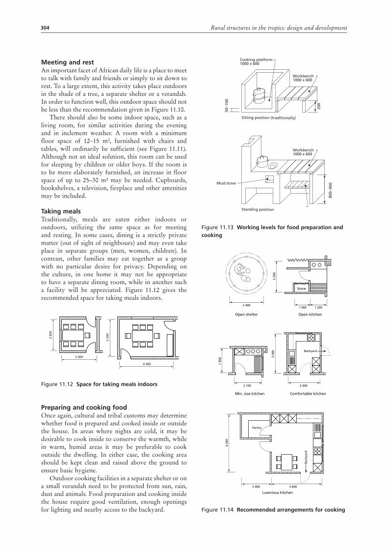
taking mealsTraditionally, meals are eaten either indoors or outdoors, utilizing the same space as for meeting and resting. In some cases, dining is a strictly private matter (out of sight of neighbours) and may even take place in separate groups (men, women, children). In contrast, other families may eat together as a group with no particular desire for privacy. Depending on the culture, in one home it may not be appropriate to have a separate dining room, while in another such a facility will be appreciated. Figure 11.12 gives the recommended space for taking meals indoors.
Figure 11.12 Space for taking meals indoors
preparing and cooking foodOnce again, cultural and tribal customs may determine whether food is prepared and cooked inside or outside the house. In areas where nights are cold, it may be desirable to cook inside to conserve the warmth, while in warm, humid areas it may be preferable to cook outside the dwelling. In either case, the cooking area should be kept clean and raised above the ground to ensure basic hygiene.
Outdoor cooking facilities in a separate shelter or on a small verandah need to be protected from sun, rain, dust and animals. Food preparation and cooking inside the house require good ventilation, enough openings for lighting and nearby access to the backyard.
2 60
0
3 000
3 20
0
4 400
Figure 11.13 working levels for food preparation and cooking
Figure 11.14 Recommended arrangements for cooking
Sitting position (traditionally)
Standing position
Cooking platform1000 x 600
Workbench1000 x 600
Workbench1000 x 600
Mud stove
50−
100
200
800−
900
2 4001 000 1 200
Open shelter Open kitchen
Store
2 20
0
2 100 2 400
Min. size kitchen
1 90
0
Backyard
Comfortable kitchen
3 00
0
Pantry
Bac
kyar
d
2 000 3 600
Luxerious kitchen
4 20
0
305Chapter 11 – Rural buildings
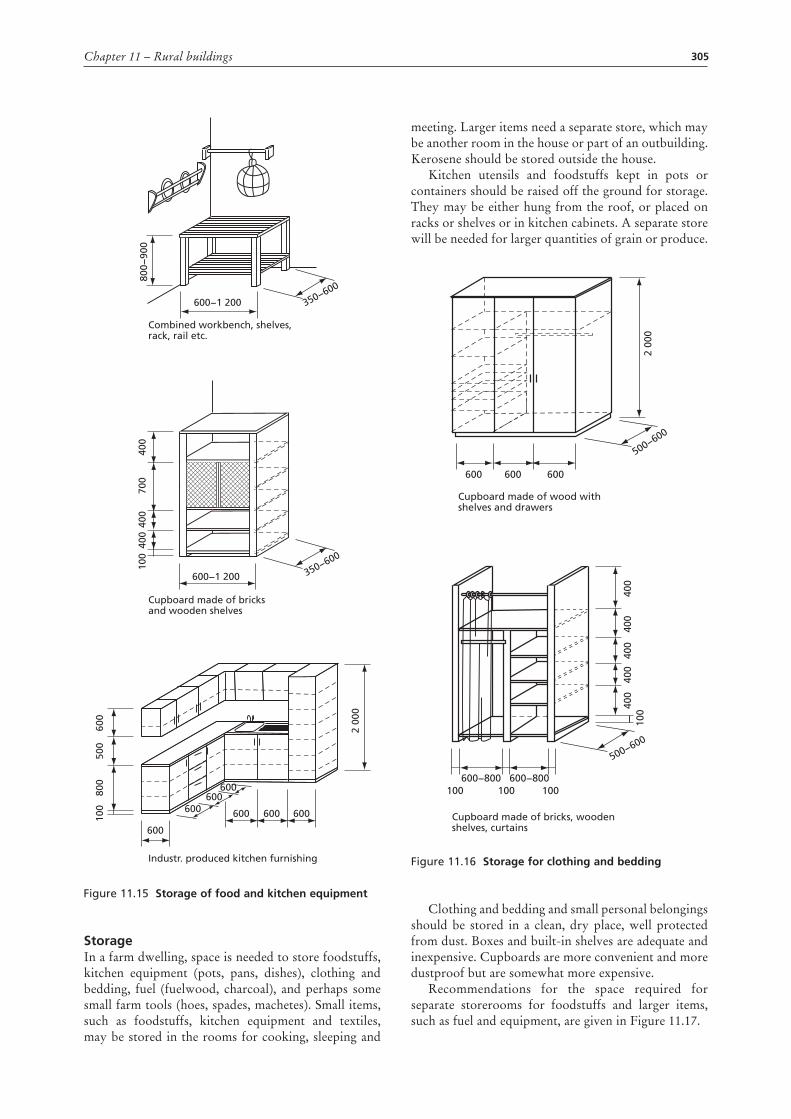
StorageIn a farm dwelling, space is needed to store foodstuffs, kitchen equipment (pots, pans, dishes), clothing and bedding, fuel (fuelwood, charcoal), and perhaps some small farm tools (hoes, spades, machetes). Small items, such as foodstuffs, kitchen equipment and textiles, may be stored in the rooms for cooking, sleeping and
meeting. Larger items need a separate store, which may be another room in the house or part of an outbuilding. Kerosene should be stored outside the house.
Kitchen utensils and foodstuffs kept in pots or containers should be raised off the ground for storage. They may be either hung from the roof, or placed on racks or shelves or in kitchen cabinets. A separate store will be needed for larger quantities of grain or produce.
Figure 11.16 Storage for clothing and bedding
Clothing and bedding and small personal belongings should be stored in a clean, dry place, well protected from dust. Boxes and built-in shelves are adequate and inexpensive. Cupboards are more convenient and more dustproof but are somewhat more expensive.
Recommendations for the space required for separate storerooms for foodstuffs and larger items, such as fuel and equipment, are given in Figure 11.17.
600
Cupboard made of wood withshelves and drawers
Cupboard made of bricks, woodenshelves, curtains
600 600
500−600
500−600
2 00
0
400
100
400
400
400
400
600−800 600−800100 100 100
600−1 200
Combined workbench, shelves, rack, rail etc.
Cupboard made of bricksand wooden shelves
Industr. produced kitchen furnishing
600−1 200
600
600600
600 600
600
600
350−600
350−600
800−
900
400
600
500
2 00
0
800
100
400
700
400
100
Figure 11.15 Storage of food and kitchen equipment
306 Rural structures in the tropics: design and development
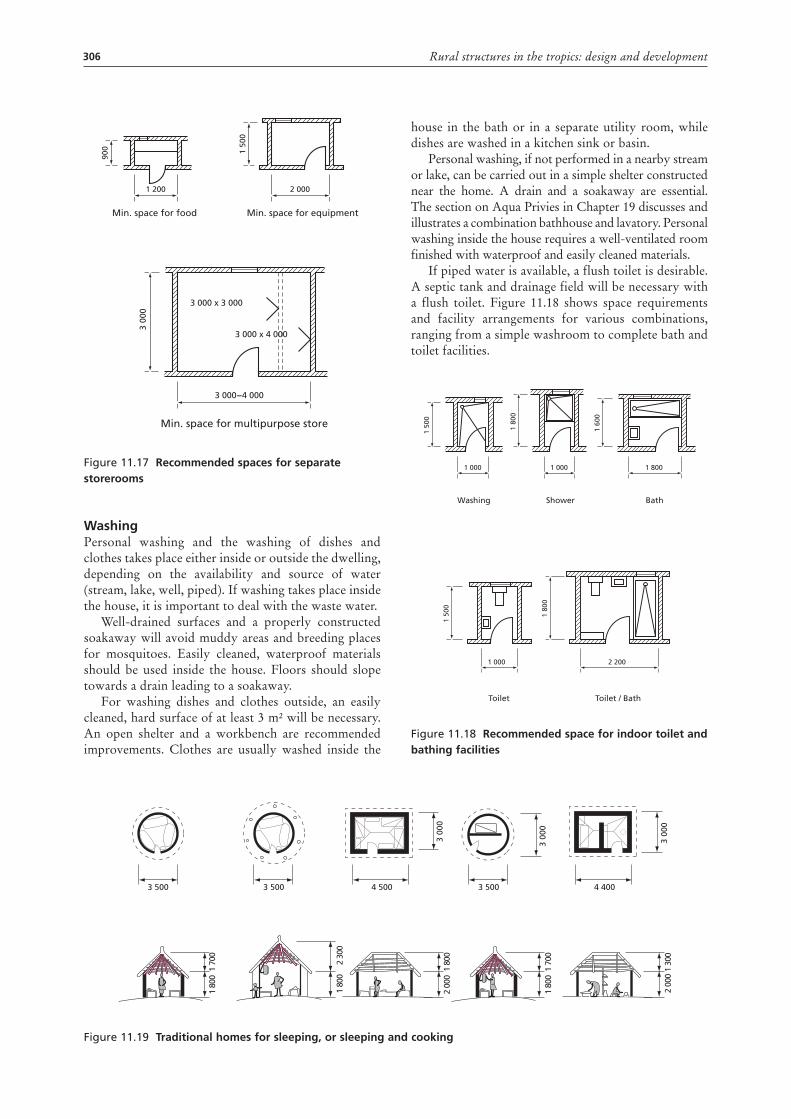
Figure 11.17 Recommended spaces for separate storerooms
washingPersonal washing and the washing of dishes and clothes takes place either inside or outside the dwelling, depending on the availability and source of water (stream, lake, well, piped). If washing takes place inside the house, it is important to deal with the waste water.
Well-drained surfaces and a properly constructed soakaway will avoid muddy areas and breeding places for mosquitoes. Easily cleaned, waterproof materials should be used inside the house. Floors should slope towards a drain leading to a soakaway.
For washing dishes and clothes outside, an easily cleaned, hard surface of at least 3 m² will be necessary. An open shelter and a workbench are recommended improvements. Clothes are usually washed inside the
1 200
Min. space for food
900
2 000
Min. space for equipment
1 50
0
3 000−4 000
Min. space for multipurpose store
3 000 x 3 000
3 000 x 4 000
3 00
0
house in the bath or in a separate utility room, while dishes are washed in a kitchen sink or basin.
Personal washing, if not performed in a nearby stream or lake, can be carried out in a simple shelter constructed near the home. A drain and a soakaway are essential. The section on Aqua Privies in Chapter 19 discusses and illustrates a combination bathhouse and lavatory. Personal washing inside the house requires a well-ventilated room finished with waterproof and easily cleaned materials.
If piped water is available, a flush toilet is desirable. A septic tank and drainage field will be necessary with a flush toilet. Figure 11.18 shows space requirements and facility arrangements for various combinations, ranging from a simple washroom to complete bath and toilet facilities.
Figure 11.18 Recommended space for indoor toilet and bathing facilities
1 000
Washing
1 50
0
1 000
Toilet
1 50
0
1 000
Shower1
800
1 800
Bath
1 60
0
2 200
Toilet / Bath
1 80
0
Figure 11.19 traditional homes for sleeping, or sleeping and cooking
3 500 3 500 3 500 4 4004 500
3 00
0
3 00
0
3 00
0
1 80
01
700
2 00
01
800
2 00
01
300
1 80
01
700
1 80
02
300
307Chapter 11 – Rural buildings
Reading and writingThe education level of the rural population is rising steadily, and places to read and write are becoming more necessary for the farm home, especially for children going to school. While the sleeping room may provide the best place in terms of privacy, the meeting room and verandah are possible, but less appropriate, places for intensive studying.
The farmer also needs a place to store documents and records and to attend to the farm business. The dining table, in combination with a cupboard, is sufficient for the small farmer, while on a large farm, a separate office with about 9 m² of floor space may be required. Good natural lighting and artificial lighting are essential wherever reading and writing are carried out.
entranceThe traditional African house has an entrance protected from wind, rain and sun by a roof overhang, which
also provides privacy for the family. In a low-cost farm dwelling the entrance may be combined with the verandah or the main meeting and resting room, and is often used for additional storage space for equipment, farm clothing, bicycles, etc. A larger, more modern farm dwelling should have at least two entrances: one at the front of the house where visitors are received and another near the kitchen or utility room that can be used for coming and going while performing daily tasks around the home and farmstead.
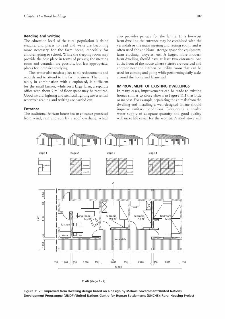
ImpRoVement oF exIStIng dwellIngSIn many cases, improvements can be made to existing homes similar to those shown in Figure 11.19, at little or no cost. For example, separating the animals from the dwelling and installing a well-designed latrine should improve sanitary conditions. Developing a nearby water supply of adequate quantity and good quality will make life easier for the women. A mud stove will
Figure 11.20 Improved farm dwelling design based on a design by malawi government/united nations development programme (undp)/united nations centre for human Settlements (unchS): Rural housing project
stage 1
livingroom bedroom
verandah
bedroom bedroom
verandah
kitchen
stage 2 stage 3 stage 4
store
kitchen
living room13.3 m2
bedroom
verandah
PLAN (stage 1 - 4)
AA
9.0 m2bedroom
7.2 m2bedroom
12.3 m2
1 05
04
100
6 50
0
1 05
015
015
0
1 200 3 000
13 500
3 000150 150 150 3 000 1502 400150 150
308 Rural structures in the tropics: design and development
save fuelwood and contribute to the conservation of forest resources. However, the waste heat from a traditional fireplace may be needed for warming the home in cool climates.
Another desirable improvement in many rural homes is additional backfilling with soil to raise the floor level to 10–15 cm above the outside ground level. Unfortunately this will sometimes make ceiling and door heights undesirably low. Cut-off drains will also help to prevent surface water from entering the home. Although a waterproof foundation may be difficult to install in an existing house, it will be helpful in preventing moisture from penetrating the floor and lower walls.
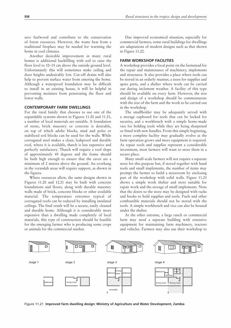
contempoRaRy FaRm dwellIngSFor the rural family that chooses to use one of the expandable systems shown in Figures 11.20 and 11.21, a number of local materials are suitable. A foundation of stone, brick masonry or concrete is desirable, on top of which adobe blocks, mud and poles or stabilized soil blocks can be used for the walls. While corrugated steel makes a clean, leakproof and durable roof, where it is available, thatch is less expensive and perfectly satisfactory. Thatch will require a roof slope of approximately 45 degrees and the frame should be built high enough to ensure that the eaves are a minimum of 2 metres above the ground. An overhang in the verandah areas will require support, as shown in the figures.
Where resources allow, the same designs shown in Figures 11.20 and 12.21 may be built with concrete foundations and floors, along with durable masonry walls made of brick, concrete blocks or other available material. The temperature extremes typical of corrugated roofs can be reduced by installing insulated ceilings. The final result will be a secure, easily cleaned and durable home. Although it is considerably more expensive than a dwelling made completely of local materials, this type of construction should be feasible for the emerging farmer who is producing some crops or animals for the commercial market.
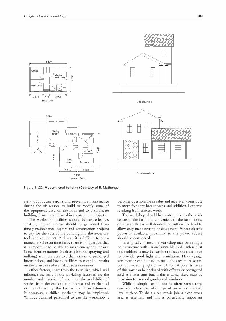
Due improved economical situation, especially for commercial farmers, some rural buildings for dwellings are adaptations of modern designs such as that shown in Figure 11.22.
FaRm woRkShop FacIlItIeSA workshop provides a focal point on the farmstead for the repair and maintenance of machinery, implements and structures. It also provides a place where tools can be stored in an orderly manner, a store for supplies and spare parts, and a shelter where work can be carried out during inclement weather. A facility of this type should be available on every farm. However, the size and design of a workshop should be commensurate with the size of the farm and the work to be carried out in the workshop.
The smallholder may be adequately served with a storage cupboard for tools that can be locked for security, and a workbench with a simple home-made vice for holding tools while they are being sharpened or fitted with new handles. From this simple beginning, a more complete facility may gradually evolve as the farm operation grows and more equipment is required. As repair tools and supplies represent a considerable investment, most farmers will want to store them in a secure place.
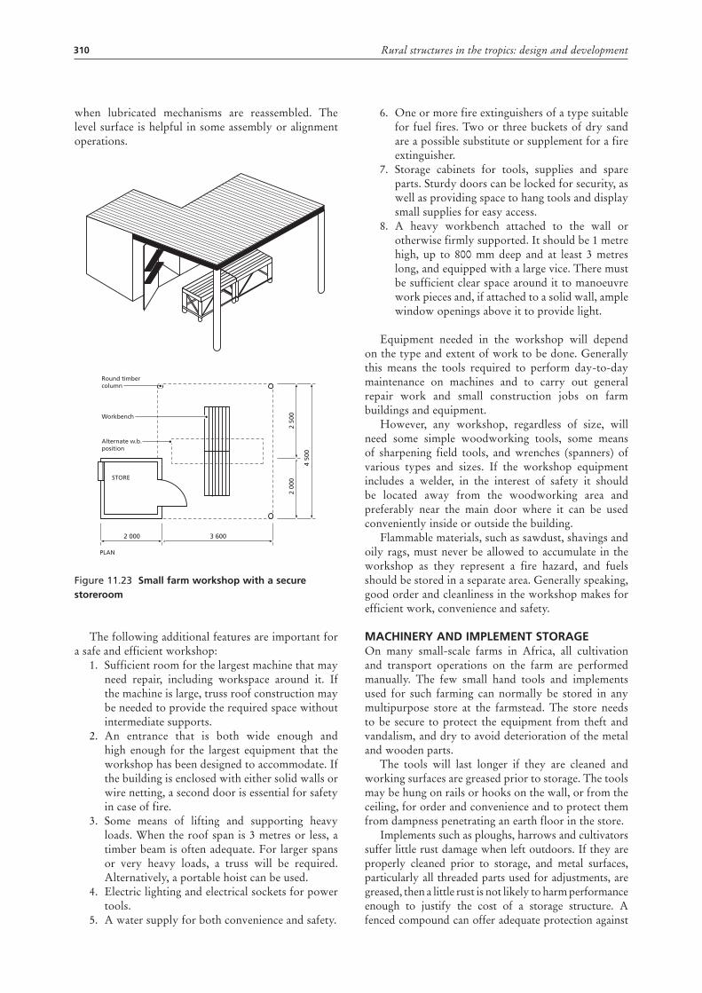
Many small-scale farmers will not require a separate store for this purpose but, if stored together with hand tools and small implements, the number of items may prompt the farmer to build a storeroom by enclosing part of the workshop with solid walls. Figure 11.23 shows a simple work shelter and store suitable for repair work and the storage of small implements. Note that the doors to the store may be designed with racks and hooks to hold supplies and tools. Fuels and other combustible materials should not be stored with the tools. A simple workbench and vice can also be housed under the shelter.
At the other extreme, a large ranch or commercial farm may need a separate building with extensive equipment for maintaining farm machinery, tractors and vehicles. Farmers may also use their workshop to
Figure 11.21 Improved farm dwelling design: ministry of agriculture and water development, Zambia
stage 1
bedroom living room
verandah
bedroom bedroombedroom
kitchen
showertoilet
dining roomliving room
kitchen
stage 2 stage 3 stage 4
309Chapter 11 – Rural buildings
carry out routine repairs and preventive maintenance during the off-season, to build or modify some of the equipment used on the farm and to prefabricate building elements to be used in construction projects.
The workshop facilities should be cost-effective. That is, enough savings should be generated from timely maintenance, repairs and construction projects to pay for the cost of the building and the necessary tools and equipment. Although it is difficult to put a monetary value on timeliness, there is no question that it is important to be able to make emergency repairs. Some farm operations (such as planting, spraying and milking) are more sensitive than others to prolonged interruptions, and having facilities to complete repairs on the farm can reduce delays to a minimum.
Other factors, apart from the farm size, which will influence the scale of the workshop facilities, are the number and diversity of machines, the availability of service from dealers, and the interest and mechanical skill exhibited by the farmer and farm labourers. If necessary, a skilled mechanic may be employed. Without qualified personnel to use the workshop it
becomes questionable in value and may even contribute to more frequent breakdowns and additional expense resulting from careless work.
The workshop should be located close to the work centre of the farm and convenient to the farm home, on ground that is well drained and sufficiently level to allow easy manoeuvring of equipment. Where electric power is available, proximity to the power source should be considered.
In tropical climates, the workshop may be a simple pole structure with a non-flammable roof. Unless dust is a problem, it may be feasible to leave the sides open to provide good light and ventilation. Heavy-gauge wire netting can be used to make the area more secure without reducing light or ventilation. A pole structure of this sort can be enclosed with offcuts or corrugated steel at a later time but, if this is done, there must be provision for several good-sized windows.
While a simple earth floor is often satisfactory, concrete offers the advantage of an easily cleaned, level surface. To do a clean repair job, a clean work area is essential, and this is particularly important
Figure 11.22 modern rural building (courtesy of R. mathenge)
5 74
0
8 320
8 320
Office
Bedroom
Masterbedroom
WcLaundry
2 939 3 905
4 118
4 62
3
hcro
p raC
7 62
0
Sittingroom Kitchen
Dining room Bedroom
Bedroom
W.C.
7 835Ground floor
Front elevation3 568
1 476
First floor Side elevation
310 Rural structures in the tropics: design and development
when lubricated mechanisms are reassembled. The level surface is helpful in some assembly or alignment operations.
Figure 11.23 Small farm workshop with a secure storeroom
The following additional features are important for a safe and efficient workshop:
1. Sufficient room for the largest machine that may need repair, including workspace around it. If the machine is large, truss roof construction may be needed to provide the required space without intermediate supports.
2. An entrance that is both wide enough and high enough for the largest equipment that the workshop has been designed to accommodate. If the building is enclosed with either solid walls or wire netting, a second door is essential for safety in case of fire.
3. Some means of lifting and supporting heavy loads. When the roof span is 3 metres or less, a timber beam is often adequate. For larger spans or very heavy loads, a truss will be required. Alternatively, a portable hoist can be used.
4. Electric lighting and electrical sockets for power tools.
5. A water supply for both convenience and safety.
2 50
02
000
4 50
0
3 6002 000
PLAN
STORE
Alternate w.b.position
Round timbercolumn
Workbench
6. One or more fire extinguishers of a type suitable for fuel fires. Two or three buckets of dry sand are a possible substitute or supplement for a fire extinguisher.
7. Storage cabinets for tools, supplies and spare parts. Sturdy doors can be locked for security, as well as providing space to hang tools and display small supplies for easy access.
8. A heavy workbench attached to the wall or otherwise firmly supported. It should be 1 metre high, up to 800 mm deep and at least 3 metres long, and equipped with a large vice. There must be sufficient clear space around it to manoeuvre work pieces and, if attached to a solid wall, ample window openings above it to provide light.
Equipment needed in the workshop will depend on the type and extent of work to be done. Generally this means the tools required to perform day-to-day maintenance on machines and to carry out general repair work and small construction jobs on farm buildings and equipment.
However, any workshop, regardless of size, will need some simple woodworking tools, some means of sharpening field tools, and wrenches (spanners) of various types and sizes. If the workshop equipment includes a welder, in the interest of safety it should be located away from the woodworking area and preferably near the main door where it can be used conveniently inside or outside the building.
Flammable materials, such as sawdust, shavings and oily rags, must never be allowed to accumulate in the workshop as they represent a fire hazard, and fuels should be stored in a separate area. Generally speaking, good order and cleanliness in the workshop makes for efficient work, convenience and safety.
machIneRy and Implement StoRageOn many small-scale farms in Africa, all cultivation and transport operations on the farm are performed manually. The few small hand tools and implements used for such farming can normally be stored in any multipurpose store at the farmstead. The store needs to be secure to protect the equipment from theft and vandalism, and dry to avoid deterioration of the metal and wooden parts.
The tools will last longer if they are cleaned and working surfaces are greased prior to storage. The tools may be hung on rails or hooks on the wall, or from the ceiling, for order and convenience and to protect them from dampness penetrating an earth floor in the store.
Implements such as ploughs, harrows and cultivators suffer little rust damage when left outdoors. If they are properly cleaned prior to storage, and metal surfaces, particularly all threaded parts used for adjustments, are greased, then a little rust is not likely to harm performance enough to justify the cost of a storage structure. A fenced compound can offer adequate protection against
311Chapter 11 – Rural buildings
theft during storage. Although implements containing wooden parts are more susceptible to decay, these parts can usually be replaced at low cost.
Tractors and other complex machines will function better when needed if they have been stored under cover and given a complete off-season check-up. An adequate storage structure for these machines is likely to be economically justifiable.
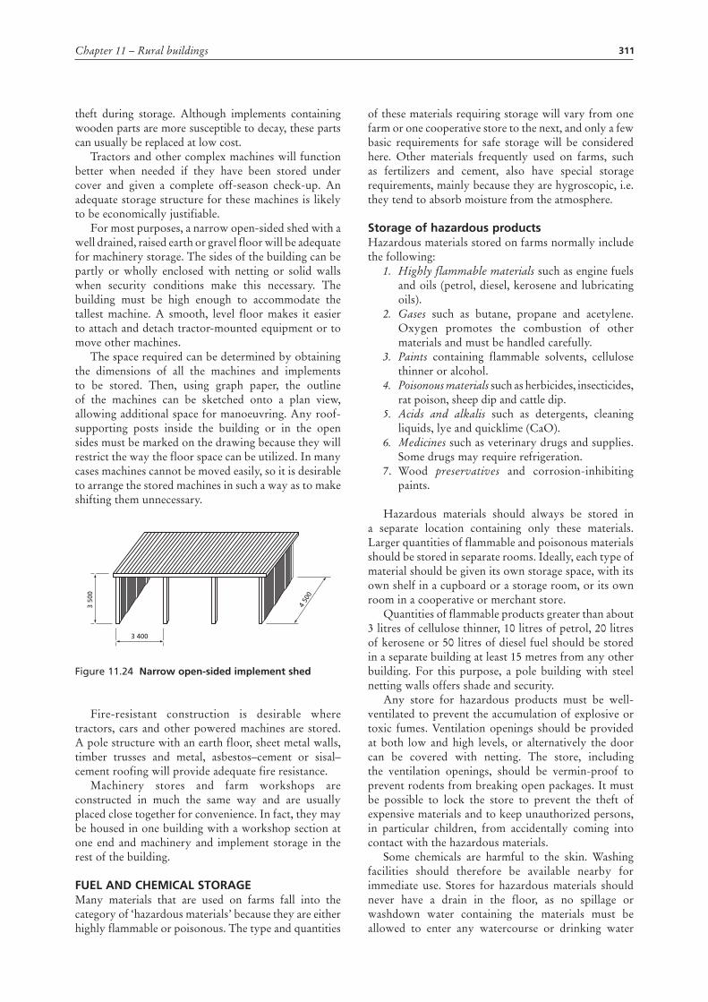
For most purposes, a narrow open-sided shed with a well drained, raised earth or gravel floor will be adequate for machinery storage. The sides of the building can be partly or wholly enclosed with netting or solid walls when security conditions make this necessary. The building must be high enough to accommodate the tallest machine. A smooth, level floor makes it easier to attach and detach tractor-mounted equipment or to move other machines.
The space required can be determined by obtaining the dimensions of all the machines and implements to be stored. Then, using graph paper, the outline of the machines can be sketched onto a plan view, allowing additional space for manoeuvring. Any roof-supporting posts inside the building or in the open sides must be marked on the drawing because they will restrict the way the floor space can be utilized. In many cases machines cannot be moved easily, so it is desirable to arrange the stored machines in such a way as to make shifting them unnecessary.
Figure 11.24 narrow open-sided implement shed
Fire-resistant construction is desirable where tractors, cars and other powered machines are stored. A pole structure with an earth floor, sheet metal walls, timber trusses and metal, asbestos–cement or sisal–cement roofing will provide adequate fire resistance.
Machinery stores and farm workshops are constructed in much the same way and are usually placed close together for convenience. In fact, they may be housed in one building with a workshop section at one end and machinery and implement storage in the rest of the building.
Fuel and chemIcal StoRageMany materials that are used on farms fall into the category of ‘hazardous materials’ because they are either highly flammable or poisonous. The type and quantities
3 400
3 50
0
4 50
0
of these materials requiring storage will vary from one farm or one cooperative store to the next, and only a few basic requirements for safe storage will be considered here. Other materials frequently used on farms, such as fertilizers and cement, also have special storage requirements, mainly because they are hygroscopic, i.e. they tend to absorb moisture from the atmosphere.
Storage of hazardous productsHazardous materials stored on farms normally include the following:
1. Highly flammable materials such as engine fuels and oils (petrol, diesel, kerosene and lubricating oils).
2. Gases such as butane, propane and acetylene. Oxygen promotes the combustion of other materials and must be handled carefully.
3. Paints containing flammable solvents, cellulose thinner or alcohol.
4. Poisonous materials such as herbicides, insecticides, rat poison, sheep dip and cattle dip.
5. Acids and alkalis such as detergents, cleaning liquids, lye and quicklime (CaO).
6. Medicines such as veterinary drugs and supplies. Some drugs may require refrigeration.
7. Wood preservatives and corrosion-inhibiting paints.
Hazardous materials should always be stored in a separate location containing only these materials. Larger quantities of flammable and poisonous materials should be stored in separate rooms. Ideally, each type of material should be given its own storage space, with its own shelf in a cupboard or a storage room, or its own room in a cooperative or merchant store.
Quantities of flammable products greater than about 3 litres of cellulose thinner, 10 litres of petrol, 20 litres of kerosene or 50 litres of diesel fuel should be stored in a separate building at least 15 metres from any other building. For this purpose, a pole building with steel netting walls offers shade and security.
Any store for hazardous products must be well-ventilated to prevent the accumulation of explosive or toxic fumes. Ventilation openings should be provided at both low and high levels, or alternatively the door can be covered with netting. The store, including the ventilation openings, should be vermin-proof to prevent rodents from breaking open packages. It must be possible to lock the store to prevent the theft of expensive materials and to keep unauthorized persons, in particular children, from accidentally coming into contact with the hazardous materials.
Some chemicals are harmful to the skin. Washing facilities should therefore be available nearby for immediate use. Stores for hazardous materials should never have a drain in the floor, as no spillage or washdown water containing the materials must be allowed to enter any watercourse or drinking water
312 Rural structures in the tropics: design and development
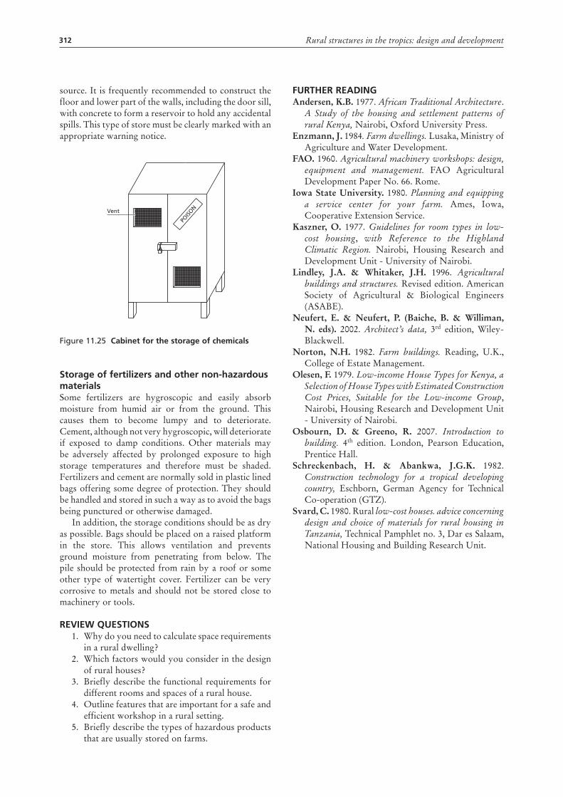
source. It is frequently recommended to construct the floor and lower part of the walls, including the door sill, with concrete to form a reservoir to hold any accidental spills. This type of store must be clearly marked with an appropriate warning notice.
Figure 11.25 cabinet for the storage of chemicals
Storage of fertilizers and other non-hazardous materialsSome fertilizers are hygroscopic and easily absorb moisture from humid air or from the ground. This causes them to become lumpy and to deteriorate. Cement, although not very hygroscopic, will deteriorate if exposed to damp conditions. Other materials may be adversely affected by prolonged exposure to high storage temperatures and therefore must be shaded. Fertilizers and cement are normally sold in plastic lined bags offering some degree of protection. They should be handled and stored in such a way as to avoid the bags being punctured or otherwise damaged.
In addition, the storage conditions should be as dry as possible. Bags should be placed on a raised platform in the store. This allows ventilation and prevents ground moisture from penetrating from below. The pile should be protected from rain by a roof or some other type of watertight cover. Fertilizer can be very corrosive to metals and should not be stored close to machinery or tools.
ReVIew queStIonS1. Why do you need to calculate space requirements
in a rural dwelling?2. Which factors would you consider in the design
of rural houses?3. Briefly describe the functional requirements for
different rooms and spaces of a rural house.4. Outline features that are important for a safe and
efficient workshop in a rural setting.5. Briefly describe the types of hazardous products
that are usually stored on farms.
POISO
NVent
FuRtheR ReadIngAndersen, K.B. 1977. African Traditional Architecture.
A Study of the housing and settlement patterns of rural Kenya, Nairobi, Oxford University Press.
Enzmann, J. 1984. Farm dwellings. Lusaka, Ministry of Agriculture and Water Development.
FAO. 1960. Agricultural machinery workshops: design, equipment and management. FAO Agricultural Development Paper No. 66. Rome.
Iowa State University. 1980. Planning and equipping a service center for your farm. Ames, Iowa, Cooperative Extension Service.
Kaszner, O. 1977. Guidelines for room types in low-cost housing, with Reference to the Highland Climatic Region. Nairobi, Housing Research and Development Unit - University of Nairobi.
Lindley, J.A. & Whitaker, J.H. 1996. Agricultural buildings and structures. Revised edition. American Society of Agricultural & Biological Engineers (ASABE).
Neufert, E. & Neufert, P. (Baiche, B. & Williman, N. eds). 2002. Architect’s data, 3rd edition, Wiley-Blackwell.
Norton, N.H. 1982. Farm buildings. Reading, U.K., College of Estate Management.
Olesen, F. 1979. Low-income House Types for Kenya, a Selection of House Types with Estimated Construction Cost Prices, Suitable for the Low-income Group, Nairobi, Housing Research and Development Unit - University of Nairobi.
Osbourn, D. & Greeno, R. 2007. Introduction to building. 4th edition. London, Pearson Education, Prentice Hall.
Schreckenbach, H. & Abankwa, J.G.K. 1982. Construction technology for a tropical developing country, Eschborn, German Agency for Technical Co-operation (GTZ).
Svard, C. 1980. Rural low-cost houses. advice concerning design and choice of materials for rural housing in Tanzania, Technical Pamphlet no. 3, Dar es Salaam, National Housing and Building Research Unit.
313
Chapter 12
Fundamentals of heating and cooling
Heat terminologyHeat is a form of energy. The molecules of a body are in constant motion and possess kinetic energy, referred to as heat.
Temperature is the intensity of heat, i.e. the velocity of the molecules. Under the Système Internationale (SI) system, it is measured in degrees celsius (centigrade) or kelvin (absolute).
Ambient temperature is the temperature of the medium surrounding a body, e.g. the air temperature within a building.
Quantity of heat is measured in joules (J). One calorie of heat will raise 1 gram of water 1 kelvin. This equals 4.187 joules.
Sensible heat is the heat that causes a temperature change when there is a heat transfer, e.g. heat moving through the walls of a home causing a temperature rise.
Latent heat is the heat that causes a change in state but no change in temperature, such as heat that is absorbed when ice changes to water, or when boiling water changes to vapour. However, water will evaporate to vapour over a wide range of temperatures. When air moves across the surface of water, some of the air’s sensible heat is converted to latent heat, causing the air temperature to drop. The latent heat of vaporization changes with temperature:
°C kJ/kg 0 2 500 30 2 430 100 2 256
Thermal capacity is the ability of a material to absorb and hold heat. It is measured in J/(kg.K). The thermal capacity of water is 4 187 J/(kg.K) or 4.187 J/(g.K).
Specific heat is the dimensionless ratio between the thermal capacity of a material and that of water. However the actual thermal capacity measured in J/(kg.K) is often listed as specific heat.
Total heat content. Bodies with great mass can store large quantities of heat, even at low temperatures. For instance, thick masonry walls are slow to warm up during the hot daytime and slow to cool down during a cool night. A match has a high temperature and little heat content. A large tank of water may have a low temperature but still possess a large content of heat.
Heat transFerBasic to any discussion of insulation and ventilation is an understanding of the way heat is transferred. Heat is transferred whenever there is a temperature difference, by conduction, convection, radiation or a combination of these methods.
ConductionIn conduction, heat energy is passed from molecule to molecule in a material. For heat to be conducted, it is essential to have physical contact between particles and a temperature difference. Thermal conductivity is a measure of how easily heat is passed from particle to particle. The rate of heat flow depends on the temperature difference and the thermal conductivity of the material. The rate of heat conduction through a substance is given by Fourier’s equation:
where:q = heat conduction rate (W)k = thermal conductivity of material (W/m2.°C)A = cross-sectional area normal to the direction of heat flow (m2)∆T = temperature gradient (°C)∆L = thickness of the material conducting heat (m).
ConvectionHeat is transferred by convection when a heated liquid or gas (often air) actually moves from one place to another, carrying its heat with it. The rate of heat flow depends on the temperature of the moving fluid and the rate of flow. Convection transfer can occur in any liquid or gas. The rate of heat transfer by convection is:
qc = h A(Ts – T∞)
where:qc = convective heat transfer rate (W)h = heat transfer coefficient (W/m2.°C)A = surface area (m2)Ts = surface temperature (°C)T∞ = free stream fluid temperature (°C).
∆∆
−=LT
Akq
314 Rural structures in the tropics: design and development
radiationHeat energy can be transferred in the form of electromagnetic waves. These waves emanate from a hot body and can travel freely only through completely transparent media. Heat cannot move by radiation through opaque materials, but instead is partially absorbed by and reflected from their surfaces. The atmosphere, glass and translucent materials pass a substantial amount of radiant energy, at the same time absorbing some and reflecting some. Although all surfaces radiate energy, there will always be a net transfer from the warmer to the cooler of two surfaces facing each other, which is calculated as:
qr = Fe Fa A σ (T14 – T2
4)
where:qr = radiative heat transfer rate (W)Fe = radiation factor allowing for part of the radiation being re-radiated to the body it came from (dimensionless)Fa = a geometric factor allowing for size, slope, and orientation of the two bodies (dimensionless)A = surface area of the smaller of the two bodies (m2)σ = Stefan–Boltzmann constant (5.67 × 10⁻⁸ W/(m2.K4))T = absolute temperatures of the radiating bodies (K).
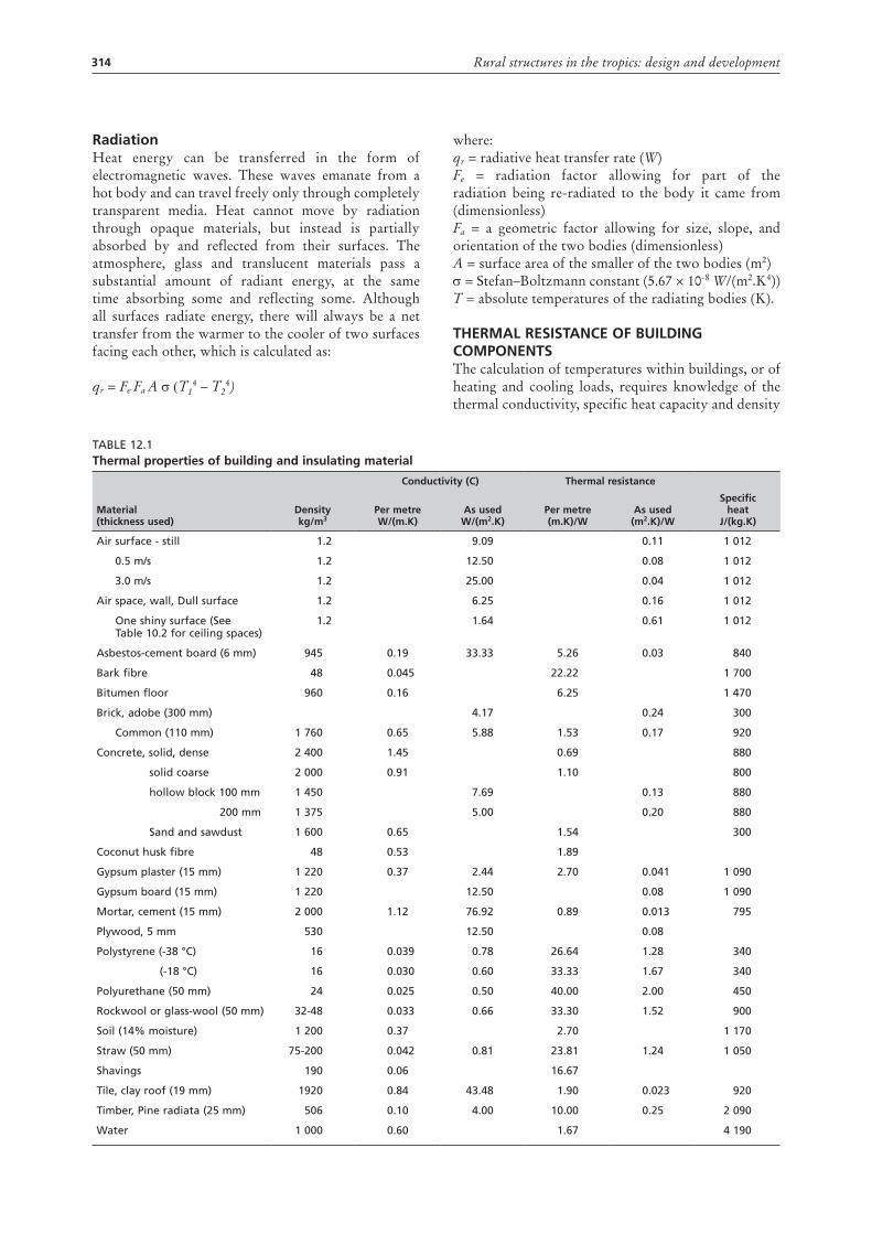
tHermal resistanCe oF building ComponentsThe calculation of temperatures within buildings, or of heating and cooling loads, requires knowledge of the thermal conductivity, specific heat capacity and density
Table 12.1thermal properties of building and insulating material
material (thickness used)
density kg/m3
Conductivity (C) thermal resistance
specific heat
J/(kg.K)per metre W/(m.K)
as used W/(m2.K)
per metre (m.K)/W
as used (m2.K)/W
air surface - still 1.2 9.09 0.11 1 012
0.5 m/s 1.2 12.50 0.08 1 012
3.0 m/s 1.2 25.00 0.04 1 012
air space, wall, Dull surface 1.2 6.25 0.16 1 012
One shiny surface (See Table 10.2 for ceiling spaces)
1.2 1.64 0.61 1 012
asbestos-cement board (6 mm) 945 0.19 33.33 5.26 0.03 840
bark fibre 48 0.045 22.22 1 700
bitumen floor 960 0.16 6.25 1 470
brick, adobe (300 mm) 4.17 0.24 300
Common (110 mm) 1 760 0.65 5.88 1.53 0.17 920
Concrete, solid, dense 2 400 1.45 0.69 880
solid coarse 2 000 0.91 1.10 800
hollow block 100 mm 1 450 7.69 0.13 880
200 mm 1 375 5.00 0.20 880
Sand and sawdust 1 600 0.65 1.54 300
Coconut husk fibre 48 0.53 1.89
Gypsum plaster (15 mm) 1 220 0.37 2.44 2.70 0.041 1 090
Gypsum board (15 mm) 1 220 12.50 0.08 1 090
Mortar, cement (15 mm) 2 000 1.12 76.92 0.89 0.013 795
Plywood, 5 mm 530 12.50 0.08
Polystyrene (-38 °C) 16 0.039 0.78 26.64 1.28 340
(-18 °C) 16 0.030 0.60 33.33 1.67 340
Polyurethane (50 mm) 24 0.025 0.50 40.00 2.00 450
Rockwool or glass-wool (50 mm) 32-48 0.033 0.66 33.30 1.52 900
Soil (14% moisture) 1 200 0.37 2.70 1 170
Straw (50 mm) 75-200 0.042 0.81 23.81 1.24 1 050
Shavings 190 0.06 16.67
Tile, clay roof (19 mm) 1920 0.84 43.48 1.90 0.023 920
Timber, Pine radiata (25 mm) 506 0.10 4.00 10.00 0.25 2 090
Water 1 000 0.60 1.67 4 190
315Chapter 12 – Fundamentals of heating and cooling
of the construction materials. The thermal resistances of air films adjacent to surfaces, and of air spaces, are also required and, as the latter are dependent on the emittances of surfaces, data on these parameters are also needed.
Table 12.1 contains a list of materials with their thermal properties. The thermal resistance, which is the quotient of thickness and thermal conductivity, has been given and, where appropriate, for the material thicknesses most commonly used. As in most cases there is a linear relationship between thickness and thermal resistance, other values are readily calculated.
This may not be the case for granular materials when the grain size becomes comparable with the thickness and therefore caution should be shown when assigning resistance values to such materials.
insulating materialsThe choice of an insulating material will depend on the application, availability and cost. Loose granular materials work best when installed above a ceiling or poured into existing wall cavities. Batting or blanket materials are easiest to install as walls are constructed. Rigid insulating boards may be placed under concrete floors or cemented to masonry walls.
Reflective surfaces, such as aluminium foil or paint, are most effective when exposed and not in contact with other materials. They are also more effective in preventing the downward flow of heat and in relatively high-temperature applications.
Local natural materials, such as straw, shavings or coffee hulls, while not as resistant to heat flow as commercial insulation, may be the material of choice because of their availability and low cost. A greater thickness will be required when using natural materials, but they may not be as fire- and vermin-resistant.
selecting insulationThe following factors should be considered when selecting insulation material:
• R-value: the higher the R-value, the better the insulation.
• Fire resistance: some materials may require a fire-resistant liner to prevent rapid flame spread.
• Cost: preparation, installation, protection and purchase price all increase the cost.
• Part of the building to be insulated: roofs and walls have limitations on insulation thickness, while ceilings require thicker insulation material.
• Ease of installation: some materials are time-consuming and labour-intensive to install.
• Exposure to animals: consider whether the animals will come into contact with the insulation – if so, a protective covering may be necessary.
surface resistancesThe values of surface resistances are influenced by several factors, the most important of which is the rate
of air movement over the surface. Values for 3 metres per second and 0.5 metres per second of air movement and for still air are shown in Table 12.1.
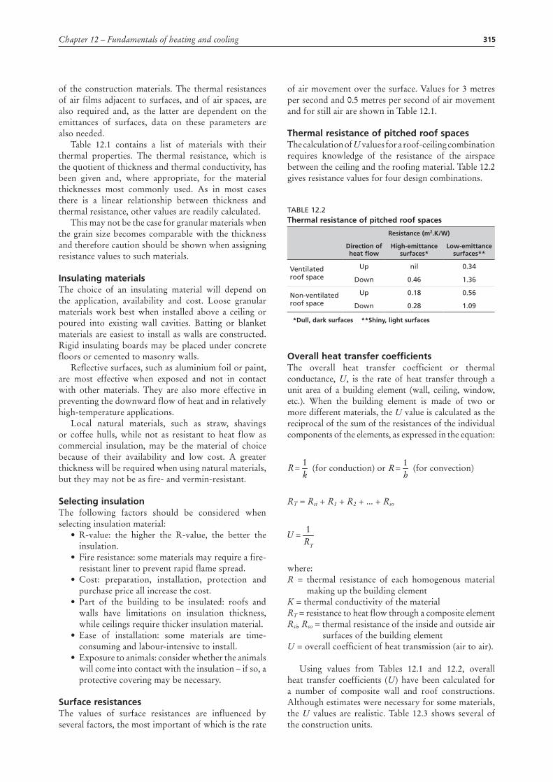
thermal resistance of pitched roof spacesThe calculation of U values for a roof-ceiling combination requires knowledge of the resistance of the airspace between the ceiling and the roofing material. Table 12.2 gives resistance values for four design combinations.
Table 12.2thermal resistance of pitched roof spaces
resistance (m2.K/W)
direction of heat flow
High-emittance surfaces*
low-emittance surfaces**
Ventilated roof space
Up nil 0.34
Down 0.46 1.36
Non-ventilated roof space
Up 0.18 0.56
Down 0.28 1.09
*dull, dark surfaces **shiny, light surfaces
overall heat transfer coefficientsThe overall heat transfer coefficient or thermal conductance, U, is the rate of heat transfer through a unit area of a building element (wall, ceiling, window, etc.). When the building element is made of two or more different materials, the U value is calculated as the reciprocal of the sum of the resistances of the individual components of the elements, as expressed in the equation:
kR
1=
hR
1=
RT
U1
=
(for conduction) or k
R1
=h
R1
=
RT
U1
=
(for convection)
RT = Rsi + R1 + R2 + ... + Rsok
R1
=h
R1
=
RT
U1
=
where:R = thermal resistance of each homogenous material making up the building elementK = thermal conductivity of the materialRT = resistance to heat flow through a composite elementRsi, Rso = thermal resistance of the inside and outside air surfaces of the building elementU = overall coefficient of heat transmission (air to air).
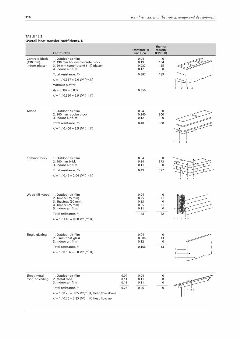
Using values from Tables 12.1 and 12.2, overall heat transfer coefficients (U) have been calculated for a number of composite wall and roof constructions. Although estimates were necessary for some materials, the U values are realistic. Table 12.3 shows several of the construction units.
316 Rural structures in the tropics: design and development
Table 12.3overall heat transfer coefficients, u
Constructionresistance, r
(m2.K)/W
thermal capacity (kJ/m2.K)
Concrete block (190 mm) Indoor plaster
1. Outdoor air film 2. 190 mm hollow concrete block 3. 20 mm cement:sand (1:4) plaster 4. Indoor air film
Total resistance, RT
U = 1 / 0.387 = 2.6 W/ (m2.K)
Without plaster
RT = 0.387 – 0.037
U = 1 / 0.350 = 2.9 W/ (m2.K)
0.040.190.0370.12
0.387
0.350
0164
250
189
1 2 3 4
adobe 1. Outdoor air film 2. 300 mm adobe block 3. Indoor air film
Total resistance, RT
U = 1 / 0.400 = 2.5 W/ (m2.K)
0.040.2400.12
0.40
0300
0
300
1 2 3
Common brick 1. Outdoor air film 2. 200 mm brick 3. Indoor air film
Total resistance, RT
U = 1 / 0.49 = 2.04 W/ (m2.K)
0.040.340.11
0.49
0372
0
372
1 2 3
Wood-fill–wood 1. Outdoor air film 2. Timber (25 mm) 3. Shavings (50 mm) 4. Timber (25 mm) 5. Indoor air film
Total resistance, RT
U = 1 / 1.48 = 0.68 W/ (m2.K)
0.040.250.830.250.11
1.48
021
021
0
42
1 2 3 4 5
Single glazing 1. Outdoor air film 2. 6 mm float glass 3. Indoor air film
Total resistance, RT
U = 1 / 0.166 = 6.0 W/ (m2.K)
0.040.0060.12
0.166
013
0
131
2
3
Sheet metal roof, no ceiling
1. Outdoor air film 2. Metal roof 3. Indoor air film
Total resistance, RT
U = 1 / 0.26 = 3.85 W/(m2.K) heat flow down
U = 1 / 0.26 = 3.85 W/(m2.K) heat flow up
0.04 0.11 0.11
0.26
0.040.110.11
0.26
000
01 2 3
317Chapter 12 – Fundamentals of heating and cooling
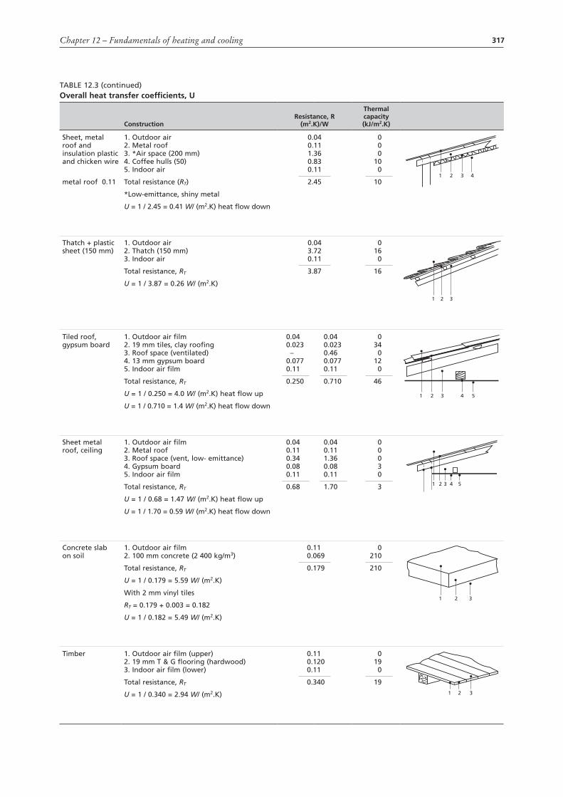
Table 12.3 (continued)overall heat transfer coefficients, u
Constructionresistance, r
(m2.K)/W
thermal capacity (kJ/m2.K)
Sheet, metal roof and insulation plastic and chicken wire
metal roof 0.11
1. Outdoor air 2. Metal roof 3. *air space (200 mm) 4. Coffee hulls (50) 5. Indoor air
Total resistance (RT)
*low-emittance, shiny metal
U = 1 / 2.45 = 0.41 W/ (m2.K) heat flow down
0.040.111.360.830.11
2.45
000
100
101 2 3 4
Thatch + plastic sheet (150 mm)
1. Outdoor air 2. Thatch (150 mm) 3. Indoor air
Total resistance, RT
U = 1 / 3.87 = 0.26 W/ (m2.K)
0.043.720.11
3.87
016
0
16
1 2 3
Tiled roof, gypsum board
1. Outdoor air film 2. 19 mm tiles, clay roofing 3. Roof space (ventilated) 4. 13 mm gypsum board 5. Indoor air film
Total resistance, RT
U = 1 / 0.250 = 4.0 W/ (m2.K) heat flow up
U = 1 / 0.710 = 1.4 W/ (m2.K) heat flow down
0.040.023
–0.0770.11
0.250
0.040.0230.460.0770.11
0.710
034
012
0
46
1 2 3 4 5
Sheet metal roof, ceiling
1. Outdoor air film 2. Metal roof 3. Roof space (vent, low- emittance) 4. Gypsum board 5. Indoor air film
Total resistance, RT
U = 1 / 0.68 = 1.47 W/ (m2.K) heat flow up
U = 1 / 1.70 = 0.59 W/ (m2.K) heat flow down
0.040.110.340.080.11
0.68
0.040.111.360.080.11
1.70
00030
3 1 2 3 4 5
Concrete slab on soil
1. Outdoor air film 2. 100 mm concrete (2 400 kg/m3)
Total resistance, RT
U = 1 / 0.179 = 5.59 W/ (m2.K)
With 2 mm vinyl tiles
RT = 0.179 + 0.003 = 0.182
U = 1 / 0.182 = 5.49 W/ (m2.K)
0.110.069
0.179
0210
210
1 2 3
Timber 1. Outdoor air film (upper) 2. 19 mm T & G flooring (hardwood) 3. Indoor air film (lower)
Total resistance, RT
U = 1 / 0.340 = 2.94 W/ (m2.K)
0.110.1200.11
0.340
019
0
191 2 3
318 Rural structures in the tropics: design and development
The effect on U values and overall heat transfer of timber and metal frames in walls is in the order of 5 percent and may usually be ignored. However, local effects may be observed. The more rapid heat loss through the framing of a heavily insulated wall may lower the wall temperature adjacent to the framing locations to the point where it causes condensation.
rate oF overall Heat loss or gain From a buildingOnce the U values have been calculated for each element of the building (walls, ceiling, windows, doors, etc.), the area of each element is determined and design temperatures for inside and outside are chosen. It follows that, for each building element:
Q=A × U × ∆T
where:Q = total heat transfer rate through an element (W)A = area of the building element (m²)U = coefficient of heat transfer for the element (W/m2.K)∆T = temperature differential across the element (K).
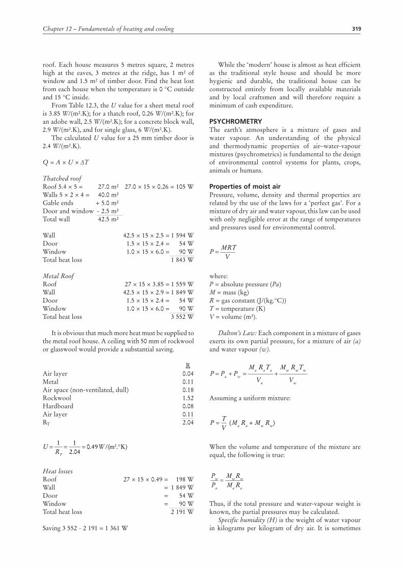
For the building as a whole, the total heat exchange rate will equal the sum of the Q values. Total heat transfer in joules for a given period may be found by multiplying kilowatts by 3.6 Megajoules times the number of hours. Figure 12.1 provides some rough approximations of maximum and minimum temperatures for design purposes. Temperature data for the immediate area in which the building will be constructed will provide the most accurate results.
Figure 12.1a Highest mean monthly maximum temperature (°C)
30
30
3040
40
30
30
200 800
km
1 600
3030
30
30
30
30
40
40
30
30
45
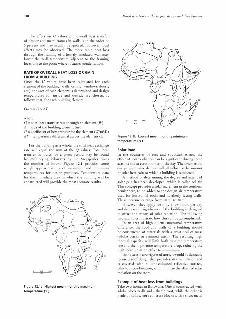
Figure 12.1b lowest mean monthly minimum temperature (°C)
solar loadIn the countries of east and southeast Africa, the effect of solar radiation can be significant during some seasons and at certain times of the day. The orientation, design, and materials used will all influence the amount of solar heat gain to which a building is subjected.
A method of determining the degree and extent of solar gain has been developed, which is called sol-air. This concept provides a solar increment in the southern hemisphere, to be added to the design air temperature used for horizontal roofs and northerly facing walls. These increments range from 10 °C to 30 °C.
However, they apply for only a few hours per day and decrease in significance if the building is designed to offset the effects of solar radiation. The following two examples illustrate how this can be accomplished.
In an area of high diurnal-nocturnal temperature difference, the roof and walls of a building should be constructed of materials with a great deal of mass (adobe bricks or rammed earth). The resulting high thermal capacity will limit both daytime temperature rise and the night-time temperature drop, reducing the high solar radiation effect to a minimum.
In the case of a refrigerated store, it would be desirable to use a roof design that provides attic ventilation and is covered with a light-coloured reflective surface, which, in combination, will minimize the effect of solar radiation on the store.
example of heat loss from buildings Take two homes in Botswana. One is constructed with adobe block walls and a thatch roof, while the other is made of hollow core concrete blocks with a sheet metal
20
15
5 5
5
15
20
20
15
20
15
15
20
2020
15
15
15
0 800
km
1 600
319Chapter 12 – Fundamentals of heating and cooling
roof. Each house measures 5 metres square, 2 metres high at the eaves, 3 metres at the ridge, has 1 m² of window and 1.5 m² of timber door. Find the heat lost from each house when the temperature is 0 °C outside and 15 °C inside.
From Table 12.3, the U value for a sheet metal roof is 3.85 W/(m².K); for a thatch roof, 0.26 W/(m².K); for an adobe wall, 2.5 W/(m².K); for a concrete block wall, 2.9 W/(m².K), and for single glass, 6 W/(m².K).
The calculated U value for a 25 mm timber door is 2.4 W/(m².K).
Q = A × U × ∆T
Thatched roofRoof 5.4 × 5 = 27.0 m² 27.0 × 15 × 0.26 = 105 WWalls 5 × 2 × 4 = 40.0 m²Gable ends + 5.0 m²Door and window - 2.5 m²Total wall 42.5 m²
Wall 42.5 × 15 × 2.5 = 1 594 WDoor 1.5 × 15 × 2.4 = 54 WWindow 1.0 × 15 × 6.0 = 90 WTotal heat loss 1 843 W
Metal RoofRoof 27 × 15 × 3.85 = 1 559 WWall 42.5 × 15 × 2.9 = 1 849 WDoor 1.5 × 15 × 2.4 = 54 WWindow 1.0 × 15 × 6.0 = 90 WTotal heat loss 3 552 W
It is obvious that much more heat must be supplied to the metal roof house. A ceiling with 50 mm of rockwool or glasswool would provide a substantial saving.
RAir layer 0.04Metal 0.11Air space (non-ventilated, dull) 0.18Rockwool 1.52Hardboard 0.08Air layer 0.11RT 2.04
Heat losses Roof 27 × 15 × 0.49 = 198 WWall = 1 849 WDoor = 54 WWindow = 90 WTotal heat loss 2 191 W
Saving 3 552 - 2 191 = 1 361 W
/(49.004.211
m2.°K)WRT
U ===
While the ‘modern’ house is almost as heat efficient as the traditional style house and should be more hygienic and durable, the traditional house can be constructed entirely from locally available materials and by local craftsmen and will therefore require a minimum of cash expenditure.
psyCHrometryThe earth’s atmosphere is a mixture of gases and water vapour. An understanding of the physical and thermodynamic properties of air–water-vapour mixtures (psychrometrics) is fundamental to the design of environmental control systems for plants, crops, animals or humans.
properties of moist airPressure, volume, density and thermal properties are related by the use of the laws for a ‘perfect gas’. For a mixture of dry air and water vapour, this law can be used with only negligible error at the range of temperatures and pressures used for environmental control.
where:P = absolute pressure (Pa)M = mass (kg)R = gas constant (J/(kg.°C))T = temperature (K)V = volume (m³).
Dalton’s Law: Each component in a mixture of gases exerts its own partial pressure, for a mixture of air (a) and water vapour (w).
Assuming a uniform mixture:
When the volume and temperature of the mixture are equal, the following is true:
Thus, if the total pressure and water-vapour weight is known, the partial pressures may be calculated.
Specific humidity (H) is the weight of water vapour in kilograms per kilogram of dry air. It is sometimes
VMRT
P =
Vw
TwRwMw
Va
TaRaMaPwPaP +=+=
(Ma Ra + Mw Rw)VT
P =
RaMa
RwMw
Pa
Pw =
RwPw)(PRaPw
RwPa
RaPw
TRa
VPa
TRw
VPw
Ma
MwH−
=====
VMRT
P =
Vw
TwRwMw
Va
TaRaMaPwPaP +=+=
(Ma Ra + Mw Rw)VT
P =
RaMa
RwMw
Pa
Pw =
RwPw)(PRaPw
RwPa
RaPw
TRa
VPa
TRw
VPw
Ma
MwH−
=====
VMRT
P =
Vw
TwRwMw
Va
TaRaMaPwPaP +=+=
(Ma Ra + Mw Rw)VT
P =
RaMa
RwMw
Pa
Pw =
RwPw)(PRaPw
RwPa
RaPw
TRa
VPa
TRw
VPw
Ma
MwH−
=====
VMRT
P =
Vw
TwRwMw
Va
TaRaMaPwPaP +=+=
(Ma Ra + Mw Rw)VT
P =
RaMa
RwMw
Pa
Pw =
RwPw)(PRaPw
RwPa
RaPw
TRa
VPa
TRw
VPw
Ma
MwH−
=====
320 Rural structures in the tropics: design and development
called absolute humidity or humidity ratio. The base of 1 kilogram of dry air is constant for any change of condition, making calculations easier.
Relative humidity (RH) is the ratio of the actual water-vapour pressure (Pw) to the vapour pressure of saturated air at the same temperature (Pwsat).
The vapour pressure at saturation (Pwsat) is given in steam tables for different dry-bulb temperatures.
Specific volume is the volume of dry air per mass of dry air.
Humid volume is the volume of an air-moisture mixture per mass of dry air. In ventilation calculations, the volume is in cubic metres of mixture (air + water vapour) per kilogram of dry air. The base of 1 kilogram of dry air is used because the kilogram of dry air entering and leaving the system in a given time will be constant once a steady state flow is established. Humid volume increases as the temperature or water-vapour content increases. The humid volume of air–water-vapour mixtures is given in standard thermodynamic tables, or may be read from a psychrometric chart.
Temperatures: Air–water-vapour mixtures can be described by the dry-bulb temperature, and either the wet-bulb or dew point temperatures:
• dry-bulb temperature is measured with a common thermometer, thermocouple or thermistor
• wet-bulb temperature is the temperature at which water, by evaporating into moist air, can bring the air to saturation adiabatically in a steady-state condition
• dew point temperature is the temperature at which moisture starts to condense from air cooled at constant pressure and specific humidity.
Enthalpy (h) is the heat-energy content of an air–water-vapour mixture. The energy is a combination of both sensible heat (indicated by dry-bulb temperature) and latent heat of vaporization (energy content of the water vapour). Enthalpy scales appear on psychrometric charts expressed as kJ/kg of dry air.
Enthalpy can be calculated from the equation:
h = S × tdb + H × hw
where:S = specific heat of dry air (1 004 kJ/(kg.K))tdb = dry-bulb temperature
VMRT
P =
Vw
TwRwMw
Va
TaRaMaPwPaP +=+=
(Ma Ra + Mw Rw)VT
P =
RaMa
RwMw
Pa
Pw =
RwPw)(PRaPw
RwPa
RaPw
TRa
VPa
TRw
VPw
Ma
MwH−
=====
Pwsat
PwRH 100%=
H = specific humidityhw = enthalpy of water vapour (kJ/kg water vapour).
Thus:
h = 1.004 × tdb + H(2454 + 1858 × tdb) kJ/kg
where:2 454 = latent heat of vaporization (kJ/kg)1 858 = specific heat of water vapour (kJ/(kg.K)).
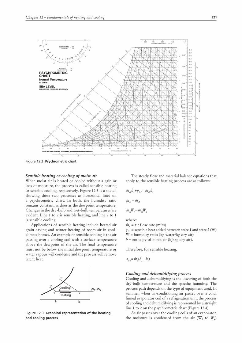
psychrometric chartA psychrometric chart (Figure 12.2 and Appendix V:4-6) is a graphical representation of the thermodynamic properties of moist air. It is useful for solving engineering design problems. Charts for agricultural applications are usually corrected to standard atmospheric pressure of 101.325 kPa. However, charts for other elevations are available. The following properties are shown on a psychrometric chart:
• dry-bulb temperature• wet-bulb temperature• dewpoint temperature• moisture content or specific humidity• enthalpy• relative humidity• specific volume• humid ratio
The intersection of any two property lines establishes a given state, and all other properties can be read from that point. The changes that take place between any two points are of particular use. The vertical lines show dry-bulb temperatures; the curved lines show relative humidity; the slant lines show wet-bulb temperatures and enthalpy; the horizontal lines show dewpoint temperatures and specific humidity; and the steep slant lines show specific and humid volume.
The wet- and dry-bulb temperature for a building area may be read from a psychrometer and then used to establish a point of intersection on the chart. Psychrometers consist of two thermometers mounted close together, one of which has a wick on the bulb that has been moistened with a few drops of distilled water. Air movement is necessary. A sling psychrometer, which is actually swung in the air, is the simplest and least expensive type of psychrometer. However, for locations with restricted space, a motorized psychrometer must be used. The air movement in a ventilation duct is adequate to provide accurate readings from stationary temperature sensors.
air–water-vapour mixture processesConditioning of air–water-vapour mixtures involves heating, cooling, humidifying or dehumidifying, or a combination of these factors.
321Chapter 12 – Fundamentals of heating and cooling
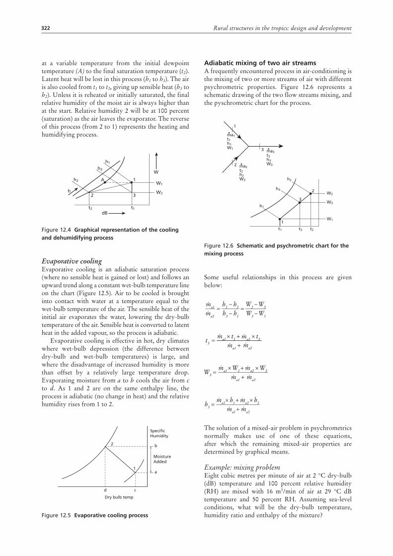
Sensible heating or cooling of moist airWhen moist air is heated or cooled without a gain or loss of moisture, the process is called sensible heating or sensible cooling, respectively. Figure 12.3 is a sketch showing these two processes as horizontal lines on a psychrometric chart. In both, the humidity ratio remains constant, as does as the dewpoint temperature. Changes in the dry-bulb and wet-bulb temperatures are evident. Line 1 to 2 is sensible heating, and line 2 to 1 is sensible cooling.
Applications of sensible heating include heated-air grain drying and winter heating of room air in cool-climate homes. An example of sensible cooling is the air passing over a cooling coil with a surface temperature above the dewpoint of the air. The final temperature must not be below the initial dewpoint temperature or water vapour will condense and the process will remove latent heat.
Figure 12.3 graphical representation of the heating and cooling process
W1=W2
h2
h1
t1 t2
Cooling
1 2Heating
The steady flow and material balance equations that apply to the sensible heating process are as follows:
where:ma = air flow rate (m3/s)
q1-2 = sensible heat added between state 1 and state 2 (W)W = humidity ratio (kg water/kg dry air)h = enthalpy of moist air (kJ/kg dry air).
Therefore, for sensible heating,
Cooling and dehumidifying processCooling and dehumidifying is the lowering of both the dry-bulb temperature and the specific humidity. The process path depends on the type of equipment used. In summer, when air-conditioning air passes over a cold, finned evaporator coil of a refrigeration unit, the process of cooling and dehumidifying is represented by a straight line 1 to 2 on the psychrometric chart (Figure 12.4).
As air passes over the cooling coils of an evaporator, the moisture is condensed from the air (W1 to W2)
q1-2h1ma1
ma1
h2ma2=+
ma2=
W2ma2W1ma1 =
)( h1h2ma −= q1-2
q1-2h1ma1
ma1
h2ma2=+
ma2=
W2ma2W1ma1 =
)( h1h2ma −= q1-2
q1-2h1ma1
ma1
h2ma2=+
ma2=
W2ma2W1ma1 =
)( h1h2ma −= q1-2
q1-2h1ma1
ma1
h2ma2=+
ma2=
W2ma2W1ma1 =
)( h1h2ma −= q1-2
BAROMETRIC PRESSURE: 101.325 kPa
PSYCHROMETRICCHARTNormal TemperatureSI Units
SEA LEVEL
-25 -20 -15 -10 -5 0 5 10 15 20 25 30 35 40 45 50 55
DRY BULB TEMPERATURE - °C
-20 -10 0 10 20 30 40 50 60
70
80
90
100
110
120
130
EN
THA
LPY
- KJ
PE
R K
ILO
GR
AM
OF
DR
Y A
IR
-20
-10
0
10
20
30
40
50
60
70
80
90
100
ENTHALP
Y - KJ P
ER KILO
GRAM OF D
RY AIR
SATURAT
ION TE
MPERATURE - °
C
1.0
2.0
3.0
4.0
5.0
6.0
7.0
8.0
9.0
10.0
11.0
12.0
13.0
14.0
15.0
16.0
17.0
18.0
19.0
20.0
21.0
22.0
23.0
24.0
25.0
26.0
27.0
28.0
29.0
30.0
31.0
32.0
33.0
34.0
VAP
OR
PR
ES
SU
RE
- M
M O
F M
ER
CU
RY
-10
-5
0
5
10
15
20
25
30
DE
W P
OIN
T TE
MP
ER
ATU
RE
- °C
Chart by: HANDS DOWN SOFTWARE, www.handsdownsoftware.com
1.00
0.95
0.90
0.85
0.80
0.75
0.70
0.65
0.60
0.55
0.50
0.45
0.400.350.300.250.20SENSIBLE HEAT RATIO = Qs / Qt
SE
NS
IBLE
HE
AT R
ATIO
= Q
s / Q
t
2
4
6
8
10
12
14
16
18
20
22
24
26
28
15%
25%
2%
4%
6%
8% RELATIVE HUMIDITY
10% RELATIVE HUMIDITY20%
30%
40%
50%
60%
70%
80%
90%
-20 -15
-15 -10
-10 -5
-5
0 5
510
10
15
15
20
20
25
25
30 WET BULB TEMPERATURE - °C
30
0.74
0.76
0.78
0.80
0.82
0.84
0.86 VOLU
ME - C
UBIC
METER
PER KG
DR
Y AIR0.88
0.90
0.92
0.94
HU
MID
ITY
RAT
IO -
GR
AM
S M
OIS
TUR
E P
ER
KIL
OG
RA
M D
RY
AIR
0
1.0 1.0
•-
2.0
4.08.0-8.0-4.0-2.0-1.0-0.5-0.4-0.3-0.2
-0.1
0.10.2
0.3
0.40.5
0.6
0.8
-4.6
-2.3
0.0
1.2
2.3
3.5
4.7
7.0
11.7
-••
SENSIBLE HEAT QsTOTAL HEAT Qt
ENTHALPYHUMIDITY RATIO
• h• W
BAROMETRIC PRESSURE: 101.325 kPa
PSYCHROMETRICCHARTNormal TemperatureSI Units
SEA LEVEL
Chart by: HANDS DOWN SOFTWARE, www.handsdownsoftware.com
Figure 12.2 psychrometric chart
322 Rural structures in the tropics: design and development
at a variable temperature from the initial dewpoint temperature (A) to the final saturation temperature (t2). Latent heat will be lost in this process (h1 to h3). The air is also cooled from t1 to t2, giving up sensible heat (h3 to h2). Unless it is reheated or initially saturated, the final relative humidity of the moist air is always higher than at the start. Relative humidity 2 will be at 100 percent (saturation) as the air leaves the evaporator. The reverse of this process (from 2 to 1) represents the heating and humidifying process.
Figure 12.4 graphical representation of the cooling and dehumidifying process
Evaporative coolingEvaporative cooling is an adiabatic saturation process (where no sensible heat is gained or lost) and follows an upward trend along a constant wet-bulb temperature line on the chart (Figure 12.5). Air to be cooled is brought into contact with water at a temperature equal to the wet-bulb temperature of the air. The sensible heat of the initial air evaporates the water, lowering the dry-bulb temperature of the air. Sensible heat is converted to latent heat in the added vapour, so the process is adiabatic.
Evaporative cooling is effective in hot, dry climates where wet-bulb depression (the difference between dry-bulb and wet-bulb temperatures) is large, and where the disadvantage of increased humidity is more than offset by a relatively large temperature drop. Evaporating moisture from a to b cools the air from c to d. As 1 and 2 are on the same enthalpy line, the process is adiabatic (no change in heat) and the relative humidity rises from 1 to 2.
Figure 12.5 evaporative cooling process
W2
W1
dB
h
Wh3
h1
h2
t2 t1
2 3
1A
MoistureAdded
SpecificHumidity
Dry bulb temp
2
1
b
a
d c
adiabatic mixing of two air streamsA frequently encountered process in air-conditioning is the mixing of two or more streams of air with different psychrometric properties. Figure 12.6 represents a schematic drawing of the two flow streams mixing, and the pyschrometric chart for the process.
Figure 12.6 schematic and psychrometric chart for the mixing process
Some useful relationships in this process are given below:
The solution of a mixed-air problem in psychrometrics normally makes use of one of these equations, after which the remaining mixed-air properties are determined by graphical means.
Example: mixing problemEight cubic metres per minute of air at 2 °C dry-bulb (dB) temperature and 100 percent relative humidity (RH) are mixed with 16 m3/min of air at 29 °C dB temperature and 50 percent RH. Assuming sea-level conditions, what will be the dry-bulb temperature, humidity ratio and enthalpy of the mixture?
W1
ma1 t1 h1 W1
W22
3W3
1
ma2 t2 h2 W2
2
ma3 t3 h3 W3
3
h3
h2
h1
t1 t2t3
1
W1W3
W3W2
h1h3
h3h2
ma2
ma1
−−
=−−
=
ma2
ma2
ma1
ma1
t2t1t3 +×+×
=
ma2ma1
W2ma2W1ma1W3
+×+×
=
ma2ma1
h2ma2h1ma1h3
+×+×
=
W1W3
W3W2
h1h3
h3h2
ma2
ma1
−−
=−−
=
ma2
ma2
ma1
ma1
t2t1t3 +×+×
=
ma2ma1
W2ma2W1ma1W3
+×+×
=
ma2ma1
h2ma2h1ma1h3
+×+×
=
W1W3
W3W2
h1h3
h3h2
ma2
ma1
−−
=−−
=
ma2
ma2
ma1
ma1
t2t1t3 +×+×
=
ma2ma1
W2ma2W1ma1W3
+×+×
=
ma2ma1
h2ma2h1ma1h3
+×+×
=
W1W3
W3W2
h1h3
h3h2
ma2
ma1
−−
=−−
=
ma2
ma2
ma1
ma1
t2t1t3 +×+×
=
ma2ma1
W2ma2W1ma1W3
+×+×
=
ma2ma1
h2ma2h1ma1h3
+×+×
=
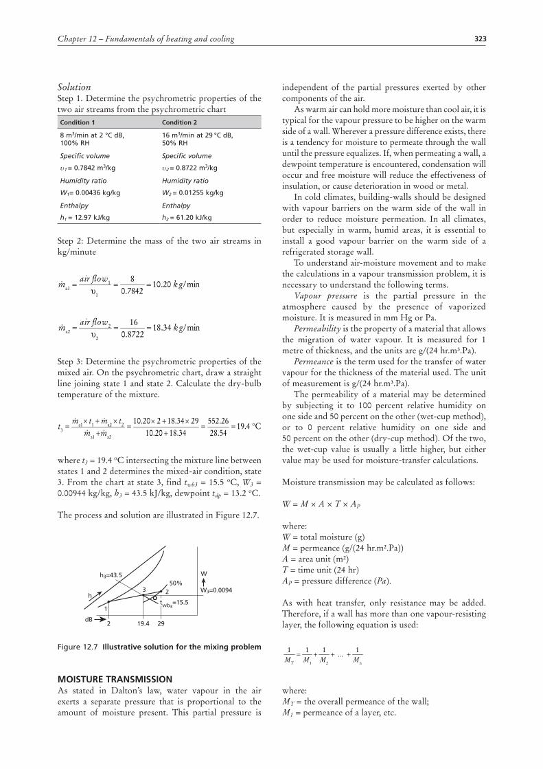
323Chapter 12 – Fundamentals of heating and cooling
SolutionStep 1. Determine the psychrometric properties of the two air streams from the psychrometric chartCondition 1 Condition 2
8 m3/min at 2 °C db,100% RH
16 m3/min at 29 °C db, 50% RH
Specific volume
υ1 = 0.7842 m3/kg
Specific volume
υ2 = 0.8722 m3/kg
Humidity ratio
W1= 0.00436 kg/kg
Humidity ratio
W2 = 0.01255 kg/kg
Enthalpy
h1 = 12.97 kJ/kg
Enthalpy
h2 = 61.20 kJ/kg
Step 2: Determine the mass of the two air streams in kg/minute
Step 3: Determine the psychrometric properties of the mixed air. On the psychrometric chart, draw a straight line joining state 1 and state 2. Calculate the dry-bulb temperature of the mixture.
where t3 = 19.4 oC intersecting the mixture line between states 1 and 2 determines the mixed-air condition, state 3. From the chart at state 3, find twb3 = 15.5 oC, W3 = 0.00944 kg/kg, h3 = 43.5 kJ/kg, dewpoint tdp = 13.2 oC.
The process and solution are illustrated in Figure 12.7.
Figure 12.7 illustrative solution for the mixing problem
moisture transmissionAs stated in Dalton’s law, water vapour in the air exerts a separate pressure that is proportional to the amount of moisture present. This partial pressure is
min/20.107842.08
kgair �ow1ma1 ===
υ1
min/34.188722.016
kgair �ow2ma2 ===
υ2
ma2ma1
t2ma2t1ma1t3 4 °C.1954.2826.552
34.1820.102934.18220.10
==+
×+×=
+×+×
=
min/20.107842.08
kgair �ow1ma1 ===
υ1
min/34.188722.016
kgair �ow2ma2 ===
υ2
ma2ma1
t2ma2t1ma1t3 4 °C.1954.2826.552
34.1820.102934.18220.10
==+
×+×=
+×+×
=
min/20.107842.08
kgair �ow1ma1 ===
υ1
min/34.188722.016
kgair �ow2ma2 ===
υ2
ma2ma1
t2ma2t1ma1t3 4 °C.1954.2826.552
34.1820.102934.18220.10
==+
×+×=
+×+×
=
W3=0.0094
Wh3=43.5
2 19.4
3 2
29
50%
twb3=15.5
1
dB
h
independent of the partial pressures exerted by other components of the air.
As warm air can hold more moisture than cool air, it is typical for the vapour pressure to be higher on the warm side of a wall. Wherever a pressure difference exists, there is a tendency for moisture to permeate through the wall until the pressure equalizes. If, when permeating a wall, a dewpoint temperature is encountered, condensation will occur and free moisture will reduce the effectiveness of insulation, or cause deterioration in wood or metal.
In cold climates, building-walls should be designed with vapour barriers on the warm side of the wall in order to reduce moisture permeation. In all climates, but especially in warm, humid areas, it is essential to install a good vapour barrier on the warm side of a refrigerated storage wall.
To understand air-moisture movement and to make the calculations in a vapour transmission problem, it is necessary to understand the following terms.
Vapour pressure is the partial pressure in the atmosphere caused by the presence of vaporized moisture. It is measured in mm Hg or Pa.
Permeability is the property of a material that allows the migration of water vapour. It is measured for 1 metre of thickness, and the units are g/(24 hr.m³.Pa).
Permeance is the term used for the transfer of water vapour for the thickness of the material used. The unit of measurement is g/(24 hr.m³.Pa).
The permeability of a material may be determined by subjecting it to 100 percent relative humidity on one side and 50 percent on the other (wet-cup method), or to 0 percent relative humidity on one side and 50 percent on the other (dry-cup method). Of the two, the wet-cup value is usually a little higher, but either value may be used for moisture-transfer calculations.
Moisture transmission may be calculated as follows:
W = M × A × T × AP
where:W = total moisture (g)M = permeance (g/(24 hr.m².Pa))A = area unit (m²)T = time unit (24 hr)AP = pressure difference (Pa).
As with heat transfer, only resistance may be added. Therefore, if a wall has more than one vapour-resisting layer, the following equation is used:
where:MT = the overall permeance of the wall; M1 = permeance of a layer, etc.
M2M1MT
111+ ...
Mn
1++=
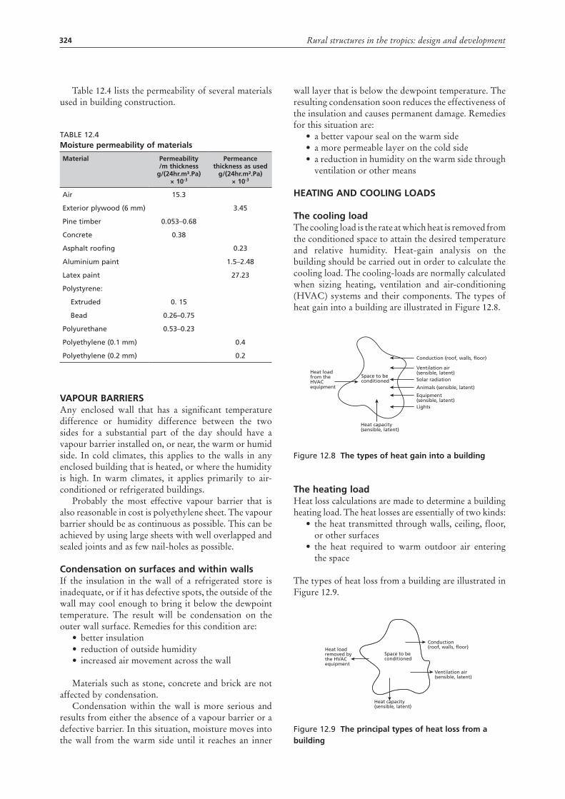
324 Rural structures in the tropics: design and development
Table 12.4 lists the permeability of several materials used in building construction.
Table 12.4moisture permeability of materials
material permeability /m thickness
g/(24hr.m³.pa) × 10-3
permeance thickness as used
g/(24hr.m².pa) × 10-3
air 15.3
exterior plywood (6 mm) 3.45
Pine timber 0.053–0.68
Concrete 0.38
asphalt roofing 0.23
aluminium paint 1.5–2.48
latex paint 27.23
Polystyrene:
extruded 0. 15
bead 0.26–0.75
Polyurethane 0.53–0.23
Polyethylene (0.1 mm) 0.4
Polyethylene (0.2 mm) 0.2
vapour barriersAny enclosed wall that has a significant temperature difference or humidity difference between the two sides for a substantial part of the day should have a vapour barrier installed on, or near, the warm or humid side. In cold climates, this applies to the walls in any enclosed building that is heated, or where the humidity is high. In warm climates, it applies primarily to air-conditioned or refrigerated buildings.
Probably the most effective vapour barrier that is also reasonable in cost is polyethylene sheet. The vapour barrier should be as continuous as possible. This can be achieved by using large sheets with well overlapped and sealed joints and as few nail-holes as possible.
Condensation on surfaces and within wallsIf the insulation in the wall of a refrigerated store is inadequate, or if it has defective spots, the outside of the wall may cool enough to bring it below the dewpoint temperature. The result will be condensation on the outer wall surface. Remedies for this condition are:
• better insulation• reduction of outside humidity• increased air movement across the wall
Materials such as stone, concrete and brick are not affected by condensation.
Condensation within the wall is more serious and results from either the absence of a vapour barrier or a defective barrier. In this situation, moisture moves into the wall from the warm side until it reaches an inner
wall layer that is below the dewpoint temperature. The resulting condensation soon reduces the effectiveness of the insulation and causes permanent damage. Remedies for this situation are:
• a better vapour seal on the warm side• a more permeable layer on the cold side• a reduction in humidity on the warm side through
ventilation or other means
Heating and Cooling loads
the cooling loadThe cooling load is the rate at which heat is removed from the conditioned space to attain the desired temperature and relative humidity. Heat-gain analysis on the building should be carried out in order to calculate the cooling load. The cooling-loads are normally calculated when sizing heating, ventilation and air-conditioning (HVAC) systems and their components. The types of heat gain into a building are illustrated in Figure 12.8.
Figure 12.8 the types of heat gain into a building
the heating loadHeat loss calculations are made to determine a building heating load. The heat losses are essentially of two kinds:
• the heat transmitted through walls, ceiling, floor, or other surfaces
• the heat required to warm outdoor air entering the space
The types of heat loss from a building are illustrated in Figure 12.9.
Figure 12.9 the principal types of heat loss from a building
Conduction (roof, walls, floor)
Heat loadfrom theHVACequipment
Heat capacity(sensible, latent)
Space to be conditioned
Ventilation air (sensible, latent)Solar radiation
Animals (sensible, latent)
Equipment (sensible, latent)Lights
Conduction (roof, walls, floor)Heat load
removed bythe HVACequipment
Space to be conditioned
Heat capacity(sensible, latent)
Ventilation air(sensible, latent)
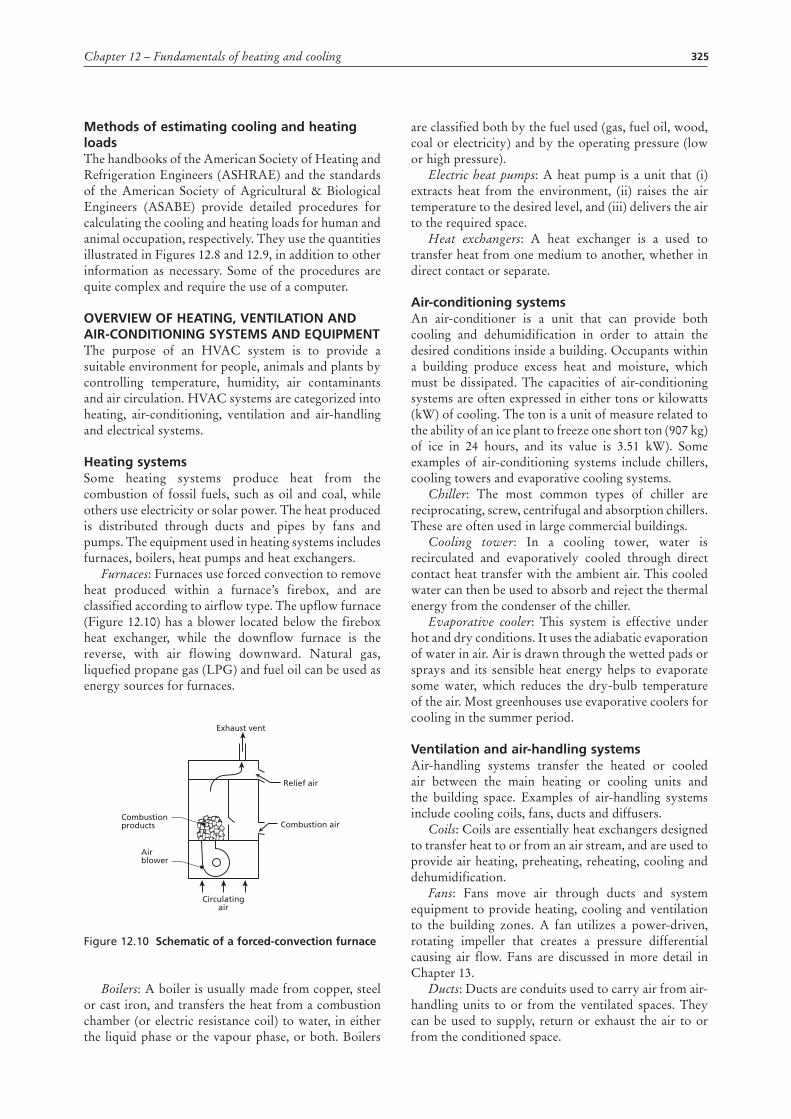
325Chapter 12 – Fundamentals of heating and cooling
methods of estimating cooling and heating loads The handbooks of the American Society of Heating and Refrigeration Engineers (ASHRAE) and the standards of the American Society of Agricultural & Biological Engineers (ASABE) provide detailed procedures for calculating the cooling and heating loads for human and animal occupation, respectively. They use the quantities illustrated in Figures 12.8 and 12.9, in addition to other information as necessary. Some of the procedures are quite complex and require the use of a computer.
overvieW oF Heating, ventilation and air-Conditioning systems and equipmentThe purpose of an HVAC system is to provide a suitable environment for people, animals and plants by controlling temperature, humidity, air contaminants and air circulation. HVAC systems are categorized into heating, air-conditioning, ventilation and air-handling and electrical systems.
Heating systemsSome heating systems produce heat from the combustion of fossil fuels, such as oil and coal, while others use electricity or solar power. The heat produced is distributed through ducts and pipes by fans and pumps. The equipment used in heating systems includes furnaces, boilers, heat pumps and heat exchangers.
Furnaces: Furnaces use forced convection to remove heat produced within a furnace’s firebox, and are classified according to airflow type. The upflow furnace (Figure 12.10) has a blower located below the firebox heat exchanger, while the downflow furnace is the reverse, with air flowing downward. Natural gas, liquefied propane gas (LPG) and fuel oil can be used as energy sources for furnaces.
Figure 12.10 schematic of a forced-convection furnace
Boilers: A boiler is usually made from copper, steel or cast iron, and transfers the heat from a combustion chamber (or electric resistance coil) to water, in either the liquid phase or the vapour phase, or both. Boilers
Exhaust vent
Relief air
Combustion airCombustion products
Circulatingair
Airblower
are classified both by the fuel used (gas, fuel oil, wood, coal or electricity) and by the operating pressure (low or high pressure).
Electric heat pumps: A heat pump is a unit that (i) extracts heat from the environment, (ii) raises the air temperature to the desired level, and (iii) delivers the air to the required space.
Heat exchangers: A heat exchanger is a used to transfer heat from one medium to another, whether in direct contact or separate.
air-conditioning systems An air-conditioner is a unit that can provide both cooling and dehumidification in order to attain the desired conditions inside a building. Occupants within a building produce excess heat and moisture, which must be dissipated. The capacities of air-conditioning systems are often expressed in either tons or kilowatts (kW) of cooling. The ton is a unit of measure related to the ability of an ice plant to freeze one short ton (907 kg) of ice in 24 hours, and its value is 3.51 kW). Some examples of air-conditioning systems include chillers, cooling towers and evaporative cooling systems.
Chiller: The most common types of chiller are reciprocating, screw, centrifugal and absorption chillers. These are often used in large commercial buildings.
Cooling tower: In a cooling tower, water is recirculated and evaporatively cooled through direct contact heat transfer with the ambient air. This cooled water can then be used to absorb and reject the thermal energy from the condenser of the chiller.
Evaporative cooler: This system is effective under hot and dry conditions. It uses the adiabatic evaporation of water in air. Air is drawn through the wetted pads or sprays and its sensible heat energy helps to evaporate some water, which reduces the dry-bulb temperature of the air. Most greenhouses use evaporative coolers for cooling in the summer period.
ventilation and air-handling systemsAir-handling systems transfer the heated or cooled air between the main heating or cooling units and the building space. Examples of air-handling systems include cooling coils, fans, ducts and diffusers.
Coils: Coils are essentially heat exchangers designed to transfer heat to or from an air stream, and are used to provide air heating, preheating, reheating, cooling and dehumidification.
Fans: Fans move air through ducts and system equipment to provide heating, cooling and ventilation to the building zones. A fan utilizes a power-driven, rotating impeller that creates a pressure differential causing air flow. Fans are discussed in more detail in Chapter 13.
Ducts: Ducts are conduits used to carry air from air-handling units to or from the ventilated spaces. They can be used to supply, return or exhaust the air to or from the conditioned space.
326 Rural structures in the tropics: design and development
Diffusers: These are usually installed at the end of the duct systems (at the point where ducts enter or exit a conditioned space) and are designed to induce air circulation, which ensures air mixing.
electrical systemsAn electrical system includes all the electrically operated equipment found inside the building or at the building site, such as lighting fixtures, appliances, motors and transformers.
Electrical motors: Motors convert electrical energy into mechanical energy and are commonly used to drive machines that, in turn, perform various functions, such as moving air (supply and exhaust fans), moving liquids (pumps), moving objects (conveyors), compressing gases (air compressors or refrigerators) and producing materials (production equipment).
Lighting systems: Lighting fixtures produce the required lighting for the occupants, as well as excess heat that must be removed by the cooling equipment.
Transformers: A transformer is a device that can change the voltage of an alternating current for different applications. A typical transformer consists of two windings: primary (connected to the power source) and secondary (connected to the load).
revieW questions1. One wall of an un-insulated house has a thickness
of 0.30 metres and a surface area of 11 m2. The wall is constructed from bricks with thermal conductivity of 0.55 W/mK. The outside temperature is -2 °C while the house temperature is kept at 25 °C. The convection heat transfer coefficient is estimated to be 21 and 7 W/m2 K for outside and inside conditions respectively. Calculate the rate of heat transfer through the wall, as well as the surface temperature on either side of the wall.
2. The air in the storage room has a dry-bulb temperature of 15 °C and 30 percent relative humidity. Determine the remaining air properties, assuming sea-level conditions.
3. A stream of 500 m3/min outdoor air at 10 °C dry-bulb temperature and 5 °C wet-bulb temperature is adiabatically mixed with 1 500 m3/min of recirculated air at 28 °C dry-bulb temperature and 50 percent relative humidity. Find the dry-bulb temperature and wet-bulb temperature of the resulting mixture. Illustrate your solution in a psychrometric chart.
4. Illustrate a heating and humidification process and derive expressions for determining (a) the rate of water evaporation and (b) the rate of heat transfer.
5. How much heat is required to heat 300 m3/min of moist air at 10 °C dry-bulb and 5 °C wet-bulb temperature to a final temperature of 30 °C dry-bulb, with no change in the humidity ratio?
FurtHer readingAmerican Society of Agricultural and Biological
Engineers (ASABE). 2009. ASABE standards. St Joseph, Michigan, United States of America.
American Society of Heating, Refrigeration and Air-conditioning Engineers (ASHRAE). 2005. ASHRAE Handbook of fundamentals. Atlanta, Georgia, United States of America.
Clifford, G. 1990. Modern heating, ventilating, and air conditioning. New Jersey, United States of America, Prentice Hall Inc.
Clifford, G.E. 1993. Modern heating and ventilating systems design. Prentice Hall, New Jersey, United States of America.
East African Meteorological Department. 1975. Climatological statistics for East Africa. Nairobi, East African Community.
Geiger, R. 1966. The climate near the ground. Cambridge, Massachusetts, Harvard University Press.
Givoni, B. 1976. Man, climate and architecture. 2nd edition. Barking, Essex, Applied Science Publishers.
Griffiths, J.F. 1976. Applied climatology: an introduction. 2nd edition. Oxford, Oxford University Press.
Haines, R.W. & Wilson, C.L. 1994. HVAC systems design handbook. New York, United States of America, McGraw Hill Inc.
Harkness, E.L. & Mehta, M.L. 1978. Solar radiation control in buildings, Barking, Essex, Applied Science Publishers.
Hellickson, M.A & Walker, J.N. 1983. Ventilation of agricultural structures. ASAE monograph No. 6. St Joseph, Michigan, United States of America.
Hooper, C. 1975. Design for climate: guidelines for the design of low-cost houses for the climates of Kenya. Nairobi, Housing Research and Development Unit, University of Nairobi.
Hydrological Survey Department. 1971. Meteorological data, Maseru, Ministry of Works and Communications.
Khashab, A.M. 1977. Heating, ventilating, and air-conditioning systems estimating manual. New York, United States of America, McGraw Hill Inc.
Koenigsberger, O.H. & Lynn, R. 1965. Roofs in the warm humid Tropics, Architectural Association Paper No. 1, London, Lund Humphries.
Koenigsberger, O.H., Ingersoll, T.G., Mayhew, A. & Szokolay, S.V. 1973. Manual of tropical housing and building, Part 1: Climatic Design. London, Longman Group Ltd.
Konya, A. 1980. Design primer for hot climates. London, Architectural Press Ltd.
Kreider, J.F. 2001. Handbook of heating, ventilation, and air conditioning. Boca Raton, Florida, United States of America, CRC Press LLC.
Lechner, N. 1991. Heating, cooling, lighting: design methods for architects. New York, United States of America, John Wiley & Sons.
327Chapter 12 – Fundamentals of heating and cooling
Mather, J.R. 1974. Climatology: fundamentals and applications. New York, McGraw-Hill.
McQuiston, F.C. & Spitler, J.D. 1992. Cooling and heating load calculation manual. 2nd edition. Atlanta, Georgia, United States of America, ASHRAE, Inc.
Meteorological Department. 1971. Climatological summaries for Zambia. Lusaka.
Oakley, D. 1961. Tropical houses: a guide to their design. London, B.T. Batsford Ltd.
Olgyay, V. & Olgyay, A. 1976. Solar control and shading devices. Princeton, New Jersey, Princeton University Press.
Olgyay, V. 1963. Design with climate: bioclimatic approach to architectural regionalism. Princeton, New Jersey, Princeton University Press.
Pederson, C.O., Fisher, D.E, Spitler, J.D. & Liesen, R.J. 1998. Cooling and heating load calculation principles. Atlanta, Georgia, United States of America, ASHRAE Inc.
Van Straaten, J.F. 1967. Thermal performance of buildings. Amsterdam, Elsevier.
Wang, S.K. 2000. Handbook of air conditioning and refrigeration. New York, McGraw Hill Inc.
Whitaker, J.H. 1979. Agricultural buildings and structures, Reston, Virginia, Reston Publishing Co.