Embed Size (px)
Citation preview

1
Index
Soldering point.
Male connector.
Female connector.
M/F faston connector.
Test point.Supply voltage. Logic supply ground.
Analog supply ground.
Chassis ground.
Earth ground.
Flag joined with one or more flags
GENERALMUSIC S.p.A. Sales Division: 47842 S.Giovanni in Marignano (RN) ITALY - Via delle Rose, 12
Phone +39(0)541/959511 - Fax +39(0)541/957404 - GENERALMUSIC on the NET: http://www.generalmusic.com
Opening & Keyboard Disassembling Instructions2
Autotest Procedure
Autotest Procedure, Frequently Asked Questions
3
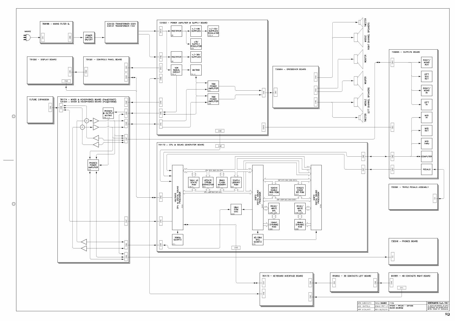
Block Diagram5
6
Keyboard Interface and L/R Contact Boards7
Power Amplifier & Supply, Outputs and Phones Boards
8
Cpu & Sound Generator Board Layout & Timing Table9
Spare Part List
10
12
Controls Panel and Display Boards
Cpu & Sound Generator Board
4
SERVICE MANUAL
CODE: 270247
Warnings
with the same signal name inscribed.
AddressATTENTION Observe
precautions when handling electrostatic sensitive devices.
NoticeService must be carried out by qualified personnel only. Any tampering carried out by unqualified personnel during the guarantee period
will forfeit the right to guarantee.
For a correct operation of the instrument, after having switched off, be careful to wait at least 3 seconds before switching on again.
To improve the device's specifications, the schematic diagrams may be subject to change without prior notice.
All components marked by this symbol have special safety characteristics, when replacing any of these components use only
manufacturer's specified parts.
The (µ) micro symbol of capacitance value is substituted by U.
The (Ω) omega symbol of resistance value is substituted by E.
The electrolytic capacitors are 25Vdc rated voltage unless otherwise specified.
All resistors are 1/8W unless otherwise specified.
All switches shown in the "OFF" position. All DC voltages measured to ground with a voltmeter 20KOhm/V.

2
1) TO REMOVE THE COVER UNSCREW THE 4 SCREWS ON THE REAR, PULL THE COVER TOWARDS YOU AND LIFT IT UP. 3) TO REMOVE THE CONTROL PANEL UNSCREW THE SCREWS AT EACH END AND THE SCREWS THAT ANCHOR
4) TO REMOVE THE KEYBOARD UNSCREW THE 8 SCREWS UNDER THE KEYBOARD.
THE CONTROL PANEL SUPPORTS TO THE CHASSIS.
APP.
CKD
DRW
REV:
DISK:
DWG#
PRT:
PCB# GENERALMUSIC S.p.A. ITALY
ALL RIGHTS ARE RESERVED, NO COPIES
WRITTEN CONSENT BY GENERALMUSIC.OR REPRODUCE THIS DOCUMENT WITHOUT
G.Boccato
I.Battelli
M.Galanti
500935
1/1
01/02/01
RP220Opening Instructions& Keyboard disassembling
2) TO REMOVE THE KEYBOARD COVER UNSCREW THE FOUR SCREWS ON THE BARS (TWO FOR EACH SIDE),
AND PULL OUT THE KEYBOARD COVER.
NOTE: TO REMOVE A SHARP KEY BEFORE YOU MUST REMOVE THE NEAR NATURAL KEYS.
REMOVE THE KEY RETURN SPRING.
UNLOCK THE KEY APPLING NOT MUCH STRENGTH.
TP10

3
rev. 02-02-01
Operations Description DisplayThe following procedures must be executed subsequently in the specified order.Before turn on the instrument check the jumpers setting on CPU & SOUND GENERATOR BOARD corresponds at the model accordingly to the following table:
MODEL J4 J5 J3 J6 J2RP200 GEM 1-2 1-2 1-2 1-2 1-2RP200 BALDWIN 1-2 1-2 1-2 1-2 2-3GRP300 GEM 1-2 1-2 1-2 2-3 1-2 v.2.00 or greaterGRP300 BALDWIN 1-2 1-2 1-2 2-3 2-3 v.2.00 or greaterRP220 GEM 1-2 1-2 2-3 1-2 1-2 v.2.02 or greaterRP220 BALDWIN 1-2 1-2 2-3 1-2 2-3 v.2.02 or greater
Remove the secondary fuses F1, F2, F3, located on POWER AMPLIFIER & SUPPLY BOARD; turn on the instrument and verify the supply AC voltages: (CN6) between pin1 and pin2 = 27,5 ± 1,5Vac (CN6) between pin1 and pin3 = 27,5 ± 1,5Vac (CN6) between pin2 and pin3 = 55 ± 3Vac (CN12) between pin1 and pin2 = 16 ± 0,8Vac (CN12) between pin1 and pin3 = 16 ± 0,8Vac (CN12) between pin2 and pin3 = 32 ± 1,6Vac
Turn off the instrument, and put the fuses back on its holders.
Turn on the instrument and the appropriate welcome message appears on the display.
A few seconds later the led GRAND PIANO light.Check the supply DC voltages on CPU & SOUND GENERATOR BOARD: (CN8) between pin9 and pin7 = +5 ± 0,25Vdc (CN8) between pin1 and pin4 = +12 ± 0,6Vdc (CN8) between pin1 and pin5 = -12 ± 0,6Vdc
|INTERNAL PRESET|| GRAND PIANO ||GR.PIANO sel.:1|
RP200-220 GRP300 AUTOTEST PROCEDURE
Operations Description Display
The instrument starts in AUTOTEST mode turning on the instrument while pressing down the "GRAND PIANO" button (pressing PRESET instead GRAND PIANO the procedure starts from LCD display test).NOTE: Each time you press the "GRAND PIANO" button the autotest procedure proceeds to the next step.
| RP98 || AUTOTEST || |
Set the default display contrast in the ± 6 range by pressing the DATA + or - buttons.|CONTRAST = # || || |
The instrument shows the date, time and release version of the software loaded in flash memory.| mmm dd yyyy ||hh:mm:ss V #.##|| |
The instrument asks if you want to update it, press GRAND PIANO to skip, the appropriate procedure to update the software is explained further.
|EPROM to FLASH ||push REC to prog|| |
The instrument performs the flash memory data checksum and display it in hexadecimal value.NOTE: the BT (boot) value must be EAAB for ver.2.00, if it does not correspond you can not update software thru serial port but only with Update Software Board see more further.For example version 2.02 has BT=EAAB PR=A5F4 and ALL=909F.
|Wait * ||Eprom Checksum || |
|cks BT PR ALL|| #### #### ####|| |
The instrument performs the "LIBRARY" Rom memory data checksum and display it in hexadecimal value.
|Wait * ||Library Checksum|| |
|Wait ok! ||Checksum: A021|| |
The instrument performs the RAM memory test showing the address checked.|RAM MEMORY CHECK||addr 23BFFF OK|| |
The LCD display test fades from light to dark and viceversa.| |
| |
| |
Check that all leds are lighting.|--- LED TEST ---||Are all leds on?|| |
RP200-220 GRP300 INITIAL CHECK
| RP200 || REALPIANO || GEM |
| PIANOVELLE || RP200 || BALDWIN |
| GRP300 || REALPIANO || GEM |
| PIANOVELLE || GRP300 || BALDWIN |
| RP220 || REALPIANO || GEM |
| PIANOVELLE || RP220 || BALDWIN |
Check the VOLUMES ranges from 0 to 127.Check all buttons (except GRAND PIANO) pressing their one at a time and checking that corresponding led lights, pressing PAGE UP and DOWN buttons the display shows "U" and "D", pressing DATA + and - buttons the display shows "+" and "-", pressing MASTER EQ and DSP buttons the display shows an "X" in 1 and 2 digits, pressing UP, LEFT, DOWN and RIGHT buttons the display shows an "X" in 3, 4, 5 and 6 digits respectively.
| |Button test || |Vol:0 || 123456|
|U|Button test +||D|Vol:127 -|| XXXXXX|
Check the SOFT and SUSTAIN pedals, pressing each one the value change from 0 (released) to 127 (pressed), the DAMPER pedal varying its value continuosly from 0 (released) to nearly 127 (pressed).
|Soft Sust Damp|| 0 0 0|| |
Check the MIDI I/O connecting the MIDI OUT and MIDI IN sockets by a MIDI cable.|TEST MIDI IN/OUT||LOOP DETECTED OK|| |
Check COMPUTER I/O shorting pin 3 and pin 5 on the COMPUTER socket, check with the oscilloscope a 4Vpp (1Mhz) signal on pin 1, set volume to half stroke.
|TST COMPUTER I/O||LOOP DETECTED OK|| |
The instrument generates a 1KHz sinusoidal signal in both audio channels reading data from 104043 ROM. VOLUME controls the amplitude of signal and TRANSPOSE b and # buttons controls the frequency from 10Hz to 2756Hz.
| SINUS. SWEEP ||Freq. 1000 Hz|| |
Re-set the frequency at 1KHz and check HEADPHONES and AUX outputs with the oscilloscope inserting a stereo jack in the left phones socket (speakers will go be silent) and two mono jack in the AUX OUT sockets and set volume to its maximum.
Now verify the following level of signals:Phones output without load = 5,7 ± 1.1Vpp and AUX output = 0,8 ± 0,16Vpp
Set the VOLUME to minimum.
Apply a sinusoidal signal of 0.730Vpp at 1KHz with a generator to the AUX IN left and right sockets and verify the signal output:AUX output = 1,35 ± 0.07Vpp
The instrument generates a tone signal in both audio channels reading data from 104023 ROM.|TONE ON 104023 || || |
Autotest is over, turn off the instrument.|TEST END: SWITCH||POWER TO RESTART|| |
RP200-220 GRP300 O.S. UPDATING PROCEDURE up to ver. 2.00 with Updating Software Board (751180)
Operations Description Display
Start with the instrument in AUTOTEST mode as described above and press GRAND PIANO 2 times until the display show the software version loaded in flash memory.
| mmm dd yyyy ||hh:mm:ss V #.##|| |
Press GRAND PIANO to skip this procedure.|EPROM to FLASH ||push REC to prog|| |
The instrument performs the flash memory data checksum and displays it in hexadecimal value.
|Wait * ||Eprom Checksum || |
|cks BT PR ALL|| #### #### ####|| |
Compare the software version and checksum with the value imprinted onto the EPROM, if one of these does not match, the system must be upgraded, proceed to the next step.Turn off the instrument.
Insert the EPROM BOARD (where the operating system is stored) in the CN3 connector located on CPU & SOUND GENERATOR BOARD.
Start with the instrument in AUTOTEST mode as described above and press GRAND PIANO 3 times.
When the display shows this message press REC.|EPROM to FLASH ||push REC to prog|| |
The instrument erases the previous data in flash memory. After which the instrument displays the amount of memory programming and finally the operation successful. If the programming fails check the EPROM BOARD connection and repeat this procedure from start.
|EPROM to FLASH ||erasing || |
|EPROM to FLASH ||prog: 1024/1024K|| |
The instrument performs the eprom memory data checksum and display it in hexadecimal value, compare this value with the value imprinted onto the EPROM: if it matches the EPROM is good.
|Wait * ||Eprom Checksum || |
|cks BT PR ALL|| #### #### ####|| |

4
Turn off the instrument and disconnect the EPROM BOARD.
Start with the instrument in AUTOTEST mode as described above and press GRAND PIANO 2 times until the display show the new software version loaded in flash memory.
| mmm dd yyyy ||hh:mm:ss V #.##|| |
Press GRAND PIANO to skip this procedure.|EPROM to FLASH ||push REC to prog|| |
The instrument performs the flash memory data checksum and display it in hexadecimal value, compare this value with the value imprinted onto the EPROM: if it matches the procedure has been executed succesfully.
|Wait * ||Eprom Checksum || |
|cks BT PR ALL|| #### #### ####|| |
The procedure proceed as described in AUTOTEST section, if you do not want to check the rest of the instrument simply turn off it.
RP200-220 GRP300 O.S. UPDATING PROCEDURE from Serial Port (COMPUTER) ver. 2.xx or greater
Operations Description Display
NOTE: This procedure is valid only if the software version installed on the piano is the 2.00 or greater.Some additional tips and advices are included in the Flashblaster Firmware Update Disk. The disk containing the Fblaster program can also be downloaded by internet at generalmusic web site (www.generalmusic.com) or required at [email protected]
Connect the serial cable between the COMPUTER of the piano and the RS232 COM port of the computer (PC-Ibm or compatible).
Insert the disk in the drive A (or whatever your 3.5" drive is assigned to), open the contents of drive A and double click on the fblaster.exe file.
From the OPTIONS/SETTINGS menu, make sure that the TEST AND PROGRAM choice is selected. This is very important.
Turn on the piano, while holding down the REC button until the display shows:|READY TO UPDATE || || |
Click with the mouse on the GO! button or, from the ACTION menu, select EXECUTE (ALT+A, E). The piano display appears as follows:
|TESTING... ||n1/n2 PACKETS || |
At the end of the test the following display appears:| TEST OK || || |
After a short time, the following display appears:|ERASING... || || |
You are now erasing the old operating system from FLASH memory. When the system is erased, the following display appears as your new operating system is installed into Flash Memory:
|UPDATING... ||n1/n2 PACKETS || |
When the entire update procedure is completed, the following display appears:|UPDATE_OK:SWITCH||POWER TO RESTART|| |
The update has now been successfully completed. Turn off the power switch on the piano, and turn it back on again to use your updated instrument.
RP200-220 GRP300 Some Repairing Tips
Operations Description DisplayThis message could be appear if an error occur on the communication channel.Possible solutions:1) inconsistent data received on MIDI or COMPUTER input socket, check the ratings of the device connected to the piano.2) if the error persist, try to replace Outputs Board first and CPU board second.
|MIDI SCI error || || |
This message could be appear if an error occur on the communication channel.Possible solutions:1) verify all the connections between Keyboard Interface Board and the CPU board.2) if the error persist, try to replace Keyboard Interface Board first and CPU board second.
|VALIS SCI error || || |
This message could be appear if an error occur on the communication between CPU and DISP3 chips.Possible solutions:1) verify all the tracks, solders and components between CPU and DISP3 chips as shown in schematics.2) if the error persist, replace the CPU board and send back to generalmusic the failed CPU board.
|Disp Failure || || |
rev. 19-07-00
Questions Answers
1 What do the pedals make?
Soft (left pedal):This pedal is a switch control pedal (on/off) and affects the timbre of the instrument such that it plays softer, allowing you to continue using the same playing style at a lower volume.Sostenuto only for some models (centre pedal):This pedal is a switch control pedal (on/off) which sustains the notes of the key currently depressed, all new notes played after having depressed the pedal are not affected, this pedal operates like a grand piano centre pedal.Damper (right pedal):This pedal applies the sustain effect to all notes released. If you release a note after depressing the damper, the note will proceed towards its natural decay according to the type of sound played.The Damper pedal is particularly effective with Piano type sounds, it is controlled by a "Damper Physical Model" patented by Generalmusic.
2Why do the uppermost keys play always sustained?
For all piano sounds the notes from E6 to C8 are automatically sustained such as in an acoustic piano.
3 Why do all pedals work in reverse mode?
The instrument reads the status of the pedals at the power on and assume this status (normally open or normally closed depends by the type of pedal) as the default status in the rest position.The pedals must be inserted before you switch on the instrument.
4 Why do some pedal work in reverse mode?For the same reason explained first you have not to press a pedal while the instrument is switched on and until it is ready to use.
5I have replaced the DAMPER pedal potentiometer, how do I let position it correctly?
Set the potentiometer to have about 700 ohm between pin 5 and 1 of DIN plug with the pedal at the rest position.Note: the Damper potentiometer have a special resistive stroke, when you replace it use the manufacturer's part only (code 070556).
6 How can I do a complete SYSTEM RESET?Turn on the instrument while pressing down the "General" button.Each time you do an autotest procedure a system reset is performed.
7Why does not the instrument respond correctly to the key pressed on keyboard after I have replaced the CPU Board?
If the CPU Board replaced is the right type check the jumper setting on it as described on this service manual and execute a complete Autotest.
8Why does not the instrument respond correctly to the button pressed on controls panel after I have replaced the CPU Board?
If the CPU Board replaced is the right type check the jumper setting on it as described on this service manual and execute a complete Autotest.
9Why does not the instrument respond correctly to the pedal pressed after I have replaced the CPU Board?
If the CPU Board replaced is the right type check the jumper setting on it as described on this service manual and execute a complete Autotest.
10Why does not the Instrument retain the user presets and data?
After a long period of inactivity may be occur that the internal battery backup have not a sufficient time for re-charging during the normal activity, try to leave the instrument switched on for about 12-14 hours. Afterwards if the instrument will lost the data again, replace the battery.
RP series FAQ
5

6

7

8

9
CPU & SOUND GENERATOR BOARD (PCB#310603)

10

11

12
Spare Part List
LegendEU = Specify European Version (230Vac)US = Specify United States Version (115Vac)R = Rosewood FinishB = Gloss Black FinishM = Mahogany FinishW = Gloss White FinishGem = Gem VersionBaldwin = Baldwin VersionCode Description
Optional Accessories
130301 2mt Midi Cable970296 Pianist’s Bench (R)970297 Pianist’s Bench (B)970319 Pianist’s Bench (M)970298 Pianist’s Bench (W)
Accessories
271310 Owner’s Manual (Italian-English-French-German) (Gem)271311 Owner’s Manual (English-French-Spanish) (Baldwin)130274 Mains Cable (EU)130276 Mains Cable (US)
Consolette
830756 Stand & Pedals Assembly (R)830763 Stand & Pedals Assembly (B)830765 Stand & Pedals Assembly (M)830764 Stand & Pedals Assembly (W)720616 * Crossbar with Pedals (B) (M) (R)720626 * Crossbar with Pedals (W)720613 ** Triple Pedal Assembly (replace entirely)660655 ** Crossbar (B) (M) (R)660667 ** Crossbar (W)210018 ** 1x5mm Adhesive Red Felt (specify mt)710573 * Speakers Box770883 ** Speakers Box Cables Assembly130270 *** Speakers Cable with Jack Plug340928 ** Plastic Speaker Box262083 ** 150x391mm Wood Panel262082 ** 150x800mm Wood Panel262036 ** Rear Panel262035 ** Front Panel261866 ** 20x20x200mm Deal Fillet220120 ** 6" 8ohm Full-range Speaker220118 ** 8" 8ohm Woofer Speaker210242 ** Filler for Speaker Box (Specify m²)210217 ** Black Sealer (specify mt)210215 ** Adhesive Rubber Foam 10x1.9mm (Specify mt)210054 ** 1x5mm Adhesive Spik (specify mt)120684 ** M4x10 Sleeve120413 ** WL3.5x30tt Black Screw120374 ** WL4x15tt Black Screw120063 ** M4x20tc Black Screw660407 * Support for Rear Panel262031 * Foot (R)262178 * Foot (B)262180 * Foot (M)262179 * Foot (W)262030 * Left Leg (R)262175 * Left Leg (B)262177 * Left Leg (M)262176 * Left Leg (W)262029 * Right Leg (R)262172 * Right Leg (B)262174 * Right Leg (M)262173 * Right Leg (W)171702 * Right Cabinet Support171701 * Left Cabinet Support171505 * Angular Fixing170585 * Metal Foot129073 * WL4.5x50ts Screw120681 * MA6x13 Sleeve120523 * 6mm Black Spring Washer120489 * 14x6.4x2 Black Nylon Washer120341 * WL4x20tt Black Screw120128 * M6x35tc Black Screw120119 * M4x16tc Black Screw120070 * M6x20tc Black Screw
Cabinet
710638 Cover Assembly (R)710639 Cover Assembly (B)
710640 Cover Assembly (M)710641 Cover Assembly (W)340960 * Music Stop (R)(M)653503 * Music Stop (B)653504 * Music Stop (W)262299 * Cover (R)262300 * Cover (B)262301 * Cover (M)262302 * Cover (W)262271 * Fillet262037 * Front Cover Bar (R)262181 * Front Cover Bar (B)262183 * Front Cover Bar (M)262182 * Front Cover Bar (W)120463 * 4.3x12.5x1 Black Washer120322 * WL4x15tc Black Screw120288 * WL3x20tc Black Screw710634 Cabinet Assembly (R)710635 Cabinet Assembly (B)710636 Cabinet Assembly (M)710637 Cabinet Assembly (W)770903 * Speakers Cables Assembly660609 * Speaker Jack Socket Support660405 * 50x240mm Heatsink Grid510302 * Wooden Parts (R)510303 * Wooden Parts (B)510304 * Wooden Parts (M)510305 * Wooden Parts (W)262294 ** Rear Panel (R)262295 ** Rear Panel (B)262296 ** Rear Panel (M)262297 ** Rear Panel (W)262042 ** Keyboard Cover Guide262024 ** Left Side (R)262163 ** Left Side (B)262165 ** Left Side (M)262164 ** Left Side (W)262023 ** Right Side (R)262160 ** Right Side (B)262162 ** Right Side (M)262161 ** Right Side (W)261799 ** Keyboard Cross-Bar (R)261836 ** Keyboard Cross-Bar (B)261957 ** Keyboard Cross-Bar (M)261852 ** Keyboard Cross-Bar (W)210054 * 1x5mm Adhesive Spik (specify mt)171756 * Angular Fixing171606 * Angular Reinforcement171605 * Keyboard Crossbar Support171331 * Left Cover Clamp171330 * Right Cover Clamp120684 * M4x10 Sleeve120681 * MA6x13 Sleeve120374 * WL4x15tt Black Screw120341 * WL4x20tt Black Screw120340 * WL4x12tt Black Screw120312 * WL4x10tt Black Screw710643 Music Stand Assembly (R)(Gem)710645 Music Stand Assembly (B)(Gem)710647 Music Stand Assembly (M)(Gem)710642 Music Stand Assembly (R)(Baldwin)710644 Music Stand Assembly (B)(Baldwin)710646 Music Stand Assembly (M)(Baldwin)710648 Music Stand Assembly (W)(Baldwin)660406 * Stop Pinch Bar for Music Stand323062 * Adhesive Bumpon Rubber262051 * Music Stand (R)262220 * Music Stand (B)262222 * Music Stand (M)262221 * Music Stand (W)171361 * Music Stand Hinge120289 * WL3x10ts Black Screw120272 * WL3x10tc Black Screw710575 Keyboard Cover (R)710595 Keyboard Cover (B)710597 Keyboard Cover (M)710596 Keyboard Cover (W)324405 * Hinge between Front and Top Keyb. Covers323069 * 11.1X5mm Bumpon Rubber320400 * WL2.6x9.5tsp Brass Screw262041 * Revolving Cross Bar (R)262193 * Revolving Cross Bar (B)262195 * Revolving Cross Bar (M)262194 * Revolving Cross Bar (W)262040 * Cover Finishing (R)
262190 * Cover Finishing (B)262192 * Cover Finishing (M)262191 * Cover Finishing (W)262039 * Rear Cover (R)262187 * Rear Cover (B)262189 * Rear Cover (M)262188 * Rear Cover (W)262038 * Front Cover (R)262184 * Front Cover (B)262186 * Front Cover (M)262185 * Front Cover (W)210017 * 2x10mm Adhesive Black Felt (specify mt)171774 * Hinge between Covers171628 * Angular Guide120684 * M4x10 Sleeve120336 * WL4x25tt Black Screw120034 * M4x12tc Black Screw262033 Rear Stand Panel120523 6mm Black Spring Washer120489 14x6.4x2 Black Nylon Washer120456 6.5x12.5x1.5 Black Washer120412 WL4x35tt Burnished Screw120080 M6x30tc Black Screw120073 M6x50te Black Screw120070 M6x20tc Black Screw653491 Left Cheek Block for Keyboard (R)(M)653456 Left Cheek Block for Keyboard (B)653493 Left Cheek Block for Keyboard (W)653490 Right Cheek Block for Keyboard (R)(M)653455 Right Cheek Block for Keyboard (B)653462 Right Cheek Block for Keyboard (W)340933 5x5.9x12 Insulated Bush340916 Button for Power Switch340329 Rubber Bush for Cable340075 PC-Board Spacer210016 1x10mm Adhesive Black Felt (specify mt)180779 210x62mm “Gem” Adhesive180675 40.5x12 “Gem” Adhesive Plate180674 20x24mm “GM” Logo Adhesive Plate180785 13X71MM “Pianovelle” Adhesive180781 75x17mm “Pianovelle” Adhesive180780 210x62mm “Baldwin Pianovelle” Adhesive180676 82x13.3mm “Baldwin” Logo Adhesive Plate171758 Left Arm for Keyboard Cover171757 Right Arm for Keyboard Cover171738 Mains Switch Support120968 Bush for Keyboard Cover120581 M3 Black Self-Locking Nut120522 4mm Black Spring Washer120489 14x6.4x2 Black Nylon Washer120463 4.3x12.5x1 Black Washer120412 WL4x35tt Burnished Screw120405 B3.5x9.5tc Black Screw120341 WL4x20tt Black Screw120340 WL4x12tt Black Screw120293 WL3x25ts Brassed Screw120289 WL3x10ts Black Screw120117 M4x8tc Black Screw120094 M3x30tsp Black Screw120063 M4x20tc Black Screw120059 M4x25tc Black Screw120028 M3x6tc Black Screw120025 M3x10tsp Black Screw
Mains & Transformer Assembly
110614 Mains Socket770904 Mains Cables Assembly110320 * Power Switch768198 Mains Filter Board (Pcb#310643)230565 * 2.5mH 250V 3A AC Line Filter140010 * 3 Contacts P=10 Vert Terminal Block020493 * 100n 250Vac MKP EMI Capacitor “Siemens”010545 * 4n7 250V Ceramic Capacitor (Iec-Ul-Csa)230130 Transformer 230Vac 220W (EU)230131 Transformer 115Vac 220W (US)
Power Amplifier & Supply Board
110020 T5A Fuse 5x20mm (EU)110010 T2A Fuse 5x20mm (EU)110083 T2A Fuse 6.3x32mm (US)110021 T5A Fuse 6.3x32mm (US)731004 Power Amplifier & Supply Board (Pcb#310604)340154 * TO3/TO218 Mica Washer340079 * TO220 Mica Washer340078 * TO220 Insulated Bush
230527 * BL02RN2-R62 EMI Coil For Signal230524 * 100uH Switching Coil171660 * Right Support Board171659 * Left Support Board171658 * Heatsink170716 * TO220 38mm height Heatsink141101 * 4 Contacts Vert Male Connector141010 * 4 Contacts Vert Female Connector140929 * 9 Contacts Vert Male Connector140917 * 2 Contacts Vert Male Connector140908 * 6 Contacts Vert Male Small Connector140010 * 3 Contacts P=10 Vert Terminal Block120857 * Vertical Male Faston 6.3mm120581 * M3 Black Self-Locking Nut120521 * 3mm Black Spring Washer120255 * B2.9x6.5tc Screw120003 * M3x8tc Black Screw110119 * Fuse Clip 10A max (EU) (US)100965 * TDA7294 70W Audio Amplifier with Mute100900 * L4960 5-40V 2.5A Switching Regulator100045 * 7812 +12V 1A Voltage Regulator100043 * 7912 -12V 1A Voltage Regulator090183 * BC550C TO92 LN Npn Transistor080605 * KBL02 4A 200V Rectifier Diode Bridge080171 * FE6B 6A 100V Fast Recovery Diode080156 * 1N4002 1A 100V Rectifier Diode080103 * 1N4148 100mA 75V Signal Diode052060 * 100K 1/8w 5% Resistor052054 * 33K 1/8w 5% Resistor052052 * 22K 1/8w 5% Resistor052050 * 15K 1/8w 5% Resistor052048 * 10K 1/8w 5% Resistor052040 * 2K2 1/8w 5% Resistor052036 * 1K 1/8w 5% Resistor052024 * 100E 1/8w 5% Resistor050131 * 10E 1/4W 5% Resistor030950 * 470u 16V 20% Low Esr Vert Electrolytic Capacitor030929 * 4u7 35V 20% Electrolytic Tantalium Capacitor030880 * 10000uF 25V Snap-In Electrolytic Capacitor030856 * 4700uF 25V Snap-In Electrolytic Capacitor030555 * 4700u 50V 20% Snap-In Electrolytic Capacitor030486 * 100u 50V 20% Vert Electrolytic Capacitor030485 * 100u 25V 20% Vert Electrolytic Capacitor030403 * 47u 25V 20% Vert Electrolytic Capacitor030324 * 22u 50V 20% Vert Electrolytic Capacitor030245 * 10u 50V 20% Vert Electrolytic Capacitor030082 * 2u2 50V 20% Vert Electrolytic Capacitor030005 * 1u 50V 20% Vert Electrolytic Capacitor021028 * 220n 63V 10% MKT Polyester Capacitor021024 * 100n 63V 10% MKT Polyester Capacitor021018 * 33n 63V 10% MKT Polyester Capacitor021004 * 2n2 63V 10% MKT Polyester Capacitor010595 * 100n 50V -20+80% Ceramic Cap. Multilayer010462 * 1n 50V 10% CL2 Ceramic Capacitor010402 * 330p 50V 10% CL2 Ceramic Capacitor
Crossover & Tweeter Assembly
731029 Crossover Board (Pcb#310651)230587 * 3.5mH 0.56mm Crossover Core Coil230533 * 0.45mH 1mm Crossover Coil141101 * 4 Contacts Vert Male Connector120581 * M3 Black Self-Locking Nut120013 * M3x25tc Black Screw030348 * 47u 100V 20% Axial Electrolytic Bipolar Capacitor030171 * 4u7 63V 20% Axial Electrolytic Bipolar Capacitor229015 1" 8ohm Dome Tweeter Speaker171780 Tweeter Support
Keyboard Assembly
720568 Keyboard Assembly (TP10MDS)840762 * 20 Wires 25cm Length Flat Cable840761 * 20 Wires 12.5cm Length Flat Cable761173 * Keyboard Interface Board (Pcb#315024)141018 ** 20 Contacts Vert Female Connector141011 ** 6 Contacts Vert Female Connector140918 ** 2 Contacts Hor Male Connector100740 ** HD6433278 Cpu F=20MHz100605 ** 74HC125 Quad 3-State Buffer050493 ** 10Kx4 1/8w 5% Resistor Array050492 ** 10Kx8 1/8w 5% Resistor Array050414 ** 2K2x4 1/8w 5% Resistor Array010725 ** 20MHz Ceramic Resonator With Capacitors010662 ** 220p 10% 50V X8 Cap Array010661 ** 47p 10% 50V X8 Cap Array720559 * Keyboard Assembly (TP10MDS)

13
840738 ** 4 Wires 5cm Length Flat Cable810552 ** 39N Left Contacts Board (Pcb#310531)340764 *** 3 Dual Contacts Rubber Strip340211 *** 12 Dual Contact Rubber Strip141018 *** 20 Contacts Vert Female Connector141010 *** 4 Contacts Vert Female Connector080103 *** 1N4148 100mA 75V Signal Diode810551 ** 49N Right Contacts Board (Pcb#310530)340212 *** 13 Dual Contact Rubber Strip340211 *** 12 Dual Contact Rubber Strip141018 *** 20 Contacts Vert Female Connector141010 *** 4 Contacts Vert Female Connector080103 *** 1N4148 100mA 75V Signal Diode500074 ** Mechanicals Parts (TP10MDS)160214 *** Sharp Key Return Spring (TP10MDF/s)160213 *** Natural Key Return Spring (TP10MDF/s)151226 *** Last C Key (TP10MDS)151225 *** First A Key (TP10MDS)151224 *** Sharp Key (TP10MDS)151223 *** B Key (TP10MDS)151222 *** A Key (TP10MDS)151221 *** G Key (TP10MDS)151220 *** F Key (TP10MDS)151219 *** E Key (TP10MDS)151218 *** D Key (TP10MDS)151217 *** C Key (TP10MDS)120272 ** WL3x10tc Black Screw340092 * 5mm Board Spacer210017 * 2x10mm Adhesive Black Felt (specify mt)120288 * WL3x20tc Black Screw
Controls Panel Assembly
820618 Controls Panel Assembly (R)(M)820619 Controls Panel Assembly (B)820620 Controls Panel Assembly (W)841247 * 20 Wires 32cm Flat Cable with Ferrite and 3 blocks840844 * 2 Wires 7.5cm Length Crimp Terminal Cable810678 * Controls Panel & Display Board Assembly731001 ** Controls Panel Board (Pcb#310622)141018 *** 20 Contacts Vert Female Connector140918 *** 2 Contacts Hor Male Connector140529 *** Microswitch 12V 50mA 0.25mm100606 *** 74HC138 1 Of 8 Decoder090194 *** BC560C TO92 LN Pnp Transistor080752 *** Led 3mm Wide Diffused Red080724 *** Led 3mm 40deg High Eff Green080103 *** 1N4148 100mA 75V Signal Diode070551 *** 10K Linear 30mm Slider Potentiometer052060 *** 100K 1/8w 5% Resistor052052 *** 22K 1/8w 5% Resistor052036 *** 1K 1/8w 5% Resistor052028 *** 220E 1/8w 5% Resistor030403 *** 47u 25V 20% Vert Electrolytic Capacitor030245 *** 10u 50V 20% Vert Electrolytic Capacitor010595 *** 100n 50V -20+80% Ceramic Cap. Multilayer731000 ** Display Board (Pcb#310637)141018 *** 20 Contacts Vert Female Connector140918 *** 2 Contacts Hor Male Connector140874 *** Single In Line Vert Male Strip (specify contacts)090194 *** BC560C TO92 LN Pnp Transistor080754 *** LMC97S005A Lcd Display 128X64 dots080103 *** 1N4148 100mA 75V Signal Diode052051 *** 18K 1/8w 5% Resistor052039 *** 1K8 1/8w 5% Resistor040095 *** 6E8 1/2W 5% Resistor030246 *** 10u 25V 20% Low Prof Vert Electrolytic Capacitor030006 *** 1u 50V 20% Low Prof Vert Electrolytic Capacitor010595 *** 100n 50V -20+80% Ceramic Cap. Multilayer010387 *** 220p 50V 10% CL2 Ceramic Capacitor120579 ** M2 Nut120145 ** M2x10tc Black Screw660700 * Controls Panel (R)(M)660701 * Controls Panel (B)660702 * Controls Panel (W)653488 * <+/-> Rubber Pad653487 * <<>> Rubber Pad653485 * <DEMO-VIBES> Rubber Pad653484 * <PLAY-REC> Rubber Pad653482 * <SPLIT-EQUAL.> Rubber Pad653481 * <GRAND-PIANO> Rubber Pad652735 * Display Screen651563 * Cloth For Panel Slits340915 * LED Lens340820 * Slider Knob340523 * 6.5mm Spacer
340512 * Slider Potentiometer Guide210258 * Slider Potentiometer Felt210020 * 1.5x12mm Adhesive Red Felt (specify mt)210017 * 2x10mm Adhesive Black Felt (specify mt)171819 * Controls Panel Support120581 * M3 Black Self-Locking Nut
CPU & Sound Generator Board
761172 CPU & Sound Generator Board (Pcb#310603)560021 * GAL 16V8C-7 Programmed Disp3 Ram Read560020 * GAL 16V8C-7 Programmed Disp3 Ram Write141018 * 20 Contacts Vert Female Connector141012 * 8 Contacts Vert Female Connector141011 * 6 Contacts Vert Female Connector141010 * 4 Contacts Vert Female Connector140930 * 9 Contacts Hor Male Connector140877 * Jumper For Contacts Strip (p=2.54mm)140874 * Single In Line Vert Male Strip (specify contacts)110282 * 3.6V 60mAh Nicd Battery106003 * MAX709 Power Monitor With Reset106001 * MC33078P SOIC Dual Low Noise Op. Amp.105009 * DISP3 QFP Digital Sound Processor (Hitachi)105006 * HD6413003F16 QFP Cpu104042 * HM5118160J-5 16Mbit Dram Ta=50nS104041 * 23C64000G SOP 64MBit Rom “Wave98”104030 * AM29F400B-90EC TSOP 4Mbit Flash Memory Ta=90nS104023 * 23C32000G SOP 32Mbit Rom “ProWave3”104014 * HN624316FBC30 SOP 16Mbit Rom “Library”104000 * HM628128LFP5 SOP 1Mbit Static Ram Ta=55nS103040 * 74F245 SOIC Octal Bus Transceiver103012 * 74HC125D SOIC Quad Tri-State Buffer103010 * 74HC04D SOIC Hex Inverter103009 * 74HC02D SOIC Quad 2-In Nor Gate103004 * AD1865R SOP 18bit D/A Converter103002 * 74HC245DW SOIC Octal Bus Transceiver103001 * 74HC08D SOIC Quad 2-Input And Gate091001 * BC857 TO236 Smd Pnp Transistor091000 * BC847 TO236 Smd Npn Transistor081204 * 5V6 1/2W 5% Smd Zener Diode081000 * PMLL4148 Smd 100mA 75V Signal Diode055101 * 4K7 X4 1/16w 5% Smd Resistor Array055100 * 100E X4 1/16w 5% Smd Resistor Array054060 * 100K 1/10w 5% Smd Resistor 0805054054 * 33K 1/10w 5% Smd Resistor 0805054048 * 10K 1/10w 5% Smd Resistor 0805054045 * 5K6 1/10w 5% Smd Resistor 0805054042 * 3K3 1/10w 5% Smd Resistor 0805054040 * 2K2 1/10w 5% Smd Resistor 0805054036 * 1K 1/10w 5% Smd Resistor 0805054032 * 470E 1/10w 5% Smd Resistor 0805054029 * 270E 1/10w 5% Smd Resistor 0805054028 * 220E 1/10w 5% Smd Resistor 0805054027 * 180E 1/10w 5% Smd Resistor 0805054026 * 150E 1/10w 5% Smd Resistor 0805054024 * 100E 1/10w 5% Smd Resistor 0805054018 * 33E 1/10w 5% Smd Resistor 0805054012 * 10E 1/10w 5% Smd Resistor 0805030565 * 220u 25V 20% Vert Electrolytic Capacitor030245 * 10u 50V 20% Vert Electrolytic Capacitor011501 * 220pF x4 10% 100V NP0 Smd Capacitor Array011500 * 47pF x4 10% 100V NP0 Smd Capacitor Array011103 * 1u 16V 10% Smd CL2 XTR 1206011060 * 100n 50V 10% Smd CL2 Y5V 0805011048 * 10n 50V 10% Smd CL2 X7R 0805011036 * 1n 50V 10% Smd CL2 X7R 0805011032 * 470p 50V 10% Smd CL2 X7R 0805011028 * 220p 50V 10% Smd CL2 X7R 0805011014 * 15p 50V 10% Smd CL2 X7R 0805011012 * 10p 50V 10% Smd CL2 X7R 0805010727 * 45.1584MHz Quartz Resonator010704 * 16MHz Quartz Resonator110282 * 3.6V 60mAh Nicd Battery
Mixer & Phones Amp. Board
731024 Mixer & Phones Amp. Board (Pcb#310658)141011 * 6 Contacts Vert Female Connector141010 * 4 Contacts Vert Female Connector140935 * 6 Contacts Hor Male Connector140918 * 2 Contacts Hor Male Connector140889 * Dual In Line Vert Male Strip (specify contacts)140872 * 4 Contatcs Hor Male Connector110305 * Relay 12V / 2 Switch 1A 250Vac106007 * TDA8542AT SOIC 2X1.5W BTL Audio Amplifier100919 * MC33078 Dual LN Operational Amplifier090183 * BC550C TO92 LN Npn Transistor
080241 * 5V6 1W 5% Zener Diode080156 * 1N4002 1A 100V Rectifier Diode080103 * 1N4148 100mA 75V Signal Diode052068 * 470K 1/8w 5% Resistor052060 * 100K 1/8w 5% Resistor052056 * 47K 1/8w 5% Resistor052053 * 27K 1/8w 5% Resistor052050 * 15K 1/8w 5% Resistor052048 * 10K 1/8w 5% Resistor052047 * 8K2 1/8w 5% Resistor052044 * 4K7 1/8w 5% Resistor052042 * 3K3 1/8w 5% Resistor052041 * 2K7 1/8w 5% Resistor052035 * 820E 1/8w 5% Resistor052024 * 100E 1/8w 5% Resistor030565 * 220u 25V 20% Vert Electrolytic Capacitor030403 * 47u 25V 20% Vert Electrolytic Capacitor030005 * 1u 50V 20% Vert Electrolytic Capacitor021014 * 15n 63V 10% MKT Polyester Capacitor021000 * 1n 63V 10% MKT Polyester Capacitor010595 * 100n 50V -20+80% Ceramic Cap. Multilayer010346 * 100p 50V 5% CL1 N750 Ceramic Capacitor
Phones Assembly
731018 Phones Assembly731007 * Phones Board (Pcb#310513)230569 ** FL5R200PNT EMI Coil For Signal140872 ** 4 Contatcs Hor Male Connector140217 ** Jack Slim Horizontal S-F Socket140207 ** Jack Horizontal F Socket (with dual switch)120849 ** Hor Pc Male Faston 2.8040232 ** 68E 1/2W 5% Resistor010595 ** 100n 50V -20+80% Ceramic Cap. Multilayer652854 * Phones Board Support210017 * 2x10mm Adhesive Black Felt (specify mt)171327 * PC-Board Fixing120292 * WL3x10tc Black Screw
Outputs Assembly
730996 Outputs Assembly730995 * Outputs Board (Pcb#310608)230569 ** FL5R200PNT EMI Coil For Signal230527 ** BL02RN2-R62 EMI Coil For Signal141012 ** 8 Contacts Vert Female Connector141010 ** 4 Contacts Vert Female Connector140918 ** 2 Contacts Hor Male Connector140908 ** 6 Contacts Vert Male Small Connector140247 ** 8 Poles Mini Din Female Socket140217 ** Jack Slim Horizontal S-F Socket140216 ** 6 Poles Din Horizontal Female Socket140212 ** 5 Poles Din Horizontal Female Socket120857 ** Vertical Male Faston 6.3mm100734 ** MAX202E RS232 Drivers/Receiver100602 ** 74HC04 Hex Inverter100035 ** 6N138 Optocoupler090194 ** BC560C TO92 LN Pnp Transistor090183 ** BC550C TO92 LN Npn Transistor080103 ** 1N4148 100mA 75V Signal Diode052060 ** 100K 1/8w 5% Resistor052056 ** 47K 1/8w 5% Resistor052048 ** 10K 1/8w 5% Resistor052044 ** 4K7 1/8w 5% Resistor052036 ** 1K 1/8w 5% Resistor052034 ** 680E 1/8w 5% Resistor052030 ** 330E 1/8w 5% Resistor052028 ** 220E 1/8w 5% Resistor030565 ** 220u 25V 20% Vert Electrolytic Capacitor030324 ** 22u 50V 20% Vert Electrolytic Capacitor030245 ** 10u 50V 20% Vert Electrolytic Capacitor030005 ** 1u 50V 20% Vert Electrolytic Capacitor010595 ** 100n 50V -20+80% Ceramic Cap. Multilayer653440 * Outputs Panel210018 * 1x5mm Adhesive Red Felt (specify mt)171329 * Support for Outputs Panel120292 * WL3x10tc Black Screw
Wiring Connections
841252 * 6 Wires 12.5cm Length Crimp Terminal Cable841251 * 9 Wires 20cm Length Crimp Terminal Cable841250 * 4 Wires 110cm Length Crimp Terminal Cable841249 * 8 Wires 40cm Length Flat Cable841218 * 6 Wires 60cm Length Crimp Terminal Cable841011 * 6 Wires 65cm Length Flat Cable841010 * 2 Wires 50cm Length Crimp Terminal Cable840830 * 4 Wires 25cm Length Flat Cable
840792 * 4 Wires 35cm Length Flat Cable840782 * 6 Wires 35cm Length Flat Cable840768 * 4 Wires 10cm Length Flat Cable840767 * 2 Wires 30cm Length Crimp Terminal Cable
Updating Software Board
751180 Updating Software Board (Pcb#315166)550658 Eprom with Last Software Version for RP200, RP220, GRP300 Digital Pianos
Note:
Each spare part is single quantity unless otherwise specified.Asterisk prefix explanation:Omitted = First level spare part.One asterisk = Second level, part of previous listed first level part.Two asterisk = Third level, part of previous listed second level part.Three asterisk = ............Any request for not above mentioned part must encompass specific description including:1) Model name,2) Section name,3) Module code,4) Reference name,5) Quantity number.

14


![INSTALLATION INSTRUCTIONS - Locksmith Security Association1].pdf · INSTALLATION OF THE LOCK 1. Remove the two screws from the lock assembly cover and remove the cover. 2. Remove](https://img.pdfslide.us/doc/110x75/5f50d153ec20231eda26f2b0/installation-instructions-locksmith-security-association-1pdf-installation.jpg)