Embed Size (px)
Citation preview
8/4/2019 26b
http://slidepdf.com/reader/full/26b 1/5
Three-phase
squirrel-cage
high voltage motors
series
Sf 315-450
2005 Catalogue sheet no. 26b
8/4/2019 26b
http://slidepdf.com/reader/full/26b 2/5
Three-phase squirrel-cage HV motors
BASIC EXECUTION - GENERAL CHARACTERISTICS
Three-phase squirrel-cage high voltage motors with module construction Sf series have welded frames. Cooling is realized with ruralcooler build-up on the frame (cooling system IC611 – air/air).Two separate cooling circulations systems are used: internal forced by internal ventilator and external forced by external ventilator. Thebasic scope of production includes motors of mechanical sizes from 315 to 450 of rated power 160-1000kW. The extension of standardhigh voltage motors Sf type are the motors for power industry suitable for very hard starting conditions (series Sf355 – 710E – acc. tocatalogue 29a).
Series / Frame size Sf 315 Sf 355 Sf 400 Sf 450
Voltage and frequency 6000V±5%; 50Hz±2%
Duty type continuous, S1
Class of insulation F (VPI)
Ambient temperature -20 C° … +40 C°
Altitude up to 1000 m above sea level
Degree of protection IP54 (or IP55) – acc. to IEC 34-5
Method of cooling IC611 – acc. to EN 60034-6
Type of constructionIM1001 (B3) – acc. to EN 60034-7
(vertical execution V1 – acc. To catalogue sheet no. 26f)
Starting direct on line
Number of terminals 3
Location of main terminal box on the side (standard right – viewed from DE)
Bearings anti-friction (bearings types acc. to table 1)
Direction of rotation Both
Vibration severity grade N (≤2.8 mm/s) acc. to IEC 34-14
Thermal winding protection 6×Pt100 (2 pcs/phase)
Thermal bearing protection 2×Pt100 (1 pc/bearing node)
Space heaters on request
Paint finish blue - RAL 5010
Material of frame welded-steel
Corrosive protection for normal ambient conditions
Standard IEC 34-1
APPLICATION AND OPERATIONAL CONDITIONS
Motors Sf series are of general industrial use. They are used for driving various machines and devices which work is of continuous dutywithout frequent starting and reversing. Because of protection degree motors can work in dusty environment. However the dustiness of air should not extend10 mg/m
3. Ambient air can not contain chemically aggressive contaminants like acid or lye fumes. Ambient air
mustn’t contain also explosive mixtures or very fine dust particles. For outdoor operation it is recommended to place the motor under aroof protecting it against rain, snow and sunlight.
8/4/2019 26b
http://slidepdf.com/reader/full/26b 3/5
Three-phase squirrel-cage HV motors
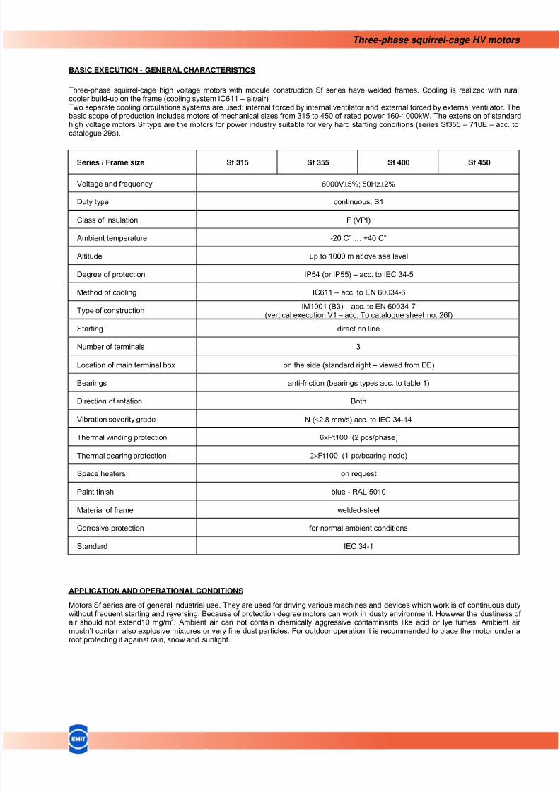
CHANGES IN AMBIENT AND SUPPLY CONDITION
Rated motor load is specified at ambient
temperature +40°C and operational altitudeup to 1000 m above sea level. Whentemperature and / or altitude are changed
motor output should be corrected accordingto the below characteristics..
BALANCING AND ALLOWABLE VIBRATION LEVEL
Motor’s rotor is balanced with half-key installed in free shaft extension.Permissible vibration speed of uncoupled motor is 2,8 mm/s rms.
BEARINGS
Motors Sf series are equipped with rolling bearings with possibility of lubricating during operation and special device to remove usedgrease (taken out „drawer” placed in lower part of external bearing cover).Bearings lubricant - solid grease ŁT-4S3 (Mobillux EP3).
STANDARD
Mechanical Size No. of poles D.E. bearing N.D.E. bearing
2 6317 C3 6317 C3
4 6320 MC3 NU320 EM1Sf 315
6 6320 C3 NU320 EM1
2 6318 C3 6318 C3
Sf 355
4 ÷ 8 NU222 EM1 + 6222 MC3 NU222 EM1
Sf 400 4 ÷ 8 NU226 EM1 + 6226 MC3 NU226 EM1
Sf 450 4 ÷ 12 NU226 EM1 + 6226 MC3 NU226 EM1
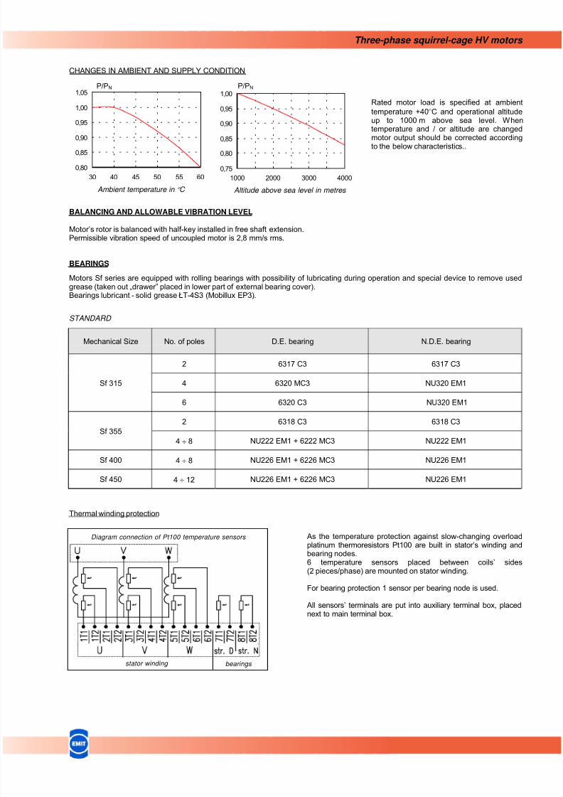
Thermal winding protection
As the temperature protection against slow-changing overloadplatinum thermoresistors Pt100 are built in stator’s winding andbearing nodes.6 temperature sensors placed between coils’ sides(2 pieces/phase) are mounted on stator winding.
For bearing protection 1 sensor per bearing node is used.
All sensors’ terminals are put into auxiliary terminal box, placednext to main terminal box.
0,80
0,85
0,90
0,95
1,00
1,05
30 40 45 50 55 60
P/PN
Ambient temperature in ° C
0,75
0,80
0,85
0,90
0,95
1,00
1000 2000 3000 4000
P/PN
Altitude above sea level in metres
Diagram connection of Pt100 temperature sensors
stator winding bearings
8/4/2019 26b
http://slidepdf.com/reader/full/26b 4/5
Three-phase squirrel-cage HV motors
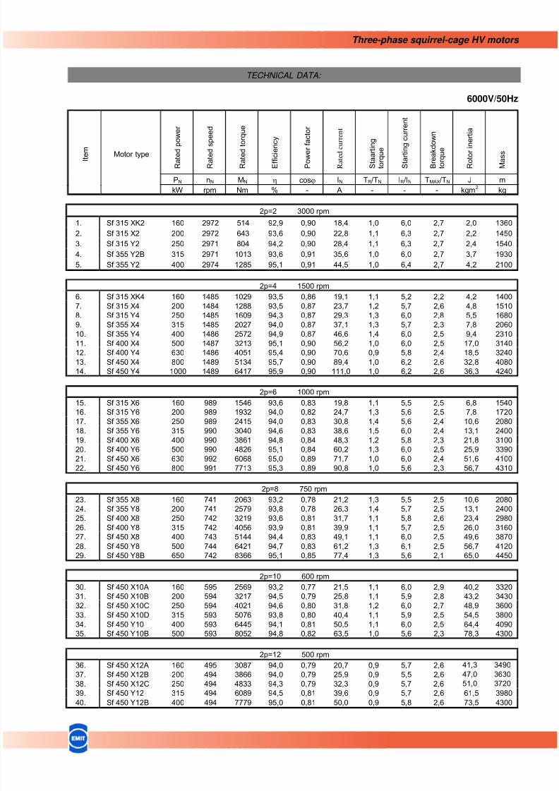
TECHNICAL DATA:
6000V/50Hz
2p=2 3000 rpm
1. Sf 315 XK2 160 2972 514 92,9 0,90 18,4 1,0 6,0 2,7 2,0 1360
2. Sf 315 X2 200 2972 643 93,6 0,90 22,8 1,1 6,3 2,7 2,2 1450
3. Sf 315 Y2 250 2971 804 94,2 0,90 28,4 1,1 6,3 2,7 2,4 1540
4. Sf 355 Y2B 315 2971 1013 93,6 0,91 35,6 1,0 6,0 2,7 3,7 1930
5. Sf 355 Y2 400 2974 1285 95,1 0,91 44,5 1,0 6,4 2,7 4,2 2100
2p=4 1500 rpm
6. Sf 315 XK4 160 1485 1029 93,5 0,86 19,1 1,1 5,2 2,2 4,2 1400
7. Sf 315 X4 200 1484 1288 93,5 0,87 23,7 1,2 5,7 2,6 4,8 1510
8. Sf 315 Y4 250 1485 1609 94,3 0,87 29,3 1,3 6,0 2,8 5,5 1680
9. Sf 355 X4 315 1485 2027 94,0 0,87 37,1 1,3 5,7 2,3 7,8 2060
10. Sf 355 Y4 400 1486 2572 94,9 0,87 46,6 1,4 6,0 2,5 9,4 2310
11. Sf 400 X4 500 1487 3213 95,1 0,90 56,2 1,0 6,0 2,5 17,0 3140
12. Sf 400 Y4 630 1486 4051 95,4 0,90 70,6 0,9 5,8 2,4 18,5 3240
13. Sf 450 X4 800 1489 5134 95,7 0,90 89,4 1,0 6,2 2,6 32,8 4080
14. Sf 450 Y4 1000 1489 6417 95,9 0,90 111,0 1,0 6,2 2,6 36,3 4240
2p=6 1000 rpm
15. Sf 315 X6 160 989 1546 93,6 0,83 19,8 1,1 5,5 2,5 6,8 1540
16. Sf 315 Y6 200 989 1932 94,0 0,82 24,7 1,3 5,6 2,5 7,8 172017. Sf 355 X6 250 989 2415 94,0 0,83 30,8 1,4 5,6 2,4 10,6 2080
18. Sf 355 Y6 315 990 3040 94,6 0,83 38,6 1,5 6,0 2,4 13,1 2400
19. Sf 400 X6 400 990 3861 94,8 0,84 48,3 1,2 5,8 2,3 21,8 3100
20. Sf 400 Y6 500 990 4826 95,1 0,84 60,2 1,3 6,0 2,5 25,9 3390
21. Sf 450 X6 630 992 6068 95,0 0,89 71,7 1,0 6,0 2,4 51,6 4100
22. Sf 450 Y6 800 991 7713 95,3 0,89 90,8 1,0 5,6 2,3 56,7 4310
2p=8 750 rpm
23. Sf 355 X8 160 741 2063 93,2 0,78 21,2 1,3 5,5 2,5 10,6 2080
24. Sf 355 Y8 200 741 2579 93,8 0,78 26,3 1,4 5,7 2,5 13,1 2400
25. Sf 400 X8 250 742 3219 93,6 0,81 31,7 1,1 5,8 2,6 23,4 2980
26. Sf 400 Y8 315 742 4056 93,9 0,81 39,9 1,1 5,7 2,5 26,0 3160
27. Sf 450 X8 400 743 5144 94,4 0,83 49,1 1,1 6,0 2,5 49,6 3870
28. Sf 450 Y8 500 744 6421 94,7 0,83 61,2 1,3 6,1 2,5 56,7 4120
29. Sf 450 Y8B 650 742 8366 95,1 0,85 77,4 1,3 5,6 2,1 65,0 4450
2p=10 600 rpm
30. Sf 450 X10A 160 595 2569 93,2 0,77 21,5 1,1 6,0 2,9 40,2 3320
31. Sf 450 X10B 200 594 3217 94,5 0,79 25,8 1,1 5,9 2,8 43,2 3430
32. Sf 450 X10C 250 594 4021 94,6 0,80 31,8 1,2 6,0 2,7 48,9 3600
33. Sf 450 X10D 315 593 5076 93,8 0,80 40,4 1,1 5,9 2,5 54,5 3800
34. Sf 450 Y10 400 593 6445 94,1 0,81 50,5 1,1 6,0 2,5 64,4 4090
35. Sf 450 Y10B 500 593 8052 94,8 0,82 63,5 1,0 5,6 2,3 78,3 4300
2p=12 500 rpm
36. Sf 450 X12A 160 495 3087 94,0 0,79 20,7 0,9 5,7 2,6 41,3 3490
37. Sf 450 X12B 200 494 3866 94,0 0,79 25,9 0,9 5,5 2,6 47,0 3630
38. Sf 450 X12C 250 494 4833 94,3 0,79 32,3 0,9 5,7 2,6 51,0 3720
39. Sf 450 Y12 315 494 6089 94,5 0,81 39,6 0,9 5,7 2,6 61,5 398040. Sf 450 Y12B 400 494 7779 95,0 0,81 50,0 0,9 5,8 2,6 73,5 4300
R a t e d p o w e r
R a t e d s p e
e d
R a t e d t o r q u e
E f f i c i e n c y
P o w e r f a c
t o r
R a t e d c u r r e n t
S t a a r t i n g
t o r q u e
S t a r t i n g c
u r r e n t
B r e a k d o w
n
t o r q u e
R o t o r i n e r t i a
M a s s
PN nN MN η cosϕ IN TR/TN IR/IN TMAX/TN J m
I t e m
Motor type
kW rpm Nm % - A - - - kgm2
kg
8/4/2019 26b
http://slidepdf.com/reader/full/26b 5/5
Three-phase squirrel-cage HV motors
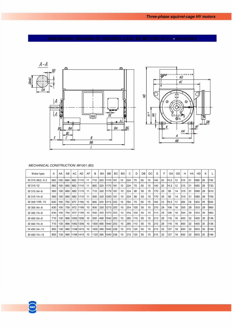
DIMENSIONAL DRAWING OF SQUIRREL-CAGE MV MOTORS SF 315 ÷450 SERIES
MECHANICAL CONSTRUCTION: IM1001 (B3)
Motor type A AA AB AC AD AF B BA BB BC BG C D DB DC E F GA GD H HA HD K L
Sf 315 XK2; X-2 560 100 660 882 1110 11 710 320 1170 181 10 224 70 55 15 140 20 74,5 12 315 31 1085 28 1730
Sf 315 Y2 560 100 660 882 1110 11 800 320 1170 181 10 224 70 55 15 140 20 74,5 12 315 31 1085 28 1730
Sf 315 X4÷6 560 100 660 882 1110 11 710 320 1170 181 10 224 90 55 15 170 25 95 14 315 31 1085 28 1610
Sf 315 Y4÷6 560 100 660 882 1110 11 800 320 1250 181 10 224 90 55 15 170 25 95 14 315 31 1085 28 1700
Sf 355 Y2B; Y2 630 100 750 972 1195 10 900 320 1273 203 10 254 75 55 15 140 20 79,5 12 355 28 1303 28 1930
Sf 355 X4÷8 630 100 750 972 1195 10 800 320 1273 203 10 254 100 55 15 210 28 106 16 355 28 1303 28 1860
Sf 355 Y4÷8 630 100 750 972 1195 10 900 320 1373 203 10 254 100 55 15 210 28 106 16 355 28 1303 28 1960
Sf 400 X4÷8 710 130 866 1092 1306 10 900 490 1540 203 10 280 110 55 15 210 28 116 16 400 32 1400 35 2136
Sf 400 Y4÷8 710 130 866 1092 1306 10 1000 490 1540 203 10 280 110 55 15 210 28 116 16 400 32 1400 35 2136
Sf 450 X4÷12 800 130 980 1198 1415 10 1000 390 1540 238 10 315 120 55 15 210 32 127 18 450 32 1603 35 2146Sf 450 Y4÷12 800 130 980 1198 1415 10 1120 390 1540 238 10 315 120 55 15 210 32 127 18 450 32 1603 35 2146