Embed Size (px)
Citation preview
Fair-Rite Products Corp. PO Box J,One Commercial Row, Wallkill, NY 12589-0288Phone: (888) 324-7748 www.fair-rite.com
Fair-Rite Product's CatalogPart Data Sheet, 2661000801Printed: 2010-11-09
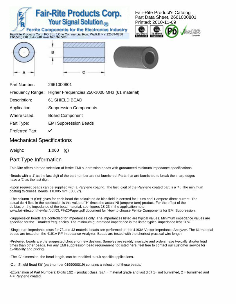
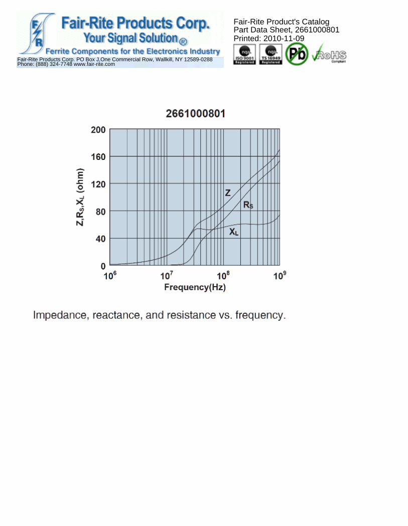
Part Number: 2661000801
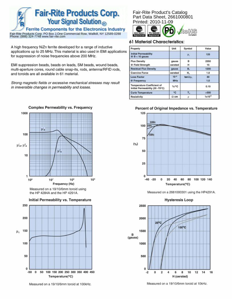
Frequency Range: Higher Frequencies 250-1000 MHz (61 material)
Description: 61 SHIELD BEAD
Application: Suppression Components
Where Used: Board Component
Part Type: EMI Suppression Beads
Preferred Part:
Mechanical Specifications
Weight: 1.000 (g)
Part Type InformationFair-Rite offers a broad selection of ferrite EMI suppression beads with guaranteed minimum impedance specifications.
-Beads with a '1' as the last digit of the part number are not burnished. Parts that are burnished to break the sharp edgeshave a '2' as the last digit.
-Upon request beads can be supplied with a Parylene coating. The last digit of the Parylene coated part is a '4'. The minimumcoating thickness beads is 0.005 mm (.0002'').
-The column 'H (Oe)' gives for each bead the calculated dc bias field in oersted for 1 turn and 1 ampere direct current. Theactual dc H field in the application is this value of 'H' times the actual NI (ampere-turn) product. For the effect of thedc bias on the impedance of the bead material, see figures 18-23 in the application notewww.fair-rite.com/newfair/pdf/CUP%20Paper.pdf document for 'How to choose Ferrite Components for EMI Suppression.
-Suppression beads are controlled for impedances only. The impedances listed are typical values. Minimum impedance values arespecified for the + marked frequencies. The minimum guaranteed impedance is the listed typical impedance less 20%.
-Single turn impedance tests for 73 and 43 material beads are performed on the 4193A Vector Impedance Analyzer. The 61 materialbeads are tested on the 4191A RF Impedance Analyzer. Beads are tested with the shortest practical wire length.
-Preferred beads are the suggested choice for new designs. Samples are readily available and orders have typically shorter leadtimes than other beads. For any EMI suppression bead requirement not listed here, feel free to contact our customer service foravailability and pricing.
-The 'C' dimension, the bead length, can be modified to suit specific applications.
-Our 'Shield Bead Kit' (part number 0199000019) contains a selection of these beads.
-Explanation of Part Numbers: Digits 1&2 = product class, 3&4 = material grade and last digit 1= not burnished, 2 = burnished and4 = Parylene coated.
Fair-Rite Products Corp. PO Box J,One Commercial Row, Wallkill, NY 12589-0288Phone: (888) 324-7748 www.fair-rite.com
Fair-Rite Product's CatalogPart Data Sheet, 2661000801Printed: 2010-11-09
Mechanical Specifications
Dim mm mm nominal inch
tol inch misc.
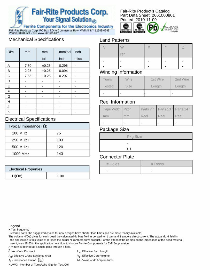
A 7.50 ±0.25 0.296 -
B 2.25 +0.25 0.094 -
C 7.55 ±0.25 0.297 -
D - - - -
E - - - -
F - - - -
G - - - -
H - - - -
J - - - -
K - - - -
Land PatternsV W X Y Z
ref
- - - - -- - - - -
Winding InformationTurns Wire 1st Wire 2nd Wire
Tested Size Length Length
- - - -
Reel InformationTape Width Pitch Parts 7 '' Parts 13 '' Parts 14 ''
mm mm Reel Reel Reel
- - - - -
Package SizePkg Size
-(-)
Electrical SpecificationsTypical Impedance ( )
100 MHz 75
250 MHz+ 103
500 MHz+ 120
1000 MHz 143Connector Plate
# Holes # Rows
- -Electrical Properties
H(Oe) 1.00
Legend + Test frequency Preferred parts, the suggested choice for new designs,have shorter lead times and are more readily available. The column H(Oe) gives for each bead the calculated dc bias field in oersted for 1 turn and 1 ampere direct current. The actual dc H field in
the application is this value of H times the actual NI (ampere-turn) product. For the effect of the dc bias on the impedance of the bead material, see figures 18-23 in the application note How to choose Ferrite Components for EMI Suppression.
A ½ turn is defined as a single pass through a hole.
l/A - Core Constant l e: Effective Path Length
Ae: Effective Cross-Sectional Area Ve: Effective Core Volume
AL- Inductance Factor ( L__N2) Nl - Value of dc Ampere-turns
N/AWG - Number of Turns/Wire Size for Test Coil
Fair-Rite Products Corp. PO Box J,One Commercial Row, Wallkill, NY 12589-0288Phone: (888) 324-7748 www.fair-rite.com
Fair-Rite Product's CatalogPart Data Sheet, 2661000801Printed: 2010-11-09
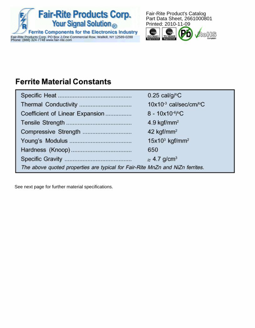
See next page for further material specifications.
Fair-Rite Products Corp. PO Box J,One Commercial Row, Wallkill, NY 12589-0288Phone: (888) 324-7748 www.fair-rite.com
Fair-Rite Product's CatalogPart Data Sheet, 2661000801Printed: 2010-11-09
Fair-Rite Products Corp. PO Box J,One Commercial Row, Wallkill, NY 12589-0288Phone: (888) 324-7748 www.fair-rite.com
Fair-Rite Product's CatalogPart Data Sheet, 2661000801Printed: 2010-11-09


